

Page 1
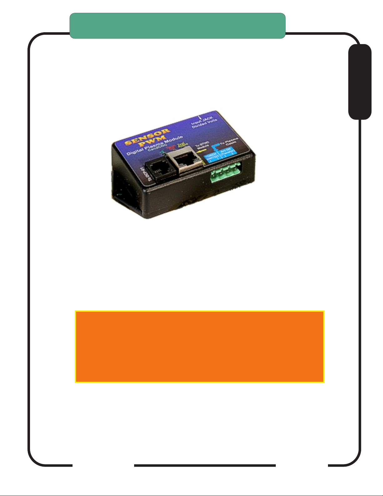
THC SENSOR PWM MODULE
SETTING UP THE THC SENSOR PWM MODULE
IF you already have a working PWM Module with your DTHCIV
of either REV number and you are just upgrading to the DTHC IV
for CommandCNC you can skip this section of the setup
.
PWM MODULE
REV 21 and later
E
This update is to cover the newer PWM rev 21, PWM Mod2 and the
soon to be released PWM II
UPDATED for PWM, newerPWM MOD2
and PWM II
10/22/17
CandCNC
Page 1
Page 2
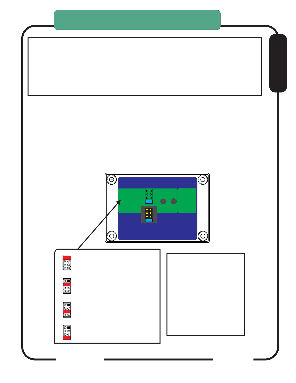
SETTING THE THC SENSOR PWM PRESCALE
DIVIDER RATIO( REV21)
THIS MUST BE DONE TO MATCH YOUR INSTALL
UNITS ARE SHIPPED TO MATCH THE RAV-01 (7:1)
RATIO. USE THE CHART BELOW IF YOU ARE USING
THE MODULE WITH A PLASMA WITH AN INTERNAL
VOLTAGE DIVIDER. SEE THE SECTION ON
CONNECTING A PLASMA WITH AN INTERNAL
VOLTAGE DIVIDER TO DETERMINE TE PROPER RATIO
To set PWM SENSOR ratio divider option:
1. Turn case over. There is a small access slot for the
Prescale Jumpers
2. Determine the proper setting for the type setup you have.
3. Set the small option jumper to match.
Prior MODEL
PWM
Shown
THC Sensor PWM REV21
For use with
Hypertherm
TD & Others
RAV-01/02
(Factory Default)
50:1
20:1
Not Used XX
Check jumper settings
to match plasma divider ratio
Remove back to access jumper
7:1
DTHC II
VOLTS
Press and release
Volts Test. Front panel
will light
settings
TEST
DTHC IV
ARC
OK
LED Test Active
Rear
Press and
Hold for
ARC OK
TEST
E
Volts
Volts
SCALE
SCALE
50:1 Scale (Hypertherm and
50:1
20:1
some others) Recommended
for Hypertherm with CPC
7:1
Volts
Volts
SCALE
SCALE
50:1
50:1
20:1 Standard on some
20:1
20:1
Thermal Dynamics, others
7:1
7:1
Volts
Volts
SCALE
SCALE
50:1
30:1 Divider
20:1
30:1
(Not ON Sensor PWM)
7:1
Volts
Volts
SCALE
SCALE
7:1 Divider
50:1
20:1
(from CandCNC RAV-01
N/A
7:1
Card )
DEFAULT
CandCNC
IMPORTANT:
The Hypertherm 45 has an
internal voltage divider. It
cannot be changed from the
50:1 ratio. Set your PWM
Sensor jumper to the 50:1
position if you are using the
MIC-01 Direct Connect
Cable.
Page 2
Page 3
CandCNC
Page 3
Page 4
THC SENSOR PWM MODULE VOLTS
TEST/CAL
THC SENSOR PWM MODULE TEST/CAL
Front
SENSORSENSOR
PWM PWM
Digital Plasma Module
MOD 2
To DCP-01
To DCP-01
CandCNC
Torch
+5
ON
+12 PWR
Test
Active
Arc OK
Input JACK
Input JACK
Divided Volts
Divided Volts
To DTHC
Module
To DTHC
Module
Digital Plasma
TORCH
SWITCH
ARC OK
ARC OK
To Plasma
Arc OK
Module
(Transfer)
CandCNC
To Plasma
To CPC or RAV-02
Cable
THC Sensor PWM REV21
For use with
Hypertherm
TD & Others
RAV-01/02
(Factory Default)
50:1
20:1
Not Used XX
7:1
Check jumper settings
to match plasma divider ratio
DTHC II
DTHC IV
TEST
VOLTS
Press and release
Volts Test. Front panel
will light
ARC
OK
LED Test Active
Press and
Hold for
ARC OK
TEST
E
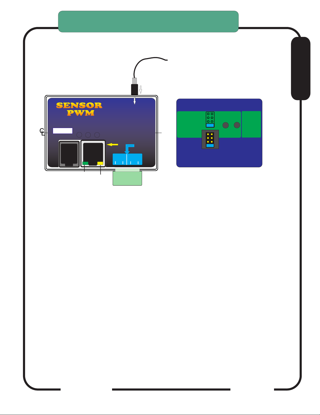
THC PWM Module (Plasma Pickup Module) can be put in TEST/CAL mode
without removing the card from the case.
Turn the case over and look on the back. There are two recessed test buttons
find the button marked VOLTS.
Unplug the Divided Volts (from the plasma) either the 2 pin plug or the stereo
plug. Leaving the Divided Volts plugged in will Skew the reading.
Push and release Volts Test, this puts the unit in test/cal mode. The yellow
Test Active on the front will flash. You should see 126 to 128 volts displayed on
the TORCH VOLTS in the CommandCNC screen
Pushing the button again will take the unit out of test/cal mode and the LED will
stop flashing and the TORCH VOLTS reading will return to Zero.
In TEST mode the PWM signal to the DTHCIV is tested. If you unit passes the
Volts Test then the Cat5 cable and DTHCIV module are operating properly. If
the voltage is still wrong or zero when the torch fires then the cable to plasma is
bad or the voltage divider in the plasma is bad.
The test is based on a simulated PWM from the circuit so if the prescale divider
setting is wrong the calibration will show correct but when the torch is fired
the voltage will be wrong.
CandCNC
Page 4
Page 5
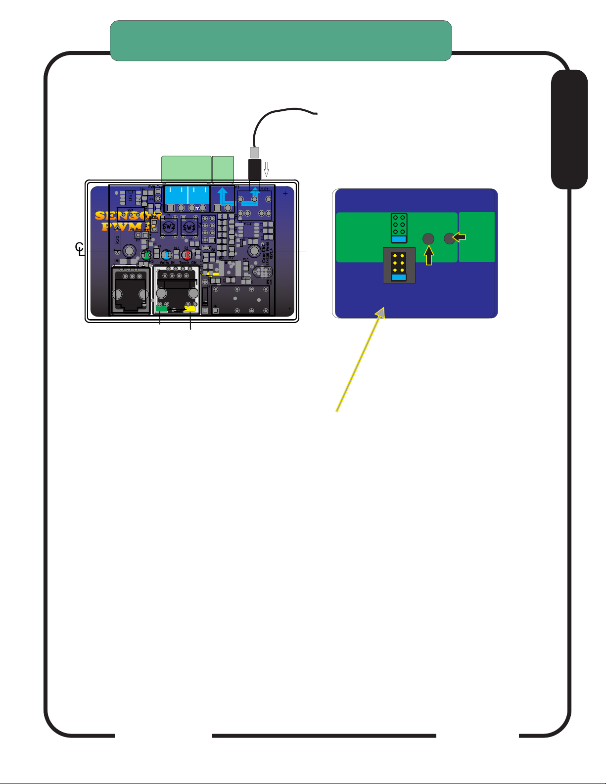
THC SENSOR PWM MODULE VOLTS
TEST/CAL
Test
Active
THC SENSOR PWM II MODULE TEST/CAL
Front
SENSORSENSOR
PWM PWM
To DCP-01
To CPC or RAV-02
Arc OK
(Transfer)
To Plasma
Cable
IIII
Volts IN
+5
ACT
+12 PWR
TORCH
SWITCH
Torch
ON
Arc OK
Input JACK
Divided Volts
To DTHC
Module
Digital Plasma
Module
CandCNC
ARC OK
THC Sensor PWM REV21
For use with
Hypertherm
TD & Others
RAV-01/02
(Factory Default)
50:1
20:1
TD/Victor 30:1
7:1
Check jumper settings
to match plasma divider ratio
DTHC IV
DTHC V
TEST
VOLTS
Press and HOLD
Volts Test. Front panel
will flash
ARC
OK
blue LED Volts ACTive
Press and
Hold for
ARC OK
TEST
E
THC PWM II Module Rev 1.4 (Plasma Pickup Module) can be put in TEST/CAL
mode without removing the card from the case.
Turn the case over and look on the back. There are two recessed test buttons
find the button marked VOLTS.
Unplug the Divided Volts (from the plasma) either the 2 pin plug or the stereo
plug. Leaving the Divided Volts plugged in will Skew the reading.
Push and hold Volts Test puts the unit in test/cal mode. The blue Volts IN ACT
LED on the front will flash. You should see 126 to 128 volts displayed on the
TORCH VOLTS in the CommandCNC screen
Releasing the button will take the unit out of test/cal mode and the LED will stop
flashing and the TORCH VOLTS reading will return to Zero.
In TEST mode the PWM is completely tested. If you unit passes the Volts Test
but the voltage is still wrong or zero when the torch fires then the cable to
plasma is bad or the voltage divider in the plasma is bad.
The test is based on a simulated PWM from the circuit so if the prescale divider
setting is wrong the calibration will show correct but when the torch is fired
the voltage will be wrong.
CandCNC
Page 5
Page 6
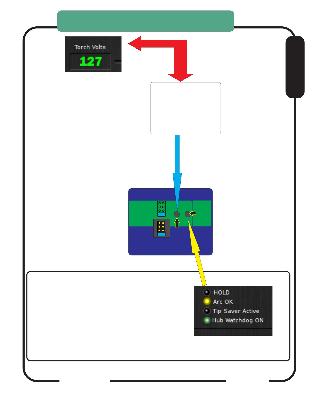
THC SENSOR PWM MODULE VOLTS
TEST/CAL
Depress and Hold TEST button
to test PWM circuit back to
DTHCIV. Volts ACT LED on
front will flash and DTHC
screen in CommanCNC should
display a voltage. Calibrated
units (see DTHC calibration
section) should display 126 to
128 volts during test.
CandCNC THC SENSOR
PWM and PWMII
E
SENSOR
PWM
THC Sensor PWM REV21
For use with
Hypertherm
TD & Others
TD/Victor 30:1
RAV-01/02
(Factory Default)
Check jumper settings
to match plasma divider ratio
50:1
20:1
7:1
DTHC IV
VOLTS
Press and HOLD
Volts Test. Front panel
will flash
CHECKING ARC OK SIGNAL BACK TO DTHCIV
CARD:
1. Turn case over.
2 With RJ45 (UTP cable) connected to DTHCIV and
unit powered up, depress the ARC OK TEST
BUTTON on the card. The ARC OK LED on the
MACH screen should light. The ARC OK test LED
on the front of the case will light.
Case not shown for clearity
DTHC V
TEST
ARC
OK
blue LED Volts ACTive
Press and
Hold for
ARC OK
TEST
CandCNC
Screen may be different
Page 6
Page 7

THC SENSOR PWM MODULE VOLTS
TEST/CAL
Before you make connections to the plasma unit you may want to do some testing
to confirm proper operation of the THC SENSOR PWM with the DTHC II/ IV Module.
Connect the THC SENSOR PWM (or Sensor PWM II MODULE ) to the RJ45
(CAT5) connector on the DTHCIV Module. Be careful! Do not connect the CAT5
from the DTHCIV module to ANY OTHER RJ45 jack. It has voltages that can
damage other modules (like the USB to RS485 4 port hub or the Ethernet jack on
the controller or your PC
Start CommandCNC using the Desktop Icon Plasma Profile and make sure you
can come out of RESET and that the CP (Charge Pump) LED on the front of the
MP3600/ BladeRunner is ON.
On full controller products you have to have the Motor DC on to come out of
RESET.
Click on the TORCH icon on the screen. You should see the LED above the
TORCH button on CommandCNC turn on and there will be a click in the THC Sensor
PWM card and the small LED on the front labeled TORCH ON will light. That indicates
the TORCH ON relay is working.
E
The next check is to confirm the ARC OK circuit is working. Follow the instructions
for the THC SENSOR PWM section and open the back and use the ARC OK Test
button. The ARC OK LED on the MACH3 Screen should light. If it does you can
proceed to the actual hookup of the THC SENSOR PWM Module to your plasma unit.
If any of the tests fail make sure you have the cables firmly attached and that
they are the correct type.
All cards are tested at least twice and most three times before they leave the factory. It’s
unusual for a THC SENSOR PWM to be bad or fail in no load testing. If you have
checked all of the connections, cables and MACH setup and you still cannot get the THC
SENSOR to work contact us at 903-364-2740 or via e-mail at [email protected]
NOTE: Some Larger (>100A) plasma units or older smaller models use various methods
to start the initial ARC. Most common is HF (High Frequency) start. HF Start presents
several challenges. It uses the concept that higher frequency waves travel through air
(and arc) easier than DC voltage. The HF is normally combined with a higher voltage and
it starts an ARC that the plasma uses to ignite the air. Once the arc fires, if a conductive
part is close, the arc will transfer to the material. The HF start causes a lot of noise and
current spikes. The other form of High Voltage start is the CD (Capacitor Discharge)
method. It is basically a high current version of an Automotive ignition system. Up to
30,000 volts can be generated. If the THC Sensor is not protected, the high voltage and
high frequency can cause component failure on the card or (worse) in the THC unit and
even burn the board. The THC Sensor PWM (REV18 and up) is protected from HF and
most High Voltage start circuits.
CandCNC
Page 7
Page 8
MAKING CONNECTIONS TO
YOUR PLASMA CUTTER
1. You need the proper CandCNC Plasma Connection Kit to make the interface to
your plasma cutter.
2. Different types of plasma cutters can be used. Some have everything needed
terminated to one connector (e.g. Hypertherm 45/65/85/105/125) with rear CPC.
Others may have the same or no external connectors. We can only cover a few
specific types.
NOTE: Some plasma cutters use a manual contact start (TAP start) when the end
of the torch has to touch the metal then be retracted to start the arc. These types
of cutters WILL NOT WORK for plasma CNC cutting.
A note about HF start plasma cutters and the DTHCIV.
The DTHCIV is highly isolated from the plasma side and the noise from an HF
start plasma will not enter the controlls thought the PWM module or the
DTHCIV. Most problems from HF start are from having a common
connection to the control side (motor power supply, PC or monitor, etc)
The table and plasma chassis needs a good local earth ground (rod) close to
the table. You need to separate the Plasma cutter and its cables as far as
possible from the controls. You should NOT tie the control side to the same
ground rod as the plasma or table is connected to. The AC safety grounds
between the two systems need to connect at one common point (only) and as
physically separated as possible. In severe cases you may need to provide a
separate clean ground to the control side or even place the control equipment in
a shielded metal enclosure NOT connected to the plasma ground. Even earth
grounded wires with high currents running through them will induct some noise
into anything tied to the same ground. Just a few volts of noise on a shared
ground can disrupt the operation of some PC’s. If you fire your torch and the
PC locks up , CommandCNC stops responding, or the controller does weird
things, you need to start separating the source of the noise (the plasma cutter
and the torch leads) away from the PC control side and break any LOCAL
common connections...even grounds.
E
CandCNC
Page 8
Page 9
MAKING CONNECTIONS TO
YOUR PLASMA CUTTER
The smaller Hypertherm and other modern brand units use a low noise method called
“blowback arc start”. The electrode is mounted against a spring that keeps it pushed
against the inside of the nozzle as long as air is not flowing. When the unit is triggered the
ARC starts a few milliseconds after the current starts to flow in the electrode circuit. As the
air flows it pulls the electrode away from the nozzle and creates an ARC. That is used to
ionize the air and start the plasma.
The DTHC IV can be used with all types of plasma units. The HF units tend to be very
noisy and some even have large amounts of RFI. The total isolation of the DTHC IV circuit
from any low level (PC logic) including any common ground, stops any conducted noise.
The internal circuits are protected from RFI with proper layout and careful attention to
bypass components on all active circuits.
Hooking Up Your Plasma Machine to the MP3600-DTHC IV/BladeRunnerAIO
DTHC IV LINUX
NOTE: IF you have a Hypertherm with a rear “CPC (14 pin) round connector
you can skip this section.
E
CAUTION: Portions of this install may include opening your plasma cutter machine and attaching wires.
MAKE SURE THE UNIT IS UNPLUGGED PRIOR TO REMOVING ANY COVER(S) OR MAKING ANY
CONNECTIONS. Plasma units have HIGH VOLTAGES present that can be dangerous or lethal. IF
YOU ARE NOT EXPERIENCED WORKING WITH HIGH VOLTAGES, DO NOT ATTEMPT TO INSTALL
THIS OR ANY OTHER DEVICE INSIDE YOUR PLASMA UNIT YOURSELF. SEEK PROFESSIONAL
HELP.
In order to control your plasma unit, there are three main connections that need to be made to the
plasma unit itself. All of the following operations are to be done with the power disconnected from your
plasma unit.
You should determine which type install you will need for your plasma.
There are 3 questions that need to be answered:
1.) Does your plasma unit have an internal ARC OK (dry contact) signal or one on a standard CPC
connector? If not then you will need to purchase and install the Digital Current Probe Option (DCP-01).
it is available separately or as part of the Universal Connection Kit
2.) Does your plasma unit have an internal voltage divider (Automation Interface) with a ratio of 20:1 or
50:1 ? If not you will need to purchase and install the Raw Arc Volts divider card (RAV-01). It is
available separately or as part of the Universal Connection Kit
3.) Are you using a hand torch or machine torch? If using a hand torch (even with a unit that is setup for
automation, you will probably need to tap into the TORCH SWITCH wires from the hand torch to fire
the torch remotely (from the computer). There is a page on how to do that from either the RAV-01 (if
you already have it because of #2 above) or directly from the THC SENSOR PWM connector.
If you have a Plasma unit that needs the RAV-02 card you will need to install that card in your plasma
unit or have it done. See the RAV-02 card section for instructions and warnings. If you are using the
DCP-01 for ARC OK, there is an addendum at the end of this manual on installing and testing the DCP-
01.
DTHCIV1-14_2
CandCNC
Page 9
Page 10

SELECT PLASMA CONNECTION KIT
NOTE: IF you have a Hypertherm or Thermal Dynamcis “A”
series with a rear “CPC (14 pin) round connector you can skip
this section.
1. Most plasma units have connection terminals where wires from the torch or panel connectors
attach to the internal PC Boards. The terminals provide a convenient place to do your connections.
Use crimp-on spade or round terminals to attach the wires to the terminal strips. Make sure the new
wires you install do not touch adjacent metal objects. On some machines there may be more than
one set of small wires and are used for sensing tip shorts and other conditions. To identity the
correct pair for the Torch Switch use an ohmmeter or continuity checker across each pair while
you manually push the torch head button. When you identify the pair make note of where they
attach. Use #22 to #18 stranded wire (twisted pair) to connect between the two screw terminals on
the THC Sensor PCB marked “Torch Switch” to the two switch terminals in the plasma unit.
There is no polarity. NOTE: IF your unit has noise filter chokes from the
torch switch wires up to its internal logic card, it is recommended you place
the two wires to the RAV-02 PCB on the other side of the chokes from
their torch head connection (end closest to the internal logic card).
2. If your unit has a Raw Arc Voltage connection point (i.e. like the Hypertherm
1000 series), you will need to use their manual and suggestions as to how
to connect to the two points and run those wires to the RAV-02 card.
Just make sure you use wire that has insulation rated for at least 400 V.
Small signal wire like telephone wire (UTP) is not rated that high and can
arc to nearby components. The RAV-02 card is designed to take the
full tip voltage and divide and filter it. Open circuit full tip voltage can be
as high as 300VDC in some machines.
E
3. If your plasma unit does not have a designated tip voltage measurement point, you will
need to locate a place inside the unit where
you can get one wire onto the WORK CLAMP lead and another on the heavy
lead(s) that connects to the torch tip (ELECTRODE).
a. Note: some machines like the Hypertherm 380 do not have a single
heavy wire to the Torch tip and instead have a set of parallel smaller
wires that all terminate into one connector. In the case of the 380 the
WHITE wires are the tip volts negative.
b. You can identify both locations by visually tracing the two leads as
they come into the box. You should find several locations/terminal strips that have connections to
these two points and you can use those for your sense wire connections. Use unshielded stranded.
c. Make a connection between the locations you have identified that tie directly to the two
leads (workclamp and torch tip) to the two “TIP Volts” terminals. Make sure that these wires are
routed where they cannot come into contact with hot or moving components. The TIP VOLTS inputs
on the RAV-02 card have a polarity. The + side is the Workclamp and the - side is the Electrode
CandCNC
Page 10
Page 11

MAKING CONNECTIONS TO
YOUR PLASMA CUTTER
5. If you are using the CandCNC Digital Current Probe (DCP) with a
plasma that does not have an ARC OK signal , the DCP01 provides a
current feedback to CommandCNC and the ARC OK trip point is set and
provides a software based ARC OK
6. If you have a plasma unit that DOES have an Arc Good signal and
you have the DCP module, either signal will trip the ARC OK.
Note: The term Arc Good is interchangeable with Arc Ok , Arc Xfer and OK
to MOVE.
7. NOTE: IT IS ESSENTIAL that the chassis of the plasma table have a
good earth ground. Refer to the suggested grounding section of the
diagrams and provide for a good earth ground close to the table. A
safety ground back to a breaker panel many feet away may be a good
ground for AC frequencies (60hz) but poor for higher frequencies like
plasma noise.
E
CandCNC
Page 11
Page 12

USING RAW ARC VOLTAGE CARD
DISCLAIMER AND LEGAL NOTICE
The following section covers the installation of a Voltage Divider card inside the plasma unit.
There are dangerous and possibly lethal voltages present in a plasma power supply/unit.
ALWAYS UNPLUG THE UNIT FROM THE AC POWER BEFORE REMOVING ANY COVERS.
ALWAYS REPLACE ALL COVERS AND SAFETY BARRIERS BEFORE TURNING THE
POWER BACK ON.
You do any install of a card inside of your Plasma Power Unit AT YOUR OWN RISK. If you
do not wish to do the procedure either find a person qualified to do so OR contact us for
options.
CandCNC/Fourhills Designs (hereafter referred to as “CandCNC”) nor any of its
resellers or agents will be responsible for any damage to any plasma unit or the loss of
any income resulting from using any of our electronics or using our instructions written or
verbal to connect to any electronics. While we take care to provide accurate and concise
information, we will not be responsible for any damages to equipment, personnel, or
surrounding equipment, structures or land resulting from the direct or indirect use of our
products.
E
The entire liability of CandCNC or any of its agents or employees is to replace or
repair products provided by CandCNC. Under no circumstances will we be liable for any
damages or loss exceeding the value of the actual products provided by us regardless if the
products are used as described and in the proper manner. All CandCNC products carry a
warranty that covers repair or replacement ONLY. Any labor, travel expense or costs to
replace a component or product outside the CandCNC factory is NOT COVERED by
warranty.
If you do not accept the terms of this notice DO NOT OPEN OR INSTALL THE
RAV-01 CARD. Return the card for a full refund and seek an alternative way to sense
the voltage.
CAUTION: Some plasma units use a very high voltage spark (Capacitor Discharge
or CD) arc starting system. While the RAV-01 card is protected from high voltage inputs
CD type systems can cause arcing in the connecting wires or to nearby components.
If you have a CD start unit and do not have experience working with high voltage systems
SEEK PROFESSIONAL HELP to do any install.
CandCNC
Page 12
Page 13
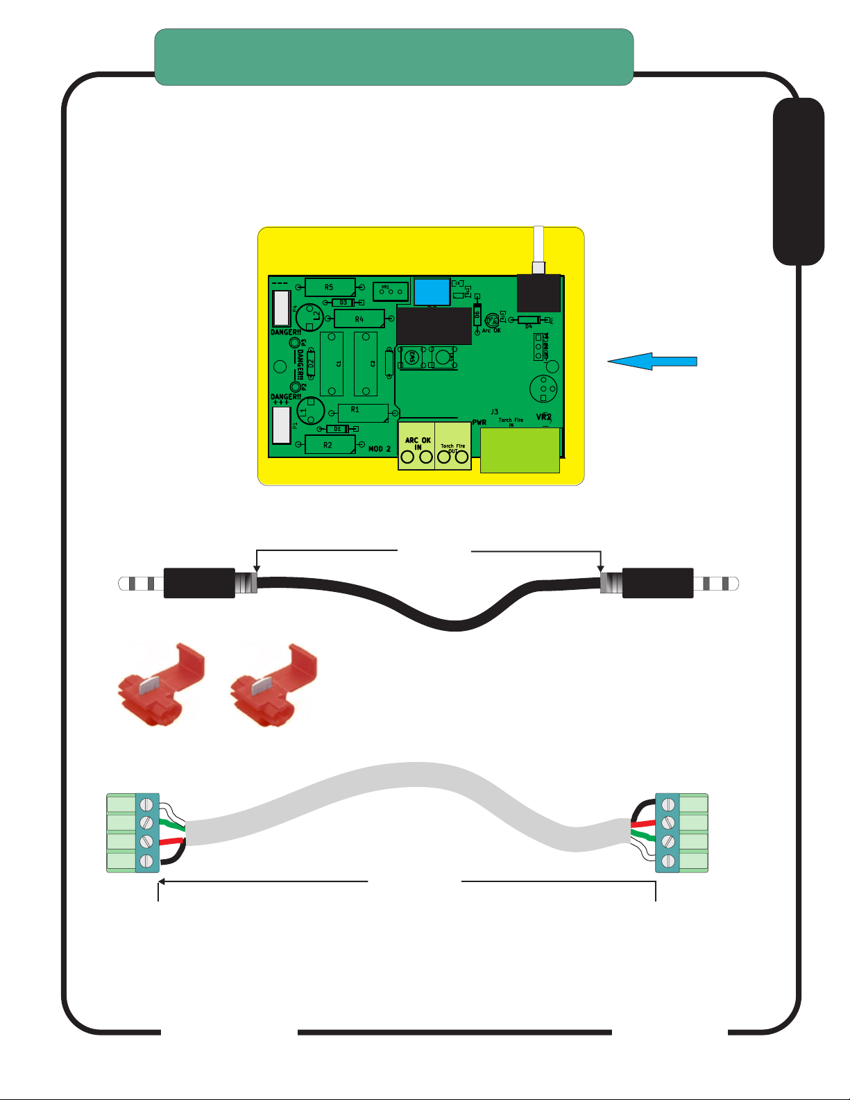
CONNECTING to YOUR PLASMA
RAV-012 Raw Arc Voltage Divider Option
For Plasma Units WITHOUT Internal Voltage Divider
NOTE this card comes in most of the Connections Kits including
the UNIVERSAL CONNECTION KIT
RAV-02 Raw Arc Volts CARD
Module
E
Plexglas
Insulator
Base
(safety shield)
SHIELDED ANALOG CABLE
36” Nom
Part# SAC-01
ScotchLOC™
IDC Splices (RED)
2 pieces
RAV to THCSensorPWM Interconnect
1
PART # CCAB-31
1
36” (min)
CandCNC
Page 13
Page 14
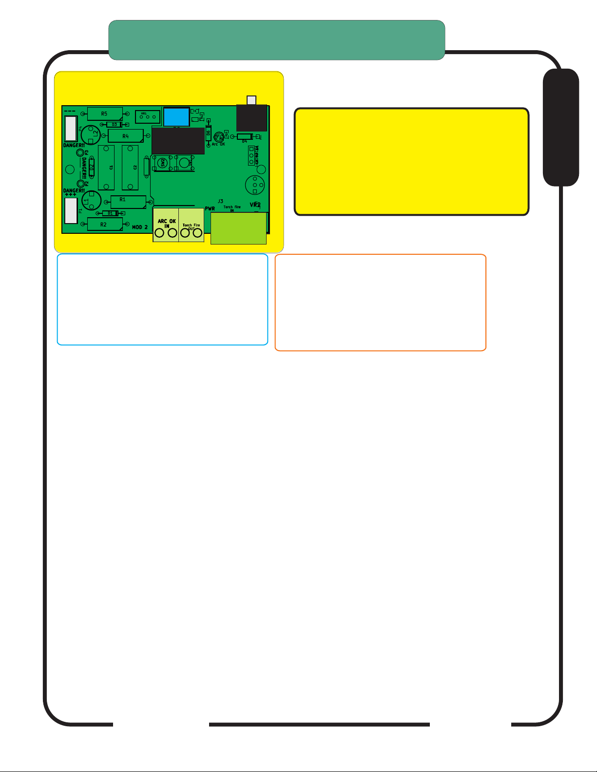
CONNECTING to YOUR PLASMA
RAV-02 Raw Arc Voltage Divider Option
Later version RAV-02
IF YOU HAVE AN INTERNAL ARC OK SIGNAL:
Connect one wire to Terminal 4 and Terminal 3
above (left two terminals)
IF YOU DO NOT HAVE AN INTERNAL ARC OK
SIGNAL: You will need to purchase a DCP-01
Digital Current Probe.
RAV-02 PREFACE: General Information
RAV-02 Raw Arc Volts CARD
IMPORTANT: When making any connection inside
Module
the Plasma Unit, disconnect the unit from the AC
Line (unplug it). Do not open the case with power
on the AC line. THERE ARE DANGEROUS
VOLTAGES present in the unit anytime it is
connected to an AC source EVEN IF IT IS
TURNED OFF.
TORCH SWITCH Terminals.
If you have a plasma unit with a Machine Torch you
will need to locate the two torch fire connection
points. in some units it is called START. IT is a
REMOTE Fire set of wires.
IF YOU HAVE A HAND TORCH you will need to
identify the two Torch Switch wires that come from
the Hand torch and
E
The RAV-02 can be used several ways so it can get confusing about making the connections.
The primary use of the RAV-02 is to take Raw Arc Volts (undivided volts and divide it by a
precise ratio so it can be used by the THC SENSOR PWM module to generate a digital signal
to send volts data to the DTHCII Digital Torch Height Module. In some circumstances that is all
that you will use the card for. Examples are on the Hypertherm 1000/1250/1650 series and the
Older Thermal Dynamics “A” series. Both types have a rear CPC connector (14 pin) that has
the Torch Fire and ARC OK signals available and are used with the CandCNC MIC-02 interface
cable so ONLY the Shielded Analog Cable (SAC-01) is used between the RAV-01 and THC
SENSOR PWM.
On other types of Plasma cutters that have no external connectors for ANY of the required
signals the RAV-01 can become a connection board for accessing those signals internally and
passing them to the THC SENSOR PWM Module via the CCAS-01 4 wire cable. The following
pages will cover how to first use the RAV-02 as a voltage divider card in a unit that does not
have an integrated voltage divider. If you have a plasma unit with no external connectors than
the next section shows how to use the RAV-02 to fire the torch from the software. Finally if
your plasma has an internal access to the Torch fire for a mechanical torch and an internal ARC
OK (OK to MOVE). REMEMBER: the RAV-02 is just a pass-through (place to make
connections) for ARC OK and TORCH FIRE. It does not sense or provide those signals.
There are added pages on some Plasma Cutters and how to connect them; sometimes there is
more than one way. If there is a way to access the proper signals externally than that method
with a cable is recommended. In each case the objective is to get the signals in and out of the
THC SENSOR PWM Module.
CandCNC
Page 14
Page 15
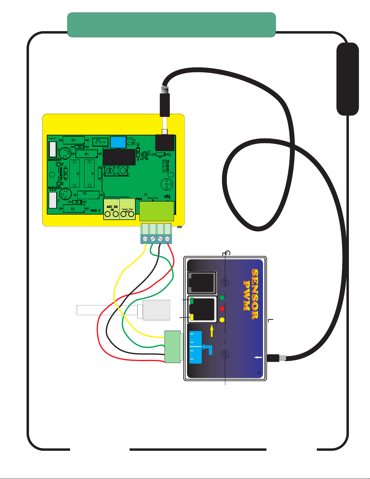
CONNECTING to YOUR PLASMA
RAV-01 Raw Arc Voltage Divider Option
RAV-02 Mounted inside Plasma UNIT.
CandCNC RAW ARC VOLTS Voltage divider card
Later version RAV-02
E
Plexiglas
Safety
Shield
Module
1
RJ45 (Cat5) cable to
DTHCII Module
To CPC or RAV-01
Note: Same wire colors
are used on the PWM II
THC SENSOR PWM MODULE
Mounted outside plasma unit
+12 PWR
Arc OK
To DCP-01
ARC OK
SWITCH
TORCH
(Transfer)
Arc OK
To Plasma
Cable
To DTHC
Module
Digital Plasma Module
SENSORSENSOR
PWM PWM
CandCNC
+5
Torch
ON
Active
Test
Divided Volts
Input JACK
Front
Divided volts from
CandCNC Raw Arc
Volts card
Connections for PWM II MODULE are the SAME
CandCNC
Page 15
Page 16

CONNECTING to YOUR PLASMA
RAV-02 Raw Arc Voltage Divider Option
For Plasma Units that have NO external connector for the required
signals OR do not have an internal voltage divider.
Mounting the RAV-02 Card inside your Plasma Cutter:
Do any mounting or modification with the
Power cord DISCONNECTED to the plasma unit
The mounting location for the card will vary from one type/brand of plasma
unit to another. Pick a location and mount the RAV-01 using the Plexiglass shield
using small self tapping screws (not furnished) or adhesive Velcro strips. Mount
the card at least 1 inch away on all sides from any internal cards, terminals or bare
wires. The standoffs of the card are insulated and so the card can be mounted
with the plexiglass shield against the chassis. There is high voltage present when
the torch fires at the end of the card where the RAW ARC VOLTS (tip Volts) is connected.
Keep that end of the card away from ANY conductive object closer than 2 inches.
Once you have the RAV-01 Card mounted in a safe location you will need
to make provisions to connect the two low voltage cables (CCAB-31 and SAC-01).
You need to provide holes on the rear or side of the unit (BE CAREFUL DRILLING
METAL IN YOUR UNIT. TINY SHAVINGS CAN FALL ON PARTS THAT COULD
SHORT.) Ream the holes smooth or drill them oversized and use a rubber
grommet to protect the wires. Clean up with a magnet or blow the cabinet out
with air. One hole needs to be able to pass the diameter of the SAC-01 Plug. The
other needs to pass the diameter of the cable for the CCAB-31. NOTE: The
4 wide plug on the CCAB-31 cable is removable. You will need to remove the
end that passes into the enclosure to fish the wire through for the RAV-01 Connection.
BE SURE TO FOLLOW THE COLOR CODE TO REATTACH THE CONNECTOR.
THE COLORS ON BOTH ENDS WILL GO ONTO THE SAME TERMINAL/PIN
NUMBER. Connect the two cables where the diagram shows to the RAV-01 Card.
E
Making the connections
A WORD ABOUT ARC OK SIGNALS: “ARC OK” is our terminology of a signal coming back
from the plasma unit that signals the unit has fired the torch and has a valid arc. Most plasma
units made for manual cutting DO NOT HAVE an ARC OK (also known as ARC XFR;
TRANSFER; OK to MOVE and other similar terms). It is a circuit that closes (relay contacts or
sometimes called “dry contacts”) on a valid arc. Units that do have the signal will have it
labeled, on a connector or covered in their manual. IF YOU HAVE DOUBTS, assume the unit
does NOT have ARC OK and follow the guidelines below.
IF YOUR PLASMA HAS AN ARC OK CONNECTION POINT: There will be two connection points.
Run a small gauge (18-24 ga) pair of wires from the internal ARC OK points to the two screw
terminals on the edge of the RAV-01 Card. This wire carries no high voltage or current. Follow the
diagram on Page ____. There is a board labeling program on some cards where the white printing
is WRONG! USE THE PICTURES IN THIS MANUAL to make the connection. Make sure the
connection is secure and that no stray wires are outside the opening of the screw terminals.
IF YOUR PLASMA DOES NOT HAVE AN ARC OK CONNECTION POINT: Turn to the section on
the DCP-01 Digital Current Probe option. You will need to purchase and install this option to
provide a reliable ARC OK signal to your DTHCII system.
CandCNC
Page 16
Page 17

CONNECTING to YOUR PLASMA
RAV-01 Raw Arc Voltage Divider Option
Finding the correct connections.
The first signal you need to identify and locate is the Raw Arc Volts (Raw Tip Volts). This is
the voltage between the Electrode and the Workclamp. The Hypertherm 1000 thru 1650
series have two spade terminals (J15 and J16) that are for easy connection of Raw Arc Volts.
On later models (45/65/85/105/125) WITHOUT the internal voltage divider, the location of the
Raw Arc Volts is not as obvious but they have Field Service Bulletins where they give detailed
directions on finding the Raw Arc Volts. Our manual covers connection to the PowerMax
1000, 1250 and 1650 as well as the PowerMax 45 and PowerMax 65/85/105 with the optional
CPC connector.
https://www.hypertherm.com/Xnet/library.jsp/null is a search page where you can enter your
model number and then search the FSBs. The files are in PDF format.
For other brands of plasma units or a model not designed to be automated the search for
connection points may be a little more difficult but not impossible. The key is the leads going
to the torch cable. On most plasma units you can locate these signals by opening the unit
(POWER DISCONNECTED!) and visually tracing the wires coming from the plasma torch.
The Workclamp will be connected to a stud or terminal inside and is pretty easy to identify. It
is the POSITIVE (+) side of the circuit. The Electrode side goes up the plasma cable to the
torch head. It will be one heavy wire or a series of smaller gauge (12ga or larger) stranded
wires of the same color and they will all connect to the same electrical spot (bus) inside the
plasma. In a lot of units these wires are all solid WHITE in color but do not use color as your
clue. Some plasma manufacturers provide block level schematics in their use or service
manual that give wire colors (and in some cases terminal numbers and locations).
E
WHEN YOU HAVE LOCATED THE WORKCLAMP AND ELECTRODE WIRES IN THE UNIT:
Using a two conductor wire (18-22 ga) [not supplied] with insulation rated to 400V or more
crimp on two ring or fork terminals. USE WIRES OF TWO DIFFERENT COLORS and long
enough to reach the RAV-02 Card using an indirect route (give yourself extra wire). Run the
first color wire (red or the brightest color) to where the WORKCLAMP attaches. Normally that
will be a heavy bus bar with other smaller wires attached. If it is a single large stud you will
need a ring terminal that will fit over the stud. That will be your positive (+) wire.
Use the other wire color and run a connection using a ring or fork terminal to where the
ELECTRODE wires attach.
Carefully route both wires from their connection points over to where they will attach at spade
inputs on the edge of the RAV-01 Card. Keep the wires away from other high voltage wires or
components on the circuit board. Use nylon wire ties to secure the wires to other wire bundles
or to the chassis. DO NOT WIRE TIE THEM TO COMPONENTS ON THE PC BOARDS. DO
NOT USE LOW VOLTAGE WIRES LIKE THOSE USED FOR WIRING PHONES OF
NETWORKS.
DTHCIV1-14_2
CandCNC
Page 17
Page 18

USING THE RAV-01 TO FIRE THE TORCH
(for plasam units with no external connector
to fire the torch or with a hand torch)
The next internal signal you need to locate is the TORCH SWITCH. If you are connecting
to a unit with a Hand Torch you will need to find and tap into the two wires coming from the
torch switch in the hand piece. How will you know? First the wires will be smaller and
different colors than the ELECTRODE or PILOT ARC (more about that later) wires. In most
cases there will be four smaller wires. Two will be the torch switch and two will be the PIP
or CIP (Consummables-In-Place) wires. Once again the manufacturers documents can be
of service here identifying colors and even connection points. If you do not have the
manufacturers service information with schematics and cannot find them on-line you will
need to do a little detective work to identify the torch switch wired.
The first thing your should do is get an Ohmmeter, and with it set to low ohms, short the
leads together and make sure the meter shows the change and displays low (close to zero)
ohms. If your meter has a “squaker” continuity tester position then use that as a tone
indication. Clip across two of the four smaller wires. If you get no reading or tone (or an
OV or OL indication) the circuit is open. Activate the torch switch on the hand piece and if
the reading goes to a low value of ohms (<100) or the tone sounds, it is the switch
contacts. Confirm the reading by pushing the torch switch several times. Keep testing
wires until you find the pair that changes the meter. Note the colors. Use your meter to
test the other wires. You may well find a pair that causes the meter to go to low ohms as
soon as you touch them, but working the torch switch WILL NOT change the meter. Those
are NOT the torch switch pair. Once you have identified the Torch Switch pair study the
diagram on page ____ and using the two ScotchLOC connectors slide one over each of
the two wires connect them to the Torch Switch pair.
E
That concludes the internal connections you will have to make for your unit.
Make sure all leads are insulated and away from possible physical damage.
Double check to make sure there are no loose connections and that you have
attached/ re-attached any wires mentioned in the above guidelines.
Replace all covers and safety devices on the plasma unit and plug the plasma
unit into power with the unit switched off. Turn the unit on, and make sure the
unit works correctly in manual mode. (i.e. cut a piece of metal by hand). If you
have a machine torch manually fire the torch from the Torch On button in MACH3
CandCNC
Page 18
Page 19
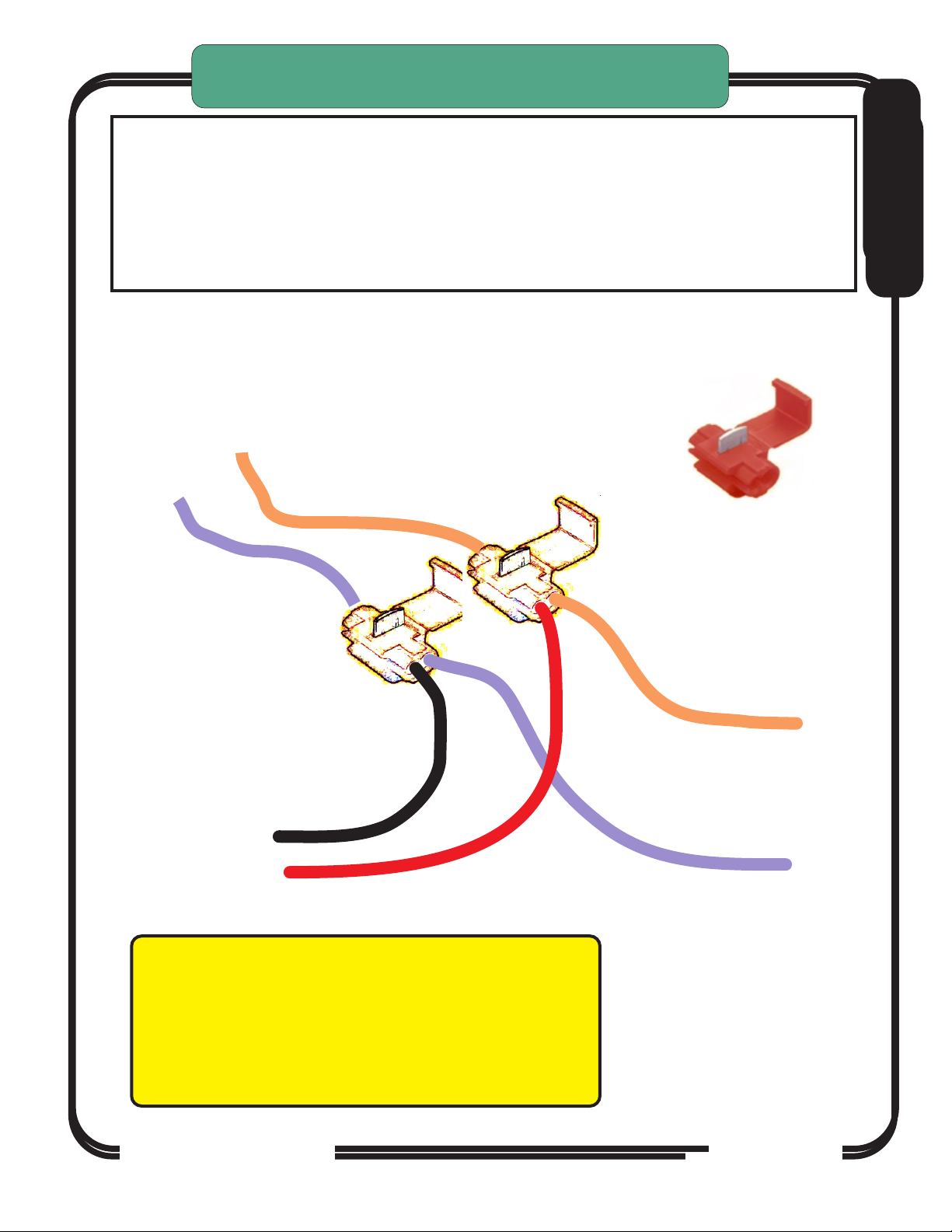
USING THE RAV-01 TO FIRE THE TORCH
(for plasam units with no external connector
to fire the torch or with a hand torch)
NOTE : Some models of plasma cutters that have a CNC connector (CPC
connector) have a safety lockout to prevent firing the hand torch remotely. The
listed connection will fire the torch the same as pulling the trigger. Both the
trigger and the software can fire the torch. There may be a way to bypass the
lock-out and use the CPC connector to fire the torch. Contact us via e-mail for
other possible solutions on plasma cutters that have a CPC connector.
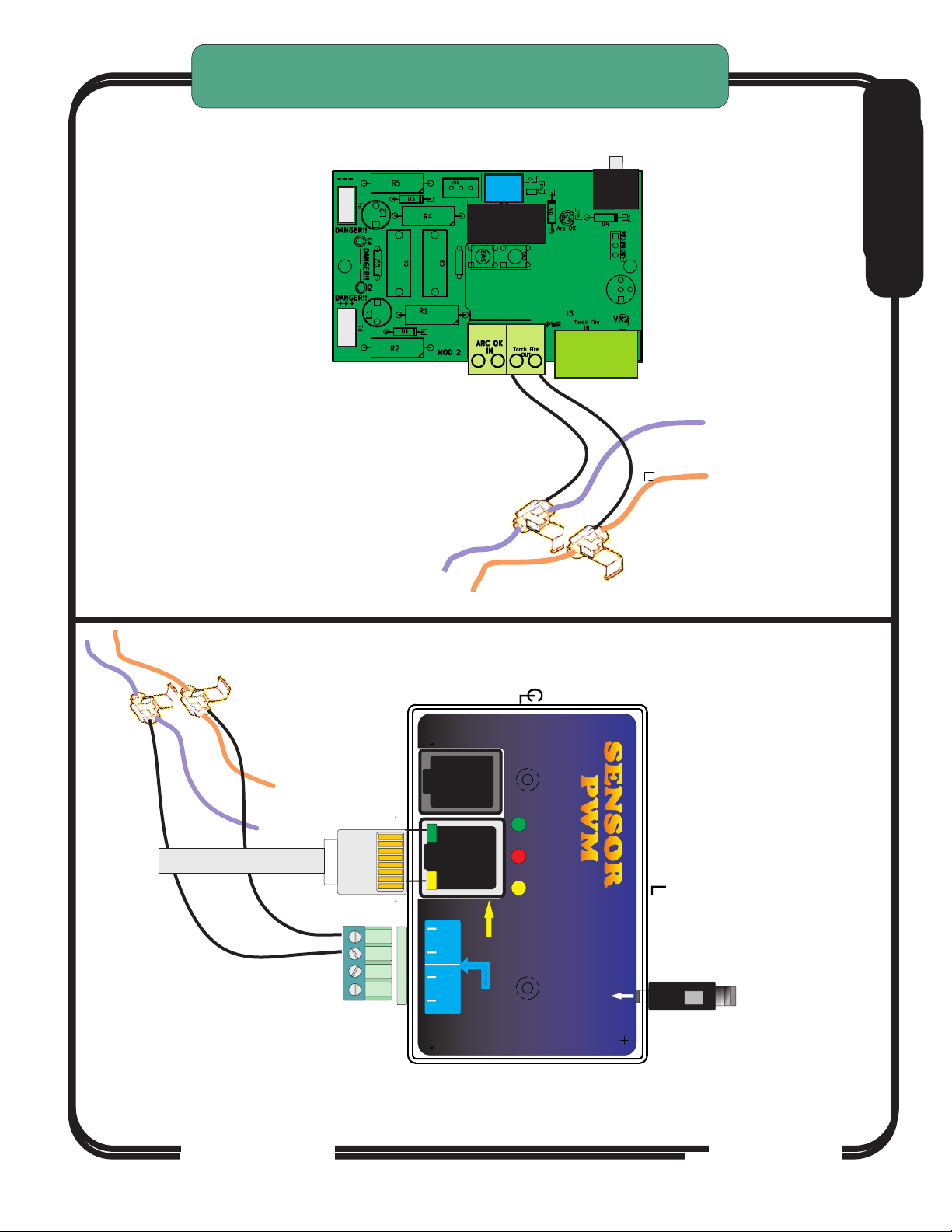
Use ScotchLoc IDC Splices (RED) to tie Torch Switch output on THC Sensor
(J10) Screw Terminals. Locate Orange and Violet wires at J10 in the
PowerMAX box and tap each wire as shown. To test short two screw
terminals on J10 THC Sensor and torch should fire (Plasma Unit on)
CONNECTING HAND TORCH TO THC SENSOR CARD
E
Connect to Screw
terminals J10 1 & 2 on
the THC Sensor Card
IMPORTANT: When making any connection inside
the Plasma Unit, disconnect the unit from the AC
Line (unplug it). Do not open the case with power
on the AC line. THERE ARE DANGEROUS
VOLTAGES present in the unit anytime it is connected
to an AC source EVEN IF IT IS TURNED OFF.
Wire colors will vary
by brand
FROM HAND TORCH CABLE
CandCNC
CandCNC
Page 19
Page 20
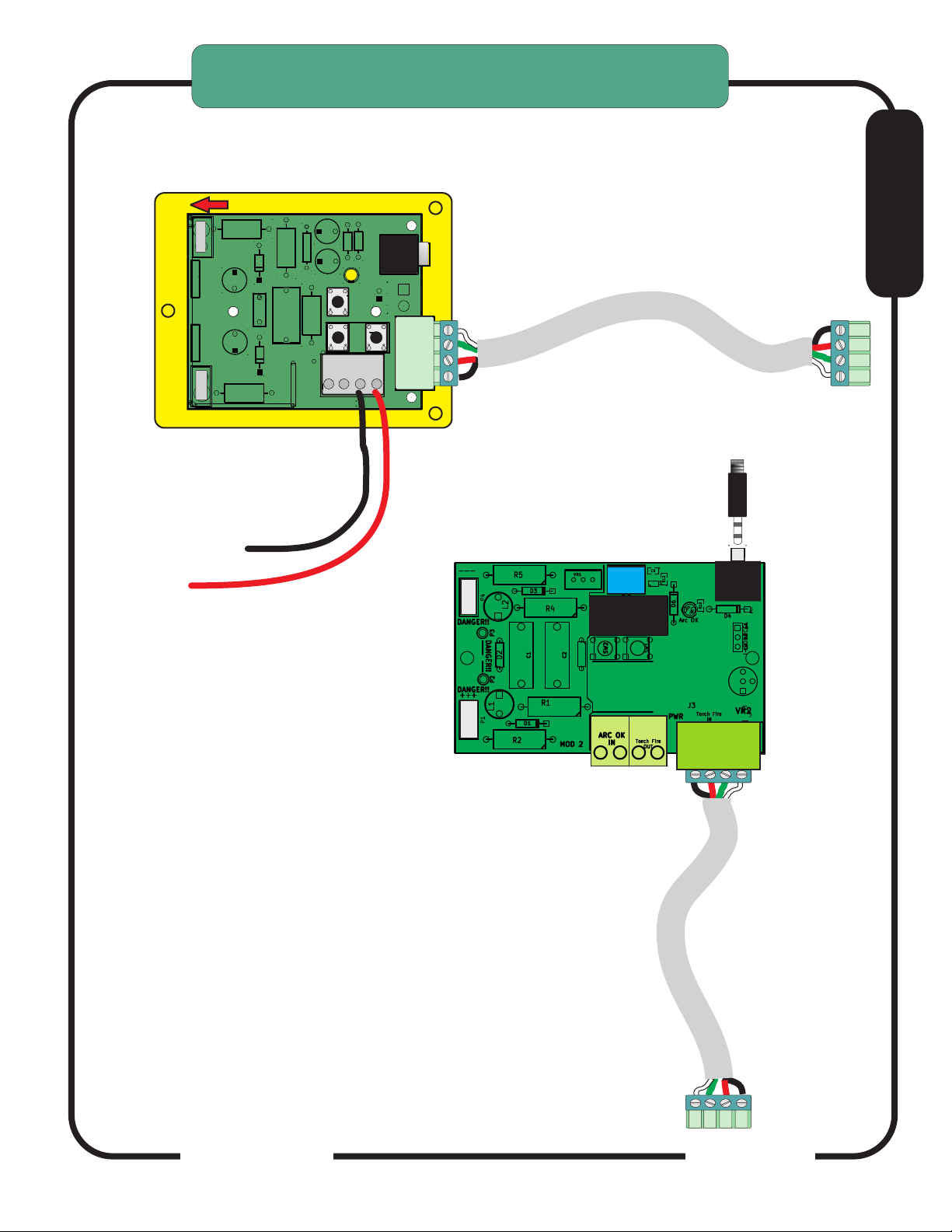
USING THE RAV-01 TO FIRE THE TORCH
(for plasam units with no external connector
to fire the torch or with a hand torch)
NOTE the RAV-01 Card has been updated and designated the RAV-02. Its functions and
connections remain the same but some locations for connectiosn have been moved. Any
reference to the RAV-01 on new systems should be replaced with the RAV-02
RAV-01 Raw Arc Volts CARD
CONNECTION (+)
TO WORKCLAMP
TO ELECTRODE
CONNECTION (-)
CAUTION: High Voltages Present
When TORCH is ON.
CAUTION: High Voltages Present
When TORCH is ON.
J15
Tip
Volts
Workclamp
+ [POS]
CAUTION!
- [NEG]
Tip
Electrode
J14
HIGH VOLTAGE
WHEN TORCH is ON
Volts
D13
CAUTION!
HIGH VOLTAGE
CAUTION!
R1
HIGH VOLTAGE
C1
REV 18
THC
CandCNC
L2
R6
PICKUP
PLASMA
4
ARC
OK
Volts
1
1
SW1
MANUAL
SW3
1
1
Local Connections
3
ARC OK
Out
VOUT
TORCH FIRE
FIRES
CAUTION
2
TORCH SWITCH
TORCH
SWITCH
TORCH
Volts
Divided
+
Divided
-
TP1
+
+
-
TP2
-
SW2
ARC OK
1
TORCH SWITCH
1
Module
Volts
to Torch Sensor PWM
SAC-01 Shieilded Cable
J5
1
1
TO THC SENSOR PWM
TO THC SENSOR PWM
MODULE use CCAB-31
PART # CCAB-31
E
1
Torch Fire wires
see previous page for
connecting to Hand torch
models without CPC
connectors
Electrode (-)
WORK clamp (+)
The RAV-01 card has been
redesigned but the connection points
are the same and similar in location.
Later version RAV-02
Torch
ARC OK
Switch
PAIR
Pair
Divided Volts OUT
to PWM Module
3.5mm stereo plug
1
CandCNC
PART # CCAB-31
1
Page 20
Connection to THC SENSOR PWM
Module
Page 21
USING THE RAV-01 TO FIRE THE TORCH
(for plasam units with no external connector
to fire the torch or with a hand torch)
RAV-02 Raw Arc Volts CARD
Later version RAV-02
RAV-02
CONNECTING TO HAND TORCH SWTICH
WIRES FROM RAV-01
E
SWITCH WIRES FROM
PLASMA HAND PIECE
RJ45 (Cat5) cable to
DTHCIV Module
Use the same two wires on the 4 pin connector for
the PWM Module REV 21
ALTERNATE METHOD TO FIRE HAND TORCH IF NOT
USING RAV-01 CARD
Digital Plasma Module
To DCP-01
SENSORSENSOR
PWM PWM
CandCNC
To DTHC
Module
+5
ON
Active
Torch
Test
Divided Volts
Input JACK
+12 PWR
Arc OK
1
ARC OK
SWITCH
TORCH
(Transfer)
Arc OK
To Plasma
Cable
Volts card
CandCNC
CandCNC
Page 21
Page 22
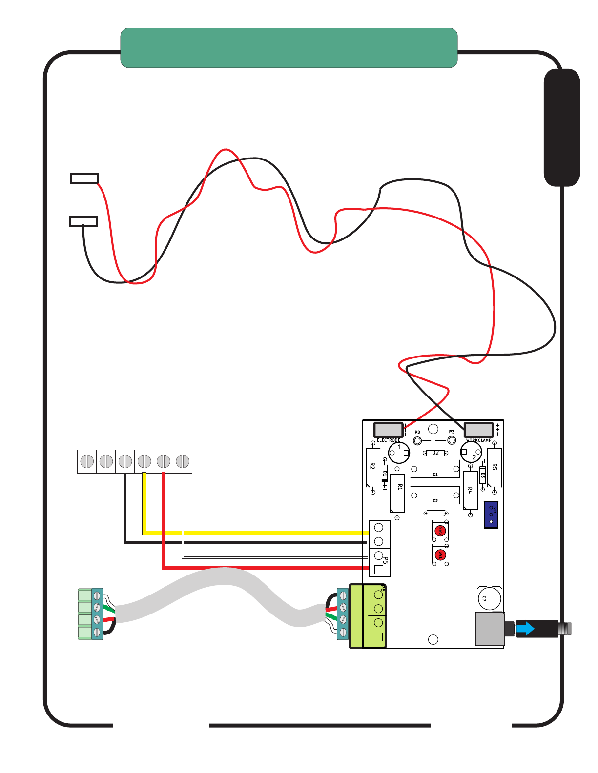
HYPERTHERM 1000/1250/1650
Connecting THC SENSOR PWM CARD
J15
J16
This is for units with a hand torch that do not have the rear CPC connector
TIP VOLTS CONNECTION
J15 and J16 are Slide-on connectors located on the PCB
+
-
Use 18 or 20ga insulated hookup wire
insulation rating to 400V minimum.
F
J19 Located inside Cabinet on PC Board
YEL
BLK
RED
WHT
ARC XFR
START SIGNAL
1
PART # CCAB-31
To PWM Module
Connect to THC SENSOR PWM VIA
CAB-31 Cable
internal
connections
RAV-02
To TORCH (ELECTRODE WIRES)
Arc OK
Torch
Fire
1
Arc OK
Torch
Fire
(THC SENSOR Rev17)
RAV-02 Version
DANGER
HIGH VOLTAGE
WHEN TORCH
is ON
V
MO
R3
Test
Test
Volts Cal
Arc OK
Torch Fire
DIVIDED
VOLTS OUT
Apprx 7:1
Stereo cable to PWM module
To PWM
CandCNC
Page: 75
Page 22
Page 23
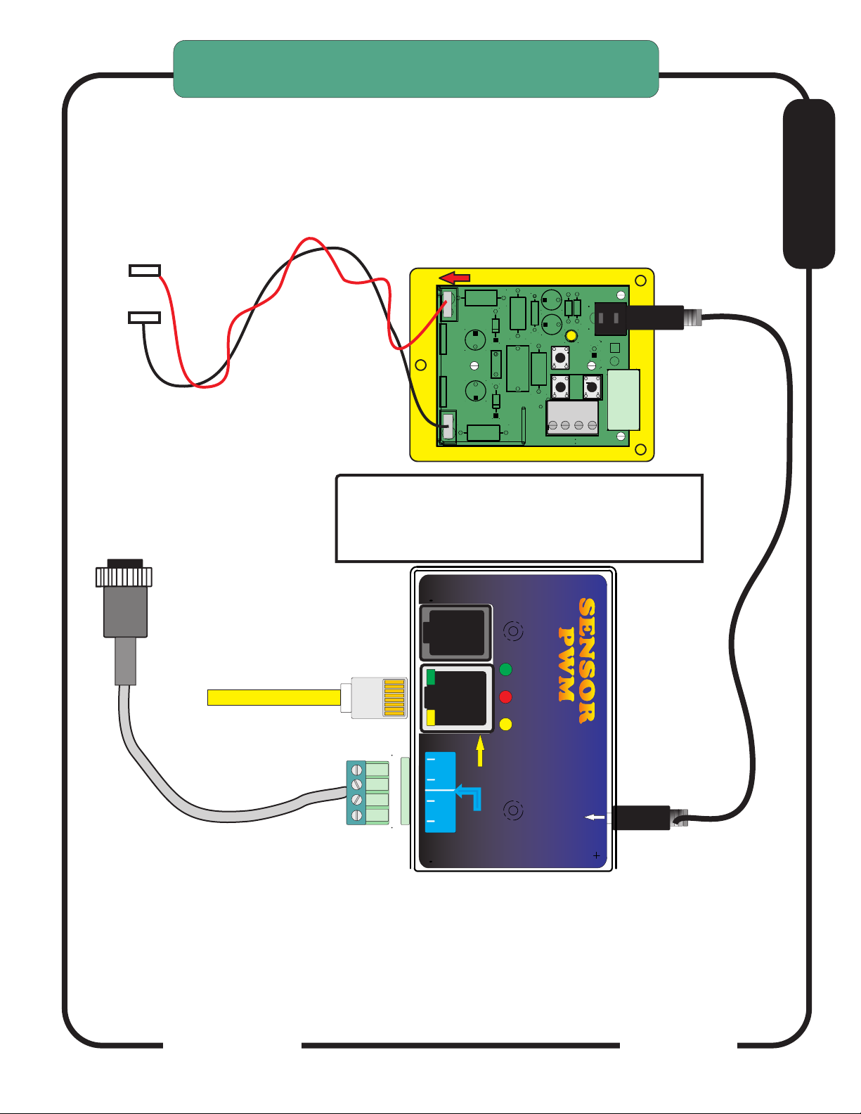
HYPERTHERM 1000/1250/1650 and Thermal Dynamics units
with rear CPC connector and no Arc Voltage Divider
Raw arc volts connection points
vary from one model to another.
Refer to manufacturers manuals
for locations.
+
-
Use 18 or 20ga insulated hookup wire.
Insulation rating to 400V minimum.
OPTIONAL RAV-02
MOUNTED INSIDE PLASMA
CONNECTION (+)
TO WORKCLAMP
TO ELECTRODE
CONNECTION (-)
CAUTION: High Voltages Present
When TORCH is ON.
CAUTION: High Voltages Present
When TORCH is ON.
J15
Tip
Volts
Workclamp
+ [POS]
CAUTION!
- [NEG]
Tip
Electrode
J14
HIGH VOLTAGE
WHEN TORCH is ON
Volts
D13
R1
CAUTION!
C1
HIGH VOLTAGE
REV 18
CAUTION!
HIGH VOLTAGE
CandCNC
THC
PLASMA
L2
MANUAL
R6
PICKUP
4
ARC OK
ARC
OK
Volts
Out
1
1
VOUT
SW1
TORCH FIRE
SW3
1
1
CAUTION
Local Connections
3
TORCH SWITCH
TORCH
SWITCH
FIRES
2
TORCH
F
Volts
Divided
+
Divided
TP1
+
+
-
TP2
-
SW2
ARC OK
1
TORCH SWITCH
1
Volts
-
to Torch Sensor PWM
SAC-01 Shieilded Cable
J5
1
TO THC SENSOR PWM
TO THC SENSOR PWM
MODULE use CCAB-31
Module
Route shielded cable
through rear bulkhead
TO CPC CONNECTOR ON REAR
OF PLASMA
MIC-02
For units with CPC but NO
Internal Voltage Divider
RJ45 (Cat5) cable to
DTHCII Module
METHOD TO CONNECT TO UNIT
WITH MACHINE TORCH USING
REAR CPC CONNECTOR FOR
TORCH FIRING AND ARC OK
Digital Plasma Module
To DCP-01
SENSORSENSOR
PWM PWM
CandCNC
+5
Torch
ON
Active
Test
ARC OK
SWITCH
TORCH
(Transfer)
Arc OK
1
To Plasma
Cable
To DTHC
Module
Divided Volts
Input JACK
Divided volts from
CandCNC Raw Arc
Volts card
CandCNC
Page 23
Page 24
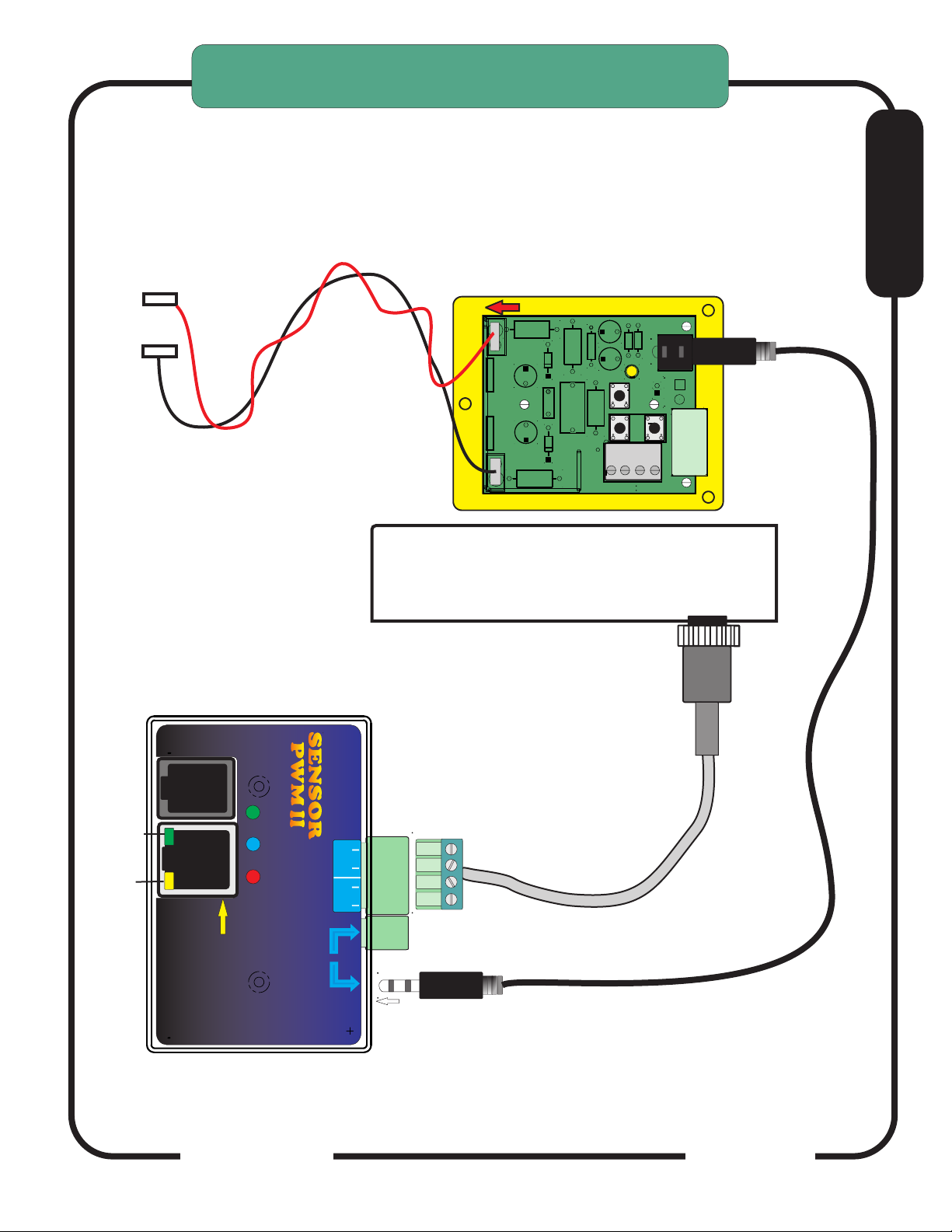
HYPERTHERM 1000/1250/1650 and Thermal Dynamics units
with rear CPC connector and no Arc Voltage Divider
Raw arc volts connection points
vary from one model to another.
Refer to manufacturers manuals
for locations.
+
-
Use 18 or 20ga insulated hookup wire.
Insulation rating to 400V minimum.
OPTIONAL RAV-02
MOUNTED INSIDE PLASMA
CONNECTION (+)
TO WORKCLAMP
TO ELECTRODE
CONNECTION (-)
CAUTION: High Voltages Present
When TORCH is ON.
CAUTION: High Voltages Present
When TORCH is ON.
J15
Tip
Volts
Workclamp
+ [POS]
CAUTION!
- [NEG]
Tip
Electrode
J14
HIGH VOLTAGE
WHEN TORCH is ON
Volts
D13
R1
CAUTION!
C1
HIGH VOLTAGE
REV 18
CAUTION!
HIGH VOLTAGE
CandCNC
THC
PLASMA
L2
MANUAL
R6
PICKUP
4
ARC OK
ARC
OK
Volts
Out
1
1
VOUT
SW1
TORCH FIRE
SW3
1
1
CAUTION
Local Connections
3
TORCH SWITCH
TORCH
SWITCH
FIRES
2
TORCH
F
Volts
Divided
+
Divided
TP1
+
+
-
TP2
-
SW2
ARC OK
1
TORCH SWITCH
1
Volts
-
to Torch Sensor PWM
SAC-01 Shieilded Cable
J5
1
TO THC SENSOR PWM
TO THC SENSOR PWM
MODULE use CCAB-31
Module
Route shielded cable
through rear bulkhead
+12 PWR
Arc OK
To DCP-01
ARC OK
Digital Plasma
Module
CandCNC
To DTHC
Module
+5
ACT
ON
Volts IN
Torch
SENSORSENSOR
PWM PWM
IIII
(Transfer)
To Plasma
Cable
SWITCH
Divided Volts
Input JACK
Arc OK
TORCH
METHOD TO CONNECT TO UNIT
WITH MACHINE TORCH USING
REAR CPC CONNECTOR FOR
TORCH FIRING AND ARC OK
TO CPC CONNECTOR ON REAR
OF PLASMA
MIC-02
For units with CPC but NO
Front
Internal Voltage Divider
T
o CPC or RAV-02
1
CandCNC
Divided volts from
CandCNC Raw Arc
Volts card
Page 24
 Loading...