

Page 1
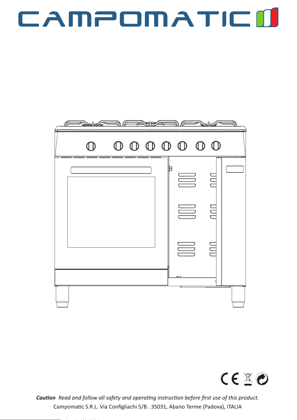
CB95W / CB95GX
Freestanding Cooker
INSTRUCTION MANUAL
:
WWW.CAMPOMATIC.COM
Page 2
1.INSTRUCTIONS FOR USE
……………………………………………………………2-3
2.INSTRUCTIONS FOR DISPOSAL OUR ENVIRONMENTAL CARE…………… …4
3.INSTALLING THE APPLIANCE………………………………………………………5
3.1 Electrical connection………………………………………………………………6
3.2 Room ventilation ………………… ………………………………………………6
3.3 Extraction of the products of combustion … ………………………………………6
3.4 Connection to gas …………………………………………………………………7
4. ADAPTATION TO DIFFERENT TYPES OF GAS ……………………………………8
4.1 Replacement of nozzles on the cooking hob ……………………………………8
4.2 burner and nozzle characteristics table(60CM.model) ………………………9-10
4.3 burner and nozzle characteristics table(90CM.model) ………………………9-10
4.4 Arrangement of the burners on the cooking hob( ………………60CM.model) 11
4.5 Arrangement of the burners on the cooking hob( ………………90CM.model) 11
5. FINAL OPERATIONS …………………………………………………………………12
5.1 Regulation of the hob burners minimum for natural gas ………………………12
5.2 Regulation of the hob burners minimum for Liquid gas ………………………12
5.3 Positioning and levelling the appliance (depending on the model) …………12
5.4 Adjustment of the oven burner minimum ………………………………………12
6. CONTROL PANEL ……………………………………………………………………13-14
7. USING THE COOKING HOB …………………………………………………………15
7.1 Lighting the hob burners …………………………………………………………15
7.2 Practical hints for using the hob burners ………………………………………15
7.3 60 cm and 90cm cooker pan diameters ………………………………………16
8. USING THE OVEN ……………………………………………………………………17
8.1 Warnings and general advice ……………………………………………………17
8.2 Using the gas oven…………………………………………………………………17
8.3 Using the electric grill ……………………………………………………………18
8.4 Storage compartment (only on some models) …………………………………18
9. AVAILABLE ACCESSORIES …………………………………………………………19
10. CLEANING AND MAINTENANCE … ………………………………………………20
10.1 Ordinary daily cleaning … ………………………………………………………20
10.2 Cleaning the parts of the cooking hob ……………………………………20-21
10.3 Cleaning the oven ………………………………………………………………21
10.4 Cleaning the door glazing ………………………………………………………21
11. EXTRAORDINARY MAINTENANCE ………………………………………………22
11.1 Lubrication of gas oven taps and thermostat …………………………………22
11.2 Changing the light bulb …………………………………………………………22
11.3 Removing the doors … …………………………………………………………22
11.4 Removing seal the doors ………………………………………………………22
1
Page 3
TO REPLACE IT.
2
Page 4
1)Appliance type:Class 2
2)Warning the user against the use of cooking vessels on the hotplate that overlap its edges.
3)This appliance shall be installed in accordance with the regulations in force and only used in
a well ventilated space.Read the instructions before installing or using this appliance.
3
Page 5
4
Page 6
1
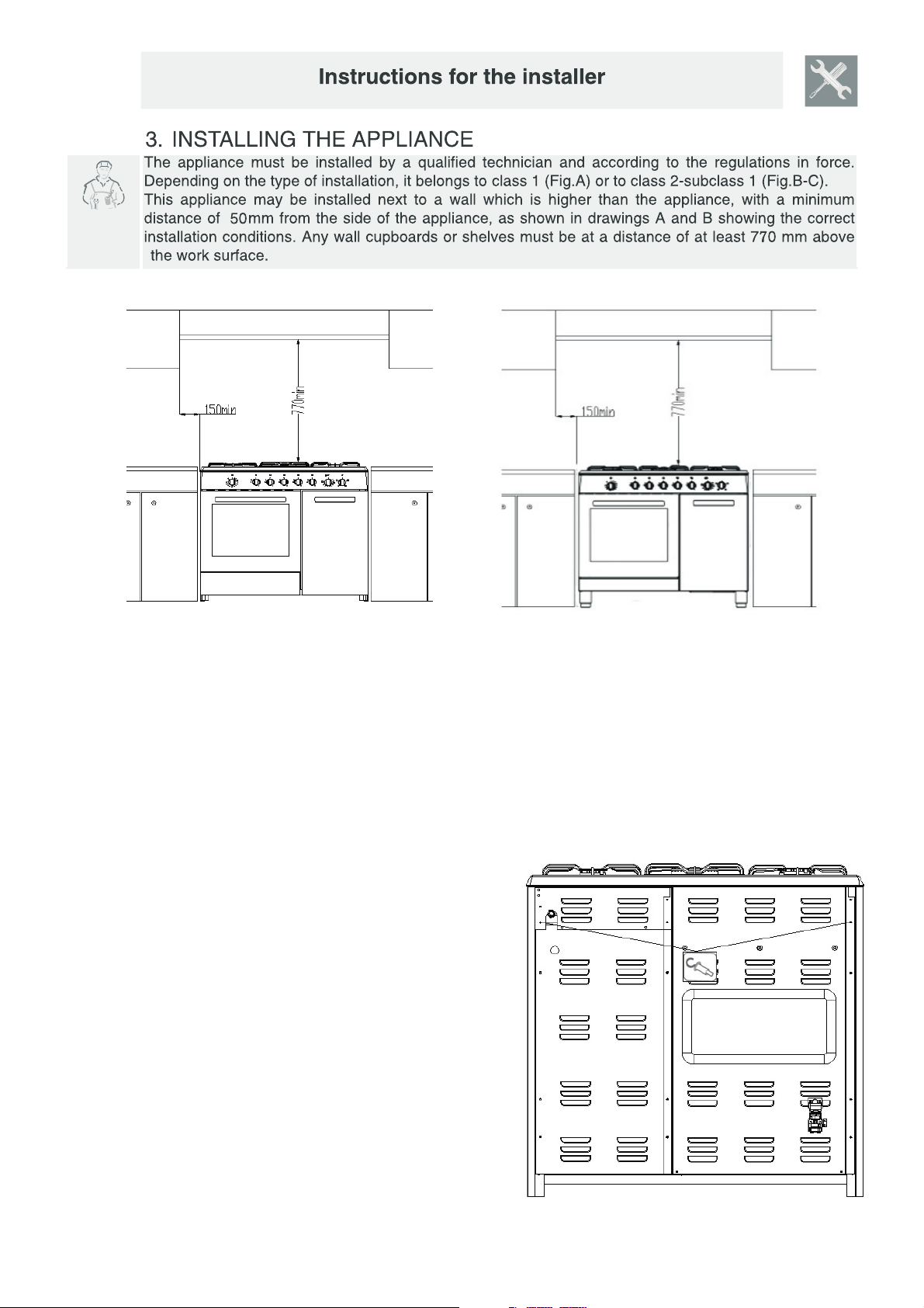
A) Built-in appliance
The cooker is supplied with an anti-tilting chain to prevent th
appliance from tilting forward and accidental damage to the gas
pipe. Take the expansion with hook and make an adequate hole in
the wall behind, at the same height as the chain fixing area. I
the plug into the hole and then screw in the hook until it is f
fixed to the wall. Fix the chain to the hook. Adjust to level o
cooker inserting the feet provided.
5
Page 7
E
Warning:
1)Piror to installation ensure that the local distribution conditions(nature of the gas and gas
pressure)and the adjustment of the appliance are compatible;
2)The adjustment conditions for this appliance are stated on data plate;
3)This appliance is not connected to a combustion products evacration device.It shall be
installed and connected in accordance with current installation regulations.Particular attention
shall be given to the relevant requirements regarding ventilation.
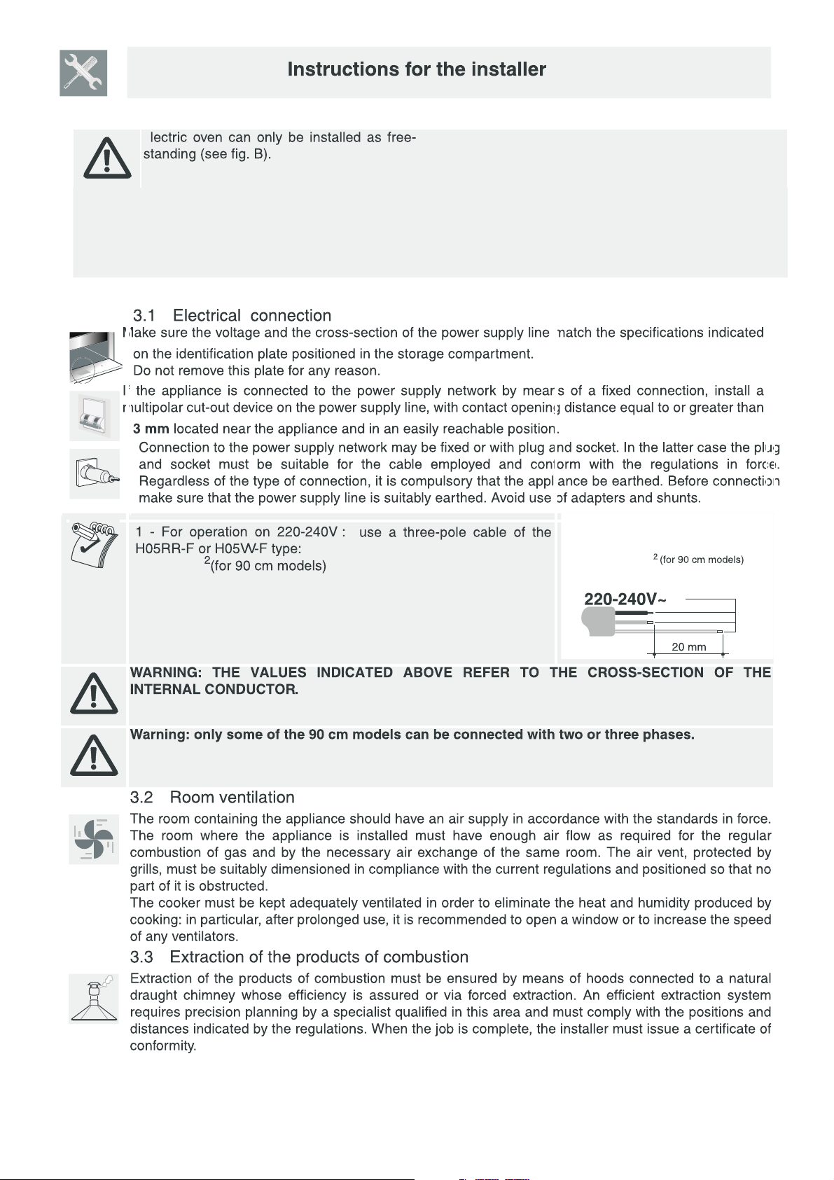
3 X 1.0 mm
3 X 1.0 mm
6
Page 8

steel
length is no
moving parts or is
It’s necessity of changing the flexible tube when the national conditions require it.
Gas
steel
steel
3.4.2
steel
steel
steel
steel
steel hose
steel
steel
degree C).
1.5
7
Page 9

8
Page 10

2
tics table(90 cm.model);
Marking 0.65 on the injector indicates that the size of
injector is 0.65mm
With dry gas and with greater calorific power (Hs ) at 15 and 1013.26 mbar
n
Model
F96A5TMSG2S1
F96A5TMSG2S1-D
F96A5TLSG2S1
F96A5TLSG2S1-D
F96A5T2SG2S1
F96A5T2SG2S1-D
F96A5T3SG2S1
F96A5T3SG2S1-D
F96A4TSG2S1
F96A4TSG2S1-D
F96A3TSG2S1
F96A3TSG2S1-D
F96A3T2SG2S1
F96A3T2SG2S1-D
TOTAL EAT NPUT
H
:I
15.7kW
15.7kW
15.7kW
15.7kW
16.4kW
16.4kW
19.1kW
19.1kW
14.8kW
14.8kW
13.05kW
13.05kW
15.75kW
15.75kW
(1143.2g/h)
s
(1139.6g/h)
(1139.6g/h)
(1139.6g/h)
(1139.6g/h)
(1190.4g/h)
(1190.4g/h)(1190.4g/h)
(1386.4g/h)
(1386.4g/h)
(1074.3g/h)
(1074.3g/h)
(947.3g/h)
(947.3g/h)
(1143.2g/h)
(H
:(Q
)
9
Page 11

4.3
4.4
1.Rapid
2
2
4
1
3
3.Auxiliary
4.Triple ring
10
4.4.1
Page 12

4.4.2
℃
120
150
180
210
260
240
11
Page 13

120
260
120
260
120
260
120
260
℃
12
Page 14

260.
120
120.
10
20
30
120
110
100
90
80
40
50
60
70
℃
℃
120
150
150
180
180
210
210
260
240
240
120
150
180
℃
260
210
240
13
Page 15

14
Caution:Glass lids may shatter when heated.Turn off all the burners before shutting the lid
Page 16

7.3
90cm cooker pan diameters
Container able se lat ottomed aucepans
(u
t
-b
f
s
)
Burner
Auxiliary
Semi-rapid
Fish pan
Rapid
Triple ring
φmin Saucepan
(mm)
90
130
310× 140
150
210
φmax Saucepan
(mm)
160
180
380× 230
260
260
15
Page 17

8.2
8.2.1
265
,
℃
120
150
180
210
240
8.2.2
The use of a gas cooking appliance results in the production of heat and moisture in the room in
which it is installed.Ensure that the kitchen is well ventilated:keep natural ventilation holes open
or install a mechanical ventilation device(mechanical extractor hood).
Prolonged intensive use of the appliance may call for additional ventilation,for example opening
of a window, or more effective ventilation,for example incressing the level of mechanical
ventilation where present
260
16
Page 18

8.3
℃
120
150
180
210
260
240
8.4
17
Page 19

181920
Page 20

Page 21

Page 22

11.2
3
2
1
Cleaning the oven do or
11.3 Removing the doors.
For a more thorough clean,you have to remove the oven door.Choose the removal and assemble method
according to different structure of oven door purchased.
Proceed as follows:
Open the door fully;
Lift up and turn the small levers located on the two hinges;
Grip the door on the two external sides and close it approximately half way.Unlock the door by pressing
on
the clamps F,then pull the door towards you lifting it out of its seat.To replace the door,reverse this
sequence.
11.4
21
 Loading...