

Page 1
Electric Air Compressor
Operating Instructions and Parts Manual
© 2018 Campbell Hausfeld
A Marmon/Berkshire Hathaway Company
Models: CE5002 and XC602100
EN
IN573900 10/18
Page 2

Please read and save these instructions. Read carefully before attempting to
assemble, install, operate or maintain the product described.
Protect yourself and others by observing all safety information. Failure to comply
with instructions could result in personal injury and/or property damage! Retain
instructions for future reference.
REMINDER: Keep your dated proof of purchase for warranty purposes! Attach it to
this manual or file it for safekeeping.
For parts, product & service information
Model #: __________________________
Serial #: ___________________________
Purchase Date: _____________________
REGISTER YOUR PRODUCT ONLINE NOW! www.campbellhausfeld.com/reg
READ AND FOLLOW ALL INSTRUCTIONS • SAVE THESE INSTRUCTIONS • DO NOT DISCARD
visit www.campbellhausfeld.com
Campbell Hausfeld
100 Production Drive
Harrison, Ohio 45030
Page 3
BEFORE YOU BEGIN
Description
Air compressor units are intended to provide compressed air to power pneumatic tools, operate spray guns
and supply air for pneumatic valves and actuators. The pumps supplied with these units have oil lubricated
bearings. A small amount of oil carryover is present in the compressed air stream. Applications requiring air
free of oil vapor should have the appropriate filters installed. The air compressor units are to be mounted
per the instructions provided on a solid floor. Any other use of these units will void the warranty and the
manufacturer will not be responsible for problems or damages resulting from such misuse.
QUICK REFERENCE
Recommended Oil (2 Options)
Single viscosity SAE 30 ISO100 nondetergent compressor oil. Part number ST125303AV (0.5
qt) or ST126701AV (4 qt).
10W30 synthetic oil such as Mobil 1® or CE0032 (1 qt).
Oil Capacity
Approximately 47.4 oz.
SPECIFICATIONS
SAFETY /
UNPACKING
Do not lift or move unit without appropriately rated equipment. Be sure the unit is securely
to lift other attached equipment.
After unpacking the unit, inspect carefully for any damage that may have occurred during transit. Check for
loose, missing or damaged parts. Check to be sure all supplied accessories are enclosed with the unit. In case
of questions, damaged or missing parts, please visit www.campbellhausfeld.com for customer assistance.
Do not operate unit if damaged during shipping, handling or use. Damage may result in
Required Items - Not Included
• Oil
• Concrete anchors
• Isolation pads
• Isolation valve
• Power cord/electrical disconnect
attached to lifting device used. Do not lift unit by holding onto tubes or coolers. Do not use unit
bursting and cause injury or property damage.
INSTALLATION
ASSEMBLY /
TROUBLESHOOTINGOPERATION
MAINTENANCE /
REPAIR
1
Page 4
GENERAL SAFETY INSTRUCTIONS
Safety Guidelines
This manual contains information that is very important to know and understand. This information is
provided for SAFETY and to PREVENT EQUIPMENT PROBLEMS. To help recognize this information, observe
GETTING STARTED
the following symbols.
Danger indicates an imminently hazardous situation which, if not avoided, WILL result in death
Warning indicates a potentially hazardous situation which, if not avoided, COULD result in
Caution indicates a potentially hazardous situation which, if not avoided, MAY result in minor or
or serious injury.
death or serious injury.
moderate injury.
SAFETY /
ASSEMBLY /
SPECIFICATIONS
INSTALLATION
Notice indicates important information, that if not followed, may cause damage to equipment.
IMPORTANT or NOTE: Information that requires special attention.
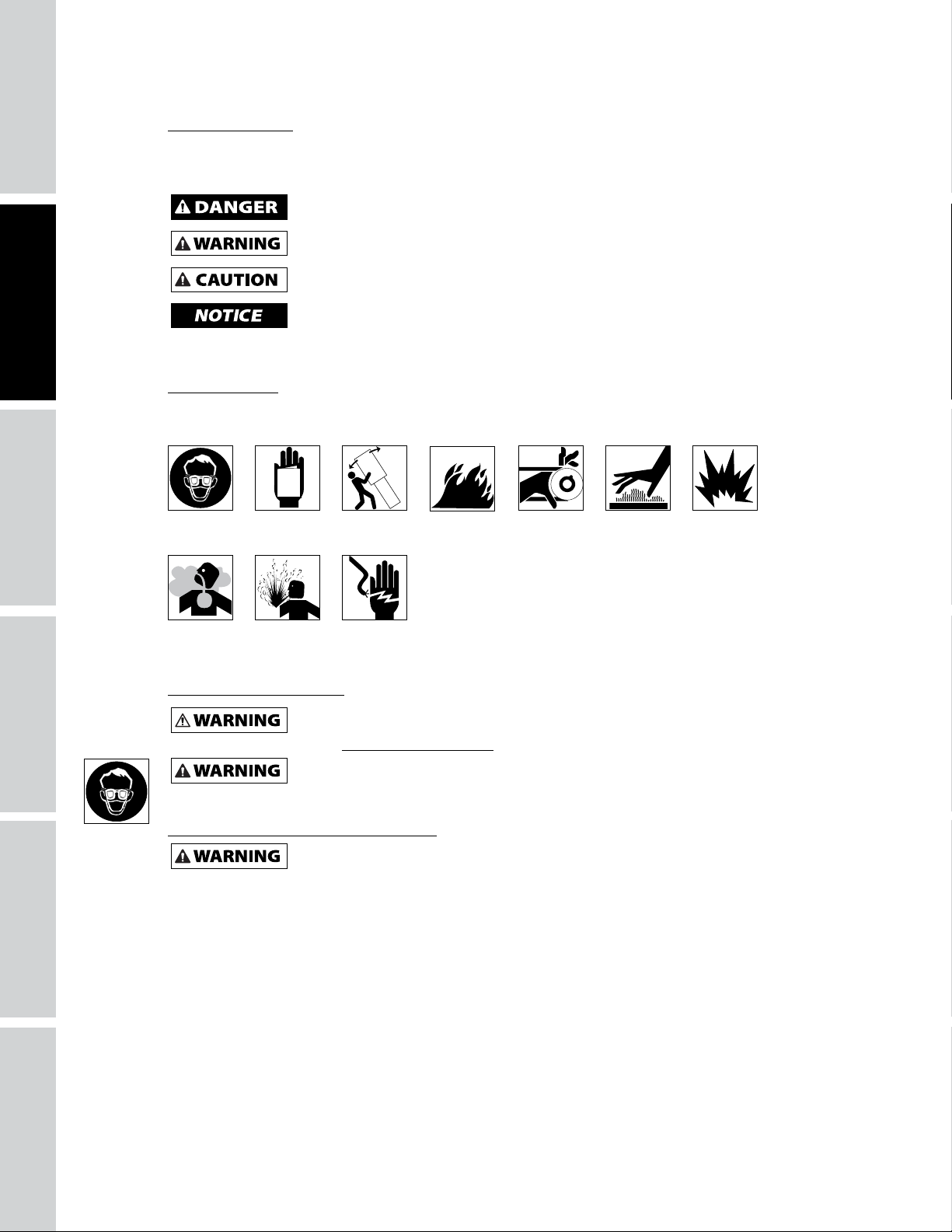
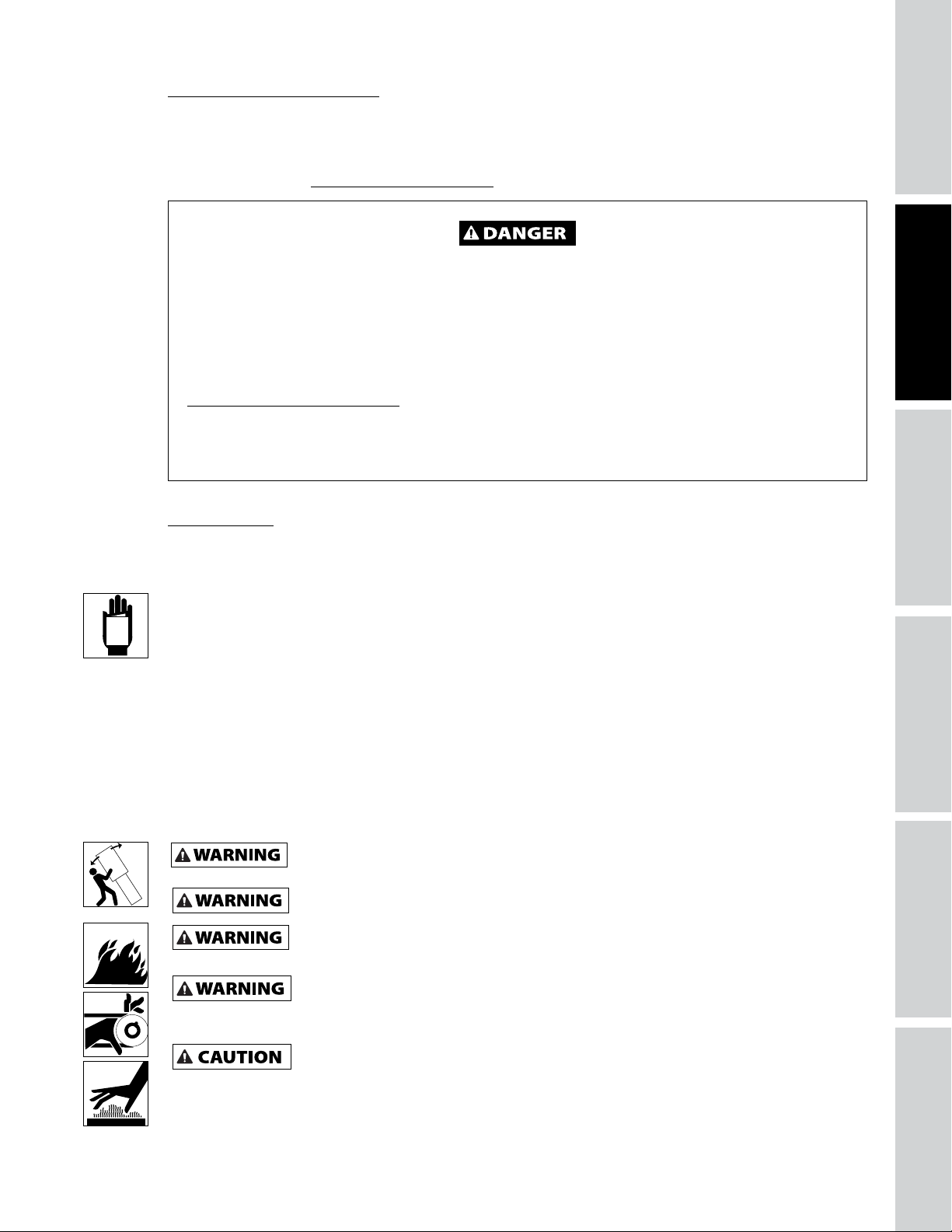
Safety Symbols
The following Safety Symbols appear throughout this manual to alert you to important safety hazards and
precautions.
MANUAL
Wear Eye
and Mask
Protection
Risk of
Fumes
Read
Manual
First
Risk of
Pressure
Top Heavy Risk of
Risk of Shock
Risk of
Fire
Moving Parts
Risk of
Hot Parts
Risk of
Explosion
California Proposition 65
This product can expose you to chemicals including lead, which are known to the State of
go to www.P65Warnings.ca.gov.
You can create dust when you cut, sand, drill or grind materials such as wood, paint, metal,
birth defects, or other reproductive harm. Wear protective gear.
California to cause cancer and birth defects or other reproductive harm. For more information
concrete, cement, or other masonry. This dust often contains chemicals known to cause cancer,
Illinois Lead Poisoning Prevention Act
CONTAINS LEAD. MAY BE HARMFUL IF EATEN OR CHEWED. COMPLIES WITH FEDERAL
STANDARDS.
2
Page 5
MANUAL
Important Safety Information
Please read and save these instructions. Read carefully before attempting to assemble, install, operate or maintain the
product described. Protect yourself and others by observing all safety information. Failure to comply with instructions
could result in personal injury and/or property damage! Retain instructions for future reference.
This manual contains important safety, operational and maintenance information. If you have any
questions, please visit www.campbellhausfeld.com for customer assistance.
BREATHABLE AIR WARNING
This compressor/pump is not equipped and should not be used “as is” to supply breathing quality
air. For any application of air for human consumption, the air compressor/pump will need to be
fitted with suitable in-line safety and alarm equipment. This additional equipment is necessary to
properly filter and purify the air to meet minimal specifications for Grade D breathing as described in
Compressed Gas Association Commodity Specification G 7.1, OSHA 29 CFR 1910. 134, and/or Canadian
Standards Associations (CSA).
DISCLAIMER OF WARRANTIES
In the event the compressor is used for the purpose of breathing air application and proper in-line
safety and alarm equipment is not simultaneously used, existing warranties shall be voided, and
Campbell Hausfeld disclaims any liability whatsoever for any loss, personal injury or damage.
General Safety
Since the air compressor and other components (material pump, spray guns, filters, lubricators, hoses, etc.)
used make up a high pressure pumping system, the following safety precautions must be observed at all
times:
• Read all manuals included with this product carefully. Be thoroughly familiar with the controls and
the proper use of the equipment.
• Follow all local electrical and safety codes as well as the United States National Electrical Codes (NEC)
and Occupational Safety and Health Act (OSHA).
• Only persons well acquainted with these rules of safe operation should be allowed to use the
compressor.
• Keep visitors away and NEVER allow children in the work area.
• Wear safety glasses and use hearing protection when operating the unit.
• Do not stand on or use the unit as a handhold.
• Before each use, inspect compressed air system and electrical components for signs of damage,
deterioration, weakness or leakage. Repair or replace defective items before using.
• Check all fasteners at frequent intervals for proper tightness.
This compressor is extremely top heavy. The unit must be bolted to the floor with isolation pads
before operating to prevent equipment damage, injury or death.
SPECIFICATIONS
SAFETY /
INSTALLATION
ASSEMBLY /
TROUBLESHOOTINGOPERATION
Never install a shut-off valve between the compressor pump and the tank.
Motors, electrical equipment and controls can cause electrical arcs that will ignite a
store flammable liquids or gases in the vicinity of the compressor.
Never operate compressor without a beltguard. This unit can start automatically without
flammable gas or vapor. Never operate or repair in or near a flammable gas or vapor. Never
warning. Personal injury or property damage could occur from contact with moving parts.
• Do not wear loose clothing or jewelry that will get caught in the moving parts of the unit.
Compressor parts may be hot even if the unit is stopped.
• Keep fingers away from a running compressor; fast moving and hot parts will cause injury and/or
burns.
3
REPAIR
MAINTENANCE /
Page 6
SAFETY /
ASSEMBLY /
GENERAL SAFETY INSTRUCTIONS (CONTINUED)
• If the equipment should start to vibrate abnormally, STOP the engine/motor and check immediately
for the cause. Vibration is generally an indication of trouble.
GETTING STARTED
SPECIFICATIONS
INSTALLATION
• To reduce fire hazard, keep engine/motor exterior free of oil, solvent, or excessive grease.
An ASME code safety relief valve with a setting no higher than 200 PSI MUST be installed in the
protect the pressurized components from bursting.
Maximum operating pressure is 175 PSI for single stage compressors. Do not operate with
tank for this compressor. The ASME safety valve must have sufficient flow and pressure ratings to
See compressor specifications for maximum operating pressure. Do not operate with pressure
switch or pilot valves set higher than the maximum operating pressure.
pressure switch or pilot valves set higher than 175 PSI (2-stage).
• Never attempt to adjust ASME safety valve. Keep safety valve free from paint and other
accumulations.
Never use plastic (PVC) pipe for compressed air. Serious injury or death could
Never attempt to repair or modify a tank! Welding, drilling or any other modification will
or damaged tanks.
result.
weaken the tank resulting in damage from rupture or explosion. Always replace worn, cracked
Drain liquid from tank daily.
• Tanks rust from moisture build-up, which weakens the tank. Make sure to drain tank regularly and
inspect periodically for unsafe conditions such as rust formation and corrosion.
• Fast moving air will stir up dust and debris which may be harmful. Release air slowly when draining
moisture or depressurizing the compressor system.
Spraying Precautions
Do not spray flammable materials in vicinity of open flame or near ignition sources including
• Do not smoke when spraying paint, insecticides, or other flammable substances.
• Use a face mask/respirator when spraying and spray in a well ventilated area to prevent health and fire
hazards.
• Do not direct paint or other sprayed material at the compressor. Locate compressor as far away from
the spraying area as possible to minimize overspray accumulation on the compressor.
• When spraying or cleaning with solvents or toxic chemicals, follow the instructions provided by the
chemical manufacturer.
The DANGER, WARNING, CAUTION, and NOTICE notifications and instructions in this manual cannot
cover all possible conditions and situations that may occur. It must be understood by the operator that
caution is a factor which cannot be built into this product, but must be supplied by the operator.
the compressor unit.
SAVE THESE INSTRUCTIONS
DO NOT DISCARD
4
Page 7

SPECIFICATIONS
CE5002 XC602100
HP 3.5 3.5
Number of Cylinders 2 2
Number of Stages 2 2
Air Delivery @ 90 PSI 11 CFM 11 CFM
Voltage 230 Volts /
16.2 Amps
Max Pressure 175 PSI 175 PSI
Oil Capacity 47.4 ounces 47.4 ounces
Tank Outlet Size 3/4 NPT 3/4 NPT
Weight 270 lbs. 270 lbs.
230 Volts /
16.2 Amps
DIMENSIONS
CE5002 XC602100
Length 21.9 inches 21.9 inches
Width 27.5 inches 27.5 inches
Height 69.6 inches 69.6 inches
SPECIFICATIONS
SAFETY /
INSTALLATION
ASSEMBLY /
TROUBLESHOOTINGOPERATION
MAINTENANCE /
REPAIR
5
Page 8
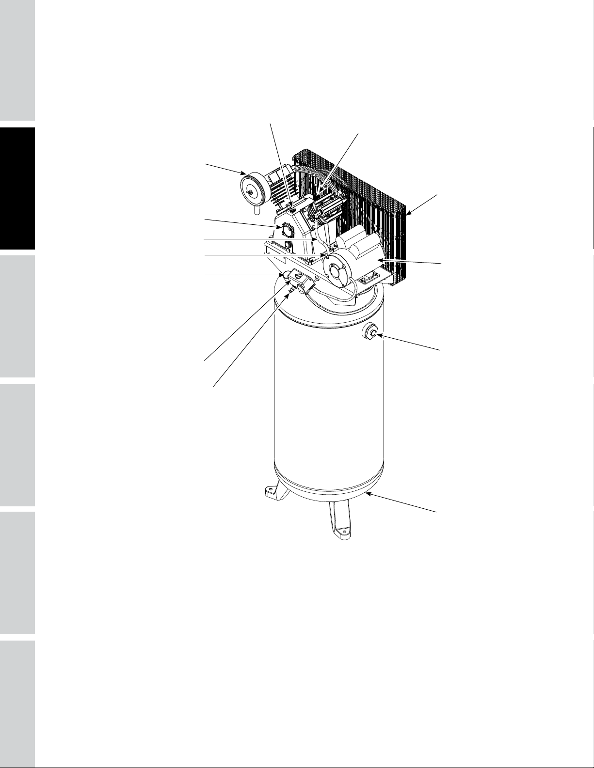
GETTING TO KNOW YOUR UNIT
SAFETY /
ASSEMBLY /
GETTING STARTED
SPECIFICATIONS
INSTALLATION
Oil Fill Port
Breather
Air Filter
Belt Guard
Pump
Discharge Tube
Check Valve
Motor
Tank Pressure Gauge
Tank Outlet
Pressure Switch
ASME Safety Valve
Figure 1 - Unit Identification
Tank Drain Valve
6
Page 9
GETTING TO KNOW YOUR UNIT
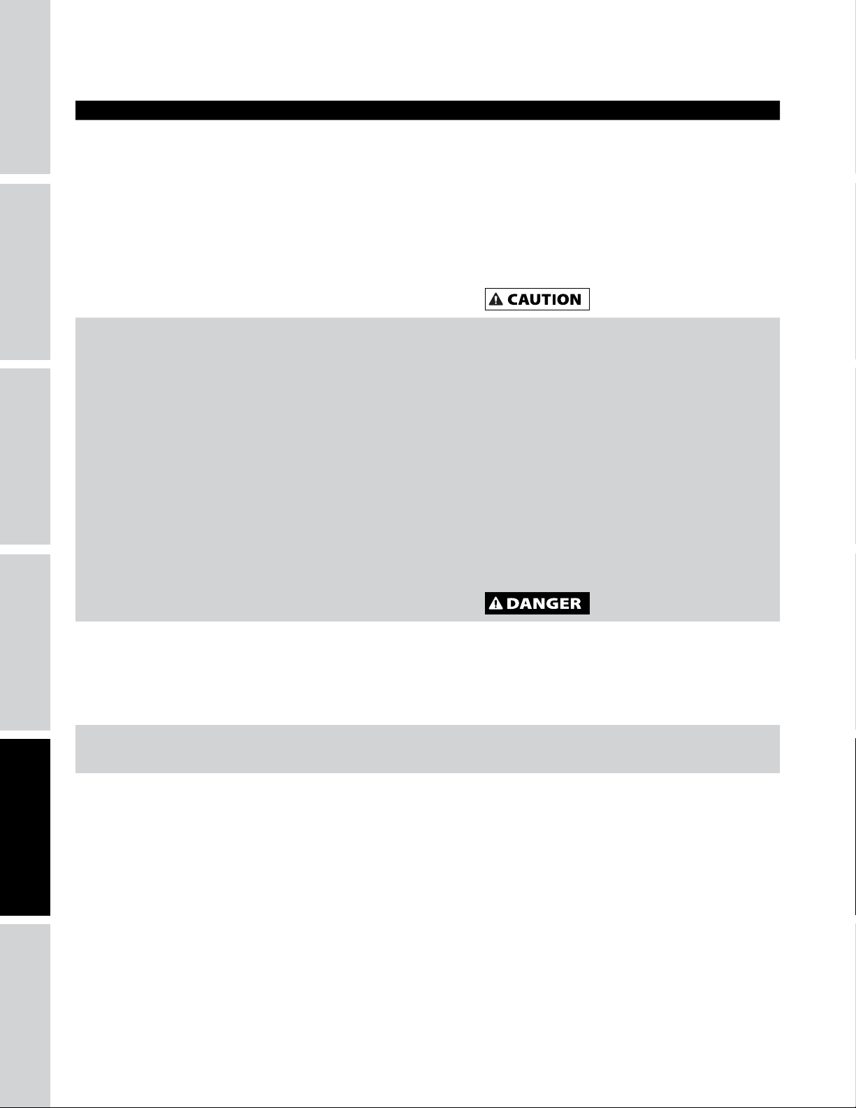
Pressure Switch - Auto/Off Switch - In the auto position, the compressor shuts off automatically when tank
pressure reaches the maximum preset pressure. After air is used from the tank and drops to a preset low
level, the pressure switch automatically turns the motor back on. In the off position, the compressor will not
operate. This switch should be in the off position when connecting or disconnecting the power from the
unit.
When the pressure switch turns the motor off you will hear air leaking out of the pressure switch unloader
valve for a short time. This releases the air pressure from the discharge tube and allows the compressor to
restart easier.
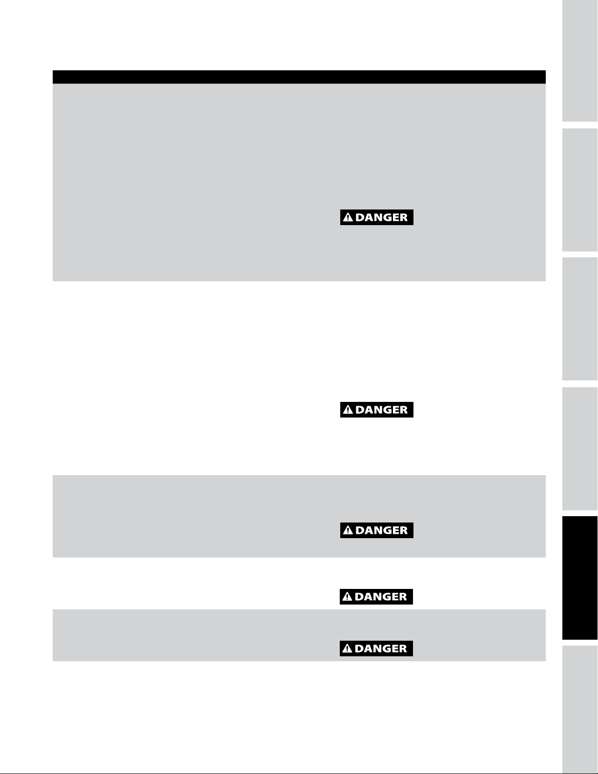
ASME Safety Valve - This valve automatically releases air if the tank pressure exceeds the preset maximum.
Discharge Tube - This tube carries compressed air from the pump to the check valve. This tube becomes very
hot during use. To avoid the risk of severe burns, never touch the discharge tube.
Check Valve - One-way valve that allows air to enter the tank, but prevents air in the tank from flowing
back into the compressor pump.
Belt Guard - Covers the belt, motor pulley and flywheel.
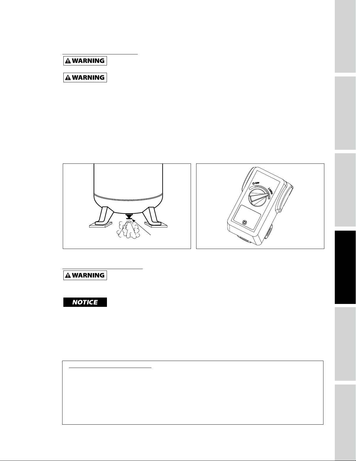
Tank Drain Valve - This valve is located on the bottom of the tank. Use this valve to drain moisture from the
tank daily to reduce the risk of corrosion.
Tank Pressure Gauge - Indicates amount of air pressure stored in tank.
Air Filter - Keeps large particulates out of the air flowing into the compressor.
Breather - Vent for crankcase.
Oil Fill Port - Port used to refill the oil in the pump after oil changes or when oil is low.
SPECIFICATIONS
SAFETY /
INSTALLATION
ASSEMBLY /
Pump - Cast Iron 2-Stage air compressor pump that generates compressed air.
Motor - Power source that drives the pump to create compressed air.
Tank Outlet - This is where you plumb into to get compressed air from the pressure vessel. An isolation
valve should be installed here to be able to shut off the air supply from the tank.
INSTALLATION INSTRUCTIONS
Disconnect, tag and lock out power source then release all pressure from the system before
Do not lift or move unit without appropriately rated equipment. Be sure the unit is securely
to lift other attached equipment.
Preparation
Before beginning installation and/or assembly of product, make sure all parts are present. Compare parts
with package contents list. If any part is missing or damaged, do not attempt to assemble or use the
product.
Do not operate unit if damaged during shipping, handling or use. Damage may result in
Estimated Installation and Assembly Time: 120 minutes
Tools Required for Installation and Assembly (not included): Safety Glasses; Work Gloves; 9/16 in. Socket and
Ratchet; Tape measure; Hammer Drill and Masonry Bit; Hammer; Phillips Screwdriver; Flathead Screwdriver;
Pipe Wrench; Two Adjustable Wrenches; 1/4 in. Nut Driver, Socket or Wrench; 240 Volt, 30 Amp Double Pole
Circuit Breaker; Voltage Meter; Vibration Pads; 3/8 in. x 5 in. Wedge Anchors (for concrete installation).
attempting to install, service, relocate or perform any maintenance.
attached to lifting device used. Do not lift unit by holding onto tubes or coolers. Do not use unit
Never use the wood shipping skids for mounting the compressor.
This compressor is not intended for outdoor installation.
bursting and cause injury or property damage.
TROUBLESHOOTINGOPERATION
MAINTENANCE /
REPAIR
7
Page 10
SAFETY /
INSTALLATION INSTRUCTIONS (CONTINUED)
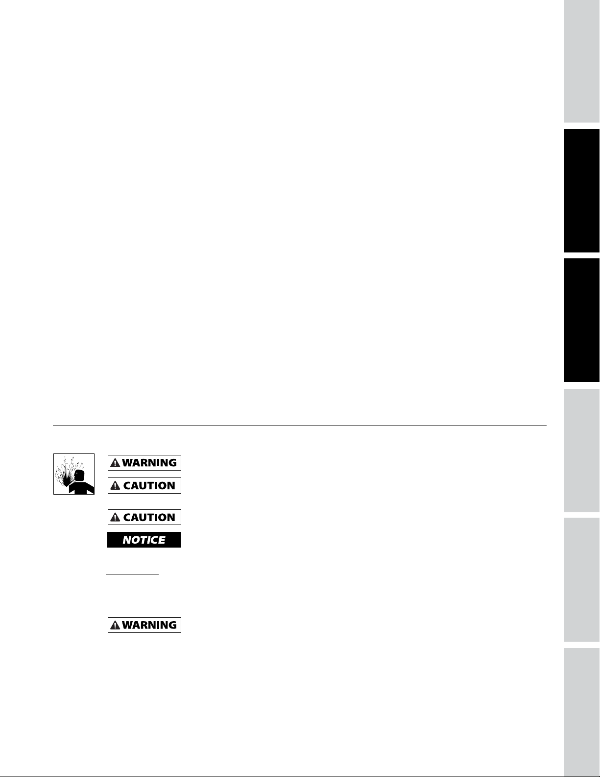
Picking the Location
Install and operate unit at least 18 inches from any
GETTING STARTED
SPECIFICATIONS
obstructions in a clean, well ventilated area. The
surrounding air temperature should not exceed
100° F. This will ensure an unobstructed flow of air
to cool compressor and allow adequate space for
maintenance.
Do not locate the compressor air
inlet near steam, paint spray,
sandblast areas or any other source of contamination.
NOTE: If compressor operates in a hot, moist
environment, supply compressor pump with clean, dry
outside air. Supply air should be piped in from external
sources.
18 inches
18 inches
ASSEMBLY /
INSTALLATION
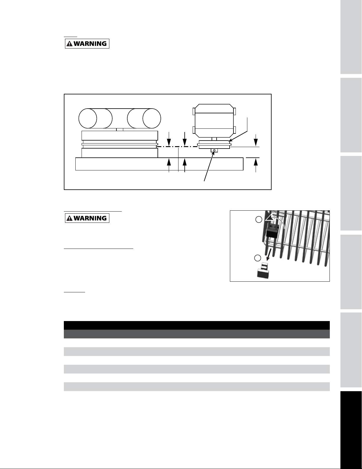
Tank Mounting
The tank should be bolted into a flat, even, concrete
floor or on a separate concrete foundation. Vibration
isolators should be used between the tank leg and
the floor. Model MP345700AJ isolator pads are
recommended for installation.
When using isolator pads, do not draw bolts tight.
Allow the pads to absorb vibrations. When isolators
are used, a flexible hose or coupling should be
installed between the tank and service piping.
Failure to properly install the
tank can lead to cracks at the
welded joints and possible bursting.
1. Unbolt the unit from the shipping skid. Use a
ratchet with a 9/16 in. socket. Remove the unit
from the skid. This requires at least two people one person to walk the unit off the skid and one
to help maintain balance so the unit does not
topple. Place the unit where you plan to install it
(at least 18 in. from any wall or surface).
2. Place pre-drilled vibration pads (sold separately)
under each foot to avoid unnecessary vibration
which could damage the unit.
Using the mounting holes and the holes of the
vibration pads as a guide, drill holes into concrete
using a 3/8 in. masonry bit. Holes drilled must be
at least 5 in. into the concrete.
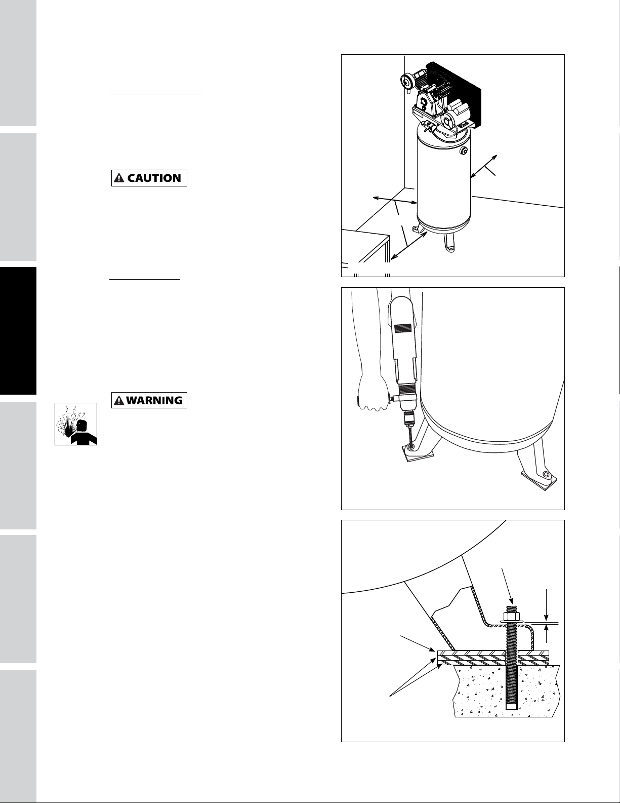
3. Insert mounting bolts. Use 3/8 in. x 5 in. wedge
anchors (not included) to secure the unit. Place
nut and washer on bolt. Thread nut onto bolt
until tops are flush. Strike bolt with hammer
until nut and washer are setting on top of the
compressor foot.
Tighten nut using ratchet with a 9/16 in. socket
until anchor is set (using installation torque
specifications of bolt being used). Loosen nut
to leave a 1/16 in. (1.6 mm) gap for stress relief
during unit operation.
Figure 2
Figure 3
Concrete Anchor
1/16 inch
(1.6 mm)
Metal Plate
Rubber
Pad
Figure 4
8
Page 11
Piping
Any tube, pipe or hose connected to the unit must be able to withstand the temperature generated and
retain the pressure. All pressurized components of the air system must have a pressure rating of 200 PSI or
higher. Minimum recommended pipe size is 3/4 in. Larger diameter pipe is always better. Incorrect selection
and installation of any tube, pipe or hose could result in bursting and injury. Connect piping system to tank
using the same size fitting as the discharge port.
Chart 1
Installing A Shut-Off Valve
Never use plastic (PVC) pipe for compressed air. Serious injury or death could result.
Minimum Pipe Size For Compressed Air Line
LENGTH OF PIPING SYSTEM
CFM
10 1/2 inch 1/2 inch 3/4 inch 3/4 inch
20 3/4 inch 3/4 inch 3/4 inch 1 inch
40 3/4 inch 1 inch 1 inch 1 inch
60 3/4 inch 1 inch 1 inch 1 inch
100 1 inch 1 inch 1 inch 1-1/4 inch
25 FEET 50 FEET 100 FEET 250 FEET
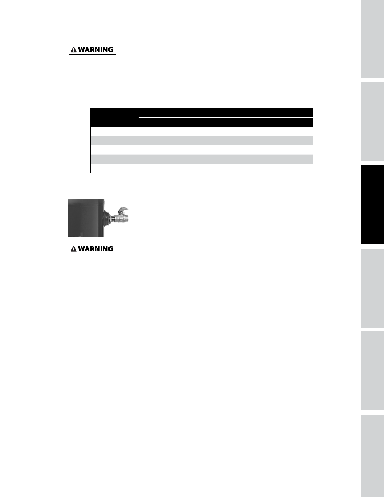
A shut-off valve should be installed on the discharge port of the
tank to control the air flow out of the tank. The valve should be
located between the tank and the piping system.
SPECIFICATIONS
SAFETY /
INSTALLATION
ASSEMBLY /
Figure 5
Never install a shut-off valve between the compressor pump and the tank. Personal injury and/or
equipment damage may occur. Never use reducers in discharge piping.
When creating a permanently installed system to distribute compressed air, find the total length of the
system and select pipe size from Chart 1. Bury underground lines below the frost line and avoid pockets
where condensation can gather and freeze.
Apply air pressure to the piping installation and make sure all joints are free from leaks BEFORE
underground lines are covered. Before putting the compressor into service, find and repair all leaks in the
piping, fittings and connections.
TROUBLESHOOTINGOPERATION
MAINTENANCE /
REPAIR
9
Page 12
INSTALLATION INSTRUCTIONS (CONTINUED)
Wiring
Improperly grounded motors are shock hazards. Make sure all the equipment is properly
GETTING STARTED
All wiring and electrical connections must be performed by a qualified electrician
national codes.
Disconnect, tag and lock out power source, then release all pressure from the system before
grounded.
familiar with induction motor controls. Installations must be in accordance with local and
Overheating, short circuiting and fire damage will result from inadequate wiring.
attempting to install, service, relocate or perform any maintenance.
SAFETY /
ASSEMBLY /
SPECIFICATIONS
INSTALLATION
Damage to the motor from improper electrical voltage or connection will void the warranty.
Wiring must be installed in accordance with National Electrical Code and local codes and standards that
have been set up covering electrical apparatus and wiring. These should be consulted and local ordinances
observed. Be certain that adequate wire sizes are used, and that:
• Service is of adequate ampere rating.
• The supply line has the same electrical
characteristics (voltage, cycles and phase) as
the motor. Refer to motor name plate for
electrical ratings and specifications.
• The line wire is the proper size and that no
other equipment is operated from the same
line. The chart gives minimum recommended
wire sizes for compressor installations.
• Use a slow blow fuse type T or a 240 Volt
double pole circuit breaker.
Figure 6
Minimum Wire Size (Use 75°C Copper Wire)
Make sure voltage is correct with the motor wiring.
NOTE: If using 208 volts single phase, make sure the motor name plate states it is rated for 208 volts single
phase. 230 volt single phase motors do not work on 208 volts unless they have the 208 volt rating.
Single Phase
HP Amps 230V
1-4 HP up to 22.0 10 AWG
5.0 8 AWG
Recommended wire sizes may be larger than the minimum set up by local ordinances. If so, the larger size
wire should be used to prevent excessive line voltage drop. The additional wire cost is very small compared
with the cost of repairing or replacing a motor electrically “starved” by the use of supply wires which are too
small.
WIRING INSTRUCTIONS
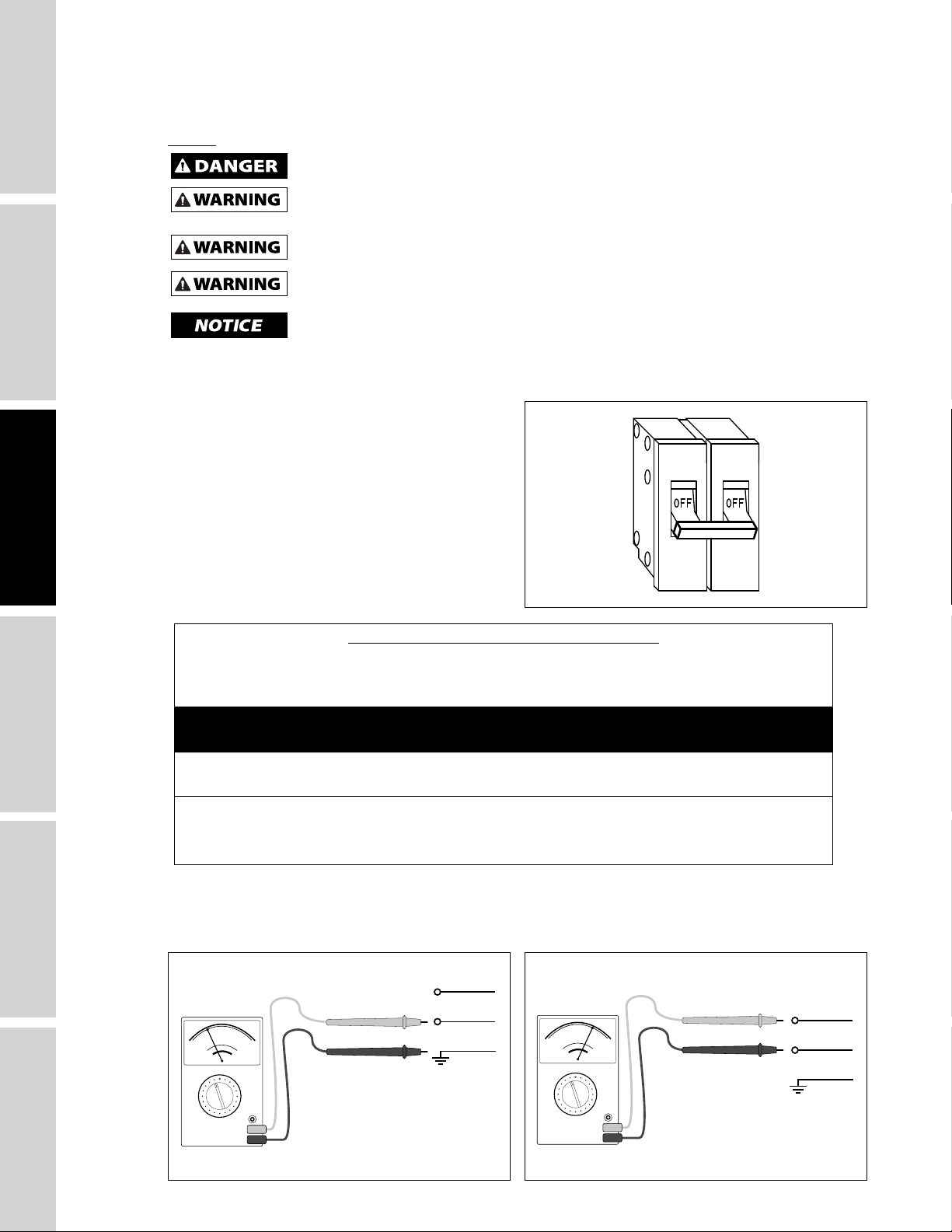
1. Inspect the source wiring before continuing with installation. Confirm voltage with volt meter line-toground (see Figure 7).
Volt Meter -
120 Volts
Figure 7 Figure 8
Line Wire
Line Wire
Ground Wire
Volt Meter -
230/240 Volts
Line Wire
Line Wire
Ground Wire
10
Page 13
Volt meter should read 120 Volts.
Confirm voltage with volt meter line-to-line Volt
meter should read 230 / 240 Volts (see Figure 8).
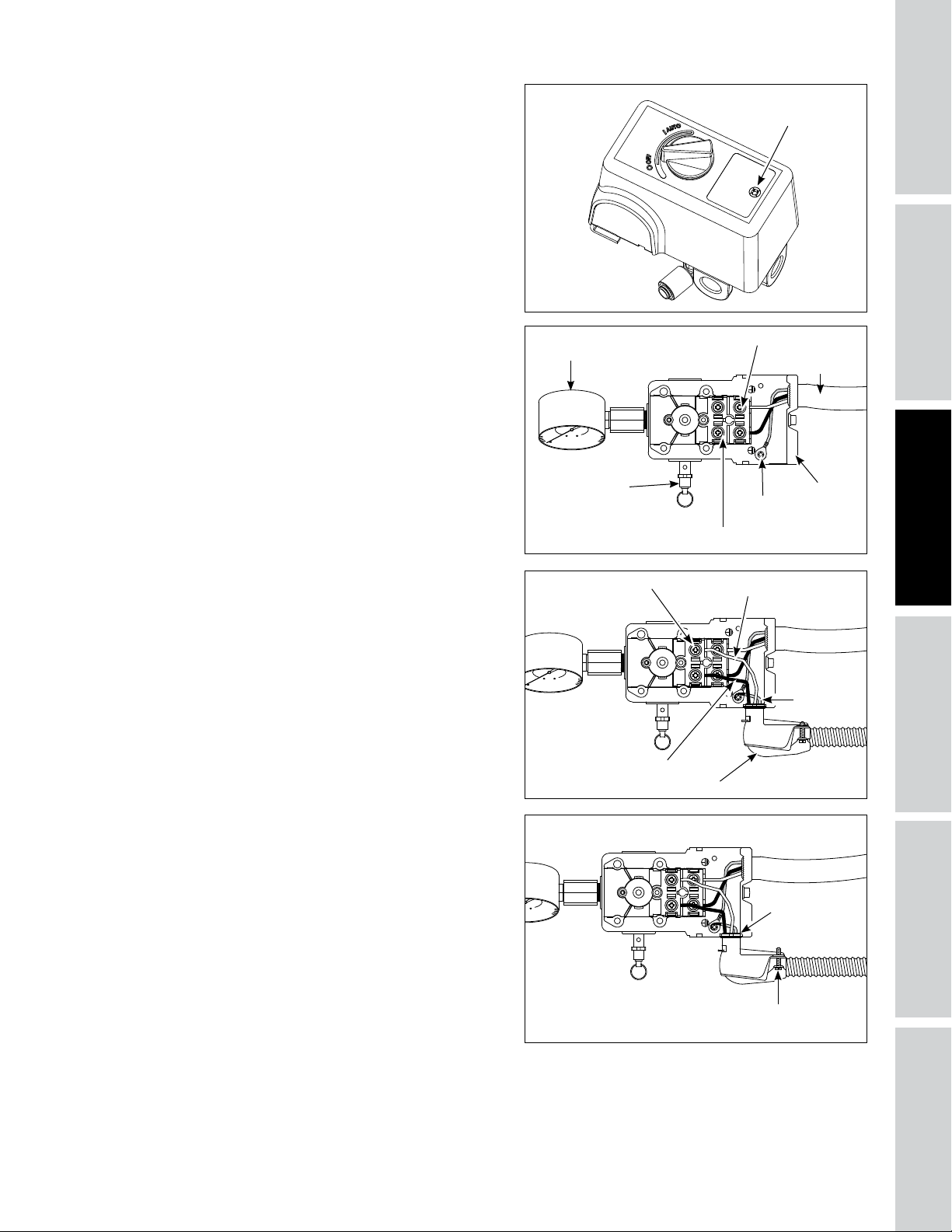
2. Remove the pressure switch cover by loosening
the screw (see Figure 9). Use a Phillips
screwdriver (not included). Pressure switch styles
may vary.
Screw
SPECIFICATIONS
SAFETY /
Figure 9
3. Familiarize yourself with the pressure switch
once cover is removed.
4. Remove ground screw. Install strain relief on
pressure switch. DO NOT tighten strain relief on
power cord until wiring is complete. Insert the
bare wires (black, white, bare/green) through
the strain relief.
Attach bare/green ground wire first to ground
screw on pressure switch body.
Look for the “Line” markings on pressure
switch. Install Line wires and tighten terminal
screws.
Tank Pressure
Gauge
ASME Safety
Valve
Figure 10
Terminal Screw
Black Line Wire
Figure 11
Line Terminal
Power Cord
Strain Relief
Motor Terminal
Motor Power
Ground
Screw
White Line Wire
Cord
Motor Cord
Strain Relief
Bare/Green
Ground
Wire
INSTALLATION
ASSEMBLY /
5. Tighten strain relief nut. Place a flathead
screwdriver (not included) into raised notch and
tap screwdriver with hammer (not included)
until tight.
Tighten strain relief screws to hold power cord
securely. Replace the pressure switch cover
(knob must be in the same position as when
removed to sit correctly in place). Tighten the
pressure switch screw with Phillips screwdriver.
Check that switch is in the OFF position. Follow
break-in procedure starting on page 13.
11
Figure 12
Strain Relief
Nut
Strain Relief Screw
TROUBLESHOOTINGOPERATION
MAINTENANCE /
REPAIR
Page 14
SAFETY /
INSTALLATION INSTRUCTIONS (CONTINUED)
Grounding
GETTING STARTED
SPECIFICATIONS
Improperly grounded electrical components are shock hazards. Make sure all the
This product must be grounded. Grounding reduces the risk of electrical shock by providing an escape wire
for the electric current if short circuit occurs. This product must be installed and operated with a power cord
or cable that has a grounding wire.
Install permanent wiring from the electrical source
to the pressure switch with a ground conductor
connected to the grounding screw on the pressure
switch. A properly sized cord with a ground conductor
and plug may also be installed by the user.
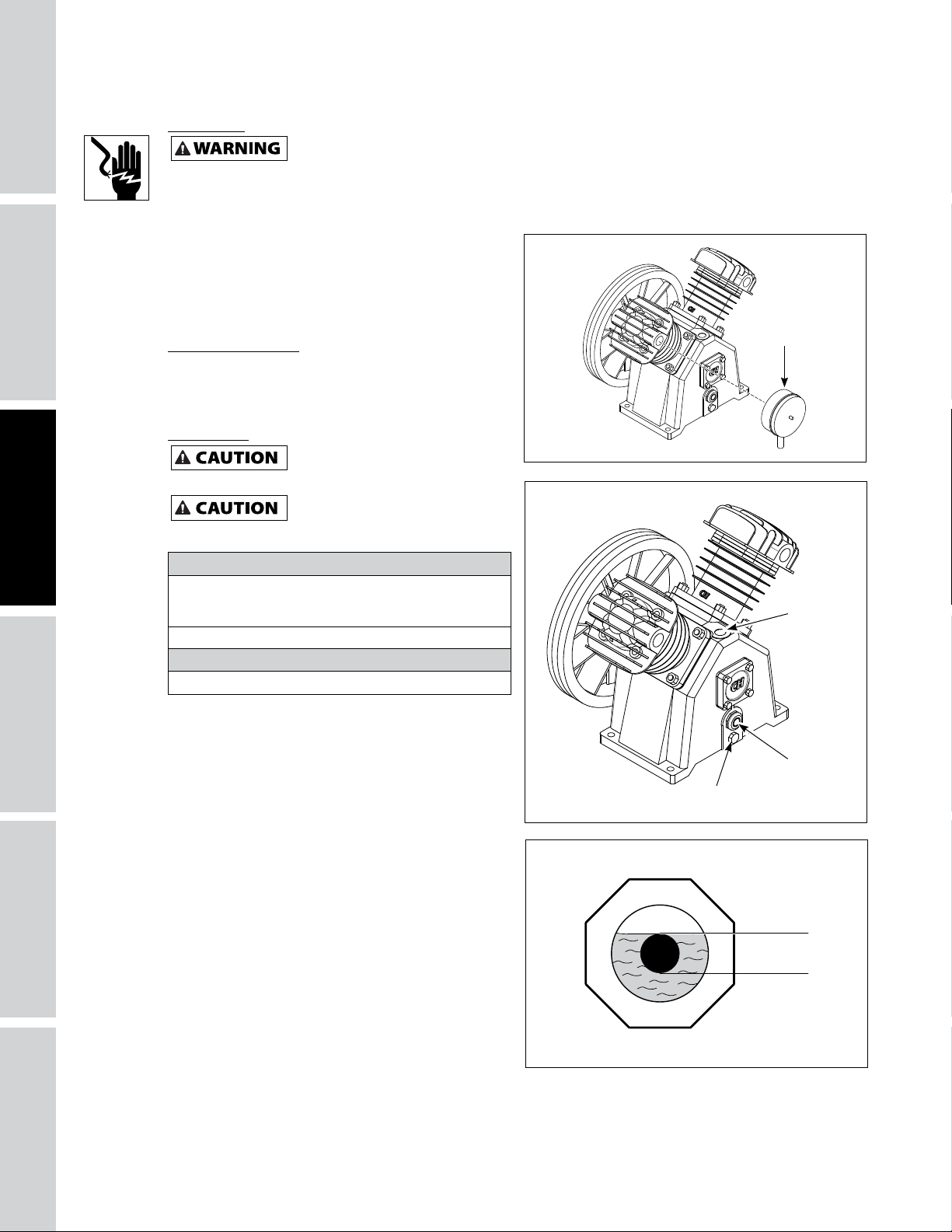
Installing Air Filter
Install air filter on pump (see Figure 13). Filter styles
may vary.
components are properly grounded to prevent death or serious injury.
Air Filter
ASSEMBLY /
INSTALLATION
Lubrication
This unit contains no oil.
the center of the sight gauge (see Figure 15).
Using any other type of oil may
valves.
Recommended Oil (2 Options)
Single viscosity SAE 30 ISO100 nondetergent compressor
oil. Part number ST125303AV (0.5 qt) or ST126701AV (4
qt).
10W30 synthetic oil such as Mobil 1® or CE0032 (1 qt).
Oil Capacity
Approximately 47.4 oz.
Remove oil fill plug on pump. Check oil level; some
models are shipped with oil in the pump. Add oil if
needed. Fill the pump with oil to the center of the
sight gauge using oil fill opening (see Figure 15).
Place oil fill plug back on pump.
through the breather cap opening as this may cause oil to
leak and spray out during operation.
Do not use regular automotive oil. Additives in
regular motor oil can cause valve deposits and
reduce pump life.
For maximum pump life, drain and replace oil after
the first 50 hours of run time and then follow the
regular maintenance schedule outlined later in the
manual.
This pump has an oil sight glass as shown in Figure
14. Oil level can be monitored and maintained as
shown in Figure 15.
NOTE: Some residual oil may still be in the pump
from factory testing leaving a thin coat on the sight
gauge; however, there is not enough oil to operate
the unit.
Before operating compressor, fill to
shorten pump life and damage
Do NOT fill the pump
Figure 13
Oil FIll
Plug
Sight
Glass
Oil Drain Plug
Figure 14
Full
Low
Sight Glass
Figure 15
12
Page 15
OPERATING INSTRUCTIONS
Start-up / Break-in Procedure
Do not attach air tools to open end of the hose until start-up is completed and the unit checks
okay.
1. Return power to unit from main.
2. Check oil level per the Lubrication Section of this manual.
3. Open the tank drain valve (see Figure 16). Turn outlet valve to open air flow.
4. Move pressure switch to the AUTO position to run the unit (see Figure 17).
5. Run the unit for thirty (30) minutes at zero (0) PSI (under no load) to break in pump parts.
6. Move the pressure switch lever or knob to OFF and turn tank drain valve to shut off air flow. The
compressor is now ready for use.
7. Change oil after first fifty (50) hours of operation. Perform oil changes every three (3) months or two
hundred (200) hours of run time, whichever comes first.
Never disconnect threaded joints with pressure in tank!
SPECIFICATIONS
SAFETY /
INSTALLATION
ASSEMBLY /
Tank Drain
Figure 16 Figure 17
Valve
On/Off Cycling of Compressor
Drain tank every day to prevent corrosion and possible injury due to tank damage. For optimal
drain with more than 40 PSI in tank or drain valve may be damaged. Drain tank of moisture daily using the drain valve
in the bottom of the tank.
In the AUTO position, the compressor pumps air into the tank. When a shut-off (preset “cut-out”) pressure
is reached, the compressor automatically shuts off.
If the compressor is left in the AUTO position and air is depleted from the tank by use of a tire chuck, tool,
etc., the compressor will restart automatically at its preset “cut-in” pressure. When a tool is being used
continuously, the compressor will cycle on and off automatically.
In the OFF position, the compressor will not operate.
MOISTURE IN COMPRESSED AIR
Moisture in compressed air will form into droplets as it comes from an air compressor pump. When
humidity is high or when a compressor is in continuous use for an extended period of time, this
moisture will collect in the tank. When using a paint spray or sandblast gun, this water will be carried
from the tank through the hose, and out of the gun as droplets mixed with the spray material.
IMPORTANT: This condensation will cause water spots in a paint job, especially when spraying other
than water based paints. If sandblasting, it will cause the sand to cake and clog the gun, rendering
it ineffective. A filter in the air line, located as near to the gun as possible, will help eliminate this
moisture.
performance of tank drain, tank pressure should be between 10 PSI - 40 PSI. Do not operate
Drain liquid from tank daily.
TROUBLESHOOTINGOPERATION
MAINTENANCE /
REPAIR
13
Page 16
SAFETY /
ASSEMBLY /
TROUBLESHOOTING GUIDE
SYMPTOM POSSIBLE CAUSE(S) CORRECTIVE ACTION
Low discharge pressure 1. Air demand exceeds pump capacity 1. Reduce air demand or use a compressor with more
GETTING STARTED
SPECIFICATIONS
Excessive noise (knocking)
INSTALLATION
Large quantity of oil in the
discharge air
NOTE: In an oil lubricated
compressor there will always
be a small amount of oil in the
air stream.
Water in discharge air/tank Normal operation. The amount of water
capacity.
2. Air leaks (fittings, tubing on
compressor, or plumbing outside of
system).
3. Restricted air intake 3. Clean or replace the air filter element.
4. Blown gaskets 4. Replace any gaskets proven faulty on inspection.
5. Leaking or damaged valves 5. Remove head and inspect for valve breakage,
1. Loose motor pulley or flywheel. 1. Tighten pulley / flywheel clamp bolts and set-
2. Loose fasteners on pump or motor. 2. Tighten fasteners.
3. Lack of oil in crankcase 3. Check for proper oil level; if low, check for possible
4. Worn connecting rod 4. Replace connecting rod. Maintain oil level and
5. Worn piston pin bores 5. Remove piston assemblies from the compressor and
6. Piston hitting the valve plate 6. Remove the compressor head and valve plate
7. Noisy check valve in compressor
system
1. Worn piston rings 1. Replace with new rings. Maintain oil level and
2. Compressor air intake restricted
3. Excessive oil in compressor
4. Wrong oil viscosity
increases with humid weather
2. Listen for escaping air. Apply soap solution to
all fittings and connections. Bubbles will appear
at points of leakage. Tighten or replace leaking
fittings or connections. Use pipe thread sealant.
misaligned valves, damaged valve seats, etc. Replace
defective parts and reassemble.
Install a new head gasket
screws.
damage to bearings. Dirty oil can cause excessive
wear.
change oil more frequently.
inspect for excess wear. Replace excessively worn
piston pin or pistons, as required. Maintain oil level
and change oil more frequently.
and inspect for carbon deposits or other foreign
matter on top of piston. Replace head and valve
plate using new gasket. See Lubrication section for
recommended oil.
7. Replace check valve.
Do not disassemble check valve
change oil more frequently.
2. Clean or replace filter. Check for other restrictions
in the intake system.
3. Drain down to full level.
4. Use Mobil 1
1. Drain tank more often. At least daily.
2. Add a filter to reduce the amount of water in the
air line.
each time the head is removed.
with air pressure in tank.
®
10W-30 or full synthetic.
14
Page 17
TROUBLESHOOTING GUIDE
SYMPTOM POSSIBLE CAUSE(S) CORRECTIVE ACTION
Motor hums and runs slowly or
not at all.
Reset mechanism cuts out
repeatedly or circuit breaker
trips repeatedly.
Tank does not hold pressure
when compressor is off and
the shut off valve is closed.
Pressure switch continuously
blows air out the unloader
valve
Pressure switch does not
release air when the unit shuts
off
Excessive vibration
1. Low voltage. 1. Check incoming voltage. It should be approximately
2. Too many devices on same circuit. 2. Limit the circuit to the use of compressor only.
3. Loose electrical connections. 3. Check all electrical connections.
4. Malfunctioning pressure switch contacts will not close.
5. Malfunctioning check valve. 5. Replace check valve.
6. Defective unloader valve on pressure
switch.
7. Defective motor capacitor(s). 7. Replace capacitor(s).
8. Defective motor. 8. Replace motor.
1. Lack of proper
ventilation / room temperature too
high.
2. Too many devices on same circuit. 2. Limit the circuit to the use of only the air
3. Restricted air intake. 3. Clean or replace filter element.
4. Loose electrical connection. 4. Check all electrical connections.
5. Pressure switch shut-off pressure set
too high.
6. Malfunctioning check valve. 6. Replace check valve.
7. Defective unloader valve on pressure
switch.
8. Defective motor capacitor(s). 8. Replace capacitor(s).
9. Malfunctioning motor. 9. Replace motor.
1. Air leaks (fittings, tubing on
compressor, or plumbing outside
system).
2. Worn check valve. 2. Replace check valve.
3. Check tank for cracks or pin holes. 3. Replace tank. Never repair a damaged tank.
Malfunctioning check valve Replace the check valve if the unloader valve on the
Malfunctioning unloader valve on
pressure switch
1. Loose fasteners on pump or motor 1. Tighten fasteners.
2. Belt needs replaced 2. Replace with correct size.
3. Belt alignment 3. Align flywheel and pulley.
230 volts. Motor will not run properly on 208 volts.
Low voltage could be due to wires (from electrical
source to compressor) being too small in diameter
and / or too long. Have a qualified electrician check
these conditions and make repairs as needed.
4. Replace pressure switch.
Do not disassemble check valve
6. Replace unloader valve.
1. Move compressor to well-ventilated area.
compressor.
5. Replace pressure switch.
Do not disassemble check valve
7. Replace unloader valve.
1. Check all connections with soap and water solution.
Tighten; or remove and apply sealant to threads,
then reassemble.
Do not disassemble check valve
pressure switch bleeds off constantly when unit shuts
off.
Do not disassemble check valve
Replace the pressure switch if it does not release the
pressure for a short period of time when the unit shuts
off.
Do not disassemble pressure
with air pressure in tank.
with air pressure in tank.
with air pressure in tank.
with air pressure in tank.
switch with air pressure in tank
SPECIFICATIONS
SAFETY /
INSTALLATION
ASSEMBLY /
TROUBLESHOOTINGOPERATION
MAINTENANCE /
REPAIR
15
Page 18
MAINTENANCE AND INSPECTION INSTRUCTIONS
SAFETY /
ASSEMBLY /
GETTING STARTED
SPECIFICATIONS
INSTALLATION
Disconnect, tag and lock out power source then release all pressure from the system before
attempting to install, service, relocate or perform any maintenance.
All repairs should be performed by an authorized service representative.
In order to maintain efficient operation of the compressor system,
check the air filter and oil level before each use. The ASME safety
valve should also be checked daily (see Figure 18). Pull ring on
safety valve and allow the ring to snap back to normal position.
This valve automatically releases air if the tank pressure exceeds
the preset maximum. If air leaks after the ring has been released,
or the valve is stuck and cannot be actuated by the ring, the ASME
safety valve must be replaced.
Do not tamper with the ASME safety valve.
Figure 18 - ASME Safety Valve
Tank
Never attempt to repair or modify a tank! Welding, drilling or any other modification will
or damaged tanks.
Drain Tank: Disconnect, tag and lock out power source; release pressure. Drain moisture from tank by
opening drain valve underneath tank once tank pressure is less than 40 PSI (See Figure 16 on page 13).
The tank should be carefully inspected at a minimum of once a year. Look for cracks forming near the
welds. If a crack is detected, remove pressure from tank immediately and replace.
weaken the tank resulting in damage from rupture or explosion. Always replace worn, cracked
Drain liquid from tank daily.
Compressor Lubrication
See Installation. Add oil as required. The oil should be changed every three months or after every 200 hours
of operation; whichever comes first.
If the compressor is run under humid conditions for short periods of time, the humidity will condense in
the crankcase and cause the oil to look creamy. Oil contaminated by condensed water will not provide
adequate lubrication and must be changed immediately. Using contaminated oil will damage bearings,
pistons, cylinders and rings and is not covered under warranty. To avoid water condensation in the oil,
periodically run the compressor with tank pressure near 120 PSI for 2-stage compressors by opening the
drain cock or an air valve connected to the tank or hose. Run the pump for an hour at a time at least once a
week or more often if the condensation reoccurs.
IMPORTANT: Change oil after first 50 hours of operation.
Air Filter
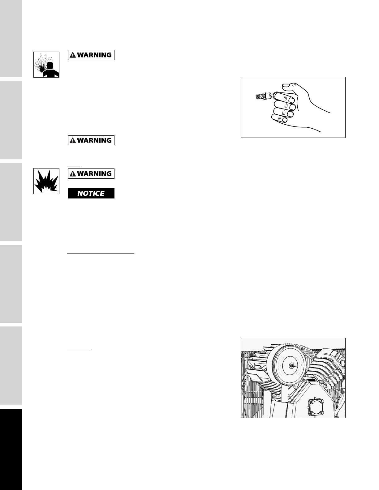
Never run the compressor pump without an intake air filter or
with a clogged intake air filter. The air filter element should be
checked monthly (see Figure 19). Operating compressor with
a dirty filter can cause high oil consumption and increase oil
contamination in the discharge air. If the air filter is dirty it must
be replaced.
Figure 19
16
Page 19
Belts
Lock out and tag the power then release all pressure from the tank to prevent unexpected
Check belt tension every 3 months. Adjust belt tension to allow 3/8 inch to 1/2 inch deflection with normal
thumb pressure. Also, align belts using a straight edge against the face of the flywheel and touching the
rim on both sides of the face. The belts should be parallel to this straight edge (see Figure 20). Dimension A
should be the same as B and C to ensure proper alignment of the belts.
Slots in the bed-plate allow for sliding the motor back and forth to adjust belt tension.
movement of the unit.
Motor
Motor
Drive
Pulley
A B
Air Compressor
Flywheel
Straight Edge
C
Setscrew
Figure 20 - Top View
SPECIFICATIONS
SAFETY /
INSTALLATION
ASSEMBLY /
Removing Belt Guard
When removing belt guard front to
inspect or replace belts, inspect plastic retaining
clips and replace if damaged or if clip can be removed without a tool.
1
Removing Retaining Clips
1. Using crescent wrench on pliers, rotate clip 90°.
2. Pull clip out and away from beltguard.
3. Reverse process to reinstall after inspecting the clip.
Figure 21
2
Storage
If compressor is to be stored for a short period of time, make sure that it is stored in a normal position and
in a cool protected area.
MAINTENANCE SCHEDULE
OPERATION DAILY WEEKLY MONTHLY 3 MONTHS
Check Oil Level
Drain Tank
Check Air Filter
Check Safety Valve
Clean Unit
Check Belt Tightness
Change Oil*
* Change oil after first fifty (50) hours of operation then perform oil changes every three (3) months or two hundred
(200) hours of run time, whichever comes first.
l
l
l
l
l
l
l
TROUBLESHOOTINGOPERATION
MAINTENANCE /
REPAIR
17
Page 20

SAFETY /
ASSEMBLY /
REPAIR PARTS ILLUSTRATION FOR CE5002 AND XC602100
GETTING STARTED
2
SPECIFICATIONS
INSTALLATION
3
4
For Repair Parts, visit www.campbellhausfeld.com
24 hours a day – 365 days a year
Please provide following information:
- Model number
- Serial number (if any)
- Part description and number as shown in parts list
1
18
Page 21

REPAIR PARTS LIST FOR CE5002 AND XC602100
Ref.
No. Description Part Number: Qty.
1
2
3
4
60 Gallon Tank AR068400CG 1
5HP 2-Stage Reciprocating Pump XC002500IP 1
3.5HP Electric Motor MC019700IP 1
Pressure Switch CW220000AV 1
UNIT SERVICE PARTS
Ref.
No. Description Part Number: Qty.
Drain Valve SR060513SV 1
Motor Pulley PU017300AV 1
Vee Belt BT021501AV 1
Check Valve/Exhaust Tube Kit XC000800SV 1
Pressure Switch Kit MY001000SV 1
Belt Guard Kit BG900100SV 1
PUMP SERVICE PARTS
Ref.
No. Description Part Number: Qty.
Valve Replacement Kit XC001000AV 1
Ring Replacement Kit XC001100AV 1
Gasket Kit XC001300AV 1
Flywheel XC001400AV 1
Pump Accessories XC001500AV 1
Air Filter Element XC001700AV 1
SPECIFICATIONS
SAFETY /
INSTALLATION
ASSEMBLY /
19
TROUBLESHOOTINGOPERATION
MAINTENANCE /
REPAIR
Page 22

Reminder: Keep your dated proof of purchase for warranty purposes! Attach it to this manual or file it for safekeeping.
LIMITED WARRANTY
1. DURATION: From the date of purchase by the original purchaser as follows: Three Years.
2. WHO GIVES THIS WARRANTY: Campbell Hausfeld a Marmon/Berkshire Hathaway Company, 100 Production Drive, Harrison,
Ohio, 45030. Visit www.campbellhausfeld.com.
3. WHO RECEIVES THIS WARRANTY (PURCHASER): The original purchaser (other than for purposes of resale) of the
compressor.
4. WHAT PRODUCTS ARE COVERED BY THIS WARRANTY: This air compressor.
5. WHAT IS COVERED UNDER THIS WARRANTY: Parts and Labor to remedy substantial defects due to material and
workmanship during the first year of ownership with the exceptions noted below. Parts only to remedy substantial defects
due to material and workmanship during remaining term of coverage with exceptions noted below.
6. WHAT IS NOT COVERED UNDER THIS WARRANTY:
A. Implied warranties, including those of merchantability and FITNESS FOR A PARTICULAR PURPOSE ARE LIMITED FROM
THE DATE OF ORIGINAL PURCHASE AS STATED IN THE DURATION. Some States do not allow limitations on how long an
implied warranty lasts, so the above limitations may not apply to you
B. ANY INCIDENTAL, INDIRECT, OR CONSEQUENTIAL LOSS, DAMAGE, OR EXPENSE THAT MAY RESULT FROM ANY DEFECT,
FAILURE, OR MALFUNCTION OF THE CAMPBELL HAUSFELD PRODUCT. Some States do not allow the exclusion or
limitations of incidental or consequential damages, so the above limitation or exclusion may not apply to you.
C. Any failure that results from an accident, purchaser’s abuse, neglect or failure to operate products in accordance with
instructions provided in the owner’s manual(s) supplied with compressor.
D. Pre-delivery service, e.g. assembly, oil or lubricants, and adjustment.
E. Items or service that is normally required to maintain the product, i.e. lubricants, filters and gaskets, etc.
F. Additional items not covered under this warranty:
1. Excluded items pertaining to All Compressors
a. Any component damaged in shipment or any failure caused by installing or operating unit under conditions not
in accordance with installation and operation guidelines or damaged by contact with tools or surroundings.
b. Pump or valve failure caused by rain, excessive humidity, corrosive environments or other contaminants.
c. Cosmetic defects that do not interfere with compressor functionality.
d. Rusted tanks, including but not limited to rust due to improper drainage or corrosive environments.
e. The following components are considered normal wear items and are not covered after the first year of
ownership. Electric motor, check valve, pressure switch, regulator, pressure gauges, hose, tubing, pipe, fittings
and couplers, screws, nuts, hardware items, belts, pulleys, flywheel, air filter and housing, gaskets, seals, oil
leaks, air leaks, oil consumption or usage, piston rings.
f. Tank drain valves.
g. Damage due to incorrect voltage or improper wiring.
h. Other items not listed but considered general wear parts.
i. Pressure switches, air governors, load/unload devices, throttle control devices and safety valves modified from
factory settings.
j. Damage from inadequate filter maintenance.
k. Induction motors operated with electricity produced by a generator.
2. Excluded items specific to Lubricated Compressors:
a. Pump wear or valve damage caused by using oil not specified.
b. Pump wear or damage caused by any oil contamination.
c. Pump wear or damage caused by failure to follow proper oil maintenance guidelines, operation below proper
oil level or operation without oil.
G. Labor, service call, or transportation charges after the first year of ownership of stationary compressors. Stationary
compressors are defined as not including a handle or wheels.
7. RESPONSIBILITIES OF WARRANTOR UNDER THIS WARRANTY: Repair or replace, at Warrantor’s option, compressor or
component which is defective, has malfunctioned and/or failed to conform within the duration of the specific warranty
period.
8. RESPONSIBILITIES OF PURCHASER UNDER THIS WARRANTY:
A. Provide dated proof of purchase and maintenance records.
B. Visit www.campbellhausfeld.com to obtain your warranty service options. Freight costs must be borne by the purchaser.
C. Use reasonable care in the operation and maintenance of the products as described in the owner’s manual(s).
D. Repairs requiring overtime, weekend rates, or anything beyond the standard manufacturer warranty repair labor
reimbursement rate.
E. Time required for any security checks, safety training, or similar for service personnel to gain access to facility.
F. Location of unit must have adequate clearance for service personnel to perform repairs and be easily accessible.
9. WHEN WARRANTOR WILL PERFORM REPAIR OR REPLACEMENT UNDER THIS WARRANTY: Repair or replacement will be
scheduled and serviced according to the normal work flow at the servicing location, and depending on the availability of
replacement parts.
This Limited Warranty applies in the U.S., Canada and Mexico only and gives you specific legal rights. You may also have other
rights which vary from state to state or country to country.
20
Page 23

Compresseur d’air électrique
Instructions d’Utilisation et Manual de Pièces
© 2018 Campbell Hausfeld
A Marmon/Berkshire Hathaway Company
Modèles: CE5002 et XC602100
FR
IN573900 10/18
Page 24

Lire et conserver ces instructions. Il faut les lire attentivement avant de
commencer à assembler, installer, faire fonctionner ou entretenir l’appareil décrit.
Pour se protéger et protéger autrui, observer toutes les informations sur la
sécurité. Négliger d’appliquer ces instructions peut causer
des blessures et/ou des dommages matériels! Conserver ces instructions pour
consultation ultérieure.
RAPPEL: Conservez votre preuve d’achat datée aux fins de garantie! Attachez-le à
ce manuel ou classez-le pour le garder en sécurité.
Pour de l’information sur les pièces,
produits et services veuillez visiter
N° de modèle : _____________________
N° de série : _______________________
Date d’achat : _____________________
ENREGISTREZ VOTRE PRODUIT EN LIGNE MAINTENANT ! www.campbellhausfeld.com/reg
LIRE ET SUIVRE TOUTES LES INSTRUCTIONS • CONSERVER CES INSTRUCTIONS • NE PAS JETER
www.campbellhausfeld.com
Campbell Hausfeld
100 Production Drive
Harrison, Ohio 45030
Page 25

AVANT DE COMMENCER
Description
Les unités de compresseur d’air ont été conçues pour fournir de l’air comprimé aux outils électriques
pneumatiques, faire fonctionner les pistolets de pulvérisation et approvisionner en air les soupapes et
actionneurs pneumatiques. Les pompes alimentées par ces unités comportent des roulements lubrifiés à
l’huile. Un faible contenu en huile est présent dans le flux d’air comprimé. Les applications nécessitant de
l’air sans vapeurs d’huile devraient disposer de filtres adéquats déjà installés. Les unités de compresseur
d’air doivent être installées selon les instructions fournies sur un plancher solide. Toute autre utilisation de
ces unités annulera la garantie et le fabricant ne sera pas tenu responsable des problèmes ou dommages
résultant de cette mauvaise utilisation.
RÉFÉRENCE RAPIDE
Huile recommandée (2 Options)
Huile de compresseur non détergente SAE 30 ISO100 à viscosité unique. Numéro de pièce
ST125303AV (0,47 L) ou ST126701AV (3,79 L).
Huile synthétique 10W30 telle que Mobil 1® ou CE0032 (0,95 L).
Capacité D’Huile
Environ 1.4 L
DÉBALLAGE
Ne pas soulever ni déplacer le modèle sans équipement convenable et s’assurer que le modèle
refroidisseurs. Ne pas utiliser le modèle pour soulever d’autre équipement qui est attaché au compresseur.
Dès que l’appareil est déballé, l’inspecter attentivement pour tout signe de dommages en transit. Vérifier
s’il y a des pièces desserrées, manquantes ou endommagées. Vérifier pour s’assurer que tous les accessoires
fournis sont inclus avec l’appareil. Pour toutes questions, pièces endommagées ou manquantes, veuillez
visiter www.campbellhausfeld.com pour l’assistance à la clientèle.
Ne pas utiliser un modèle qui a été endommagé pendant le transport, la manipulation ou
matériels.
Articles requis - non inclus
• Huile
• Ancres en béton
• Blocs d’isolation
• Vanne d’isolement
• Cordon d’alimentation / disjoncteur électrique
soit bien fixé à l’appareil de levage. Ne pas soulever le modèle avec les tuyaux ou les
l’utilisation. Le dommage peut résulter en explosion et peut causer des blessures ou dégâts
CARACTÉRISTIQUES
SÉCURITÉ /
ASSEMBLAGE /
INSTALLATION
UTILISATION
Fr1
DÉPANNAGE
ENTRETIEN /
RÉPARATION
Page 26

INSTRUCTIONS GÉNÉRALES DE SÉCURITÉ
DÉMARRAGE
DE L’APPAREIL
SÉCURITÉ /
CARACTÉRISTIQUES
Directives De Sécurité
Ce manuel contient de l’information très importante qui est fournie pour la SÉCURITÉ et pour ÉVITER LES
PROBLÈMES D’ÉQUIPEMENT. Rechercher les symboles suivants pour cette information.
Danger indique une situation dangereuse imminente qui MÈNERA à la mort ou à des blessures
graves si elle n’est pas évitée.
Avertissement indique une situation potentiellement dangereuse qui, si elle n’est pas évitée,
POURRAIT mener à la mort ou à de graves blessures.
Attention indique une situation potentiellement dangereuse qui, si elle n’est pas évitée, PEUT
mener à des blessures mineures ou modérées.
Avis indique de l’information importante qui pourrait endommager l’équipement si elle n’est
pas respectée.
IMPORTANT ou REMARQUE: Information qui exige une attention spéciale.
Symboles De Sécurité
Les symboles de sécurité suivants apparaissent dans l’ensemble de ce manuel pour vous aviser des dangers
et précautions importants de sécurité.
MANUAL
INSTALLATION
ASSEMBLAGE /
UTILISATION
DÉPANNAGE
Porter une
protection oculaire
et un masque
Risques de
fumées
Lire le manuel
d’abord
Risque de
pression
Trop lourd du
haut
Risque de
choc
Risque
d’incendie
Risque de
pièces mobiles
Risque
de pièces
chaudes
Risque
d’explosion
Proposition 65 de Californie
Ce produit peut vous exposer à des produits chimiques incluant le plomb, connus par l’état de
la Californie comme pouvant causer le cancer, des anomalies congénitales ou d’autres troubles
de la reproduction. Pour plus d’informations, rendez-vous sur le site www.P65Warnings.ca.gov.
Vous pouvez créer de la poussière en coupant, ponçant, perçant ou meulant les matériaux tels
contient souvent des produits chimiques reconnus pour causer le cancer, les déformations congénitales.
que le bois, la peinture, le métal, le béton, le ciment ou autre maçonnerie. Cette poussière
Illinois Lead Poisoning Prevention Act (Loi sur la prévention de l’empoisonnement au plomb de
l’État de l’Illinois)
CONTIENT DU PLOMB. PEUT ÊTRE NOCIF SI INGÉRÉ OU MÂCHÉ. RESPECTE LES NORMES
FÉDÉRALES.
Fr2
Page 27

Importantes Instructions de Sécurité
S’il vous plaît lire et conserver ces instructions. Lire attentivement avant de monter, installer, utiliser ou de procéder à
l’entretien du produit décrit. Se protéger ainsi que les autres en observant toutes les instructions de sécurité, sinon, il y a
risque de blessure et/ou dégâts matériels! Conserver ces instructions comme référence.
Ce manuel contient des informations concernant la sécurité, le fonctionnement et l’entretien. Si vous avez
des questions, veuillez visiter www.campbellhausfeld.com pour l’assistance à la clientèle.
MANUAL
AVERTISSEMENT D’AIR RESPIRABLE
Ce compresseur/pompe n’est pas équipé pour et ne devrait pas être utilisé “comme soi” pour fournir de
l’air respirable. Pour les applications d’air pour la consommation humaine, il est nécessaire d’équiper le
compresseur d’air/pompe avec de l’équipement de sécurité en canalisation et d’alarme. Cet équipement
additionnel est nécessaire pour filtrer et purifier l’air afin d’atteindre les spécifications minimales pour
la respiration Grade D décrite dans le Compressed Gas Association Commodity Specification G 7.1,
OSHA 29 CFR 1910. 134, and/or Canadian Standards Associations (CSA).
DÉNÉGATION DES GARANTIES
Si le compresseur est utilisé pour les applications d’air respirable et l’équipement de sécurité en
canalisation et d’alarme n’est pas utilisé simultanément, les garanties en existance seront annulées, et
Campbell Hausfeld dénie toute responsabilité pour n’importe quelle perte, blessure ou dommage.
Généralités sur la Sécurité
Puisque le compresseur d’air et les autres composants (article pompe, pistolet de pulvérisation, filtres,
lubrifiants, tuyaux, etc.) utilisés font partie d’un système de pompage à haute pression, les précautions de
sécurité suivantes doivent être prises en considération à tout moment :
• Lire attentivement tous manuels compris avec ce produit. Bien se familiariser avec les commandes et
l’utilisation correcte de l’équipement.
• Suivre tous les codes d’électricité et de sécurité locaux ainsi que: National Electrical Codes (NEC) et
Occupational Safety and Health Act (OSHA) des É.-U.
• Seules les personnes bien familiarisées avec ces règles d’utilisation doivent être autorisées à se servir du
compresseur.
• Garder les visiteurs à l’écart de/et NE JAMAIS permettre les enfants dans l’endroit de travail.
• Utiliser des lunettes de sécurité et la protection auditive pendant l’utilisation du modèle.
• Ne pas se tenir debout sur/ou utiliser le modèle comme une prise.
• Inspecter le système d’air comprimé et pièces détachées électriques pour toute indication de dommage,
détérioration, faiblesse ou fuites avant chaque utilisation. Réparer ou remplacer toutes pièces
défectueuses avant l’utilisation.
• Inspecter le degré de serrage de toutes attaches par intervalles régulières.
Cecompresseur est extrêmement lourd. L’appareil doit être fixé au plancher à l’aide de boulons
et de coussinets isolants avant utilisation afin d’éviter de l’endommager, ouencore de causer
des blessures ou la mort.
CARACTÉRISTIQUES
SÉCURITÉ /
ASSEMBLAGE /
INSTALLATION
UTILISATION
DÉPANNAGE
N’installez jamais de vanne d’arrêt entre le compresseur et le réservoir.
Les moteurs, l’équipement et les commandes électriques peuvent causer des arcs électriques
modèle près d’un gaz ou d’une vapeur inflammable. Ne jamais entreposer les liquides ou gaz inflammables près du
compresseur.
Ne jamais utiliser un compresseur sans carter de courroie. Ce modèle peut se démarrer sans
matériels.
qui peuvent allumer un gaz ou une vapeur inflammable. Ne jamais utiliser ou réparer le
avis. Le contact avec les pièces mobiles peut causer des blessures personnelles ou dégâts
• Ne pas porter les vêtements flottants ni la bijouterie qui peuvent se prendre dans les pièces mobiles du
modèle.
Les pièces du compresseur peuvent être chaudes même si le modèle n’est pas en
marche.
Fr3
ENTRETIEN /
RÉPARATION
Page 28

INSTRUCTIONS GÉNÉRALES DE SÉCURITÉ (SUITE)
DÉMARRAGE
DE L’APPAREIL
SÉCURITÉ /
CARACTÉRISTIQUES
• Garder les doigts à l’écart d’un compresseur qui est en marche; les pièces mobiles et chaudes peuvent
causer des blessures et/ou brûlures.
• Si le compresseur vibre anormalement, ARRÊTER le moteur et l’inspecter immédiatement. La vibration
est généralement une indication d’un problème.
• Pour réduire le risque d’incendie, garder l’extérieur du moteur libre d’huile, de solvant ou de graisse
excessive.
Une soupape de sûreté ASME avec une classification qui ne dépasse pas 1 379 kPa doit être
et une classification de pression suffisants pour protéger les pièces pressurisées contre l’éclatement.
La pression de fonctionnement maximale est de 1 207 kPa pour les compresseurs
une valeur supérieure à 1 207 kPa (2 étages.
installée dans le réservoir de ce compresseur. La soupape de sûreté ASME doit avoir un débit d’air
Voir les spécifications du compresseur pour une pression de fonctionnement maximale. Ne pas faire
fonctionner avec un manostat ou soupapes pilotes réglés au delà de la pression de fonctionnement
maximum.
monophasés. Ne pas faire fonctionner avec un manostat ou des vannes pilotes configurés sur
• Ne jamais essayer d’ajuster la soupape de sûreté ASME. Garder la soupape de sûreté libre de peinture et
autres accumulations.
Ne jamais utiliser les tuyaux plastiques (CPV) pour l’air comprimé. Ceci peut
Ne jamais essayer de réparer ni de modifier un réservoir! Le soudage, le perçage ou autre
d’explosion. Toujours remplacer un réservoir usé, fendu ou endommagé.
causer des blessures graves ou la mort.
modifications peuvent affaiblir le réservoir et peut résulter en dommage de rupture ou
Purger le liquide du réservoir quotidiennement.
INSTALLATION
ASSEMBLAGE /
UTILISATION
DÉPANNAGE
• L’accumulation d’humidité cause la rouille qui peut affaiblir le réservoir. Purger le réservoir
quotidiennement et l’inspecter périodiquement pour la rouille et la corrosion ou autre dommage.
• L’air mouvante peut agiter la poussière et le débris qui peut être dangereux. Lâcher l’air lentement en
purgeant l’humidité ou pendant la dépressurisation du système de compresseur.
Précautions de Pulvérisation
Ne pas pulvériser les matériaux inflammables dans un endroit de flamme ouverte
ni près d’une source d’ignition y compris le compresseur.
• Ne pas fumer pendant la pulvérisation de la peinture, d’insecticides ou autres matières inflammables.
• Utiliser un masque/respirateur pendant la pulvérisation et pulvériser dans un endroit bien aéré pour
éviter le risque de blessures et d’incendie.
• Ne pas diriger la peinture ou autre matériel pulvérisé vers le compresseur. Situer le compresseur aussi
loin que possible de l’endroit de pulvérisation pour réduire l’accumulation de surpulvérisation sur le
compresseur.
• Suivre les instructions du fabricant pendant la pulvérisation ou le nettoyage avec des solvants ou
produits chimiques toxiques.
Les symboles DANGER, AVERTISSEMENT, ATTENTION et AVIS ainsi que les instructions de ce manuel
ne peuvent pas couvrir toutes les conditions et situations qui pourraient se produire. L’opérateur doit
comprendre que le bon sens et des précautions sont des facteurs qui ne peuvent pas être inclus dans
ces produits, mais doivent être fournis par l’opérateur.
CONSERVER CES INSTRUCTIONS
NE PAS JETER
Fr4
Page 29

CARACTÉRISTIQUES TECHNIQUES
CE5002 XC602100
HP 3.5 3.5
Nombre de cylindres 2 2
Nombre d’étages 2 2
Poussée d’air @ 621kPa 311.5 L/min 311.5 L/min
Tension 230 Volts / 16,2 A 230 Volts / 16,2 A
Pression maximum 1207 kPa 1207 kPa
Capacité d’huile 1.40 L 1.40 L
Taille de l’orifice de sortie du réservoir 3/4 NPT 3/4 NPT
Poids 122.47 kg 122.47 kg
DIMENSIONS
CE5002 XC602100
Leng. 55.63 cm (21.9 po) 55.63 cm (21.9 po)
Larg. 69.85 cm (27.5 po) 69.85 cm (27.5 po)
Haut. 176.78 cm (69.6 po) 176.78 cm (69.6 po)
CARACTÉRISTIQUES
SÉCURITÉ /
ASSEMBLAGE /
INSTALLATION
UTILISATION
DÉPANNAGE
ENTRETIEN /
RÉPARATION
Fr5
Page 30

APPRENEZ À CONNAÎTRE VOTRE UNITÉ
DÉMARRAGE
DE L’APPAREIL
SÉCURITÉ /
CARACTÉRISTIQUES
INSTALLATION
ASSEMBLAGE /
Orifice de remplissage
d’huile
Reniflard
Filtre à air
Carter de courroie
Pompe
Tuyau de décharge
Clapet
Moteur
Manomètre de réservoir
Sortie du réservoir
Manostat
Soupape de sûreté ASME
UTILISATION
DÉPANNAGE
Figure 1 – Identification de l’unité
Robinet de Purge de
Réservoir
Fr6
Page 31

APPRENEZ À CONNAÎTRE VOTRE UNITÉ
Pressostat– Interrupteur AUTO/OFF- Dans la position AUTO (automatique), le compresseur s’arrête
automatiquement lorsque la pression dans le réservoir atteint la pression maximale préréglée. L’utilisation
de l’air contenu dans le réservoir fait descendre la pression. Lorsque la pression descend sous le niveau
préréglé, le pressostat remet automatiquement le moteur en marche. Lorsque l’interrupteur est en position
OFF, le compresseur ne fonctionne pas. Cet interrupteur doit se trouver à la position OFF lorsque vous
branchez ou que vous débranchez le cordon d’alimentation.
Lorsque le pressostat éteint le moteur, de l’air s’échappe de la soupape de décharge en émettant un son
pendant un court moment. La pression d’air dans le tuyau d’évacuation s’en trouve diminuée, ce qui permet
au compresseur de redémarrer plusfacilement.
Soupape de sûreté ASME– Cette soupape évacue automatiquement de l’air lorsque la pression du réservoir
dépasse le maximum préréglé.
Tuyau d’évacuation– Ce tuyau transporte l’air comprimé de la pompe vers le clapet de non-retour. Ce
tuyau devient très chaud pendant l’utilisation du compresseur. Pour éviter les risques de brûlures graves, n’y
touchez jamais.
Clapet de non-retour– Clapet à sens unique qui permet l’entrée de l’air dans le réservoir, mais qui
l’empêche de ressortir vers la pompe du compresseur.
Garde-courroie– Recouvre la courroie, ainsi que la poulie et le volant du moteur.
Robinet de vidange – Se trouve sous le réservoir. Ce robinet permet d’évacuer l’humidité du réservoir
chaque jour afin de réduire les risques de corrosion.
Manomètre du réservoir – Indique la pression d’air à l’intérieur du réservoir.
Filtre à air– Empêche les grosses particules dans l’air de s’introduire dans lecompresseur.
Valve d’insufflation d’air– Évent du carter.
Orifice de remplissage d’huile– Orifice utilisé pour effectuer des changements d’huile ou ajouter de l’huile
lorsque le niveau est bas.
Pompe– Pompe de compresseur d’air à 2phases en fonte qui génère de l’air comprimé.
Moteur– Source d’alimentation qui permet à la pompe de générer de l’air comprimé.
Sortie du réservoir– C’est à cet endroit qu’il faut faire le raccord afin d’obtenir de l’air comprimé du
récipient sous pression. Un robinet d’isolement devrait être installé afin de pouvoir couper l’alimentation en
air du réservoir.
CARACTÉRISTIQUES
SÉCURITÉ /
ASSEMBLAGE /
INSTALLATION
UTILISATION
INSTRUCTIONS D’INSTALLATION
Débrancher, étiquetter et vérouiller la source de puissance électrique et dissiper
toute la pression du système avant d’essayer d’installer, réparer, déplacer ou de procéder à
l’entretien du modèle.
Ne pas soulever ni déplacer le modèle sans équipement convenable et s’assurer q
ue le modèle soit bien fixé à l’appareil de levage. Ne pas soulever le modèle avec les tuyaux ou
les refroidisseurs. Ne pas utiliser le modèle pour soulever d’autre équipement qui est attaché au
compresseur.
Ne jamais utiliser les palettes d’expédition
pour monter le compresseur.
Ce compresseur n’est pas conçu pour être utilisé à l’extérieur.
Préparation
Avant de commencer l’assemblage ou l’installation du produit, assurez-vous d’avoir toutes les pièces.
Comparez les pièces dans l’emballage avec la liste des pièces. S’il y a des pièces manquantes ou
endommagées, ne tentez pas d’assembler ni d’utiliser le produit.
N’utilisez jamais l’appareil s’il a été endommagé pendant la manutention, le transport ou
l’utilisation. Unappareil endommagé pourrait éclater et, par conséquent, causer des blessures
ou des dommages matériels.
Temps d’assemblage et d’installation approximatif: 120minutes
Fr7
DÉPANNAGE
ENTRETIEN /
RÉPARATION
Page 32

INSTRUCTIONS D’INSTALLATIONM (SUITE)
DÉMARRAGE
DE L’APPAREIL
SÉCURITÉ /
CARACTÉRISTIQUES
INSTALLATION
ASSEMBLAGE /
Outils nécessaires pour l’assemblage et l’installation
(non inclus): lunettes de sécurité; gants de travail;
douille de 14,3 mm (9/16po) et clé à cliquet;
ruban à mesurer; perceuse à percussion et forêt de
maçonnerie; marteau; tournevis cruciforme; tournevis
à tête plate; clé à tuyau; deux clés à molette; tournevis
à douille, douille ou clé de 6,4 mm (1/4po), ou clé
à molette; disjoncteur bipolaire de 240volts, 30A;
voltmètre; coussinets isolants; chevilles d’ancrage pour
béton de 9,5 mm (3/8po)x12,7 cm(5po) (vendues
dans les quincailleries)
Choisir l’emplacement
Installer et utiliser le modèle au moins de 46 cm (18
po) d’une obstruction et dans un endroit propre et
bien ventilé. La température de l’air dans l’endroit
ne devrait pas dépasser 38,08° C. Ceci assure un débit
d’air sans obstruction pour refroidir le compresseur et
permet de l’espace pour l’entretien.
Ne pas situer la prise d’air du
compresseur près de vapeurs,
pulvérisation de peinture, endroits de décapage au sable ou
n’importe quelle autre source de contamination.
REMARQUE: Si le compresseur est utilisé dans un
endroit chaud et humide, il est nécessaire de fournir le
compresseur avec de l’air extérieur propre et sec. Cet
air devrait être canalisé d’une source externe.
46 cm
(18 po)
46 cm (18 po)
Figure 2
UTILISATION
DÉPANNAGE
Montage du réservoir
Le résevoir devrait être boulonné dans un plancher
en béton plat et égal ou sur une fondation en béton
séparée. Utiliser des tampons isolateurs entre la jambe
du réservoir et le plancher.
Les blocs d’isolation du modèle MP345700AJ sont
recommandés pour l’installation.
Ne pas trop serrer les boulons en utilisant les
tampons isolateurs afin de permettre que les tampons
absorbent les vibrations. Un tuyau ou raccord flexible
doit être installé entre le réservoir et la tuyauterie de
service.
Le fait de ne pas installer le
réservoir correctement peut causer
des fentes aux joints soudés et la possibilité d’éclatement.
1. Déboulonnez l’appareil de la palette de
manutention. Utilisez une clé à cliquet et une
douille de 14,3 mm (9/16po). Retirez l’appareil
de la palette. Deux personnes seront nécessaires:
l’une pour décharger l’appareil de la palette,
l’autre pour maintenir l’appareil àla verticale
et l’empêcher de basculer. Déposez l’appareil à
l’endroit où vous souhaitez l’installer (une distance
de 45,72cm doit le séparer de tout mur ou de
toute surface).
2. Placez un coussinet isolant (vendu séparément)
prépercé sous chaque pied afin d’éviter les
vibrationsqui pourraient endommager l’appareil.
En utilisant comme guides les trous de fixation
Figure 3
Cheville
d’ancrage pour
béton
1/16 po
(1.6 mm)
Plaque en métal
Coussinet en
caoutchouc
Figure 4
Fr8
Page 33

des pieds de l’appareil et les trous prépercés des coussinets isolants, percez des trous dans le béton
àl’aide d’un foret de maçonnerie de 9,5 mm (3/8po). Les trous percés dans le béton doivent avoir une
profondeur minimale de 12,7cm (5 inches).
3. Insérez les boulons de montage. Fixez l’appareil àl’aide des chevilles d’ancrage de 3/8pox5po (non
inclus). Placez l’écrou et la rondelle sur le boulon. Vissez l’écrou sur le boulon jusqu’à ce que leurs
surfaces supérieures soient à égalité. À l’aide d’un marteau, frappez le boulon jusqu’à ce que l’écrou et
la rondelle aient atteint le pied du compresseur.
À l’aide d’une clé à cliquet et d’une douille de 14,3 mm (9/16po), serrez l’écrou jusqu’à ce que la
cheville soit bien installée (reportez-vous aux instructions relatives au couple de serrage nécessaire pour
le type de boulon utilisé). Desserrez l’écrou afin de laisser un jeu de 1,58mm (1/16 inch) qui permettra
de soulager la tension pendant le fonctionnement de l’appareil.
Tuyauterie
Ne Jamais utiliser les tuyaux en plastique (CPV) pour l’air comprimé. Ceci peut résulter en
N’importe quel tube, tuyau ou tuyau flexible branché au modèle doit pouvoir résister la température qui est
produit et doit conserver la pression. Tous les composants sous pression du système d’air doivent avoir une
valeur nominale de pression de 1 379 kPa ou plus. La sélection ou l’installation incorrecte de n’importe quel
tube, tuyau ou tuyau flexible peut résulter en éclatement et en blessures. La dimension minimale de tuyau
recommandée est de 19,1 mm (3/4po). Il est cependant préférable d’opter pour un diamètre supérieur.
Brancher le système de tuyauterie au réservoir en utilisant un raccord de même taille que celui de l’orifice
de décharge.
1132.7 19,1 mm 2,54 cm 2,54 cm 2,54 cm
1699.0 19,1 mm 2,54 cm 2,54 cm 2,54 cm
2831.7 2,54 cm 2,54 cm 2,54 cm 3,18 cm
Tableau 1
blessures graves ou perte de vie.
Taille De Tuyau Minimum Pour Canalisation D’air Comprimé
Longueur Du Système
l/min
7,62 m 15,24 m 30,48 m 76,2 m
283.2 12,7 mm 12,7 mm 19,1 mm 19,1 mm
566.3 19,1 mm 19,1 mm 19,1 mm 2,54 cm
CARACTÉRISTIQUES
SÉCURITÉ /
ASSEMBLAGE /
INSTALLATION
UTILISATION
Installation D’une Soupape D’arrét
Une soupape d’arrêt devrait être installée sur l’orifice de décharge
du réservoir pour régler le débit d’air du réservoir. La soupape
devrait être située entre le réservoir et le système de tuyauterie.
Figure 5
Ne jamais installer une soupape d’arrêt entre la pompe du compresseur et le réservoir. Ceci peut
résulter en blessures personnelles et/ou dommage à l’équipement. Ne jamais utiliser un appareil
de réduction dans le tuyau flexible de refoulement.
Lors de la création d’un système installé de manière permanente pour distribuer de l’air comprimé,
recherchez la longueur totale du système et sélectionnez la taille de la conduite dans le tableau 1. Enterrer
les lignes souterraines sous le niveau de gélée et éviter les poches où la condensation pourrait s’accumuler
et geler.
Appliquer la pression d’air à la tuyauterie et assurer que toutes les jointures sont sans fuites AVANT de
couvrir les lignes souterraines. Rechercher et réparer toutes les fuites dans les tuyaux et raccords avant
d’utiliser le compresseur.
DÉPANNAGE
ENTRETIEN /
RÉPARATION
Fr9
Page 34

DÉMARRAGE
INSTRUCTIONS D’INSTALLATIONM (SUITE)
Câblage
Les moteurs qui ne sont pas correctement mis à la terre présentent des risques de chocs.
Assurez-vous que l’équipement est correctement mis à la terre.
DE L’APPAREIL
Tout le câblage et les connexions électriques doivent être exécutés par un
électricien qualifié au courant des contrôles à moteurs industriels. L’installation doit conformer
aux codes locaux et nationaux.
SÉCURITÉ /
CARACTÉRISTIQUES
INSTALLATION
ASSEMBLAGE /
UTILISATION
Débranchez l’appareil, verrouillez-le et placez-y une étiquette d’avertissement, puis libérez
l’entretenir.
Une tension ou un branchement électrique inadéquats causant des dommages au moteur
Un câblage inadéquat mènera à la surchauffe, les court-circuits et les dommages d’incendie.
toute la pression del’appareil avant d’essayer de l’installer, de le réparer, de le déplacer ou de
annuleront la garantie.
L’installation de fils doit conformer aux National Electrical Code et aux codes et règlements locaux
concernant les appareils électriques et l’installation de fils. Consulter avec et observer ceux-ci. Utiliser la
taille correcte de fil et assurer que:
• L’ampérage du service soit suffisant.
• La ligne d’alimentation corresponde au
moteur (tension, cycles et phase).
• La taille du fil de ligne est correcte et qu’il
n’y a pas d’autre équipement qui fonctionne
sur la même ligne. Le tableau indique la
taille minimum de fil pour les installations de
compresseurs.
• Utilisez un fusible à fusion lente de type T ou
un disjoncteur bipolaire de 240volts.
Figure 6
Taille de fil minimum utiliser le fil en cuivre 75°C
S’assurer que la tension est correcte avec le câblage du moteur.
REMARQUE: Si l’on utilise une monophase de 208 volts, s’assurer que la plaque
signalétique du moteur indique une valeur nominale de 208 volts en monophase. Les
moteurs monophases de 230 volts ne fonctionnent pas à 208 volts à moins que ce ne soit
une valeur de 208 volts.
MONOPHASÉ
HP AMPS 230V
1-4 HP jusqu’à 22,0 10 AWG
5.0 8 AWG
Les tailles de fils recommandées peuvent être plus larges que la configuration minimum des ordonnances
locales. Si c’est le cas, utiliser le fil d’une taille plus large pour prévenir toute chute de tension excessive sur la
ligne. Le coût supplémentaire du fil est très petit comparativement au coût de réparation ou de remplacement
d’un moteur « épuisé » électriquement par l’utilisation de fils d’alimentation trop petits.
DÉPANNAGE
INSTRUCTIONS DE CÂBLAGE
1. Inspectez le câblage de la source d’alimentation avant de continuer l’installation. Àl’aide du voltmètre,
assurez-vous que la tension phase-terre est appropriée (consultez la figure7).
Voltmètre-
120volts
Figure 7 Figure 8
Fil conducteur
Fil conducteur
Fil de mise àlaterre
Voltmètre:
entre 230 et
240volts
Fil conducteur
Fil conducteur
Fil de mise àlaterre
Fr10
Page 35

Le voltmètre devrait afficher 120volts.
Àl’aide du voltmètre, assurez-vous que
la tension phase à phase est appropriée.
Levoltmètre devrait afficher entre 230 et
240volts (consultez la figure8).
2. Retirez le couvercle du pressostat après en avoir
desserré la vis (consultez la figure9). Utilisez un
tournevis cruciforme (non inclus). Les pressostats
n’ont pas tous le mêmeaspect.
Vis
CARACTÉRISTIQUES
SÉCURITÉ /
Figure 9
3. Après avoir retiré le couvercle, familiarisez-vous
avec le pressostat.
4. Retirez la vis de mise à la terre. Fixez le
réducteur de tension au pressostat. NE serrez
PAS le réducteur de tension sur le cordon
d’alimentation avant que le câblage soit
terminé. Faites passer les fils dénudés (noir,
blanc, dénudé/vert) à travers le réducteur de
tension.
Raccordez d’abord le fil de mise à la terre
dénudé/vert à la vis de mise à la terre située
dans le corps du pressostat.
Repérez les bornes du pressostat qui portent
la mention «Line» (ligne). Insérez les fils
conducteurs et serrez les vis des bornes.
Manomètre
du réservoir
Soupape de
sûreté ASME
Figure 10
Vis de la borne
Fil conducteur noir
Figure 11
Borne du moteur
Borne de ligne
Vis de mise à la terre
Fil conducteur blanc
Réducteur de tension du
cordon d’alimentation
Cordon
d’alimentation
du moteur
Réducteur de
tension du cordon
du moteur
Fil de mise
à la terre
dénudé/
vert
ASSEMBLAGE /
INSTALLATION
UTILISATION
5. Serrez l’écrou du réducteur de tension. Insérez
un tournevis à tête plate (non inclus) dans
l’encoche surélevée, puis frappez-le à l’aide du
marteau (non inclus) jusqu’à ce que le réducteur
soit bien en place.
Serrez les vis du réducteur de tension afin que
de cordon d’alimentation y soit solidement
maintenu. Replacez le couvercle du pressostat
(le bouton doit se retrouver dans sa position
initiale). Serrez la vis du pressostat au moyen
d’un tournevis cruciforme. Assurez-vous que
l’interrupteur est dans la position OFF. Suivez la
procédure de rodage en page13.
Fr11
Figure 12
Écrou du
réducteur de
tension
Vis du réducteur
de tension
DÉPANNAGE
ENTRETIEN /
RÉPARATION
Page 36

INSTRUCTIONS D’INSTALLATIONM (SUITE)
DÉMARRAGE
DE L’APPAREIL
SÉCURITÉ /
CARACTÉRISTIQUES
Mise à la terre
Les composantes électriques qui ne sont pas correctement mise à la terre tiennent le risque
de secousse électrique. S’assurer que toutes les pièces soient mise à la terre correctement pour
éviter les blessures personnelles ou la perte de vie.
Ce produit doit être mise à la terre pour diminuer le risque de secousse électrique en fournissant un fil
d’échappement s’il y arrive un court-circuit. Ce produit doit étre installé avec et utilisé avec un cordon
d’alimentation qui a un fil de terre.
Installez un câblage électrique permanent entre la
source d’alimentation et le pressostat, et fixez un
conducteur de mise à la terre à la vis de mise à la terre
du pressostat. L’utilisateur peut également fixer à
l’appareil un cordon de calibre approprié muni d’une
fiche et d’un conducteur de mise à la terre.
Filtre à air
Installation le filtre à air
Installez le filtre à air sur la pompe (consultez
lafigure13). Les styles de filtre peuvent varier.
INSTALLATION
ASSEMBLAGE /
UTILISATION
DÉPANNAGE
Graissage
CE MODÈLE NE CONTIENT PAS
compresseur. Remplir au centre de la jauge visuelle
(voir la figure 15).
L’utilisation d’un autre type
durée de la pompe et endommager les soupapes.
Recommended Oil (2 Options)
Huile de compresseur non détergente SAE 30 ISO100 à
viscosité unique. Numéro de pièce ST125303AV (0,47 L)
ou ST126701AV (3,79 L).
Huile synthétique 10W30 telle que Mobil 1® ou CE0032
(0,95 L).
Capacité D’Huile
Environ 1.40 L
Retirez le bouchon de remplissage d’huile. Vérifiez
le niveau d’huile; certains modèles contiennent
déjà de l’huile lorsqu’ils sont expédiés. Ajoutez
de l’huile au besoin. Remplir la pompe d’huile au
centre de la jauge visuelle en utilisant l’ouverture
de remplissage d’huile (voir la figure 15). Remettez
le bouchon de remplissage d’huile en place.
remplir la pompe jusqu’à l’ouverture du bouchon de
reniflard, car ceci pourrait mener à une fuite d’huile et
une pulvérisation vers l’extérieur durant l’utilisation.
N’utilisez pas de lubrifiant pour automobile
ordinaire. Les additifs qui y sont présents pourraient
former des dépôts sur la soupape etuser la pompe
prématurément.
Pour maximiser la durée de vie de la pompe, videz
et remplacez l’huile après les 50 premières heures
de fonctionnement, puis suivez les procédures
d’entretien indiquées plus loin dans leprésent
manuel.
D’HUILE. Avant d’utiliser le
d’huile pourrait raccourcir la
NE PAS
Figure 13
Figure 14
Figure 15
Bouchon de
vidange d’huile
Indicateur de niveau d’huile
Bouchon de
remplissage
d’huile
Indicateur
de niveau
d’huile
Niveau maximum
Niveau bas
Fr12
Page 37

Cette pompe comporte un indicateur permettant de voir le niveau d’huile (figure14) afin de la maintenir
au niveau indiqué à la figure15.
REMARQUE: Il pourrait y avoir des résidus d’huile dans la pompe des tests en usine laissant une mince
couche sur la jauge visuelle, mais il n’y a pas assez d’huile pour faire fonctionnerl’unité.
MODE D’EMPLOI
Procédure de démarrage et de rodage
Ne fixez pas d’outils à air comprimé à l’extrémité libre du tuyau avant que la procédure de
démarrage n’aitété exécutée et que l’appareil fonctionnecorrectement.
Ne desserrez jamais les joints filetés lorsqu’il y a de la pression dans leréservoir!
1. Rétablissez l’alimentation de l’appareil à partir du circuit principal.
2. Vérifiez le niveau d’huile selon les instructions figurant à la section Lubrification du présent guide.
3. Ouvrez le robinet de vidange (consultez la figure16). Tournez le robinet de déchargement pour lancer
la circulation d’air.
4. Réglez l’interrupteur du pressostat à AUTO afin de démarrer l’appareil (consultez la figure17).
5. Faites fonctionner l’appareil pendant trente minutes à0lb/po2 (aucune charge) afin de roder les pièces
dela pompe.
6. Réglez le pressostat à OFF et fermez le robinet devidange inférieur. Le compresseur est prêt
àêtreutilisé.
7. Changez l’huile après les cinquante (50) premières heures d’utilisation. Effectuez un changement
d’huile aux trois (3)mois ou après deux cents (200)heures de fonctionnement, selon la première
occurrence.
CARACTÉRISTIQUES
SÉCURITÉ /
ASSEMBLAGE /
INSTALLATION
UTILISATION
Robinet de
Figure 16 Figure 17
Purge de
Réservoir
Cycle de marche/arrêt du compresseur.
Vidangez le réservoir tous les jours afin d’éviter la corrosion et les blessures que pourrait causer
un réservoir endommagé. Pour une vidange optimale, la pression du réservoir doit se situer
entre 69 kPaet 276 kPa. Au-delà de 276 kPa, le robinet risque d’être endommagé. Évacuez l’humidité du réservoir
quotidiennement à l’aide du robinet de vidange qui se trouve au bas du réservoir.
Évacuez tout liquide du réservoir chaque jour.
Lorsque l’interrupteur du pressostat est en position AUTO, le compresseur pompe de l’air dans le réservoir.
Le compresseur s’arrête automatiquement lorsqu’il atteint la pression préréglée.
Si l’interrupteur du pressostat demeure en position AUTO et que l’utilisation d’un outil à air comprimé
diminue la quantité d’air dans le réservoir, le compresseur redémarre automatiquement dès que la
pression minimale préréglée est atteinte. Lorsqu’un outil est utilisé sans interruption, le compresseur suit
automatiquement un cycle de marche/arrêt.
Lorsque l’interrupteur du pressostat est réglé à OFF, le compresseur ne se met pas en marche.
Fr13
DÉPANNAGE
ENTRETIEN /
RÉPARATION
Page 38

DÉMARRAGE
MODE D’EMPLOI (SUITE)
HUMIDITÉ DANS L’AIR COMPRIMÉ
L’humidité dans l’air comprimé forme des gouttelettes en arrivant de la pompe du compresseur d’air. Si
l’humidité est élevée, ou si le compresseur est utilisé continuellement, cette humidité s’accumulera dans
DE L’APPAREIL
le réservoir. Pendant l’utilisation d’un pistolet à peinture ou d’un pistolet pour le décapage au sable,
cette eau sera transportée du réservoir par moyen du tuyau, et en forme de gouttelettes, mélangée
avec le matériel utilisé.
IMPORTANT: Cette condensation peut causer des taches d’eau sur votre travail de peinture, surtout
pendant la pulvérisation de peinture qui n’est pas à base d’eau. Pendant le décapage au sable, cette
eau servira à tenir le sable ensemble et causera une obstruction dans le pistolet. Un filtre à air en
canalisation situé aussi près du pistolet que possible aidera à éliminer cette humidité.
SÉCURITÉ /
ASSEMBLAGE /
GUIDE DE DÉPANNAGE
CARACTÉRISTIQUES
Pression de décharge basse 1. Demande d’air dépasse la capacité de
INSTALLATION
Bruit excessif (cognement) 1. La poulie ou le volant du moteur sont
UTILISATION
DÉPANNAGE
Large quantité d’huile dans l’air
de décharge
REMARQUE: Il y aura toujours
un peu d’huile dans le jet d’air
avec un compresseur graissé par
l’huile.
Eau dans l’air de débit/réservoir Fonctionnement normal. La quantité
SYMPTÔME CAUSE(S) POSSIBLE(S) ACTION CORRECTIVE
la pompe
2. Fuites d’air (par les raccords, les tuyaux
fixés au compresseur ou la tuyauterie
extérieure ausystème).
3. Arrivée d’air limitée 3. Nettoyez ou remplacez le filtre à air.
4. Joints éclatés 4. Remplacer tous joints défectueux.
5. Fuites ou dommage aux soupapes 5. Enlever la culasse et inspecter pour des soupapes
lâches.
2. Les fixations de la pompe ou du
moteur sont lâches.
3. Manque d’huile dans le carter 3. Vérifier le niveau d’huile; si bas, inspecter les paliers
4. Bielle usée 4. Remplacer la bielle. Entretenir le niveau d’huile et
5. Alésages d’axe de piston usés 5. Enlever le piston équipé du compresseur et
6. Piston frappe la plaque de soupape 6. Enlever la tête du compresseur et la plaque de
7. Clapet bruyant dans le système de
compresseur
1. Segments de piston usés 1. Remplacer les segments de piston. Entretenir
2. Arrivée d’air du compresseur limité 2. Nettoyez ou remplacez le filtre. Recherchez d’autres
3. Huile excessive dans le compresseur 3. Vidanger jusqu’au niveau plein.
4. Viscosité d’huile incorrecte 4. Utilisez l’huile moteur synthétique Mobil1® 10W30
d’eau augmente avec le temps humide
1. Diminuer la demande d’air ou utiliser un
compresseur de plus haute capacité.
2. Écouter pour des fuites d’air. Appliquer une solution
savonneuse à tous les raccords et branchements et
vérifier pour des bulles qui indiquent des fuites.
Serrer ou remplacer les raccords ou branchements
qui ont des fuites. Utilisez de la pâte d’étanchéité
pour joints filetés.
cassées, soupapes mal dressées, sièges de soupapes
endommagés, etc. Remplacer toutes les pièces
défectueuses et remonter.
Installer un nouveau joint
d’étanchéité de culasse chaque
fois que la culasse est enlevée.
1. Resserrez tous les boulons et les vis de calage de la
poulie et du volant du moteur.
2. Serrez toutes les fixations.
pour du dommage. L’huile sale peut causer l’usure
excessif.
changer l’huile plus souvent.
l’inspecter pour l’usure excessif. Remplacer les axes
de piston ou pistons usés au besoin. Entretenir
le niveau d’huile correct et changer l’huile plus
souvent.
soupape et inspecter pour de l’encrassement
charbonneux ou autre matières étranges sur la
partie supérieure du piston. Remplacer la culasse et
la plaque de soupape et utiliser un nouveau joint
d’étanchéité. Voir la section de Graissage pour l’huile
recommandée.
7. Remplacez le clapet de non-retour.
Ne pas démonter le clapet si le
réservoir est pressurisé.
le niveau d’huile correct et changer l’huile plus
souvent.
sources d’obstruction dans le système de prise d’air.
ou toute autre huile entièrement synthétique.
1. Purger le réservoir plus souvent, au moins
quotidiennement.
2. Ajouter un filtre pour diminuer la quantité d’eau
dans la canalisation d’air.
Fr14
Page 39
GUIDE DE DÉPANNAGE (SUITE)
SYMPTÔME CAUSE(S) POSSIBLE(S) ACTION CORRECTIVE
Le moteur émet
unbourdonnement et
fonctionne lentement ou pas
du tout.
Le mécanisme de
réinitialisation ou le disjoncteur
se déclenche àrépétition.
Le réservoir ne conserve pas la
pression quand le compresseur
est hors circuit et la soupape
d’arrêt est fermée
Le manostat laisse souffler
de l’air continuellement à
travers de la soupape de
déchargement
Le manostat ne relâche pas
l’air lorsque le modèle se coupe
(off)
Vibration excessive 1. Les fixations de la pompe ou du
1. La tension est basse. 1. Vérifiez la tension entrante. Elle devrait se situer
2. Trop d’appareils sont alimentés par le
même circuit.
3. Les branchements électriques sont
lâches.
4. Le pressostat est défectueux; les
contacts ne se font pas.
5. Le clapet de non-retour ne
fonctionne pas bien.
6. La soupape de déchargement du
pressostat est défectueuse.
7. Un ou plusieurs condensateurs du
moteur sont défectueux.
8. Le moteur est défectueux. 8. Remplacez le moteur.
1. La ventilation est insuffisante ou
la température ambiante esttrop
élevée.
2. Trop d’appareils sont alimentés par le
même circuit.
3. La prise d’air est obstruée. 3. Nettoyez ou remplacez le filtre.
4. Les branchements électriques sont
lâches.
5. La pression maximale préréglée est
trop élevée.
6. Le clapet de non-retour ne
fonctionne pas bien.
7. La soupape de déchargement du
pressostat est défectueuse.
8. Un ou plusieurs condensateurs du
moteur sont défectueux.
9. Le moteur fonctionne mal. 9. Remplacez le moteur.
1. L’air fuit (par les raccords, les tuyaux
fixés au compresseur ou la tuyauterie
extérieure ausystème).
2. Le clapet de non-retour est usé. 2. Remplacez le clapet de non-retour.
3. Vérifiez si le réservoir présente des
fissures oudes piqûres.
Fonctionnement défectueux du clapet Si l’air contenu dans le réservoir s’échappe lentement
Fonctionnement défectueux de la
soupape de déchargement sur le
manostat
moteur sont lâches.
2. Changement de la courroie exigé 2. Remplacer avec une courroie de taille correcte.
3. Redressage de la courroie 3. Aligner le volant et la poulie.
autour de 230volts. Si elle est de 208volts ou moins,
le moteur ne pourra pas fonctionner de manière
appropriée. Une tension faible peut être due au
fait que les câbles reliant la source d’alimentation
au compresseur sont trop longs ou que leur calibre
est trop petit. Demandez àun électricien qualifié
de vérifier les câbles et d’effectuer les modifications
nécessaires.
2. Branchez le compresseur sur un circuit réservé.
3. Vérifiez tous les branchements électriques.
4. Remplacez le pressostat.
5. Remplacez le clapet de non-retour.
Ne pas démonter le clapet si le
réservoir est pressurisé.
6. Remplacez la soupape de déchargement.
7. Remplacez le ou les condensateurs.
1. Déplacez le compresseur vers un endroit
bienventilé.
2. Branchez le compresseur sur un circuit réservé.
4. Vérifiez tous les branchements électriques.
5. Remplacez le pressostat.
6. Remplacez le clapet de non-retour.
Ne pas démonter le clapet si le
réservoir est pressurisé.
7. Remplacez la soupape de déchargement.
8. Remplacez le ou les condensateurs.
1. Vérifiez tous les raccords à l’aide d’eau savonneuse.
Serrez les raccords, ou retirez-les
et appliquez sur le filetage du scellant pour
jointsfiletés.
Ne pas démonter le clapet si le
réservoir est pressurisé.
3. Remplacez le réservoir. Ne tentez jamais de réparer
un réservoir endommagé.
et de façon continue par la soupape de déchargement
lorsque l’appareil est éteint, remplacez le clapet de
non-retour.
Ne pas démonter le clapet si le
réservoir est pressurisé.
1. Remplacer le manostat si la pression n’est pas dissipé
pendant une courte durée quand le modèle se
coupe.
Ne pas démonter le manostat si
le réservoir est pressurisé
1. Serrez toutes les fixations.
CARACTÉRISTIQUES
SÉCURITÉ /
ASSEMBLAGE /
INSTALLATION
UTILISATION
DÉPANNAGE
ENTRETIEN /
RÉPARATION
Fr15
Page 40

INSTRUCTIONS D’ENTRETIEN ET D’INSPECTION
DÉMARRAGE
DE L’APPAREIL
SÉCURITÉ /
CARACTÉRISTIQUES
INSTALLATION
ASSEMBLAGE /
Débrancher, étiquetter, verrouiller la source de puissance et ensuite dissiper toute
la pression du système avant d’essayer d’installer, réparer, déplacer ou de procéder à l’entretien.
Seuls des représentants autorisés devraient effectuer les réparations de l’appareil.
Vérifier le filtre à air et le niveau d’huile avant chaque utilisation
afin de garder le système de compresseur en bon état de marche.
Inspecter la soupape de sûreté ASME quotidiennement (Voir la
Figure 18). Tirer sur la bague de la soupape de sûreté et la laisser
revenir à ça position normale. Cette soupape laisse échapper de
l’air automatiquement si la pression dans le réservoir dépasse
la pression maximale réglée d’avance. Remplacer la soupape de
sûreté ASME s’il y a une fuite d’air une fois que la soupape soit
lâchée ou si la soupape est grippée.
Ne pas toucher la soupape de sûreté ASME.
Figure 18 - Soupape de sûreté ASME
Réservoir
Ne jamais essayer de réparer ou d’altérer un réservoir! Le soudage, perçage
en explosion. Toujours remplacer les réservoirs usés, fendus ou endommagés.
Videz le réservoir: Débranchez l’appareil, verrouillez-le et placez-y une étiquette d’avertissement; évacuez
la pression. Évacuez toute l’humidité du réservoir en ouvrant le robinet de vidange qui se trouve sous le
réservoir jusqu’à ce que la pression de ce dernier soit de 276 kPa (Voir figure 16 à la page Fr13).
Le réservoir doit être inspecté soigneusement au moins une fois par année. Vérifier pour des fissures près
des soudures. S’il y a une fissure, dissiper la pression du réservoir et le remplacer immédiatement.
ou n’importe quelle autre modification peut affaiblir le réservoir et peut résulter en rupture ou
Purger le réservoir quotidiennement.
UTILISATION
DÉPANNAGE
Graissage du Compresseur
Voir la section de Fonctionnement. Ajouter de l’huile si nécessaire. Changer l’huile et le filtre chaque trois
mois ou après chaque 200 heures d’opération, selon laquelle arrive en premier.
Si le compresseur est utilisé sous les conditions humides pour durées courtes, l’humidité peut se condenser
dans le carter et l’huile peut paraître crémeuse. L’huile qui est contaminée avec de l’eau condensée ne
fournie pas de lubrification suffisante et doit être remplacée immédiatement. L’utilisation de l’huile
contaminée peut endommager les roulements, pistons, cylindres et bagues et n’est pas couverte par
la garantie. Pour éviter la condensation de l’eau dans l’huile, faites périodiquement fonctionner le
compresseur avec une pression au réservoir près de 827 kPa pour un compresseur à deux étages en ouvrant
le robinet de vidange ou un robinet d’admission d’air branché au réservoir ou à un tuyau. Faire fonctionner
la pompe pendant une heure au moins une fois par semaine ou plus souvant si la condensation se
manifeste.
IMPORTANT: Changer l’huile après les premières 50 heures de fonctionnement.
Filtre à Air
Ne jamais utiliser le compresseur sans un filtre à air d’admission ou
avec un filtre à air d’admission obstrué. L’élément du filtre d’air
doit être vérifié chaque mois (voirla figure 19). L’utilisation d’un
compresseur avec un filtre sale peut augmenter la consommation
d’huile et peut augmenter la contamination d’huile dans l’air. Si le
filtre d’air est sale, il faut le remplacer.
Fr16
Figure 19
Page 41

Courroies
Mettre hors circuit et étiquetter la source de puissance et dissiper toute pression
Vérifier la rigidité des courroies chaque 3 mois. Ajuster la rigidité des courroies afin de permettre une
déflection de 9,5 mm - 12,7 mm (3/8 po - 1/2 po) avec pression du pouce normale. Aligner les courroies en
utilisant une limande contre la face du volant et en touchant le limbe sur les deux bords de la face. Les
courroies devraient être parallèles à la limande (Voir la Figure 20). Dimension A devrait être la même que B
et C pour assurer l’alignement correct des courroies.
Des fentes dans la plaque permettent que le moteur glisse en avant et en arrière pour ajuster la tension de
la courroie.
du réservoir pour éviter le mouvement inattendu du modèle.
Moteur
A B
Compresseur d’air
Volant
Raclette
Poulie
d’entraînement
du moteur
CARACTÉRISTIQUES
SÉCURITÉ /
ASSEMBLAGE /
INSTALLATION
Vis de serrage
C
Figure 20 - Vue du dessus
Retirer le protecteur de courroie
En retirant l’avant du protecteur de courroie
inspectez les clips de rétention en plastique et remplacez-les s’ils sont
endommagés ou s’il peut être retiré sans l’aide d’un outil.
pour iinspecter ou remplacer les courroies,
Retirer les clips de rétention
1. En utilisant la clé à molette sur les pinces, tournez les clips de 90°.
2. Tirez pour enlever le clip de protection de la courroie.
3. Inversez le processus pour réinstaller après avoir inspecté le clip.
Figure 21
Entreposage
Pour l’entreposage à court terme, assurer que le compresseur soit rangé dans une position normale et qu’il
soit dans un endroit frais et protégé.
PROGRAMME D’ENTRETIEN
Action Quotidien Hebdomadaire Mensuel 3mois
Vérification du niveau d’huile
Vidange du réservoir
Vérification du filtre à air
Vérification de la soupape de
sûreté
Nettoyage de l’appareil
Vérification de la tension de la
courroie
Changement de l’huile*
* Changez l’huile après les cinquante (50)premières heures de fonctionnement, puis effectuez un changement d’huile
aux trois (3)mois ou après deux cents (200)heures de fonctionnement, selon la première occurrence.
l
l
l
l
Fr17
1
2
l
l
l
UTILISATION
DÉPANNAGE
ENTRETIEN /
RÉPARATION
Page 42

DÉMARRAGE
ILLUSTRATION DES PIÈCES DE REMPLACEMENT POUR LE CE5002 ET LE XC602100
DE L’APPAREIL
3
2
SÉCURITÉ /
CARACTÉRISTIQUES
INSTALLATION
ASSEMBLAGE /
UTILISATION
4
1
DÉPANNAGE
Pour les pièces de remplacement, visitez www.campbellhausfeld.com
24 heures par jour – 365 jours par an
Fournir les informations suivantes :
- Numéro de modèle
- Numéro de série (s’il y en a un)
- Description et numéro de pièce comme indiqué sur la liste des pièces
Fr18
Page 43

LISTE DES PIÈCES DE REMPLACEMENT POUR LE CE5002 ET LE XC602100
N° de
réf. Description
1
2
3
4
Tanque de 227,12 litros AR068400CG 1
Bomba alternativa de 2 etapas de 5 HP XC002500IP 1
Motor eléctrico de 3,5 HP MC019700IP 1
Interruptor de presión CW220000AV 1
PIÈCES POUR L’ENTRETIEN DE L’APPAREIL
Ref.
No. Description
Robinet de drainage SR060513SV 1
Poulie du moteur PU017300AV 1
Courroie enV BT021501AV 1
Clapet de non-retour/trousse de tube d’échappement XC000800SV 1
Ensemble de pressostat MY001000SV 1
Trousse de garde-courroie BG900100SV 1
PIÈCES POUR L’ENTRETIEN DE LA POMPE
Ref.
No. Description
Ensemble de clapet de rechange XC001000AV 1
Ensemble de remplacement de l’anneau XC001100AV 1
Ensemble de joint d’étanchéité XC001300AV 1
Volant XC001400AV 1
Accessoires de la pompe XC001500AV 1
Filtre à air XC001700AV 1
Numéro de
pièce : Qté
Numéro de
pièce : Qté
Numéro de
pièce : Qté
CARACTÉRISTIQUES
SÉCURITÉ /
ASSEMBLAGE /
INSTALLATION
UTILISATION
Fr19
DÉPANNAGE
ENTRETIEN /
RÉPARATION
Page 44

Mémento: Gardez votre preuve datée d'achat à fin de la garantie! Joignez-la à ce manuel ou classez-la dans un dossier pour plus
de sécurité.
GARANTIE LIMITÉE
1. DURÉE: La présente garantie entre en vigueur à compter de la date d’achat par l’acheteur initial, et est d’une durée de trois
ans.
2. FOURNISSEUR DE LA PRÉSENTE GARANTIE: Campbell Hausfeld a Marmon/Berkshire Hathaway Company, 100 Production
Drive, Harrison, Ohio, 45030. Visitez www.campbellhausfeld.com.
3. BÉNÉFICIAIRE DE LA PRÉSENTE GARANTIE: L’acheteur original du compresseur (quiaacheté l’appareil à des fins autres que
la revente).
4. PRODUITS COUVERTS PAR LA PRÉSENTE GARANTIE: Le compresseur d’air.
5. CE QUE LA PRÉSENTE GARANTIE COUVRE: Les pièces et la main-d’oeuvre nécessaires auremplacement des pièces
défectueuses au cours de la première année suivant la date d’achat, mises à part les exceptions ci-dessous. Seulement les
pièces nécessaires au remplacement des pièces défectueuses au cours des deux dernières années de la garantie, mises à part
les exceptions ci-dessous.
6. CE QUE LA PRÉSENTE GARANTIE NE COUVRE PAS:
A. Les garanties implicites, y compris les garanties de qualité marchande et de CONFORMITÉ À UN USAGE PARTICULIER,
SONT LIMITÉES À COMPTER DE LA DATE D’ACHAT INITIALE TELLE QUE DÉFINIE À LA RUBRIQUE SUR LA DURÉE. Certains
États ou certaines provinces ne permettent pas de limiter la durée des garanties implicites; les limitations indiquées
ci-dessus peuvent ne pas s’appliquer dans votre cas.
B. LES PERTES, DOMMAGES OU DÉPENSES ACCESSOIRES, INDIRECTS OU CONSÉCUTIFS POUVANT RÉSULTER D’UNE
DÉFECTUOSITÉ OU D’UNE DÉFAILLANCE DU PRODUIT CAMPBELL HAUSFELD. Certains États ou certaines provinces ne
permettent pas d’exclure ou de limiter certains dommages accessoires ou consécutifs; les limitations ou les exclusions
mentionnées ci-dessus peuvent ne pas s’appliquer dans votre cas.
C. Toute panne résultant d’un accident, d’un usage abusif, d’une négligence de l’utilisateur ou d’une utilisation du produit
ne respectant pas les instructions du guide d’utilisation fourni avec le compresseur.
D. Tout entretien avant livraison, par exemple l’ajout d’huiles ou de lubrifiants, l’assemblage ou l’ajustement de l’appareil.
E. Les tâches et les éléments liés à l’entretien du produit, par exemple les lubrifiants, les filtres et les joints d’étanchéité.
F. Autres éléments non couverts par la présente garantie:
1. Éléments exclus de la garantie pour tous les compresseurs:
a. Tout dommage survenu au cours de la livraison du produit ou causé par une installation ou une utilisation non
conforme aux directives, ou consécutif au contact avec des outils ou l’environnement d’utilisation.
b. Une défaillance de la pompe ou d’une soupape causée par la pluie, l’humidité excessive, un environnement
corrosif ou d’autres contaminants.
c. Des défauts esthétiques qui ne nuisent pas au fonctionnement du compresseur.
d. Un réservoir rouillé, y compris, sans s’y limiter, la rouille causée par une vidange inadéquate ou un
environnement corrosif.
e. Après une période de un an à compter de la date d’achat, les éléments suivants ne sont pas couverts par la
garantie, car ils sont considérés comme normaux: l’usure du moteur électrique, du clapet de non-retour, du
pressostat, du régulateur, dumanomètre, des tuyaux, des tubes, des conduites, des raccords, des vis, des écrous,
de la quincaillerie, des courroies, des poulies, du volant, du filtre à air et de son boîtier, desjoints, des joints
d’étanchéité et des segments de piston, de même que les fuites d’huile, les fuites d’air et la consommation
d’huile.
f. Les robinets de vidange du réservoir.
g. Les dommages causés par une tension ou un câblage inappropriés.
h. Les autres éléments non énumérés, mais considérés comme faisant partie de l’usure normale del’appareil.
i. Les pressostats, les régulateurs d’air, les appareils de charge et de décharge, lesdispositifs d’étranglement ainsi
que les soupapes de sûreté dont le réglage effectuéen usine a été modifié.
j. Les dommages causés par un mauvais entretien du filtre.
2. Éléments exclus de la garantie pour tous les compresseurs lubrifiés:
G. Les frais de main-d’œuvre, d’appels de service et de transport engagés après une période deun an à compter de la date
7. RESPONSABILITÉS DU FOURNISSEUR EN VERTU DE LA PRÉSENTE GARANTIE: Réparer ou remplacer le compresseur ou l’une de
ses pièces, à la discrétion du fournisseur de la garantie, si l’appareil présente un défaut ou un problème de fonctionnement
pendant la période de garantie.
8. RESPONSABILITÉS DE L’ACHETEUR EN VERTU DE LA PRÉSENTE GARANTIE:
A. Fournir une preuve d’achat datée ainsi que le registre d’entretien de l’appareil.
B. Visitez www.campbellhausfeld.com pour découvrir vos options de service sous garantie. Les frais de transport seront à la
C. Manipuler soigneusement le compresseur pendant l’exécution des tâches liées à son fonctionnement et à son entretien,
D. Le coût des réparations nécessitant des heures supplémentaires, effectuées aux taux de fin de semaine ou à un taux
E. Le temps nécessaire pour les vérifications de sécurité, la formation en matière de sécurité ou toute autre formation
F. Veiller à ce que l’appareil soit situé dans un endroit facilement accessible permettant au personnel d’entretien
9. DÉLAI DE RÉPARATION OU DE REMPLACEMENT PAR LE FOURNISSEUR DE LA PRÉSENTE GARANTIE: La réparation ou le
remplacement de l’appareil se feront selon le flux normal de travail au centre de service et selon la disponibilité des pièces
requises.
Cette garantie limitée est valable aux États-Unis, au Canada et au Mexique, et elle vous confère desdroits précis. Il est possible
que vous disposiez également d’autres droits, qui varient d’un État, d’une province ou d’un pays à l’autre.
k. Les moteurs asynchrones alimentés par de l’électricité produite par une génératrice.
a. Les dommages causés à la pompe ou aux soupapes par l’utilisation d’une huileinappropriée.
b. Les dommages causés à la pompe ou aux soupapes par l’utilisation d’une huilecontaminée.
c. Les dommages causés à la pompe par le non-respect des directives d’entretien relatives à l’huile, ainsi que le
fonctionnement de l’appareil en l’absence d’huile ou avecunniveau d’huile insuffisant.
d’achat d’un compresseur fixe. Par définition, les compresseurs fixes ne comportent pas de poignées ni de roulettes.
charge de l’acheteur.
conformément aux directives du guide d’utilisation.
supérieur au taux standard de remboursement des frais de réparation en vertu de la garantie du fabricant.
nécessaire à l’accès aux installations par le personnel d’entretien.
d’effectuer les réparations.
Fr20
Page 45

Compresor deaire eléctrico
Manual de Instrucciones y Lista de Piezas
© 2018 Campbell Hausfeld
A Marmon/Berkshire Hathaway Company
Modelos: CE5002 y XC602100
SP
IN573900 10/18
Page 46

Por favor, lea y guarde estas instrucciones. Lealas cuidadosamente antes de tratar
de montar, instalar, operar o dar mantenimiento al producto aqui descrito.
Protejase usted mismo y a los demas observando toda la informacion de
seguridad. ¡El no cumplir con las instrucciones puede ocasionar daños, tanto
personales como a la propiedad! Guarde estas instrucciones para referencia en el
futuro.
RECORDATORIO: ¡guarde su comprobante de compra con fecha para fines de la
garantía! Adjúntela a este manual o archívela en lugar seguro.
Para ordenar repuestos, información de
Para ordenar repuestos, información de
productos y servicios visítenos en
productos y servicios visítenos en
www.campbellhausfeld.com
www.campbellhausfeld.com
Modelo #: _________________________
Modelo #: _________________________
Campbell Hausfeld
No. de Serie #: _____________________
No. de Serie #: _____________________
Fecha de Compra: __________________
Fecha de Compra: __________________
¡REGISTRE SU PRODUCTO EN LÍNEA AHORA MISMO! http://www.ch-commercial.com/registration/
¡REGISTRE SU PRODUCTO EN LÍNEA AHORA MISMO! www.campbellhausfeld.com/reg
LEA Y SIGA TODAS LAS INSTRUCCIONES • GUARDE ESTAS INSTRUCCIONES • NO LAS DESECHE
LEA Y SIGA TODAS LAS INSTRUCCIONES • GUARDE ESTAS INSTRUCCIONES • NO LAS DESECHE
Campbell Hausfeld
100 Production Drive
100 Production Drive
Harrison, Ohio 45030
Harrison, Ohio 45030
Page 47
ANTES DE COMENZAR
Descripción
Las unidades de compresor de aire están diseñadas para proporcionar aire comprimido para herramientas
neumáticas, para operar pistolas rociadoras y para suministrar aire a válvulas y actuadores neumáticos.
Las bombas suministradas con estas unidades tienen rodamientos lubricados con aceite. Hay una pequeña
cantidad de aceite presente en el flujo de aire comprimido. Las aplicaciones que requieran de aire libre de
vapores de aceite deben tener instalados los filtros apropiados. Las unidades de compresor de aire deben
ser montadas en un piso sólido de acuerdo con las instrucciones proporcionadas. Cualquier otro uso de estas
unidades anulará la garantía y el fabricante no será responsable de los problemas o daños causados por este
mal uso.
REFERENCIA RÁPIDA
Aceite recomendado (2 opciones)
Aceite no detergente para compresor de una sola viscosidad SAE 30 ISO100. Número de
parte ST125303AV (0.47 L) o ST126701AV (3.79 L).
Aceite sintético 10W30 como el Mobil 1
Capacidad de aceite
Aproximadamente 1.4 L
DESEMPAQUE
Nunca alce o mueva la unidad sin usar un equipo adecuado. Cerciórese de que la unidad esté
use la unidad para alzar otros equipos.
Después de desempacar la unidad, inspecciónela cuidadosamente para detectar cualquier daño que pueda
haber ocurrido durante el envío. Verifique que no haya piezas sueltas, faltantes ni dañadas. Asegúrese de
que todos los accesorios proporcionados vengan con la unidad. En caso de que tenga preguntas, o de que
haya piezas dañadas o faltantes, por favor visite www.campbellhausfeld.com para asistencia al cliente.
No debe utilizar la unidad si se ha dañado durante el envío, manejo o uso. Los daños podrían
®
o CE0032 (0.95 L).
bien segura. No la tome por los tubos o piezas del sistema de enfriamiento para levantarla. No
ocasionar una explosión y ocasionarle heridas o daños a su propiedad.
ESPECIFICACIONES
SEGURIDAD /
Artículos requeridos - No incluidos
• Aceite
• Anclas para concreto
• Almohadillas aislantes
• Válvula de aislamiento
• Cable de alimentación/interruptor eléctrico
OPERACIONMONTAJE / INSTALACION
IDENTIFICACION
DE PROBLEMAS
MANTENIMIENTO
/ REPARACION
Sp1
Page 48

INSTRUCCIONES GENERALES DE SEGURIDAD
PARA COMENZAR
SEGURIDAD /
ESPECIFICACIONES
Lineamientos de seguridad
Este manual contiene información que es muy importante que se conozca y comprenda. Esta información se
proporciona con fines de SEGURIDAD y para EVITAR PROBLEMAS CON EL EQUIPO. Para ayudar a reconocer
esta información, observe los siguientes símbolos.
Peligro indica una situación inminentemente peligrosa, que si no se evita, dará como resultado
la muerte o lesiones graves.
Advertencia indica una situación potencialmente peligrosa, que si no se evita, PODRÍA ocasionar
la muerte o lesiones graves.
Precaución indica una situación potencialmente peligrosa, que si no se evita, PUEDE dar como
resultado lesiones leves o moderadas.
Aviso indica una información importante, que de no seguirla, le podría ocasionar daños al
equipo.
IMPORTANTE o NOTA: información que requiere atención especial.
Símbolos de Seguridad
Los siguientes símbolos de seguridad aparecen a lo largo de este manual para advertirle de importantes
peligros y precauciones de seguridad.
MANUAL
OPERACION MONTAJE / INSTALACION
DE PROBLEMAS
IDENTIFICACION
Use protección
para los ojos y
máscara
Riesgo de
vapores
Lea primero el
manual
Riesgo de
presión
Pesado en la
parte superior
Riesgo de
choque
eléctrico
Riesgo de
incendio
Riesgo de
piezas móviles
Riesgo
de piezas
calientes
Riesgo de
explosión
Proposición 65 de California
Este producto puede exponerlo a sustancias químicas, incluyendo el plomo. Además, el estado
de California reconoce que ocasionan cáncer y defectos congénitos u otros daños reproductivos.
Para obtener más información, visite el sitio web www.P65Warnings.ca.gov.
Cuando corta lija, taladra o pule materiales como por ejemplo madera, pintura, metal, hormigón,
polvo contiene productos químicos que se conocen como causantes de cáncer, defectos congénitos u otros daños
reproductivos. Use equipo de protección.
cemento, u otro tipo de mampostería se puede producir polvo. Con frecuencia este
Ley de Prevención de Envenenamiento por Plomo de Illinois
CONTIENE PLOMO. PUEDE SER NOCIVO SI SE INGIERE O MASTICA. CUMPLE CON LAS NORMAS
FEDERALES.
Sp2
Page 49

MANUAL
Importantes Instrucciones De Seguridad
Sírvase leer y guardar estas instrucciones.Lea con cuidado antes de tratar de armar, instalar, manejar o darle servicio al
producto descrito en este manual. Protéjase Ud. y a los demás observando todas las reglas de seguridad. El no seguir las
instrucciones podría resultar en heridas y/o daños a su propiedad. Guarde este manual como referencia.
Este manual contiene información sobre seguridad, funcionamiento y mantenimiento. Si tiene preguntas,
por favor visite www.campbellhausfeld.com para asistencia al cliente.
ADVERTENCIA SOBRE EL AIRE RESPIRABLE
Este compresor/cabezal no viene listo de fábrica para suministrarle aire respirable. Antes de
utilizarlos con este fin, deberá instalarle un sistema de seguridad y alarma incorporado a la línea.
Este sistema adicional es necesario para filtrar y purificar el aire adecuadamente, para cumplir con las
especificaciones mínimas sobre aire respirable de Grado D descritas en la Especificación de Productos
G 7.1 de la Asociación de Aire Compri-mido. Igualmente, deberá cumplir los requisitos establecidos
por el Artículo 29 CFR 1910. 134 de la Organización norteamericana OSHA y/o la Canadian Standards
Associations (CSA).
RENUNCIA A LAS GARANTIAS
Si el compresor se utiliza para producir aire respirable SIN haberle instalado el sistema de seguridad
y alarma, todas la garantías se anularán y el fabricante no asumirá NINGUNA responsabilidad por
pérdidas, heridas personales o daños.
Generales Seguridad
Como el compresor de aire y otros componentes usados (bomba de material, pistolas pulverizadoras, filtros,
lubricadores, mangueras, etc.) intengran un sistema de alta presión, en todo momento deberá seguir las
siguientes medidas de seguridad:
• Lea con cuidado todos los manuales incluídos con este producto. Familiarícese con los controles y el uso
adecuado del equipo.
• Siga todos los códigos de seguridad laboral y electricidad establecidos en su país, por ejemplo, los de la
NEC y OSHA en EUA.
• Este compresor sólo debe ser usado por personas que estén bien familiarizadas con las reglas de
seguridad de manejo.
• Mantenga a los visitantes alejados y NUNCA permita la presencia de niños en el área de trabajo.
• Siempre use anteojos de seguridad y protéjase los oídos para operar el cabezal o el compresor.
• No se encarame sobre el cabezal, ni lo use para sostenerse.
• Antes de cada uso, inspeccione el sistema de aire comprimido y los componentes eléctricos para ver si
están dañados, deteriorados, desgastados o tienen fugas. Repare o reemplace las piezas dañadas antes
de usar el equipo.
• Chequée todas las conexiones frecuentemente para cerciorarse de que estén bien apretadas.
Este compresor es extremadamente pesado. Launidad se debe asegurar con pernos en el piso
con almohadillas de aislamiento antes de hacerla funcionar, para prevenir el daño del equipo,
lesiones o la muerte.
Nunca instale una válvula de cierre entre la bomba del compresor y el tanque.
Los motores, equipos eléctricos y controles, pueden ocasionar arcos eléctricos
de gases o vapores inflamables. Nunca almacene líquidos o gases inflamables cerca del compresor.
Nunca utilice el compresor sin la tapa de las bandas. Los compresores se pueden encender
daños a su propiedad.
que se encenderían con gases o vapores inflamables. Nunca utilice o repare el compresor cerca
automáticamente sin previo aviso. Las piezas en movimiento podrían ocasio-narle heridas o
ESPECIFICACIONES
SEGURIDAD /
OPERACIONMONTAJE / INSTALACION
IDENTIFICACION
DE PROBLEMAS
MANTENIMIENTO
/ REPARACION
• No se ponga ropa muy holgada o joyas, ya que éstas se le podrían enredar en las piezas en movimiento.
Las piezas del compresor podrían estar calientes, inclusive cuando la unidad esté
apagada.
• Mantenga los dedos alejados del compresor cuando éste esté funcionando; las piezas en movimiento o
calientes, le ocasionarían heridas y/o quemaduras.
Sp3
Page 50

INSTRUCCIONES GENERALES DE SEGURIDAD (CONTINUACIÓN)
PARA COMENZAR
SEGURIDAD /
ESPECIFICACIONES
• Si el equipo comienza a vibrar excesivamente, APAGUE el motor y chequéelo inmediatamente para
determinar la razón. Generalmente, la vibración excesiva se debe a una falla.
• Para reducir el peligro de incendio, mantenga el exterior del motor libre de aceite, solventes o exceso
de grasa.
DEBE instalarle una válvula de seguridad ASME que esté diseñada para presiones máximas de
máximos de flujo y presión para proteger los componentes contra el peligro de explosión.
La presión de operación máxima es 12,1 bar para compresores de etapa única.
etapas).
13,8 bar, en el tanque de este compresor. Esta válvula debe estar diseñada para los valores
Consulte la presión máxima de operación en las especificaciones del compresor. No
lo utilice con el presostato o las válvulas piloto fijados a presiones que excedan las especificaciones.
No opere con el interruptor de presión o las válvulas de piloto configuradas a más de 12,1 bar (2
• Nunca trate de ajustar la válvula de seguridad ASME. Evite que se le acumule pintura u otro residuos.
Nunca use tuberías de plástico (PVC) con aire comprimido. Ésto podría ocasionarle heridas
¡Nunca trate de reparar o modificar el tanque! Si lo suelda, taladra o modifica de
los tanques desgastados, rotos o dañados.
graves.
cualquier otra manera, el tanque se debilitará y podría romperse o explotar. Siempre reemplace
Drene el líquido del tanque diariamente.
• Los tanques se oxidan debido a la acumulación de humedad y ésto debilita el tanque. Cerciórese
de drenar el tanque con regularidad e inspeccionarlo periódicamente, para ver si está en malas
condiciones, por ejemplo, si está oxidado.
• La circulación rápida de aire podría levantar polvo y desperdicios dañinos. Siempre libere el aire
lentamente para drenar el tanque o li-berar la presión del sistema.
OPERACION MONTAJE / INSTALACION
DE PROBLEMAS
IDENTIFICACION
Precauciones Para Rociar
Nunca rocíe materiales inflamables cerca de llamas al descubierto o fuentes de
ignición, incluyendo el compresor.
• No fume mientras esté rociando pintura, insecticidas u otras substancias inflamables.
• Use una máscara/respirador cuando vaya a rociar y siempre rocíe en un área bien ventilada, para evitar
peligros de salud e incendios.
• Nunca rocíe pintura ni otros materiales, directamente hacia el compresor. Coloque el compresor lo más
lejos posible del área de trabajo, para minimizar la acumulación de residuos en el compresor.
• Al rociar o limpiar con solventes o químicos tóxicos, siga las instrucciones del fabricante de dichos
químicos.
Los símbolos de PELIGRO, ADVERTENCIA, PRECAUCIÓN y AVISO y las instrucciones en este manual
no pueden posiblemente cubrir todas las condiciones y situaciones posibles que puedan presentarse.
El usuario debe entender que las precauciones y el sentido común son factores que no pueden
incorporarse en este producto: es el usuario mismo quíen debe contribuirlos.
GUARDE ESTAS INSTRUCCIONES –
NO LAS DESECHE
Sp4
Page 51

ESPECIFICACIONES
CE5002 XC602100
CP 3.5 3.5
Número de Cilindros 2 2
Número de etapas 2 2
Suministro de aire a 6.2 bar 311.5 L/min 311.5 L/min
Voltaje 230 voltios /
16.2 amps
Presión máxima 12,1 bar 12,1 bar
Capacidad de aceite 1.40 L 1.40 L
Tamaño de salida del tanque 3/4 NPT 3/4 NPT
Peso 122.47 kg 122.47 kg
230 voltios /
16.2 amps
DIMENSIONS
CE5002 XC602100
Long. 55.63 cm
(21.9 pulg.)
Anch. 69.85 cm
(27.5 pulg.)
Alt. 176.78 cm
(69.6 pulg.)
55.63 cm
(21.9 pulg.)
69.85 cm
(27.5 pulg.)
176.78 cm
(69.6 pulg.)
ESPECIFICACIONES
SEGURIDAD /
OPERACIONMONTAJE / INSTALACION
IDENTIFICACION
DE PROBLEMAS
MANTENIMIENTO
/ REPARACION
Sp5
Page 52

CONOZCA SU UNIDAD
PARA COMENZAR
SEGURIDAD /
ESPECIFICACIONES
Puerto de llenado
de aceite
Respiradero
Filtro de aire
Tapa de la correa
Bomba
Tubo de descarga
Válvula de chequeo
Motor
Manómetro del tanque
Salida del tanque
Presostato
Válvula de seguridad ASME
OPERACION MONTAJE / INSTALACION
Figura 1 - Identificación de la unidad
DE PROBLEMAS
IDENTIFICACION
Válvula de drenaje del
tanque
Sp6
Page 53

CONOZCA SU UNIDAD
Interruptor de presión - Automático/Apagado Interruptor - En la posición automático , el compresor se
apaga automáticamente cuando el la presión del tanque alcanza la presión máxima preestablecida. Luego
de que el aire del tanque se usa y cae a un nivel bajo preestablecido, el interruptor de presión enciende el
motor automáticamente otra vez. En la posición apagado el compresor no funcionará. El interruptor debe
estar en la posición apagado cuando se conecta o desconecta la energía de la unidad.
Cuando el interruptor de presión apague el motor escuchará durante un breve tiempo, el aire que sale de la
válvula de descarga del interruptor de presión. Estolibera la presión del aire del tubo de descarga y permite
que el compresor sereinicie fácilmente.
Válvula de seguridad ASME - Esta válvula libera aire automáticamente si la presión del tanque excede el
máximo preestablecido.
Tubo de descarga - Este tubo conduce aire comprimido desde la bomba a la válvula de control. El tubo
alcanza temperaturas muy altas durante su uso. Paraevitar el riesgo de quemaduras severas, nunca toque el
tubo de descarga.
Válvula de control - Válvula de una sola vía que permite al aire entrar al tanque yevita que vuelva hacia la
bomba del compresor.
Protección de la correa - Cubre la correa, la polea y el volante del motor.
Válvula de desagüe del tanque - Esta válvula está ubicada en la parte inferior del tanque. Utilice esta válvula
para desaguar la humedad del tanque todos los días y así reducir el riesgo de corrosión.
Indicador de presión del tanque - Indica la cantidad de presión de aire almacenada en el tanque.
Filtro de aire - Mantiene las partículas grandes fuera del aire que fluye hacia elcompresor.
Ventilación - Ventilación del cigüeñal.
Puerto de llenado de aceite - puerto que se utiliza para rellenar el aceite de la bomba después de
loscambios de aceite o cuando su nivel es bajo.
Bomba - bomba del compresor de aire de 2 etapas de hierro fundido que genera aire comprimido.
Motor - fuente de alimentación que impulsa la bomba para crear aire comprimido.
Salida del tanque - aquí es donde pone a plomo para obtener aire comprimido desde el recipiente a
presión. Se debe instalar una válvula de aislamiento aquí para poder cerrar el suministro de aire del tanque.
ESPECIFICACIONES
SEGURIDAD /
OPERACIONMONTAJE / INSTALACION
INSTRUCCIONES DE INSTALACIÓN
Desconecte el cordón eléctrico, amárrelo y aléjelo del tomacorrientes, después
libere toda la presión del tanque antes de tratar de instalar el compresor, darle servicio, moverlo
de sitio o darle cualquier tipo de mantenimiento.
Nunca alce o mueva la unidad sin usar un equipo adecuado. Cerciórese de que
la unidad esté bien segura. No la tome por los tubos o piezas del sistema de enfriamiento para
levantarla. No use la unidad para alzar otros equipos.
Nunca instale el compresor sobre la base de madera en la que se envió de la
fábrica.
Este compresor no está diseñado para su instalación en exteriores.
Preparación
Antes de comenzar a instalar y/o ensamblar el producto, asegúrese de tener todas las piezas. Compare las
piezas con la lista del contenido del paquete. No intente ensamblar ni usar el producto si falta alguna pieza
o si éstas están dañadas.
No opere la unidad si se ha dañado durante el envío, manipulación o uso. Causaría una
explosión yprovocaría lesiones o daño a la propiedad.
Tiempo estimado de instalación y ensamblaje: 120 minutos
IDENTIFICACION
DE PROBLEMAS
MANTENIMIENTO
/ REPARACION
Sp7
Page 54

INSTRUCCIONES DE INSTALACIÓN (CONTINUACIÓN)
PARA COMENZAR
SEGURIDAD /
ESPECIFICACIONES
Herramientas necesarias para el ensamblaje y la
instalación (no se incluyen): Gafas de seguridad;
guantes de trabajo; juego de dados y torniquete de
14,3 mm (9/16 pulg.); cinta métrica; martillo perforador
y broca para mampostería; martillo; destornillador
Phillips; destornillador de cabeza plana; llave para
tubos; dos llaves ajustables; llave para tuercas de
6,4 mm (1/4 pulg.), dado o llave inglesa; interruptor
bipolar de 240voltios / 30 amperios; medidor de
voltaje; almohadillas contra la vibración; anclaje en
cuña para concreto de 3/8 pulg. x 5 pulg. (0,9 cm x
12,7 cm).
Elección Del Lugar
Siempre debe instalar y utilizar el compresor en un
área limpia y bien ventilada y a una distancia de por
lo menos 46 cm (18 pulg) de cualquier obstrucción. La
temperatura del medio ambiente no debe exceder los
38,08 ºC. Ésto le garantizará el flujo normal de aire
para enfriar el compresor y suficiente espacio para
darle mantenimiento.
Nunca coloque la entrada de aire
del compresor cerca de un área
donde haya vapor, donde se rocíe pintura o arena, o haya
otras fuentes de contaminación.
NOTA: Cuando utilice el compresor en un ambiente
cálido y húmedo le debe suministrar aire limpio y
seco del exterior al cabezal. Utilice una tubería para
suministrarle el aire del exterior.
46 cm (18 pulg)
46 cm (18 pulg)
Figura 2
OPERACION MONTAJE / INSTALACION
DE PROBLEMAS
IDENTIFICACION
Para Instalar El Tanque
El tanque se debe instalar sobre un piso plano y
nivelado de concreto, o sobre una base de concreto
separada. Debe colocarle aislantes entre las patas
del tanque y el piso. Se recomiendan almohadillas
aislantes modelo MP345700AJ para la instalación
Cuando use las almohadillas aislantes, no apriete
los pernos excesivamente. Debe permitir que las
almohadillas absorban la vibración. Cuando use las
almohadillas aislantes, debe instalar una manguera
flexible o acoplador, entre el tanque y las tuberías de
servicio.
Si no instala el tanque
adecuadamente, las soldaduras se
podrían romper y el tanque podría explotar.
1. Desatornille la unidad del bastidor de sujeción.
Utilice un torniquete con dados de 14,3 mm (9/16
pulg). Retire la unidad del bastidor. Esto necesita
al menos dos personas – una para sacar la unidad
del bastidor y la otra para ayudar a mantener el
equilibrio, así la unidad no se vuelca. Coloque la
unidad donde piensa instalarla (por lo menos a
45,72 cm de cualquier pared o superficie).
2. Coloque plantillas contra la vibración
pretaladradas (se vende por separado) bajo cada
base para evitar vibraciones innecesarias que
podrían dañar la unidad.
Figura 3
Anclas de
expansión para
concreto
1,6 mm
(1/16 pulg.)
Placa de metal
Almohadilla
de goma
Figura 4
Sp8
Page 55

Use como guía los orificios de montaje y los orificios de las almohadillas contra la vibración, taladre el
concreto usando una broca para mampostería de9,5 mm (3/8pulg). Los orificios deben estar al menos
a12,7 cm (5 pulg.) en el concreto.
3. Introduzca pernos de montaje. Use anclaje en cuña de 3/8 pulg. x 5 pulg. (0,9 cm x 12,7 cm) (no
incluidas) para asegurar la unidad. Coloque la tuerca y la arandela en el perno. Enrosque la tuerca en el
perno hasta que las partes superiores queden al ras. Golpee el perno con un martillo hasta que la tuerca
y la arandela estén ajustadas a la base del compresor.
Apriete la tuerca usando un torniquete con dados de9/16 pulg. hasta que el ancla esté ajustada (uselas
especificaciones de la fuerza de torsión del perno que utiliza). Desajuste la tuerca para dejar una
separación de 1,6 mm (1/16pulg.) para liberación de tensión durante el funcionamiento de la unidad.
Tuberias
Nunca use tuberías de plástico (PVC) con aire comprimido. Ésto podría ocasionarle heridas
Cualquier tipo de tuberías o manguera que conecte al compresor deben estar diseñados para el tipo de
temperaturas y presiones generadas. Todos los componentes presurizados del sistema de aire deben tener
una clasificación de presión de 13,8 bar o superior. Si selecciona e instala una tubería o manguera incorrecta,
éstas podrían explotar y ocasionarle heridas. Elmínimo recomendado para el tamaño de la tubería es de
19,1 mm (3/4 pulg.). Siempre se recomienda una tubería de mayor diámetro. Para conectar las tuberías al
tanque, utilice conexiones del mismo tamaño que el orificio de salida.
Tamaño Mínimo de las Tuberías de las Líneas de Aire Comprimido
graves.
Longitud de las Tuberías
l/min
7,62 m 15,24 m 30,48 m 76,2 m
283.2 12,7 mm 12,7 mm 19,1 mm 19,1 mm
ESPECIFICACIONES
SEGURIDAD /
Tabla 1
Para Instalarle Una Valvula de Cierre
Nunca instale una válvula de cierre entre el cabezal y el tanque. Ésto le podría ocasionar heridas
Al armar un sistema de instalación permanente para distribuir aire comprimido, determine la longitud total
del sistema y seleccione el tamaño de tubería de la Tabla 1. Las tuberías se deben instalar bajo el nivel de
congelamiento, para evitar que creen vacío donde se pueda concentrar la condensación y se congelen.
Aplíquele presión de aire a las tuberías y cerciórese de que ninguna conexión tenga fugas ANTES de
cubrirlas. Antes de utilizar el compresor, cerciórese de que no haya fugas en las tuberías y conexiones y
repárelas de haberlas.
566.3 19,1 mm 19,1 mm 19,1 mm 2,54 cm
1132.7 19,1 mm 2,54 cm 2,54 cm 2,54 cm
1699.0 19,1 mm 2,54 cm 2,54 cm 2,54 cm
2831.7 2,54 cm 2,54 cm 2,54 cm 3,18 cm
Debe instalarle una válvula de cierre en la salida del tanque para
controlar el flujo de aire que sale del tanque. La válvula se debe
colocar entre el tanque y las tuberías.
Figura 5
y/o daños a su propiedad. Nunca use reductores en las tuberías de salida.
OPERACIONMONTAJE / INSTALACION
IDENTIFICACION
DE PROBLEMAS
Sp9
MANTENIMIENTO
/ REPARACION
Page 56

INSTRUCCIONES DE INSTALACIÓN (CONTINUACIÓN)
PARA COMENZAR
SEGURIDAD /
ESPECIFICACIONES
Alambrado
Los motores con conexión a tierra inadecuada poseen riesgo de descarga. Asegúrese de que
todo el equipo esté debidamente conectado a tierra.
Todo el cableado e instalaciones eléctricas deberán ser realizados por un electricista calificado
los códigos locales y nacionales.
Si el sistema de alambrado no se instala adecuadamente podría ocasionar sobrecalentamiento,
Desconecte, etiquete y bloquee la fuente de alimentación y libere toda la presión del sistema
mantenimiento.
El alambrado se debe hacer según todos los códigos nacionales de electricidad y los reglamentos sobre
artefactos eléctricos y de alambrado. Consúltele a un técnico especializado en la materia y cumpla con todas
la ordenanzas. Cerciórese de usar los cables adecuados y de que:
• El amperaje sea adecuado.
• La línea de suministro eléctrico sea similar a la
del motor (voltaje, ciclaje y fases).
• Los alambres sean del calibre adecuado y
de que no hayan otros artefactos eléctricos
conectados a la misma línea. Aquíle
ofrecemos una tabla con los tamaños
adecuados parainstalar el compresor.
• Utilice un fusible de acción retardada tipo T o
un interruptor de circuito de dos polos de 240
voltios.
familiarizado con los controles de motores de inducción. Las instalaciones se deben hacer según
cortocircuitos e incendios.
antes de intentar instalar, reparar, cambiar la ubicación o realizar cualquier tipo de
El daño del motor debido a una conexión o voltaje eléctrico inadecuados, anularán la garantía.
Figura 6
OPERACION MONTAJE / INSTALACION
DE PROBLEMAS
IDENTIFICACION
Calibre mínimo de cable (Use cable de cobre para 75°C)
Asegúrese de que el voltaje concuerde con el cableado delmotor.
NOTA: Si usa corriente monofásica de 208 voltios, asegúrese de que la placa de nombre del
motor diga que está clasificado para corriente monofásica de 208 voltios. Los motores para
corriente monofásica de 230 voltios no funcionan con 208 voltios a menos que tengan la
clasificación de 208 voltios.
MONOPHASÉ
CP AMPS 230V
1-4 CP Hasta 22.0 10 AWG
5.0 8 AWG
Los tamaños de cables recomendados podrían ser mayores al mínimo establecido por las ordenanzas locales.
En ese caso debe utilizarse el cable más grande para evitar una caída excesiva de voltaje en la línea. El costo
adicional del cable es muy pequeño en comparación con el costo de reparar o reemplazar un motor al que le
falte alimentación debido al uso de cables eléctricos que sean demasiado pequeños.
INSTRUCCIONES DE CABLEADO
1. Revise la fuente del cableado antes de continuar con la instalación. Confirme el voltaje con un
voltímetro de fase a tierra (consulte lafigura 7).
Voltímetro -
120 voltios
Alambre de línea
Alambre de línea
Conductor de puesta a tierra
Voltímetro
- 230 / 240
voltios
Alambre de línea
Alambre de línea
Conductor de puesta a tierra
Figura 7 Figura 8
Sp10
Page 57
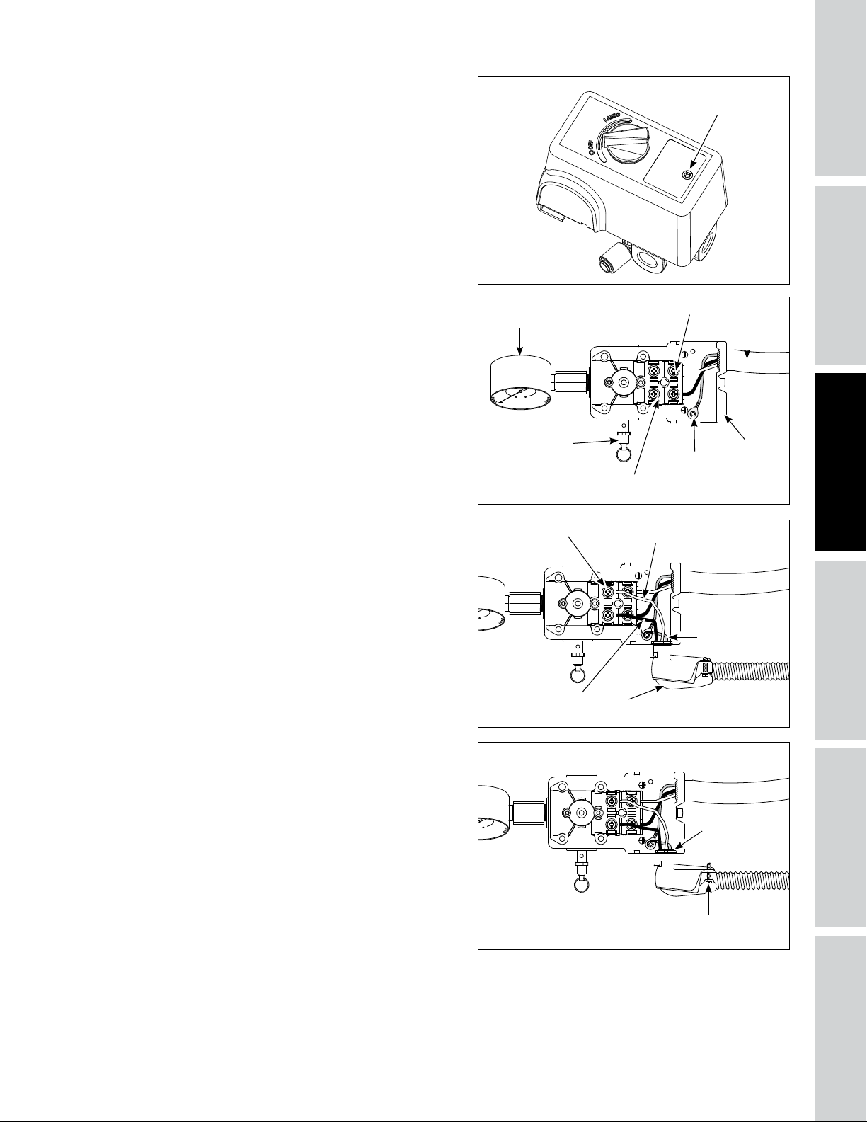
El voltímetro debe leer 120 Voltios.
Confirme el voltaje con un voltímetro de fase
a fase. Elvoltímetro debe leer 230 / 240 voltios
(consulte la figura 8).
2. Retire la cubierta del interruptor de presión
soltando el tornillo (consulte la figura 9). Utilice
un destornillador Phillips (no incluidas). Los
estilos de interruptor de presión pueden variar.
Tornillo
ESPECIFICACIONES
SEGURIDAD /
Figura 9
3. Una vez quitada la cubierta, familiarícese con el
interruptor de presión.
4. Quite el tornillo de puesta a tierra. Instale un
aliviador de tensión en el interruptor de presión.
no apriete el aliviador de tensión al cable
de alimentación hasta que el cableado esté
completo. Introduzca los conductores desnudos
(negro, blanco, desnudo/verde) a través del
aliviador de tensión.
Fije el cable de puesta a tierra desnudo/verde
al tornillo de puesta a tierra en el cuerpo del
interruptor de presión.
Busque las marcas de “hilo” en el interruptor de
presión. Instale los alambres de línea y ajuste los
tornillos terminales.
Indicador de
presión del tanque
Válvula de
seguridad ASME
Línea terminal
Figura 10
Tornillo de
terminal
Hilo conductor
Figura 11
negro
Motor terminal
Tornillo de
puesta a
tierra
Hilo conductor blanco
Aliviador de tensión para cable
Cable de
alimentación
del motor
Aliviador de
tensión para
el cable del
motor
Cable conductor
desnudo/verde
de puesta a
tierra
de alimentación
OPERACIONMONTAJE / INSTALACION
5. Apriete la tuerca del aliviador de tensión.
Coloque un destornillador de cabeza plana (no
incluidas) en las muescas elevadas y golpéelo
con un martillo (no incluidas) hasta que esté
apretado.
Apriete los tornillos del aliviador de tensión
para sujetar en forma segura el cable de
alimentación. Reemplace la cubierta del
interruptor de presión (la perilla debe estar en
la misma posición que cuando fue quitada para
colocarla en su lugar correctamente). Apriete
el tornillo del interruptor de presión con un
destornillador Phillips. Revise que el interruptor
esté en la posición de APAGADO. Siga el
procedimiento básico en página 13.
Sp11
Figura 12
Tuerca del
aliviador de
tensión
Tornillo del aliviador
de tensión
IDENTIFICACION
DE PROBLEMAS
MANTENIMIENTO
/ REPARACION
Page 58

INSTRUCCIONES DE INSTALACIÓN (CONTINUACIÓN)
PARA COMENZAR
SEGURIDAD /
ESPECIFICACIONES
Conexion a Tierra
Los artefactos eléctricos conectados a tierra incorrectamente constituyen un riesgo de
electrocutamiento. Cerciórese de que todas las conexiones a tierra estén hechas adecuadamente
para evitar la muerte o heridas de gravedad.
Este producto se debe conectar a tierra. Al conectarlo a tierra reduce el riesgo de choque eléctrico ya que,
si ocurre un cortocircuito, la conexión a tierra le ofrece un desvío a la corriente eléctrica. Este producto se
debe utilizar con un cordón eléctrico o cable que tenga conexión a tierra.
Instale el cableado permanente desde la fuente
eléctrica al interruptor de presión con un conductor
de puesta a tierra conectado al tornillo de puesta a
tierra en el interruptor de presión. El usuario también
puede instalar un cable del tamaño adecuado con un
conductor de puesta a tierra y un enchufe.
Filtro de aire
Instalación del filtro de aire
Instale un filtro de aire en la bomba (consulte lafigura
13). Los estilos de filtros pueden variar.
OPERACION MONTAJE / INSTALACION
DE PROBLEMAS
IDENTIFICACION
Lubricacion
ESTA UNIDAD NO TIENE ACEITE.
Llene hasta el centro del calibrador visual (ver Figura 15).
Si utiliza cualquier otro tipo de
duración del cabezal y dañar las válvulas.
Aceite recomendado (2 opciones)
Aceite no detergente para compresor de una sola
viscosidad SAE 30 ISO100. Número de parte ST125303AV
(0.47 L) o ST126701AV (3.79 L).
Aceite sintético 10W30 como el Mobil 1® o CE0032 (0.95
L).
Capacidad de aceite
Aproximadamente 1.40 L
Retire la tapa del recipiente de aceite de la bomba.
Verifique el nivel de aceite; algunos modelos se
envían con aceite en la bomba. Agregue aceite si es
necesario. Llene la bomba con aceite hasta el centro
del calibrador visual usando la abertura de llenado
de aceite (ver Figura 15). Coloque otra vez la tapa
del recipiente de aceite de la bomba.
bomba a través de la abertura de la tapa de la válvula de
aire ya que esto podría causar una pérdida de aceite y que
la misma rociara durante el funcionamiento.
No utilice aceite común para automóviles. Los
aditivos del aceite común de motor pueden causar
depósitos en la válvula y reducir la vida útilde la
bomba.
Para obtener la vida útil máxima para la bomba,
drene y reemplace el aceite luego de las primeras
50 horas de tiempo de funcionamiento y, luego,
siga el programa de mantenimiento regular que se
describe más adelante en el manual.
Antes de utilizar el compresor.
aceite podría disminuir la
NO llene la
Figura 13
Figura 14
Figura 15
Tapa del
recipiente
de aceite
Ventanilla
Tapón de desagüe
del aceite
Llena
Bajo
Ventanilla
Sp12
Page 59

Esta bomba tiene una ventanilla para ver el aceite, como se muestra en la figura 14. El nivel deaceite se
puede monitorear y mantener como se muestra en la figura 15.
NOTA: puede haber algo de aceite residual aún en la bomba por las pruebas realizadas en la fábrica que
dejan una capa fina en el calibrador visual, sin embargo, no hay aceite suficiente para hacer funcionar la
unidad.
INSTRUCCIONES DE OPERACIÓN
Arranque / Procedimiento básico
No utilice herramientas neumáticas para abrir el extremo de la manguera hasta que se complete
1. Devuelva la energía a la unidad desde la entrada principal.
2. Verifique el nivel de aceite según las instrucciones de la sección de lubricación de este manual.
3. Abra la válvula de drenaje del tanque (consulte la Figura 16). Gire la válvula de salida para abrir el flujo
de aire.
4. Mueva el interruptor de presión a la posición de AUTOMÁTICO para hacer funcionar la unidad (consulte
la figura 17).
5. Haga funcionar la unidad por treinta (30) minutos acero (0) PSI (sin carga) para asentar las partes de
labomba.
6. Mueva la palanca o perilla del interruptor de presión a la posición de APAGADO y gire la válvula de
desagüe del tanque para cerrar el flujo de aire. Elcompresor está listo para usarse.
7. Cambie el aceite después de las primeras cincuenta (50) horas de funcionamiento. Realice cambios de
aceite cada tres (3) meses o doscientas (200) horas de tiempo de funcionamiento, lo que ocurra primero.
el arranque y la revisión de la unidad esté correcta.
¡Nunca desconecte las uniones roscadas con presión en el tanque!
ESPECIFICACIONES
SEGURIDAD /
Tank Drain
Figura 16 Figura 17
Valve
Ciclos de encendido/apagado del compresor
Desagüe el tanque adiario para prevenir la corrosión y posibles lesiones debido a daños en el
entre 1,7 bar y 2,8 bar. No opere el desagüe con más de 2,8 bar en el tanque, de lo contrario, la válvula de desagüe puede
dañarse. Drene la humedad del tanque a diario con la válvula de drenaje en la parte inferior del tanque.
En la posición AUTOMÁTICO el compresor bombea aire al tanque. Cuando se alcanza la presión de apagado
(“presión de apagado” preestablecida), el compresor se apagará automáticamente.
Si se deja el compresor en la posición de AUTOMÁTICO y el aire se agota por el uso de un regulador
para neumáticos, herramienta, etc., el compresor se reiniciará automáticamente en la “presión de
encendido” preestablecida. Cuando se utiliza una herramienta en forma continua, el compresor alternará
automáticamente entre encendido y apagado.
En la posición APAGADO el compresor no funcionará.
tanque. Para el óptimo funcionamiento del desagüe del tanque, la presión del tanque debe estar
Desagüe líquidos del tanque todos los días.
OPERACIONMONTAJE / INSTALACION
IDENTIFICACION
DE PROBLEMAS
MANTENIMIENTO
/ REPARACION
Sp13
Page 60

INSTRUCCIONES DE OPERACIÓN (CONTINUACIÓN)
PARA COMENZAR
HUMEDAD EN EL AIRE COMPRIMIDO
La humedad que se acumula en el aire comprimido se convierte en gotas a medida que sale de la
bomba. Cuando el nivel de humedad es muy alto o cuando el compresor ha estado en uso continuo por
mucho tiempo, esta humedad se acumulará en el tanque. Cuando esté pintando o rociando arena, la
humedad saldrá del tanque mezclada con el material que esté rociando.
IMPORTANTE: Esta condensación ocasionará manchas en la pintura, especialmente cuando esté
pintando con pinturas que no sean a base de agua. Si está rociando arena, la humedad hará que la
arena se aglutine y obstruya la pistola. Un filtro en la línea de aire, ubicado lo más cerca posible de la
pistola, ayudará a eliminar esta humedad.
SEGURIDAD /
GUÍA DE DIAGNÓSTICO DE AVERÍAS
ESPECIFICACIONES
Baja presión de descarga 1. La demanda de aire excede la
Ruido excesivo (golpeteo) 1. La polea del motor o el volante están
OPERACION MONTAJE / INSTALACION
DE PROBLEMAS
IDENTIFICACION
Aceite excesivo en el aire de
descarga.
NOTA: En un compresor
lubricado con aceite siempre
hay una pequeña cantidad de
aceite en el flujo de aire.
PROBLEMA POSIBLE(S) CAUSA(S) ACCIÓN A TOMAR
capacidad de la bomba
2. Pérdidas de aire (conectores, tuberías
del compresor, oplomería exterior
alsistema)
3. Entrada de aire restringida 3. Limpie o reemplace el filtro de aire.
4. Juntas defectuosas 4. Reemplace cualquier junta que pruebe estar
5. Válvulas dañadas o con pérdidas. 5. Quite el cabezal e inspecciónelo para detectar
sueltos
2. Sujetadores sueltos en la bomba o el
motor
3. Falta de aceite en el cárter 3. Controle si el nivel de aceite es el adecuado; si está
4. Biela gastada 4. Reemplace la biela. Mantenga el nivel de aceite y
5. Diámetros del eje del émbolo
desgastados
6. El émbolo pega contra la placa de la
válvula
7. Válvula de verificación ruidosa en el
sistema del compresor
1. Aros del émbolo desgastados 1. Reemplácelos con aros nuevos. Mantenga el nivel de
2. La entrada de aire del compresor está
restringida
3. Demasiado aceite en el compresor 3. Escúrralo hasta que alcance el nivel de lleno.
4. Viscosidad del aceite equivocada 4. Utilice Mobil 1
1. Reduzca la demanda de aire o utilice un compresor
de mayor capacidad.
2. Escuche para detectar pérdidas de aire. Aplique
una solución jabonosa a todos los accesorios y
conexiones. Aparecerán burbujas en los puntos
donde existan pérdidas. Ajuste o reemplace los
accesorios o conexiones con pérdidas. Utilice cinta
selladora para roscas.
defectuosa al inspeccionarla.
posibles roturas de la válvula, válvulas desalineadas,
asientos de válvulas dañados, etc. Reemplace las
piezas defectuosas y vuelva a armar.
Instale una nueva junta para el
quitado.
1. Apriete los pernos de la abrazadera y tornillos de
fijación de la polea / volante.
2. Apriete los sujetadores.
bajo, verifique la posibilidad de que los cojinetes
estén dañados. El aceite sucio puede causar un
desgaste excesivo.
cambie el aceite con más frecuencia.
5. Quite los ensamblajes del émbolo del compresor e
inspecciónelos para detectar un desgaste excesivo.
Reemplace el eje del émbolo(s) si está excesivamente
desgastado o según necesario. Mantenga el nivel de
aceite y cambie el aceite con más frecuencia.
6. Quite el cabezal del compresor y la placa de la
válvula e inspeccione para detectar depósitos de
carbón u otros elementos extraños en la cabeza del
émbolo. Vuelva a colocar el cabezal y la placa de
la válvula utilizando una junta nueva. Consulte la
sección de lubricación para el aceite recomendado.
7. Reemplace la válvula de control.
No desarme la válvula de
en el tanque.
aceite y cambie el aceite con más frecuencia.
2. Limpie o reemplace el filtro. Verifique si hay otras
restricciones en la entrada del sistema.
cabezal cada vez que éste sea
verificación con presión de aire
®
10W-30 o sintético completo.
Sp14
Page 61

GUÍA DE DIAGNÓSTICO DE AVERÍAS
PROBLEMA POSIBLE(S) CAUSA(S) ACCIÓN A TOMAR
Agua en el aire de salida o en
el tanque
El motor zumba y funciona
lentamente o no funciona en lo
absoluto
El mecanismo de reinicio
de corta repetidas veces o
el interruptor de circuito se
dispara repetidas veces
El tanque no mantiene la
presión cuando el compresor
está apagado y la válvula de
apagado está cerrada
El interruptor de presión tira
continuamente aire por la
válvula de descarga
El interruptor de presión no
libera el aire cuando la unidad
de apaga
Vibración excesiva 1. Sujetadores sueltos en la bomba o el
Operación normal. La cantidad de agua
aumenta con el clima húmedo
1. El voltaje es bajo 1. Revise el ingreso de voltaje. Debe ser de 230
2. Muchos dispositivos en el mismo
circuito
3. Suelte las conexiones eléctricas 3. Revise todas las conexiones eléctricas.
4. El interruptor de presión está
defectuoso – los contactos no cerrarán
5. La válvula de control está defectuosa 5. Reemplace la válvula de control.
6. La válvula de descarga del interruptor
de presión está defectuosa
7. El(los) capacitor(es) del motor está
defectuoso
8. El motor está defectuoso 8. Reemplace el motor.
1. Falta de ventilación adecuada / la
temperatura ambiente es demasiado
alta
2. Muchos dispositivos en el mismo
circuito
3. Entrada de aire restringida 3. Limpie o reemplace el filtro.
4. Suelte la conexión eléctrica 4. Revise todas las conexiones eléctricas.
5. El interruptor de presión de apagado
está ajustado en un nivel muy elevado
6. La válvula de control está defectuosa 6. Reemplace la válvula de control.
7. La válvula de descarga del interruptor
de presión está defectuosa
8. El(los) capacitor(es) del motor está
defectuoso
9. El motor está defectuoso 9. Reemplace el motor.
1. Fugas de aire (conectores, tuberías
del compresor, o plomería exterior de
sistema)
2. Válvula de control desgastada 2. Reemplace la válvula de control.
3. Revise el tanque para ver si hay
grietas o perforaciones
Malfuncionamiento de la válvula Reemplace la válvula de control si la válvula de descarga
Malfuncionamiento de la válvula de
descarga en el interruptor de presión
motor
2. La correa necesita ser reempla zada 2. Reemplace la correa con otra del tamaño adecuado.
3. Alineación de la correa 3. Alinee el volante y la polea.
1. Drene el tanque con más frecuencia. Al menos
diariamente.
2. Agregue un filtro.
voltios aproximadamente. El motor no funcionará
correctamente a 208 voltios. El voltaje bajo puede
deberse a que los conductores (desde la fuente
eléctrica hasta el compresor) son de diámetro muy
pequeño y/o muy largos. Haga que los verifique un
electricista calificado y realice las reparaciones si es
necesario.
2. Limite el circuito sólo para el uso del compresor.
4. Reemplace el interruptor de presión.
No desarme la válvula de
verificación con presión de aire
en el tanque.
6. Reemplace la válvula de descarga.
7. Reemplace el(los) capacitor(es).
1. Mueva el compresor a un área bien ventilada.
2. Limite el circuito sólo para el uso de la compresora
de aire.
5. Reemplace el interruptor de presión.
No desarme la válvula de
verificación con presión de aire
en el tanque.
7. Reemplace la válvula de descarga.
8. Reemplace el(los) capacitor(es).
1. Compruebe todas las conexiones con una solución
de agua jabonosa. Apriete; o quite y aplique sellador
para roscas, luego vuelva a ensamblar.
No desarme la válvula de
verificación con presión de aire
en el tanque.
3. Reemplace el tanque. Nunca repare un
tanquedañado.
del interruptor de presión se purga constantemente
cuando la unidad se cierra.
No desarme la válvula de
verificación con presión de aire
en el tanque.
1. Reemplace el interruptor de presión si éste no libera
la presión por un breve período de tiempo cuando
se apaga la unidad.
No desarme el interruptor
depresión si hay presión en
eltanque.
1. Apriete los sujetadores.
ESPECIFICACIONES
SEGURIDAD /
OPERACIONMONTAJE / INSTALACION
IDENTIFICACION
DE PROBLEMAS
MANTENIMIENTO
/ REPARACION
Sp15
Page 62

INSTRUCCIONES DE MANTENIMIENTO E INSPECCIÓN
PARA COMENZAR
SEGURIDAD /
ESPECIFICACIONES
Desconecte el cordón eléctrico, amárrelo y aléjelo del tomacorrientes, después libere toda la
darle cualquier tipo de mantenimiento.
presión del tanque antes de tratar de instalar el compresor, darle servicio, moverlo de sitio o
Todas las reparaciones deben ser hechas por un representante de servicio autorizado.
Para mantener el funcionamiento eficiente del sistema del
compresor, chequée el filtro de aire y mida el nivel del aceite
antes de cada uso. La válvula de seguridad ASME también se
debe chequear a diario (Vea la Figura 18). Hále el anillo de la
válvula de seguridad y déjelo que regrese de nuevo en su posición
original. Esta válvula automáticamente li-bera el aire del tanque,
si la presión excede el nivel máximo fijado de fábrica. Si hay una
fuga de aire después que ha soltado el anillo, o si la válvula está
atascada y no la puede activar con el anillo, deberá reemplazar la
válvula de seguridad ASME.
No modifique la válvula de retención ASME.
Figura 18 - Válvula de seguridad ASME
Tanque
¡Nunca trate de reparar o modificar el tanque! Si lo suelda, taladra o modifica de cualquier otra
tanques desgastados, rotos o dañados.
Desagüe el tanque: Desconecte, etiquete y bloquee la fuente de alimentación; libere la presión. Drene la
humedad del tanque abriendo la válvula de drenaje debajo del tanque una vez que la presión del tanque
seainferior a 2,8 bar (Ver la figura 16 en la página Sp13).
El tanque se debe inspeccionar cuidadosamente por lo menos una vez al año. Cerciórese de que no haya
ranuras en las soldaduras. De haberlas, libere la presión del tanque inmediatamente y reemplácelo.
manera, el tanque se debilitará y se podría dañar al romperse o explotar. Siempre remplace los
Drene el líquido del tanque diariamente.
OPERACION MONTAJE / INSTALACION
DE PROBLEMAS
IDENTIFICACION
Lubricación del Compresor
Vea la sección de Funcionamiento Añádale aceite al cabezal cuando sea necesario. Debe cambiar el aceite y
el filtro cada 3 meses o después de 200 horas de funcionamiento; lo que ocurra primero.
Si el compresor se utiliza bajo condiciones húmedas por períodos cortos, la humedad se condensará en
la caja del cigüeñal y ocasionará que el aceite luzca cremoso. El aceite contaminado por el agua no le
proveerá la lubricación adecuada y lo debe cambiar inmediatamente. Si usa aceite contaminado, los
cojinetes, pistones, cilindros y anillos se dañarán y estos daños no están cubiertos por la garantía. Para evitar
la condensación del agua en el aceite, haga funcionar periódicamente el compresor con una presión de
tanque cercana a 8.3 bar para compresores de 2 etapas, abriendo la válvula de purga o una válvula de aire
conectada al tanque o la manguera. Deje que el cabezal funcione por una hora en estas condiciones por lo
menos una vez a la semana, o con más frecuencia, en caso de que el problema ocurra.
IMPORTANTE: Cámbiele el aceite después de 50 horas de operación.
Filtro de aire
Nunca utilice el cabezal del compresor sin instalarle el filtro de la
entrada de aire o con un filtro obstruído. El elemento del filtro
de aire debe verificarse mensualmente (verFigura 19). Si utiliza
el compresor con el filtro sucio, podría aumentar el consumo de
aceite y la contaminación con aceite del aire expulsado. Si el filtro
de aire está sucio, debe reemplazarse.
Sp16
Figura 19
Page 63

Correa
Apague el compresor, cerciórese de que el interruptor no se pueda activar y después libere la
presión del tanque, para evitar que la unidad se mueva sin previo aviso.
Chequée la tensión de las bandas cada 3 meses. Ajuste la tensión de las bandas para permitir una deflección
de 9,5 mm a 12,7 mm (3/8 pulg - 1/2 pulg) al ejercer una presión normal con el dedo. Igualmente, debe
alinear las bandas usando como referencia un objeto recto que toque el volante y dos puntos del borde a
ambos lados del volante. Las bandas deben estar paralelas a esta línea recta de referencia (vea la Figura 20).
Las distancias A, B y C deben ser iguales para asegurar que las bandas estén alineadas adecuadamente. Las
ranuras en la base le permiten mover el motor, en ambas direcciones, para ajustar la tensión de las bandas.
Polea del
motor
Motor
A B
Compresor de aire
Volante
Borde recto
ESPECIFICACIONES
SEGURIDAD /
Tornillo de fijación
C
Figura 20 - Vista superior
Retiro del protector de banda
Al retirar el protector de banda delantero para
clips de sujeción y reemplácelos si están dañados o si el clip puede
quitarse sin herramientas.
inspeccionar o cambiar las bandas, revise los
Retiro de los clips de sujeción
1. Usando una llave inglesa o pinzas, gire el clip 90°.
2. Jale el clip hacia afuera, separándolo del protector de
banda.
3. Realice el procedimiento a la inversa para reinstalar el clip
después de revisarlo.
Figura 21
Almacenamiento
Si va a almacenar el compresor por un período corto, cerciórese de que esté en su posición normal y en un
área fría y bien protegida.
PROGRAMA DE MANTENIMIENTO
Funcionamiento Diario Semanal
Revise el nivel de aceite
Desagüe el tanque
Verifique el filtro deaire
Verifique la válvula de seguridad
Limpie la unidad
Verifique la sujeción de la correa
Cambie el aceite*
* Cambie el aceite después de las primeras cincuenta (50) horas de funcionamiento, luego realice cambios de aceite
cada tres (3) meses o doscientas (200) horas de tiempo de funcionamiento, lo que ocurra primero.
l
l
l
l
1
2
Una vez al
mes 3 meses
l
l
l
OPERACIONMONTAJE / INSTALACION
IDENTIFICACION
DE PROBLEMAS
MANTENIMIENTO
/ REPARACION
Sp17
Page 64

ILUSTRACIÓN DE LOS REPUESTOS PARA CE5002 Y XC602100
PARA COMENZAR
3
2
SEGURIDAD /
ESPECIFICACIONES
OPERACION MONTAJE / INSTALACION
4
1
DE PROBLEMAS
IDENTIFICACION
Para repuestos, visite www.campbellhausfeld.com
24 horas al día, 365 días al año
Por favor proporcione la siguiente información:
- Número de modelo
- Número de serie (si lo tiene)
- Descripción de la parte y número que le corresponde en la lista de partes
Sp18
Page 65

LISTA DE REPUESTOS PARA CE5002 Y XC602100
No. de
Ref. Descripción
1
2
3
4
Tanque de 227,12 litros AR068400CG 1
Bomba alternativa de 2 etapas de 5 HP XC002500IP 1
Motor eléctrico de 3,5 HP MC019700IP 1
Interruptor de presión CW220000AV 1
Número de
Parte: Cant.
PIEZAS DE RECAMBIO DE LA UNIDAD
Ref.
No. Descripción
Válvula de drenaje SR060513SV 1
Polea del motor PU017300AV 1
Correa en V BT021501AV 1
Kit de válvula de retención/tubo de escape XC000800SV 1
Kit de interruptor de presión MY001000SV 1
Kit de protección de la correa BG900100SV 1
Número de
Parte: Cant.
PIEZAS DE RECAMBIO DE LA BOMBA
Ref.
No. Description Part Number: Qty.
Kit de reemplazo de la válvula XC001000AV 1
Kit de repuesto del anillo XC001100AV 1
Kit de empaque XC001300AV 1
Volante XC001400AV 1
Accesorios de la bomba XC001500AV 1
Elemento de filtro de aire XC001700AV 1
ESPECIFICACIONES
SEGURIDAD /
OPERACIONMONTAJE / INSTALACION
Sp19
IDENTIFICACION
DE PROBLEMAS
MANTENIMIENTO
/ REPARACION
Page 66

Recordatorio: ¡Guarde su comprobante de compra con fecha para fines de la garantía! Adjúntela a este manual o archívela en
lugar seguro.
GARANTÍA LIMITADA
1. DURACIÓN: Por el comprador desde la fecha de compra, de la siguiente manera: Tres años.
2. QUIÉN EMITE ESTA GARANTÍA: Campbell Hausfeld a Marmon/Berkshire Hathaway Company, 100 Production Drive, Harrison,
Ohio, 45030. Visite www.campbellhausfeld.com.
3. QUIÉN RECIBE ESTA GARANTÍA (COMPRADOR): El comprador original (para otro fin que no sea la reventa) del compresor.
4. QUÉ PRODUCTOS CUBRE ESTA GARANTÍA: Esta compresora de aire.
5. QUÉ CUBRE ESTA GARANTÍA: Las piezas y mano de obra para solucionar los defectos importantes que presente de material
y de fabricación durante el primer año de propiedad con las excepciones que se indican a continuación. Las piezas sólo para
solucionar los defectos importantes que presente de material y de fabricación durante el tiempo restante de cobertura con
las excepciones que se indican a continuación.
6. QUÉ NO CUBRE ESTA GARANTÍA:
A. Las garantías implícitas, incluidas las de comerciabilidad e IDONEIDAD PARA UN FIN EN PARTICULAR, SE LIMITAN A
PARTIR DE LA FECHA DE LA COMPRA ORIGINAL DE ACUERDO CON LO ESPECIFICADO EN EL PÁRRAFO DE DURACIÓN.
Algunos estados no permiten limitaciones sobre la duración de una garantía implícita, de modo que las limitaciones
antes descritas puede que no se apliquen en su caso
B. CUALQUIER PÉRDIDA, DAÑO O GASTO ACCIDENTAL, INDIRECTO O RESULTANTE, QUE SE ORIGINE POR DEFECTO, FALLA
O FUNCIONAMIENTO INCORRECTO DEL PRODUCTO CAMPBELL HAUSFELD. Algunos estados no permiten la exclusión
o limitaciones de los daños accidentales o resultantes, de modo que la exclusión o limitación anterior puede que no se
aplique en su caso.
C. Cualquier falla que se origine de un accidente, abuso del comprador, negligencia o falla para operar los productos de
acuerdo con las instrucciones provistas en el manual(es) del propietario suministrado con el compresor.
D. Servicio de preentrega, por ej. ensamblado, aceite o lubricantes, y ajustes.
E. Artículos o servicio que se necesitan normalmente para mantener el producto, por ej. lubricantes, filtros y
empaquetaduras, etc.
F. Artículos adicionales que no están cubiertos por esta garantía:
1. Artículos excluidos correspondientes a todos los compresores
a. Cualquier componente dañado durante el envío o cualquier daño ocasionado por haber instalado u operado
la unidad bajo condiciones contrarias a lo indicado en las instrucciones para instalar u operar la unidad o daños
ocasionados por el contacto con herramientas o los alrededores.
b. Daños en la bomba o las válvulas ocasionados por la lluvia, humedad excesiva, agentes corrosivos u otros
contaminantes.
c. Defectos cosméticos que no interfieren con el funcionamiento del compresor.
d. Tanques oxidados, incluyendo, entre otros, el óxido debido al drenaje inadecuado o a agentes corrosivos en el
ambiente.
e. Los siguientes componentes se consideran artículos de uso normal y no son cubiertos después del primer año
de propiedad. Motor eléctrico, válvula de control, interruptor de presión, regulador, indicadores de presión,
mangueras, tuberías, tubos, conectores yacoples, tornillos, tuercas, artículos de ferretería, correas, poleas,
volante, filtro de aire y carcasa, empaquetaduras, sellos, filtraciones de aceite, filtraciones de aire, consumo o
uso de aceite, anillos del pistón.
f. Válvulas de drenaje del tanque.
g. Daños debidos al cableado incorrecto o conexión a circuitos con voltaje inadecuados para la unidad.
h. Otros artículos no mencionados pero que se consideran piezas de uso general.
i. Interruptores de presión, controladores de flujo de aire, dispositivos de carga/descarga, dispositivos de control
de aceleración y válvulas de seguridad modificados de fábrica.
j. Daño por mantenimiento inadecuado del filtro.
k. Motores de inducción operados con electricidad producida por un generador.
2. Artículos excluidos específicos para compresores lubricados:
a. Desgaste de la bomba o daño a las válvulas debido al uso de aceites no especificados.
b. Desgaste o daño de la bomba causado por cualquier tipo de contaminación del aceite.
c. Desgaste o daño de la bomba por no seguir las pautas de mantenimiento del aceite apropiadas, por
G. Mano de obra, servicio de llamada, o cargos por transporte después del primer año de propiedad de los compresores
estacionarios. Los compresores estacionarios se identifican por no tener manija o ruedas.
7. RESPONSABILIDADES DEL GARANTE QUE CUBRE ESTA GARANTÍA: El fabricante, a su criterio, reparará o reemplazará este
producto o cualquier componente de éste que presente defectos durante el período de vigencia de la garantía.
8. RESPONSABILIDADES DEL COMPRADOR QUE CUBRE ESTA GARANTÍA:
A. Proporcionar el comprobante de la fecha de compra y registros de mantenimiento.
B. Visite www.campbellhausfeld.com para ver sus opciones de servicio de garantía. Los costos de flete deben ser asumidos
por el comprador.
C. Prestar el cuidado adecuado al operar y hacerle mantenimiento a los productos como se indica en el (los) manual(es) del
propietario.
D. Reparaciones que requieran tiempo adicional al horario normal de trabajo, tarifas de fin de semana o cualquier
reparación que exceda las tarifas estándar de trabajos de reparación de la garantía del fabricante.
E. El tiempo requerido por el personal de servicio para obtener el acceso al local para revisiones de seguridad, capacitación
de seguridad o similar.
F. La ubicación de la unidad debe tener espacio adecuado y ser de fácil acceso para que el personal de servicio realice las
reparaciones.
9. CUÁNDO EL GARANTE REALIZARÁ REPARACIONES O REEMPLAZOS QUE CUBRE ESTA GARANTÍA: La reparación o reemplazo
dependerá del flujo normal de trabajo del centro de servicio y de la disponibilidad de las piezas de repuesto.
Esta garantía limitada se aplica en los Estados Unidos Canadá y México, y le da derechos legales específicos. Usted también puede
tener otros derechos que varían según el estado o país.
funcionamiento con un nivel de aceite inferior al adecuado o por funcionamiento sin aceite.
Sp20
 Loading...