

Installation Instructions Model WT2530
Please read and save these instructions. Read carefully before attempting to assemble, install, operate or maintain the product described. Protect yourself and
others by observing all safety information. Failure to comply with instructions could result in personal injury and/or property damage! Retain instructions for
future reference.
Aluminum
BU IL T TO L AS T
Welding Kit
Description
Model WT2530 is an aluminum welding
kit designed for use on all Campbell
Hausfeld wire feed MIG welders (WG
series). This kit includes: PTFE wire liner
(Part Number: WC600210AV) , smoothgroove drive roller (Part Number:
WC500008AV) and four pieces of
0.030" (0.8 mm) aluminum contact tips
(Part Number: WT501800AV). These
parts, when installed in your welder,
allow welding aluminum with greater
success. Along with this kit, you will
need a spool of 0.030" (0.8 mm)
aluminum MIG wire (Part Number:
WE303001AV) and a bottle of 100%
Argon shielding gas (Part Number:
WT601100AV).
PTFE wire liner
The PTFE wire liner reduces the drag on
the soft aluminum welding wire. DO
NOT USE TO WELD STEEL. This liner
should be used for aluminum welding
only to prevent contamination.
1. Verify the welder is OFF and
UNPLUGGED.
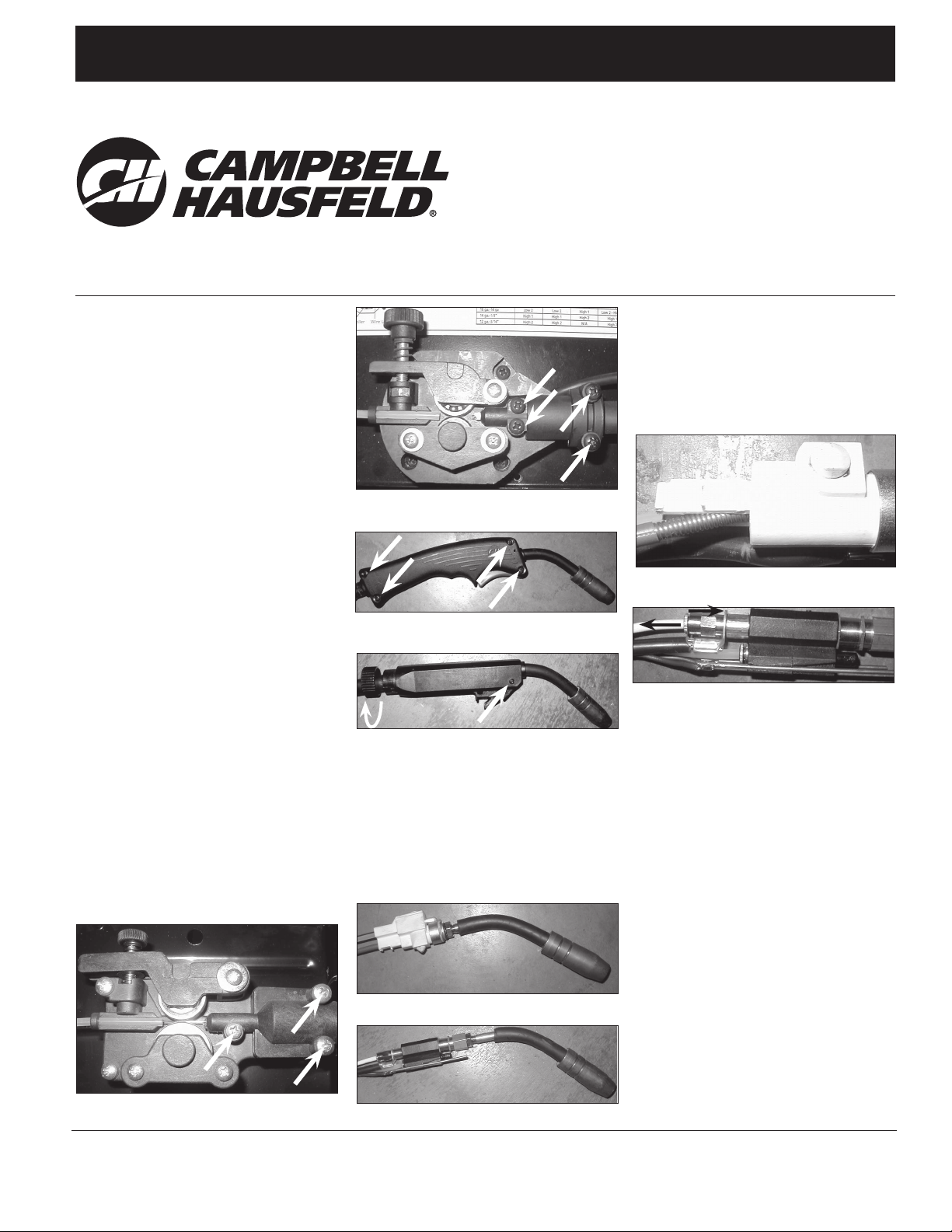
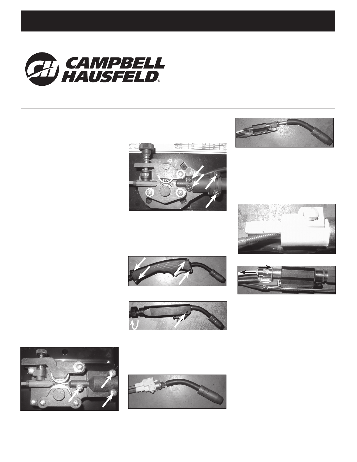
2. Open wire feed door and locate
drive deck. Remove torch cable
cover by removing three screws (see
figure 1a). WG3020: Remove four
screws (see figure 1b).
3. Disassemble torch handle by
Figure 1b – Remove these four screws
Figure 2a – Remove these four screws
Figure 2b – Remove screw and twist nut
removing four screws (see figure
2a). WG3020: Remove one screw
and twist nut (see figure 2b).
4. Remove swan neck/valve assembly
from handle (see figure 3a).
WG3020: (see figure 3b).
5. Remove the existing wire liner from
Swan Neck
Valve
Figure 3a
Swan Neck
the valve. Unlock by pulling up,
then out from the valve (see figure
4a). WG3020: Pull liner from valve
while pressing collar of liner fitting
(see figure 4b).
6. Straighten the torch hose and
Figure 4a
Figure 4b
remove the existing wire liner. Then,
insert the PTFE wire liner into the
torch hose.
7. Push new liner into the valve at an
angle until seated fully and then
push sideways to lock it in position
(see figure 4a). WG3020: Push new
liner into fitting. It locks
automatically.
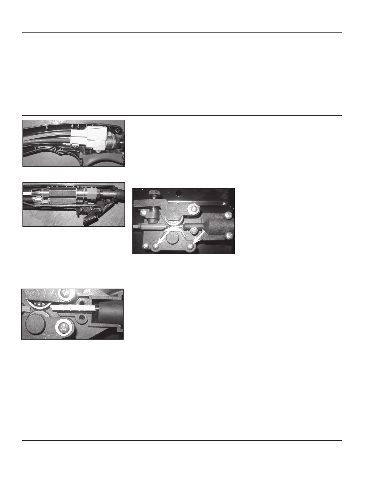
8. Place swan neck/valve assembly into
torch handle, making sure small
black wires are located correctly (see
figure 5a). Reassemble torch handle
with four screws. WG3020: Make
sure trigger is positioned correctly
(see figure 5b).
Figure 1a – Remove these three screws
© 2002 Campbell Hausfeld/Scott Fetzer
Valve
Figure 3b
For parts, manuals, product & service information
visit www.chpower.com
or call 1-800-746-5641
IN971100AV 3/02
Installation Instructions
Aluminum Welding Kit
Figure 5a
Figure 5b
9. Reattach torch cable cover onto
drive deck, making sure wire liner is
aligned with drive roller, but not
touching the roller (see figure 6).
Note: Trim the liner’s length as
needed.
Figure 6
Smooth-Groove Drive Roller
The existing serrated-groove drive roller
will cut notches in the soft aluminum
welding wire. These notches increase
the drag within the wire liner. The
smooth-groove drive roller eliminates
this problem. WG3020: Use the smoothgroove drive roller supplied with your
welder.
1. Verify the welder is OFF and
UNPLUGGED.
2. Open wire feed door and locate
drive deck. Release tension on swing
arm by removing tension screw and
spring.
3. Remove roller cover by removing
two screws (see figure 7).
Figure 7 – Remove these two screws
4. Remove serrated-groove drive roller
and replace with smooth-groove
drive roller. Install drive roller with
"0,8-0,9" stamping facing out. This
aligns the correct groove for 0.030"-
0.035" (0.8-0.9 mm) wire with the
liner.
5. Reinstall roller cover, tension screw
and spring.
Aluminum Contact Tip
The contact tips in this kit have been
designed specifically for welding
aluminum. The hole is slightly oversized
to reduce drag. There is more mass to
handle the extra heat associated with
aluminum welding. And, the tip is
tapered for use with shielding gases.
These tips are to be used with 0.030"
(0.8 mm) aluminum MIG wire.
1. Remove nozzle by turning
counterclockwise.
2. Remove existing contact tip by
turning counterclockwise.
3. Install 0.030" (0.8 mm) aluminum
contact tip.
4. Reinstall nozzle.
Aluminum Welding Help
• Make sure your base metal is very
clean. New aluminum will oxidize
almost immediately. Thin layers of
oxidation are clear and cannot be
seen. Use a stainless steel brush to
clean the weld area and the work
clamp area. Use the stainless steel
brush only on aluminum to prevent
contamination.
• The center of the contact tip must be
clean to transfer the current required
for welding aluminum. Even new
contact tips can benefit from cleaning
with a tip cleaner.
• Since aluminum conducts heat so
well, higher welder output is
required. Also, the wire and travel
speeds need to be faster.
• Work clamp connection must be
thoroughly clean and as close to the
weld area as possible.
• When welding thin material, it is
usually easier to use a "push"
technique rather than a "pull"
technique.
www.chpower.com
2
Instructions de Montage Modèle WT2530
S’il vous plaît lire et conserver ces instructions. Lire attentivement avant de monter, installer, utiliser ou de procéder à l’entretien du produit décrit. Se protéger
ainsi que les autres en observant toutes les instructions de sécurité, sinon, il y a risque de blessure et/ou dégâts matériels! Conserver ces instructions comme
référence.
Kit de Soudure
BU IL T TO L AS T
d’Aluminium
Description
Le modèle WT2530 est un kit de soudure
d'aluminium conçu pour toutes les
soudeuses à l'arc sous la protection de
gaz inerte avec fil électrode fusible à
entraînement du fil électrode Campbell
Hausfeld (série WG). Cette trousse
comprend : Chemise de fil de PTFE (no de
pièce : WC600210AV), rouleau
d’entraînement à rainure lisse (no de
pièce : WC500008AV), quatre pointes de
contact de 0,8 mm (0,030 po)
d’aluminium (no de pièce :
WT501800AV). Ces pièces, installées sur
votre soudeuse, permettent de souder
l'aluminium avec plus de succès. Avec ce
kit, vous aurez besoin d'une bobine de fil
MIG d'aluminium de 0,030 pouce (0,8
mm) (numéro de pièce: WE303001AV) et
d'une bouteille de gaz de protection
d'argon à 100 % (numéro de pièce:
WT601100AV).
Chemise de fil de PTFE
La chemise de fil de PTFE réduit la
traînée sur le fil de soudage d'aluminium
doux. N'UTILISEZ PAS POUR SOUDER
L'ACIER Cette garniture devrait servir
seulement pour la soudure d'aluminium
afin de prévenir la contamination.
1. Vérifiez que l'appareil est hors
tension et DÉBRANCHÉ.
2. Ouvrez la porte d'alimentation du fil
et trouvez le plateau d'alimentation.
Figure 1a – Retirez ces trois vis
Retirez le couvercle du câble du
chalumeau en retirant trois vis (voir
la figure 1a). WG3020: Retirez les
quatre vis (voir la figure 1b).
Figure 1b – Retirez ces quatre vis
3. Démontez la poignée du chalumeau
en retirant les quatre vis (voir la
figure 2a). WG3020: Retirez une vis
et tournez l'écrou (voir la figure 2b).
Figure 2a – Retirez ces quatre vis
Figure 2b – Retirez la vis et tournez l’écrou
4. Retirez le montage du col de cycle/
soupape de la poignée (voir la figure
3a). WG3020: (voir la figure 3b).
Col de cygne
Soupape
Figure 3a
Col de
cygne
Soupape
Figure 3b
5. Retirez la garniture du fil actuelle de
la soupape. Déverrouillez en tirant
vers le haut, puis sortez de la
soupape (voir la figure 4a). WG3020:
Retirez la garniture de la soupape
tout en pressant le collier du raccord
de la garniture (voir la figure 4b).
Figure 4a
Figure 4b
6. Redressez le flexible du chalumeau
et retirez la garniture du fil actuelle.
Puis insérer la nouvelle chemise de fil
de PTFE dans le tuyau du chalumeau.
7. Poussez la nouvelle garniture dans la
soupape de biais jusqu'à ce qu'elle
soit bien installée, puis poussez de
côté pour verrouiller en place (voir la
figure 4a). WG3020: Poussez la
nouvelle garniture dans le raccord.
Elle se verrouille automatiquement.
8. Placez le montage du col de cygne/
soupape dans la poignée du
chalumeau en vous assurant que les
petits fils noirs soient bien placés
(voir la figure 5a). Remontez la
poignée du chalumeau avec quatre
© 2002 Campbell Hausfeld/Scott Fetzer
IN971100AV 3/02

Instructions de Montage
Kit de Soudure d’Aluminium
vis. WG3020: Assurez-vous que la
gâchette soit bien placée (voir la
figure 5b).
Figure 5a
Figure 5b
9. Remontez le couvercle du câble du
chalumeau sur le plateau
d'entraînement en vous assurant
que la garniture du fil soit alignée
avec le dévidoir, mais sans toucher le
rouleau (voir la figure 6).
Remarque: Taillez la longueur de
garniture au besoin.
Figure 6
Dévidoir à rainure lisse
Le dévidoir à rainure dentelée fera des
encoches dans le fil de soudure
d'aluminium mou. Ces encoches
augmentent la traînée de la garniture
du fil. Le dévidoir à rainure lisse élimine
ce problème. WG3020: Utilisez le
dévidoir à rainure lisse fourni avec votre
soudeuse.
1. Vérifiez que l'appareil est hors
tension et DÉBRANCHÉ.
2. Ouvrez la porte d'alimentation du fil
et trouvez le plateau d'alimentation.
Dégagez la tension sur le bras
pivotant en retirant la vis de tension
et le ressort.
3. Retirez le couvercle du rouleau en
retirant deux vis (voir la figure 7).
Figure 7 – Retirez ces deux vis
4. Retirez le dévidoir à rainure
dentelée et remplez-le avec un
dévidoir à rainure lisse. Installez le
dévidoir avec l'estampage "0,8 - 0,9
po" vers l'extérieur. Ceci aligne la
bonne rainure pour le fil 0.030-0.035
pouce (0,8-0,9 mm) avec la
garniture.
5. Réinstallez le dévidoir, la vis de
tension et le ressort.
Tube contact d'aluminium
Les tubes contact dans ce kit ont été
conçus spécifiquement pour la soudure
d'aluminium. Le trou est un peu
surdimensionné pour réduire la traînée.
Il y a plus de masse pour traiter la
chaleur supplémentaire associée à la
soudure d'aluminium. Le tube est effilé
pour l'utiliser avec les gaz de
protection. Ces tubes doivent être
utilisés avec le fil MIG d'aluminium de
0.030 po (0,8 mm).
1. Retirez l'embout en tournant dans
le sens antihoraire.
2. Retirez le tube contact actuel en
tournant dans le sens antihoraire.
3. Installez le tube contact
d'aluminium de 0.030 po (0,8 mm).
4. Réinstallez l'embout.
Aide pour la soudure d'alumini
um
• Assurez-vous que votre base de métal
soit très propre. Le nouvel aluminium
s'oxydera presque immédiatement.
Les minces couches d'oxydation sont
transparentes et ne peuvent pas être
vues. Utilisez une brosse d'acier
inoxydable pour nettoyer la région
de soudure et la région du dispositif
de serrage. Utilisez la brosse d'acier
inoxydable seulement sur l'aluminium
pour éviter la contamination.
• Le centre du tube contact doit être
propre pour transférer le courant
requis pour la soudure d'aluminium.
Même les nouveaux tubes contact
peuvent tirer profit d'un nettoyage
avec un nettoyeur de tube.
• Puisque l'aluminium conduit la
chaleur si bien, il faut une sortie de
soudure plus élevée. De même, la
vitesse de déplacement et du fil doit
être plus rapide.
• La connexion du dispositif de serrage
doit être bien propre et aussi près
que possible de la région de soudure.
• En soudant un matériau mince, il est
normalement plus facile d'utiliser une
technique de "pousser" plutôt
qu'une technique de "tirer".
4 - Fr

Instrucciones para la Instalación Modelo WT2530
Sírvase leer y guardar estas instrucciones.Lea con cuidado antes de tratar de armar, instalar, manejar o darle servicio al producto descrito en este manual. Protéjase
Ud. y a los demás observando todas las reglas de seguridad. El no seguir las instrucciones podría resultar en heridas y/o daños a su propiedad.Guarde este manual
como referencia.
Juego de
BU IL T TO L AS T
Des crip ción
El Mo de lo WT2530 es un jue go de sol dadu ra de alu mi nio di se ña do pa ra usar en
to das las sol da do ras MIG de ali men tación de alam bre de Cam pbell Haus feld
(se rie WG). Este juego incluye: Forro del
alambre en PTFE (No. de Pieza:
WC403621AV), del portabobinas de
ranuras suaves (No. de Pieza:
WC500008AV), y cuatro puntas de
contacto de aluminio de 0,8 mm
(0,030 pulg.) (No. de
Pieza: WT501800AV). Es tas pie zas, cuando se ins ta lan en su sol da do ra, le per miten un éxi to ma yor con la sol da du ra de
alu mi nio. Jun to con es te jue go, ne ce si tará una bo bi na de alam bre MIG de alu minio de 0,8 mm (0,030") (Nú me ro de pieza WE303001AV) y un tan que de gas
pro tec tor de Ar gón 100% (Nú me ro de
pie za: WT601100AV).
Soldadura de
Aluminio
rar la ta pa del ca ble del so ple te (vea
la fi gu ra 1a). WG3020: Qui te cua tro
tor ni llos (vea la fi gu ra 1b).
Figura 1b - Quite estos cuatro tonillos
3. De sar me el man go del so ple te quitan do cua tro tor ni llos (vea la fi gu ra
2a). WG3020: Qui te un tor ni llo y gi re
la tuer ca (vea la fi gu ra 2b).
Cuello de
cisne
Válvula
Figura 3b
del fo rro des de la vál vu la mien tras
pre sio na el cas qui llo del mon ta je del
fo rro (vea la fi gu ra 4b).
Figura 4a
Forro de alambre de PTFE
El forro de alambre de PTFE reduce la
resistencia sobre el alambre suave para
soldadura de aluminio. NO USAR PA RA
SOL DAR ACE RO. Es te fo rro de be usar se
só lo pa ra la sol da du ra de alu mi nio pa ra
evi tar la con ta mi na ción.
1. Ve ri fi que que la sol da do ra es té APA-
GA DA y DE SEN CHU FA DA.
2. Abra la puer ta de ali men ta ción del
alam bre y ubi que la pla ca de con ducción. Qui te los tres tor ni llos pa ra re ti-
Figura 1a - Quite estos tres tornillos
© 2002 Campbell Hausfeld/Scott Fetzer
Figura 2a - Quite estos cuatro tornillos
Figura 2b - Quite el tonillo y gire la tuerca
4. Qui te el en sam bla je de cue llo de cisne /vál vu la del man go (vea la fi gu ra
3a). WG3020: (vea la fi gu ra 3b).
5. Qui te el fo rro del alam bre exis ten te
de la vál vu la. Des tra be ti ran do ha cia
arri ba y lue go ha cia fue ra de la válvu la (vea la fi gu ra 4a). WG3020: Ti re
Cuello de
cisne
Válvula
Figura 3a
Figura 4b
6. En de re ce la man gue ra del so ple te y
qui te el fo rro del alam bre exis ten te.
Luego introduzca el forro de PTFE del
alambre dentro de la manguera del
soplete.
7. Em pu je en án gu lo el fo rro nue vo
den tro de la vál vu la has ta que se
apo ye to tal men te y lue go em pu je
ha cia los la dos pa ra tra bar lo en su
po si ción (vea la fi gu ra 4a). WG3020:
Em pu je el fo rro nue vo en el cas qui llo.
Se tra ba au to má ti ca men te.
8. Co lo que el en sam bla je de cue llo de
cis ne /vál vu la den tro del man go del
so ple te, ase gu rán do se de que los
alam bres ne gros es tén ubi ca dos
co rrec ta men te (vea la fi gu ra 5a).
Vuel va a ar mar el man go del so ple te
con los cua tro tor ni llos. WG3020: Asegú re se de que el ga ti llo es té en la
IN971100AV 3/02

Instrucciones de Instalación
Juego de Soldadura de Aluminio
po si ción ade cua da (vea la fi gu ra 5b).
Figura 5a
Figura 5b
9. Vuel va a co lo car la ta pa del ca ble
del so ple te so bre la pla ca de con ducción, ase gu rán do se de que el fo rro
del alam bre es té ali nea do con la
bo bi na, pe ro sin to car la (vea la fi gura 6). No ta: Cor te el fo rro del lar go
que sea ne ce sa rio.
Figura 6
Guía de ra nu ras sua ves
La guía de ra nu ras se rra das exis ten te
cor ta mues cas en el sua ve alam bre de
sol da du ra de alu mi nio. Es tas ra nu ras
au men tan la re si sten cia den tro del
fo rro del alam bre. La guía de ra nu ras
sua ves eli mi na es te pro ble ma. WG3020:
Use la guía de ra nu ras sua ves que se
pro por cio nó con su sol da do ra.
1. Ve ri fi que que la sol da do ra es té APA-
GA DA y DE SEN CHU FA DA.
2. Abra la puer ta de ali men ta ción del
alam bre y ubi que la pla ca de conduc ción. Li be re la ten sión del bra zo
os ci lan te qui tan do el tor ni llo y re sorte de ten sión.
3. Qui te dos tor ni llos pa ra re ti rar la
ta pa de la guía (vea la fi gu ra 7).
Figura 7 - Quite estos dos tornillos
4. Qui te la guía de ra nu ras se rra das y
reem plá ce la con la de ra nu ras suaves. Ins ta le la guía con el tro que la do
"0,8-0,9" ha cia fue ra. Es to ali nea la
ra nu ra co rrec ta pa ra el alam bre de
0,8-0,9 mm (0,030"-0,035") con el
fo rro.
5. Vuel va a co lo car la ta pa del ro di llo,
el tor ni llo y el re sor te de ten sión.
Pun ta de con tac to de
alu mi nio
Las pun tas de con tac to en es te jue go
fue ron di se ña das es pe cí fi ca men te pa ra
sol dar alu mi nio. El ori fi cio es ape nas
más gran de pa ra re du cir la re sis ten cia.
Es de cir más ma sa pa ra ma ne jar el ca lor
adi cio nal aso cia do con la so la du ra de
alu mi nio. Y la pun ta es ahu sa da pa ra
usar con ga ses de pro tec ción. Es tas puntas son pa ra usar con alam bre MIG de
alu mi nio de 0,8 mm (0,030").
1. Qui te la bo qui lla gi ran do ha cia la
iz quier da.
2. Qui te la pun ta de con tac to exis ten te
gi ran do ha cia la iz quier da.
3. Ins ta le la pun ta de con tac to de alumi nio de 0,8 mm (0,030").
4. Vuel va a co lo car la bo qui lla.
Ayu da pa ra la sol da du ra de alumi nio
• Ase gú re se de que su me tal bá si co
es té bien lim pio. El alu mi nio nue vo se
oxi da ca si de in me dia to. Las del ga das
ca pas de oxi da ción son trans pa ren tes
y no se pue den ver. Use un ce pi llo de
ace ro ino xi da ble pa ra lim piar el área
a sol dar y el área de la gra pa de traba jo. Use el ce pi llo de ace ro ino xi dable so la men te so bre alu mi nio pa ra
evi tar la con ta mi na ción.
• El cen tro de la pun ta de con tac to
de be es tar lim pio pa ra trans fe rir la
co rrien te ne ce sa ria pa ra la sol da du ra
de alu mi nio. In clu so las pun tas de
con tac to nue vas se pue den be ne fi ciar
si se las lim pia con un lim pia dor de
pun tas.
• Co mo el alu mi nio es tan buen con-
duc tor de ca lor, se ne ce si ta un ma yor
ni vel de sa li da de la sol da do ra. También la ve lo ci dad de des pla za mien to
y del alam bre de ben ser ma yo res.
• La co ne xión de la gra pa de tra ba jo
de be es tar to tal men te lim pia y lo más
cer ca na po si ble al área a sol dar.
• Cuan do se suel da ma te rial del ga do,
ge ne ral men te es más sen ci llo usar
una téc ni ca de "em pu je" en lu gar de
una téc ni ca de "ti ra do".
6 - Sp

Notes
Notas
Model WT2530
7

Notes
Notas
Model WT2530
 Loading...