

Page 1
Manual de Instrucciones de Operación y Lista de Piezas
24 Sp
Serie DC0100, FP2098
Garantía Limitada
1. DURACION: A partir de la fecha de compra por el comprador original tal como se especifica a continuación: Un año.
2. QUIEN OTORGA ESTA GARANTIA (EL GARANTE: Campbell Hausfeld a Marmon/Berkshire Hathaway Company, 100
Production Drive, Harrison, Ohio 45030 Teléfono: (800) 543-6400
3. QUIEN RECIBE ESTA GARANTIA (EL COMPRADOR): El comprador original (que no sea un revendedor) del producto
Campbell Hausfeld.
4. PRODUCTOS CUBIERTOS POR ESTA GARANTIA: Este compresor de aire Campbell Hausfeld.
5. COBERTURA DE LA GARANTIA: Los defectos substanciales de material y fabricación que ocurran dentro del período de
validez de la garantía.
6. LO QUE NO ESTA CUBIERTO POR ESTA GARANTIA:
A. Las garantías implícitas, incluyendo aquellas de comerciabilidad E IDONEIDAD PARA FINES PARTICULARES, ESTÁN
LIMITADAS A PARTIR DE LA FECHA DE COMPRA ORIGINAL A LO ESPECIFICADO EN EL PÁRRAFO DE DURACIÓN.
Si el compresor de aire es empleado para uso comercial, industrial o para renta, la garantía será aplicable por
noventa (90) días a partir de la fecha de compra. En algunos estados no se permiten limitaciones a la duración de
las garantías implícitas, por lo tanto, en tales casos esta limitación no es aplicable.
B. CUALQUIER PERDIDA, DAÑO INCIDENTAL, INDIRECTO O CONSECUENTE QUE PUEDA RESULTAR DE UN DEFECTO,
FALLA O MALFUNCIONAMIENTO DEL PRODUCTO CAMPBELL HAUSFELD. En algunos estados no se permite la
exclusión o limitación de daños incidentales o consecuentes, por lo tanto, en tales casos esta limitación o exclusión
no es aplicable
C. Cualquier falla que resulte de un accidente, abuso, negligencia o incumplimiento de las instrucciones de
funcionamiento y uso indicadas en el (los) manual(es) que se adjunta(n) al compresor.
D. Servicio previo a la entrega, p. ej. ensamblado, aceite o lubricantes y ajuste.
E. Artículos o servicio que se requieren normalmente para mantener el producto, p. ej. lubricantes, filtros y juntas,
etc.
F. Artículos adicionales no cubiertos bajo esta garantía:
1. Cualquier componente dañado durante el envío o cualquier daño ocasionado por haber instalado u operado la
unidad bajo condiciones contrarias a lo indicado en las instrucciones para instalar u operar la unidad o daños
ocasionados por el contacto con herramientas o los alrrededores.
2. Daños del cabezal o las válvulas ocasionados por la lluvia, humedad excesiva, agentes corrosivos u otros
contaminantes.
3. Daños de apariencia que no afecten el funcionamiento del compresor.
4. Tanques oxidados, incluyendo pero no limitado al óxido debido al drenaje inadecuado u agentes corrosivos en
el ambiente.
5. Llaves de drenaje
6. Daños debidos al alambrado incorrecto o conexión a circuitos con voltaje inadecuados para la unidad.
7. Otros artículos no enumerados pero considerados de desgaste general.
8. Presostatos, controles de flujo de aire y válvulas de seguridad cuyos parámetros fijados de fábrica se
modifiquen.
9. Bandas
10. Daños de los anillos debido al mantenimiento inadecuado del filtro.
7. RESPONSABILIDADES DEL GARANTE BAJO ESTA GARANTIA: Según elija el Garante, la reparación o el reemplazo del
producto o los componentes que estén defectuosos, que hayan funcionado en forma inadecuada y/o que no hayan
cumplido con su función dentro de la duración del período específico de la garantía.
8. RESPONSABILIDADES DEL COMPRADOR BAJO ESTA GARANTIA:
A. Suministrar prueba fechada de compra y la historia de mantenimiento del producto.
B. Entregar o enviar los compresores de aire portátiles o componentes lal Centro de Servicio autorizado Campbell
Hausfeld más cercano. Los gastos de flete, de haberlos, deben ser pagados por el comprador.
C. Tener cuidado al utilizar el producto, tal como se indica(n) en el (los) manual(es) del propietario.
9. EN QUÉ CASOS EL GARANTE PROPORCIONARÁ REEMPLAZO DE ACUERDO A ESTA GARANTÍA: El reemplazo será
planificado de acuerdo a la disponibilidad de compresores de repuesto o piezas.
Esta garantía limitada es válida sólo en los EE.UU., Canadá y México y otorga derechos legales específicos. Usted también
puede tener otros derechos que varían de un Estado a otro o de un país a otro.
Please read and save these instructions. Read carefully before attempting to assemble, install, operate or maintain the product described.
Protect yourself and others by observing all safety information. Failure to comply with instructions could result in personal injury and/or
property damage! Retain instructions for future reference.
REMINDER: Keep your dated proof of purchase for warranty purposes!
Attach it to this manual or file it for safekeeping.
See Warranty on page 8 for important information about commercial use of this product.
Operating Instructions and Parts List DC0100, FP2098 Series
IN626703AV 12/15© 2015 Campbell Hausfeld
A Marmon/Berkshire Hathaway Company
For parts, product & service information,
visit www.campbellhausfeld.com
Description
Oilless compressors are designed for
do-it-yourselfers with a variety of
home and automotive jobs. These
units operate without oil. Compressed
air from this unit will contain moisture.
Install a water filter or air dryer if
application requires dry air.
Unpacking
After unpacking the unit, inspect
carefully for any damage that may
have occurred during transit. Make
sure to tighten fittings, bolts, etc.,
before putting unit into service. In
case of questions, damaged or missing
parts, please call 1-800-543-6400 for
customer assistance.
Have the date code, model number,
and parts list (with missing parts
circled) before calling.
DO NOT RETURN
THE PRODUCT TO
THE RETAILER!
Do not operate
unit if damaged
during shipping, handling or use.
Damage may result in bursting and
cause injury or property damage.
READ & FOLLOW ALL
INSTRUCTIONS
SAVE THESE INSTRUCTIONS
DO NOT DISCARD
Notice indicates
important
information, that if not followed,
may cause damage to equipment.
NOTE: Information that requires
special attention.
Safety Guidelines
This manual contains information
that is very important to know and
understand. This information is
provided for SAFETY and to PREVENT
EQUIPMENT PROBLEMS. To help
recognize this information, observe
the following symbols.
Danger indicates
an imminently
hazardous situation which, if not
avoided, WILL result in death or
serious injury.
Warning indicates
a potentially
hazardous situation which, if not
avoided, COULD result in death
or serious injury.
Caution indicates
a potentially
hazardous situation which, if not
avoided, MAY result in minor or
moderate injury.
Breathable Air Warning
This compressor/pump is not
equipped and should not be
used “as is” to supply breathing
quality air. For any application
of air for human consumption,
the air compressor / pump
will need to be fitted with
suitable in-line safety and alarm
equipment. This additional
equipment is necessary to
properly filter and purify the air
to meet minimal specifications
for Grade D breathing as
described in Compressed
Gas Association Commodity
Specification G 7.1 - 1966,
OSHA 29 CFR 1910. 134,
and/or Canadian Standards
Associations (CSA).
DISCLAIMER OF WARRANTIES
In the event the compressor
is used for the purpose of
breathing air application
and proper in-line safety
and alarm equipment is not
simultaneously used, existing
warranties shall be voided, and
Campbell Hausfeld disclaims any
liability whatsoever for any loss,
personal injury or damage.
Record the Model No., Serial No.
and date of purchase located on the
base below the pump in the space
below.
Model No. ___________________
Serial No. ___________________
Date of purchase ____________
Retain these numbers for
future reference.
STOP!
Oilless
Compressors
REGISTER YOUR PRODUCT ONLINE NOW! http://www.chpower.net/reg
Page 2
Operating Instructions and Parts List
2
www.campbellhausfeld.com
DC0100, FP2098 Series
General Safety Information
CALIFORNIA PROPOSITION 65
This product or its
power cord may
contain chemicals, including lead,
known to the State of California to
cause cancer and birth defects or other
reproductive harm. Wash hands after
handling.
You can
create
dust when you cut, sand,
drill or grind materials
such as wood, paint, metal,
concrete, cement, or other masonry.
This dust often contains chemicals
known to cause cancer, birth defects,
or other reproductive harm. Wear
protective gear.
GENERAL SAFETY
Since the air compressor and other
components (material pump, spray
guns, filters, lubricators, hoses,
etc.) used, make up a high pressure
pumping system, the following safety
precautions must be observed at all
times:
1. Read all manuals
included with this
product carefully. Be
thoroughly familiar with
the controls and the proper use of
the equipment.
2. Follow all local electrical and safety
codes as well as in the United
States, the National Electrical Codes
(NEC) and Occupational Safety and
Health Act (OSHA).
3. Only persons well acquainted
with these rules of safe operation
should be allowed to use the
compressor.
4. Keep visitors away and NEVER
allow children in the work area.
5. Wear safety glasses and
use hearing protection
when operating the
unit.
6. Do not stand on or use the unit as
a handhold.
7. Before each use, inspect
compressed air system and
electrical components for signs of
damage, deterioration, weakness
or leakage. Repair or replace
defective items before using.
8. Check all fasteners at frequent
intervals for proper tightness.
Motors,
electrical
equipment and controls can
cause electrical arcs that
will ignite a fl ammable gas
or vapor. Never operate or repair in or
near a fl ammable gas or vapor. Never
store fl ammable liquids or gases in the
vicinity of the compressor.
Compressor parts may
be hot even if the unit is
stopped.
9. Keep fingers away from a
running compressor; fast moving
and hot parts will cause injury and/
or burns.
10. If the equipment should start
to vibrate abnormally, STOP
the engine/motor and check
immediately for the cause.
Vibration is generally a warning of
trouble.
11. To reduce fire hazard, keep engine/
motor exterior free of oil, solvent,
or excessive grease.
An ASME code
safety relief valve
with a setting no higher than 125 psi
MUST be installed in the tank for this
compressor. The ASME safety valve
must have suffi cient fl ow and pressure
ratings to protect the pressurized
components from bursting.
See compressor
specifi cation decal
for maximum operating pressure.
Do not operate with pressure switch
or pilot valves set higher than the
maximum operating pressure.
12. Never attempt to adjust ASME
safety valve. Keep safety valve
free from paint and other
accumulations.
Never use plastic
(PVC) pipe for
compressed air. Serious injury or death
could result.
Never
attempt
to repair or modify a tank!
Welding, drilling or any
other modifi cation will
weaken the tank resulting in damage
from rupture or explosion. Always
replace worn, cracked or damaged
tanks.
Drain liquid from
tank daily.
13. Tanks rust from moisture build-up,
which weakens the tank. Make
sure to drain tank regularly and
inspect periodically for unsafe
conditions such as rust formation
and corrosion.
14. Fast moving air will stir up dust
and debris which may be harmful.
Release air slowly when draining
moisture or depressurizing the
compressor system.
15. Indoor use only.
16. To reduce the risk of electrical
shock, do not expose to rain. Store
indoors.
SPRAYING PRECAUTIONS
Do not
spray
fl ammable materials in
vicinity of open fl ame
or near ignition sources
including the compressor unit.
17. Do not smoke when spraying paint,
insecticides, or other flammable
substances.
18. Use a face mask /
respirator when spraying
and spray in a well
ventilated area to
prevent health and fire hazards.
19. Do not direct paint or other
sprayed material at the compressor.
Locate compressor as far away
from the spraying area as
possible to minimize overspray
accumulation on the compressor.
20. When spraying or cleaning with
solvents or toxic chemicals, follow
the instructions provided by the
chemical manufacturer.
MANUAL
Serie DC0100, FP2098
23 Sp
Manual de Instrucciones de Operación y Lista de Piezas
Para ordenar repuestos, sírvase llamar al distribuidor
más cercano a su domicilio
Sírvase darnos la siguiente información:
- Número del modelo
- Número de serie (de haberlo)
- Descripción y número del repuesto según la lista de repuestos
Puede escribirnos a:
Campbell Hausfeld
Attn: Customer Service
100 Production Drive
Harrison, OH 45030
13
1
2
23
24
21
20
30
29
22
35
32
19
10
34
9
26
18
31
14
25
11
28
7
8
16
17
18
27
6
5
4
3
33
12
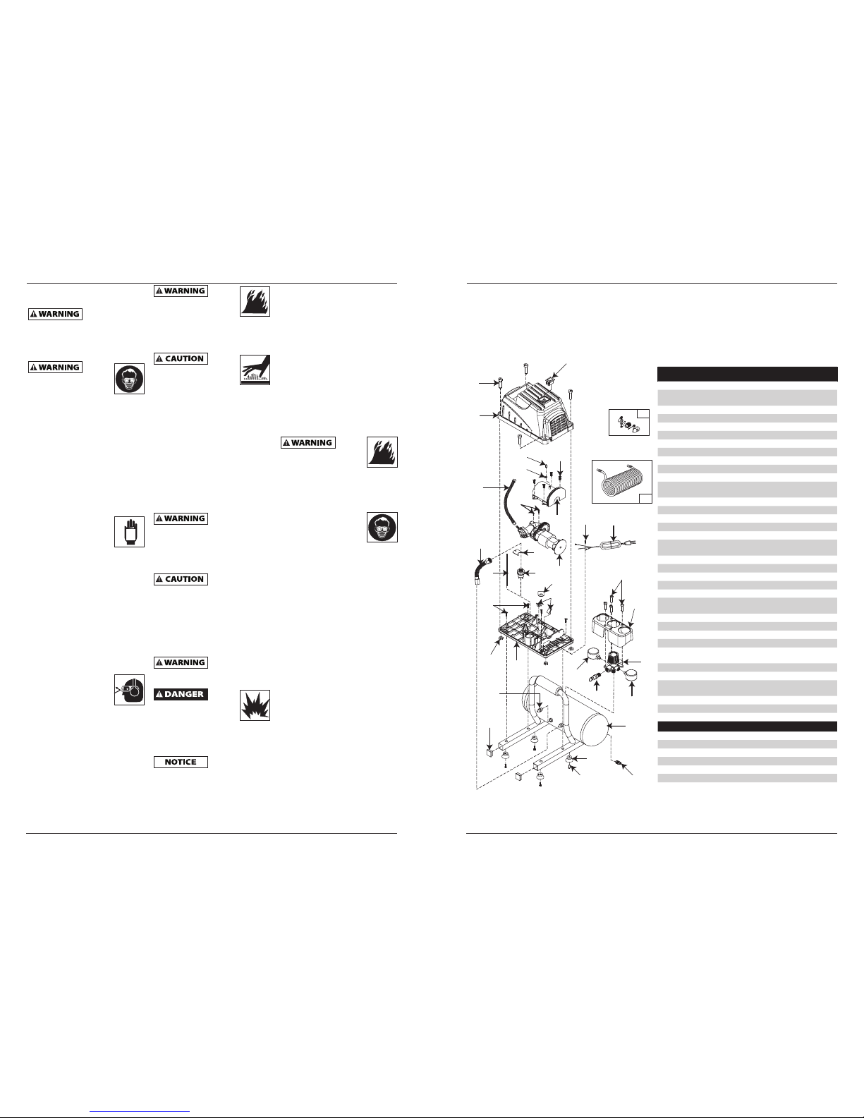
Lista de Repuestos
No. de
Ref. Descripción
Número del
Repuesto Ctd.
1 Tapa FP209536AV 1
2 Interruptor de encendido/
apagado FP204824AV 1
3 Tornillo
▲
4
4 Cubierta del múltiple
▲
1
5 Regulador
▲
1
6 Manómetro del regulador FP209528AV 1
7 Manómetro del tanque FP209821AV 1
8 Válvula de seguridad V-215104AV 1
9 Aislador del motor
■
2
10 Interruptor de presión FP209538AV 1
11 Valvula de chequeo FP209532AV 1
12 Cord No disponible No
disponible ón eléctrico
FP209534AV 1
13 Tornillo de la cubierta
◆
4
14 Tuerca
◆
4
15 Válvula de drenaje D-1403 1
16 Patas de caucho
●
4
17 Perno de pata
●
4
18 Cable (interruptor de presión a
interruptor de corriente) FP209523AV 1
19 Ensamblaje de bomba/motor DC010001AV 1
20 Sujetador del cable FP202823AV 1
21 Tornillo
❋
1
22 Cubierta del motor
▼
1
23 Accesorios (solo modelo FP2098) FP204008AV 1
24 Manguera de retroceso de
7,62 m (solo modelo FP2098) MP268100AV 1
25 Base plástica
▼
1
26 Juego de tubo del Presostato FP209535AV 1
27 Tanque — 1
28 Tapa plástica — 4
29 Tornillo autorroscante con
arandela
◆
2
30 Tornillo de la cubierta del motor
◆
4
31 Tornillo de base
◆
4
32 Soporte del interruptor de
presión — 1
33 Tornillo de descarga a tierra
❋
1
34 Relevo de tensión — 1
35 Tubo de escape FP202839AV 1
JUEGOS DE REPUSTOS Y ACCESORIOS
▲
Ensamblaje del distribuidor FP209820AV
■
Kit de aislador (Incluye #4) FP209037AV
●
Kit de pés FP209522AV
◆
Juego de sujetadores FP209041AV
▼
Juego de la cubierta del motor FP209038AV
❋
Artículo estándar de ferretería
— No disponible
Page 3

Manual de Instrucciones de Operación y Lista de Piezas
22 Sp
Serie DC0100, FP2098
Guía de Diagnóstico de Averías
Problema Posible(s) Causa(s) Acción a Tomar
El compresor no
funciona
1. El interruptor está en la posición
OFF (apagado)
1. Asegúrese de que el compresor esté enchufado y que
el interruptor esté en la posición ON (encendido)
2. No hay corriente eléctrica en el
tomacorriente de la pared
2. Revise el disyuntor o fusible en el panel de
electricidad.
3. El compresor alcanzó la presión de
corte automático
3. Libere aire del tanque hasta que el compresor se
reinicie automáticamente.
4. Motor recalentado 4. Deje que el compresor se enfríe durante
aproximadamente 30 minutos para que el interruptor
térmico de sobrecarga vuelva a su posición normal.
Asegúrese de que el compresor esté funcionando en
un área limpia y bien ventilada donde la temperatura
no exceda los 100ºF.
5. Conexiones eléctricas sueltas 5. Verifique todas las conexiones eléctricas
6. Interruptor de ON/OFF defectuoso 6. Reemplace el interruptor ON / OFF
7. Interruptor de presión defectuoso 7. Cambie el interruptor de presión
8. Motor defectuoso 8. Reemplace el ensamble de la bomba/motor
El protector térmico
de sobrecarga
detiene el
funcionamiento
reiteradamente
1. Falta de ventilación adecuada/
temperatura ambiente demasiado
alta
1. Mueva el compresor a un área limpia y bien ventilada
donde la temperatura no exceda los 100ºF.
2. Uso excesivo de aire, el compresor
es demasiado pequeño
2. Disminuya el uso o compre una unidad que ofrezca
una entrega de aire mayor (SCFM)
La presión del
tanque disminuye
cuando se apaga el
compresor
1. La válvula de drenaje del tanque
está abierta
1. Cierre la válvula de drenaje del tanque
2. Conexiones flojas (accesorios,
tubería, manguera de aire,
cualquier conexión, etc.)
2. Revise todas las conexiones con una solución de agua
y jabón. Si se detecta una fuga, apriete. O quite la
conexión y aplique cinta para tuberías a las rocas y
vuelva a armar.
No desensamble la válvula de
retención con aire en el tanque;
purgue el tanque.
3. Fugas del tanque 3. Revise todo el tanque en busca de fugas con una
solución de agua y jabón.
El compresor trabaja
sin parar/la salida de
aire es inferior a lo
normal
1. Uso excesivo de aire, el compresor
es demasiado pequeño
1. Disminuya el uso o compre una unidad que ofrezca
una entrega de aire mayor (SCFM)
2. La válvula de drenaje del tanque
está abierta
2. Cierre la válvula de drenaje del tanque
3. Conexiones flojas (accesorios,
tubería, manguera de aire,
cualquier conexión, etc.)
3. Revise todas las conexiones con una solución de agua
y jabón. Si se detecta una fuga, apriete. O quite la
conexión y aplique cinta para tuberías a las rocas y
vuelva a armar.
4. La bomba se ha desgastado 4. Reemplace el ensamble de la bomba/motor
Exceso de humedad
en el aire de
descarga
1. Demasiada agua en el tanque 1. Drene el tanque, incline el tanque para eliminar la
humedad
2. Humedad elevada 2. Llévelo a un área menos húmeda, utilice un filtro de
aire de línea
El compresor
funciona en forma
continua y la válvula
de seguridad se abre
cuando aumenta la
presión
1. Presostato defectuoso 1. Cambie el presostato
2. Válvula de seguridad defectuosa 2. Cambie la válvula de retención con un repuesto
original
DC0100, FP2098 Series
3
www.campbellhausfeld.com
Operating Instructions and Parts List
Introduction
R efer to Figure 3 to locate the
following items.
ON / OFF Switch ( I / O ) - Push
switch to the ON ( I ) position to turn
compressor on. Push switch to the OFF
( O ) position to turn compressor off.
This switch should be in the OFF ( O )
position when connecting /
disconnecting power cord from
electrical outlet or when changing
tools.
Pressure Switch (located
internally)- When the compressor
is turned ON, this switch will shut
compressor off automatically when
tank pressure reaches maximum shutoff / cut-out pressure. If compressor
remains on and air is depleted from
tank, this switch will allow compressor
to automatically restart at the restart /
cut-in pressure.
Drain Valve - This valve is located on
the bottom of the tank. Use this valve
to drain moisture from the tank daily
to reduce the risk of corrosion.
Motor Reset - (not shown, located
inside motor). Designed to keep the
motor from overheating. The motor
has a self-hold protector. If the unit
is over worked, a thermal limiter will
shut unit off. If it happens, switch the
unit to the OFF position and unplug
the unit. Wait 30 minutes, plug the
unit in and switch the unit to the
ON position again to resume work.
This compressor is
equipped with an
overload protector which will shut off
motor if it becomes overloaded.
If the overload
protector is
actuated, the motor must be allowed
to cool down for approximately 30
minutes before it will reset.
Regulator - The regulator controls
the amount of air pressure released at
the hose outlet. Turning the regulator
knob clockwise (to the right) will
increase air pressure at the outlet.
Turning the knob counter-clockwise
(to the left) will lower air pressure to
the outlet. Turning knob fully counterclockwise will shut off flow of air
completely.
Pressure Gauges - There are two
gauges located next to the regulator.
These gauges read air pressure in
pounds per square inch (psi) The larger
gauge shows pressure at the outlet.
Make sure this gauge reads ZERO
(by adjusting the regulator) BEFORE
changing air tools or disconnecting
hose from outlet. The small gauge
shows pressure in the tank indicating
compressor is building pressure
properly.
ASME Safety Valve - This valve
automatically releases air if the tank
pressure exceeds the preset maximum.
Handle - Designed to move the
compressor.
Figure 2
Figure 1
Figure 3
Regulator
Regulator
Gauge
Tank Gauge
Air Outlet
Handle
Handle
Regulator
Tank Drain Valve
ASME Safety Valve
ON / OFF
Switch
Air
Outlet
Page 4
Operating Instructions and Parts List
4
www.campbellhausfeld.com
DC0100, FP2098 Series
Installation
LOCATION
It is extremely important to use the
compressor in a clean, well ventilated
area where the surrounding air
temperature will not be more than
100°F.
A minimum clearance of 18 inches
between the compressor and a wall
is required because objects could
obstruct air flow.
Do not locate the
compressor
air inlet near steam, paint spray,
sandblast areas or any other source
of contamination. This debris will
damage the motor.
GROUNDING INSTRUCTIONS
1. This product is for use on a
nominal 120 volt circuit and has a
grounding plug that looks like the
plug illustrated in Figure 4. Make
sure the product is connected
to an outlet having the same
confi guration as the plug. This
product must be grounded. In
the event of an electrical short
circuit, grounding reduces risk of
electrical shock by providing an
escape wire for electric current.
This product is equipped with a
cord having a grounding wire
with an appropriate grounding
plug. Plug must be plugged into
an outlet that is properly installed
and grounded in accordance with
all local codes and ordinances.
Improper
use of
grounding plug can result in
a possible risk of electrical
shock!
Do not use a
grounding adapter
with this product!
2. If repair or replacement of cord or
plug is necessary, do not connect
grounding wire to either fl at blade
terminal. The wire with insulation
having an external surface that
is green (with or without yellow
stripes) is the grounding wire.
Never connect
green (or green
and yellow) wire to a live terminal.
3. Check with a qualifi ed electrician
or serviceman if grounding
instructions are not completely
understood, or if in doubt as
to whether product is properly
grounded. Do not modify plug
provided; if it will not fi t outlet,
have proper outlet installed by a
qualifi ed electrician.
Overheating, short
circuiting and fi re
damage will result from inadequate
wiring.
LUBRICATION
This is an oilless product and DOES
NOT require lubrication to operate.
Pre-Operation
BEFORE FIRST START-UP
BREAK-IN PROCEDURE
(Complete this procedure before
using compressor for the first time.
Once completed, it is not necessary to
repeat.)
1. Turn regulator knob fully clockwise
(to the right) to open air fl ow.
2. Do not attach a hose or any other
fi tting to the compressor.
3. Turn ON / OFF switch to OFF
position.
4. Plug in power cord.
5. Turn ON / OFF switch to ON
position and run compressor for 30
minutes.
6. Turn ON / OFF switch to OFF
position.
7. Unplug power cord.
The compressor is now ready for use.
BEFORE EACH START-UP
OPERATING PROCEDURE
1. Turn regulator knob fully
counterclockwise (to the left) to
close air fl ow.
2. Connect air hose to outlet of
regulator.
3. Turn ON / OFF switch to OFF
position.
4. Plug in power cord.
5. Turn ON / OFF switch to ON
position and let compressor run
until it reaches automatic shutoff
pressure.
6. Attach tire chuck or tool to end of
hose.
7. Turn regulator knob clockwise (to
the right) to desired pressure of
tool being used.
Operation
START-UP
Do not attach air
tools to open end
of the hose until start-up is completed
and the unit checks OK.
ON / OFF CYCLING OF COMPRESSOR
In the ON / AUTO position, the
compressor pumps air into the tank.
When a shut-off (preset “cut-out”)
pressure is reached, the compressor
automatically shuts off.
If the compressor is left in the
ON / AUTO position and air is depleted
from the tank by use of a tire chuck,
tool, etc., the compressor will restart
automatically at its preset “cut-in”
pressure. When a tool is being used
continuously, the compressor will cycle
on and off automatically.
In the OFF position, the pressure
switch cannot function and the
compressor will not operate. Make
sure switch is in OFF position when
connecting or disconnecting power
cord from electrical outlet.
PRESSURE GAUGES
Gauge attached to regulator indicates
air pressure going to hose (and any
tool attached to end of hose).
Gauge attached to pressure switch
indicates air pressure in tank.
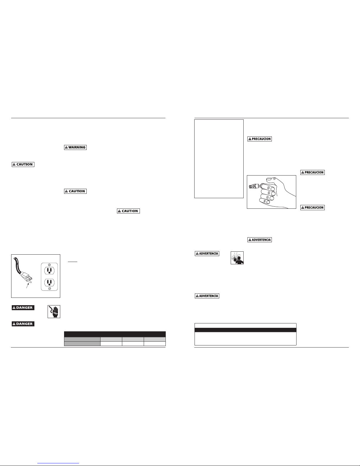
TEST
RESET
Figure 4 - Grounding Method
Grounded
Outlet
Grounding
Pin
Minimum Gauge of Extension Cords
Length of Cord 25 feet 50 feet 100 feet
Gauge 14 12 10
Serie DC0100, FP2098
21 Sp
Manual de Instrucciones de Operación y Lista de Piezas
Funcionamiento
(Continuación)
MANÓMETROS
El manómetro conectado al regulador
indica la presión de aire que pasa
por la manguera (y por cualquier
herramienta conectada al extremo de
la manguera).
El manómetro conectado al
interruptor de presión indica la
presión de aire en el tanque.
Mantenimiento
Desconecte el cordón
eléctrico y amárrelo; después
libere toda la presión del
sistema antes de tratar de instalarlo,
darle servicio o darle cualquier tipo de
mantenimiento.
Este compresor se debe chequear
con frecuencia para ver si tiene algún
tipo de problemas y le debe dar el
siguiente mantenimiento antes de
cada uso.
Se debe
reemplazar la
válvula de seguridad si no se puede
accionar o si tiene una fuga de aire
después de liberar el anillo.
1. Apague el compresor y libere la
presión del sistema. (Para liberar la
presión del sistema, tire del anillo
de la válvula de seguridad ASME.
Desvíe el aire cubriendo la válvula
con una mano mientras tira del
anillo con la otra mano.) Tire del
anillo hasta vaciar el tanque.
Cuando se abra
la válvula de
seguridad con presión en el tanque, se
liberará una gran cantidad de aire que
se mueve a gran velocidad. Use gafas
de seguridad Z87.1 aprobadas por
ANSI.
2. Drene la humedad del tanque
abriendo la válvula de drenaje
debajo del tanque. Incline el
tanque para eliminar toda la
humedad.
3. Limpie el polvo y la suciedad del
tanque, las líneas de aire y la
cubierta de la bomba, mientras
el compresor continúa apagado
(OFF).
VALVULA DE SEGURIDAD ASME
¡Nunca
desconecte o
trate de ajustar la válvula de
seguridad ASME!
Revise la válvula de seguridad
siguiendo los siguientes pasos:
1. Enchufe el compresor y hágalo
funcionar hasta que se alcance
la presión de corte (consulte
Funcionamiento).
2. Usando gafas de protección,
tire del anillo de la válvula de
seguridad para liberar la presión
del tanque del compresor. Use su
otra mano para desviar el aire que
se mueve a gran velocidad y evitar
que le dé en el rostro.
3. Esta válvula de seguridad debería
cerrarse automáticamente a
2,76 bar - 3,45 bar. Si la válvula
de seguridad no deja salir aire
cuando tira del anillo o si no se
cierra automáticamente, DEBE ser
reemplazada.
HUMEDAD EN EL AIRE
COMPRIMIDO
La humedad que se acumula en
el aire comprimido se convierte
en gotas a medida que sale de
la bomba. Cuando el nivel de
humedad es muy alto o cuando
el compresor ha estado en uso
continuo por mucho tiempo, esta
humedad se acumulará en el
tanque. Cuando esté pintando o
rociando arena, la humedad saldrá
del tanque mezclada con el material
que esté rociando.
IMPORTANTE: Esta condensación
ocasionará manchas en la pintura,
especialmente cuando esté
pintando con pinturas que no sean
a base de agua. Si está rociando
arena, la humedad hará que la
arena se aglutine y obstruya la
pistola.
DRENAJE DEL TANQUE
Apague el compresor y libere toda
la presión, después: Abra la llave de
drenaje, ubicada debajo del tanque,
para drenarle toda la humedad.
LIMPIEZA
APAGUE la unidad y limpie la tapa del
cabezal, el tanque y las líneas de aire.
LUBRICACION
Este compresor no requiere
lubricación.
SECCIÓN DEL PROTECTOR DE LA
SOBRECARGA
Este compresor
está equipado con
un protector manual contra sobrecarga
que apagará el motor cuando éste se
sobrecargado.
Si el protector apaga el motor con
mucha frecuencia puede ser por lo
siguiente:
1. Voltaje bajo.
2. La ventilación es inadecuada.
Si se activa el
protector de
sobrecarga, se debe dejar enfriar el
motor durante 30 minutos antes de
reiniciarlo manualmente.
CONCLUSIÓN DEL TRABAJO /
ALMACENAJE
1. Coloque el interruptor de ON / OFF
en la posición OFF (apagado).
2. Desenchufe el cordón del
tomacorrientes de pared y
envuélvalo alrededor del mango
para prevenir daños cuando no se
use.
3. Con las gafas de seguridad puestas,
descargue el aire del tanque
halando el anillo de la válvula de
seguridad. Use su otra mano para
desviar el aire que se mueve a gran
velocidad y evitar que le dé en el
rostro.
4. Drene el tanque de la
condensación abriendo la válvula
de drenaje al fondo del tanque.
Cuando drene el tanque, la presión
debe estar por debajo de 0,69 bar.
5. Debe desconectar la manguera
del compresor y colgarla con los
extremos hacia abajo para que
toda humedad se drene.
6. El compresor y la manguera deben
guardarse en un lugar fresco y
seco.
ASSISTENCIA TÉCNICA
Para recibir información sobre el
funcionamiento o reparación de la
unidad, sírvase llamar al
1-800-543-6400 (en EUA).
MANTENIMIENTO
SERVICIO NECESARIO DIARIAMENTE SEMANALMENTE MENSUALMENTE
Drene el Tanque
●
Chequée la Válvula de
Seguridad
●
Limpie la unidad
●
Figure 5
Page 5

Manual de Instrucciones de Operación y Lista de Piezas
20 Sp
Serie DC0100, FP2098
Instalación
COLOCACIÓN
Es extremadamente importante
instalar el compresor en un área
limpia, seca y bien ventilada. El
compresor debe estar ubicado sobre
una superficie firme y nivelada donde
la temperatura del aire circunstante no
sobrepase los 38°C (100°F).
Se requiere un espacio mínimo de 45,7
cm (18 pulgadas) entre el compresor y
la pared, ya que los objectos podrían
obstruir el paso de aire.
No coloque la
entrada de aire
del compresor cerca de áreas con
vapor, vapores de pintura, chorros
de arena o cualquier otra fuente
de contaminación. Los desperdicios
dañarán el motor.
CONEXION A TIERRA
1. Este producto está diseñado para
circuitos nominales de 120 voltios
y tiene un enchufe para conexión
a tierra similar al de la Figura 4.
Cerciórese de conectarlo a un
tomacorrientes cuya confi guración
sea similar a la del enchufe. Este
producto se debe conectar a
tierra. En caso de que ocurra un
cortocircuito, ésto evitaría el riesgo
de choque eléctrico al ofrecerle
un cable de desvío a la corriente
eléctrica. Este producto tiene un
cordón con un alambre y terminal
de conexión a tierra. Debe
conectarlo a un tomacorrientes
que esté instalado adecuadamente
según los códigos y ordenanzas
locales.
El uso
inadecuado del enchufe
con conexión a tierra
podría ocasionarle choques
eléctricos.
No use un
adaptador para
conexión a tierra con este producto.
2. Si necesita reparar o reemplazar
el cordón o el enchufe, no conecte
el cable de conexión a tierra a
ninguno de los terminales planos.
El alambre cuya superfi cie externa
del aislante es verde, con o sin
rayas amarillas, es el cable de
conexión a tierra.
Nunca conecte
los cables verdes
o verde con rayas amarillas, a un
terminal con tensión.
3. Consúltele a un electricista
califi cado o a un técnico
de reparación, en caso de
que no comprenda bien las
instrucciones o si tiene dudas
de que esté conectado a tierra
adecuadamente. No modifi que
el enchufe, si éste no entra en el
tomacorrientes, mande a instalar
un tomacorrientes adecuado con
un electricista califi cado.
Un cableado
inadecuado provocará daños por
sobrecalentamiento, cortocircuitos
e incendio.
LUBRICACION
Este es un aparato sin aceite y NO
REQUIERE lubricación para su
funcionamiento.
Pre-Funcionamiento
ANTES DE ARRANCARLO POR
PRIMERA VEZ - PROCEDIMIENTO
DE ABLANDE
(Complete este procedimiento antes
de usar el compresor por primera vez.
Una vez completado, no es necesario
repetirlo.)
1. Gire la perilla del regulador
totalmente hacia la derecha para
abrir el fl ujo de aire.
2. No conecte una manguera ni
ningún otro accesorio al salida de
aire del compresor.
3. Coloque el interruptor de
encendido/apagado en la posición
OFF (apagado).
4. Enchufe el cable de corriente.
5. Coloque el interruptor de
encendido/apagado en la posición
ON (encendido). Deje que el
compresor funcione durante 30
minutos.
6. Coloque el interruptor de
encendido/apagado en la posición
OFF (apagado).
7. Desenchufe el cable de corriente.
Ahora el compresor está listo para ser
usado.
ANTES DE INICIAR CADA
PROCEDIMIENTO DE ENCENDIDO
1. Gire la perilla del regulador
totalmente hacia la izquierda.
2. Conecte la manguera de aire a la
salida del regulador.
3. Coloque el interruptor de
encendido/apagado en la posición
OFF (apagado).
4. Enchufe el cable de corriente.
5. Gire el interruptor de encendido/
apagado a la posición ON
(encendido) y deje que el
compresor funcione hasta que
alcance la presión de apagado
automático.
6. Conecte la boquilla para infl ar
neumáticos u otra herramienta al
extremo de la manguera.
7. Gire la perilla del regulador
hacia la derecha hasta la presión
deseada para la herramienta que
esté usando.
Funcionamiento
ENCENDIDO
No conecte
ninguna
herramienta al extremo de la
manguera hasta que haya terminado
el proceso de preparación para el uso
y haya verifi cado que la unidad esté
lista para funcionar.
CICLO DE ENCENDIDO/APAGADO
DEL COMPRESOR
En la posición ON/AUTO (encendido/
automático), el compresor bombea
aire dentro el tanque. Cuando se
alcanza la presión de apagado
(“corte” preestablecido), el compresor
se apaga automáticamente.
Si se deja el compresor en la posición
ON/AUTO (encendido/automático)
y el aire sale del tanque al usar una
boquilla para infl ar neumáticos,
una herramienta, etc., el compresor
se reiniciará automáticamente a su
presión de “corte” preestablecida.
Cuando se use una herramienta
en forma continua, el compresor
cumplirá un ciclo de encendido y
apagado en forma automática.
En la posición OFF (apagado), el
interruptor de presión no puede
funcionar y el compresor no se pondrá
en funcionamiento. Asegúrese de que
el interruptor esté en la posición OFF
cuando conecte o desconecte el cable
de corriente del tomacorriente.
TEST
RESET
Figura 4 - Méthode de mise à
la terre
Tomacorrientes
conectado a tierra
Terminal de
conexión a tierra
Calibre mínimo de los cables de extensión
Longitud del cordón 7,62 m 15,24 m 30,48 m
Calibre 14 12 10
DC0100, FP2098 Series
5
www.campbellhausfeld.com
Operating Instructions and Parts List
Maintenance
Disconnect, tag and lock out
power source, then release
all pressure from the system
before attempting to install, service,
relocate or perform any maintenance.
Check compressor often for any visible
problems and follow maintenance
procedures each time compressor is
used.
Safety valve must
be replaced if it
cannot be actuated or it leaks air after
ring is released.
1. Turn compressor off and release
pressure from system. (To release
pressure from system, pull ring
on ASME safety valve. Deflect
escaping air by shielding valve with
one hand as you pull ring with
other hand.) Pull ring until tank is
empty.
A large amount of
fast moving air
will be released when the safety valve
is opened with pressure in the tank.
Wear ANSI approved Z87.1 safety
glasses.
2. Drain moisture from tank by
opening drain valve underneath
tank. Tilt tank to remove all
moisture.
3. Clean dust and dirt from tank,
air lines and pump cover while
compressor is still OFF.
ASME SAFETY VALVE
Do not remove or
attempt to adjust
the safety valve!
Check the safety valve by performing
the following steps:
1. Plug the compressor in and run
until shut off pressure is reached.
2. Wearing safety glasses, pull the
ring on the safety valve to release
pressure from compressor tank.
Use your other hand to defl ect
fast-moving air from being
directed toward your face.
3. The safety valve should
automatically close at
approximately 40 psi - 50 psi. If
the safety valve does not allow
air to be released when you pull
on the ring, or if it does not close
automatically, it MUST be replaced.
DRAIN TANK
With compressor shut off and pressure
released, drain moisture from tank by
opening drain valve underneath tank.
CLEANING
Turn power OFF and clean dust and
dirt from pump cover, tank, and air
lines.
LUBRICATION.
This is an oilless type compressor
requiring no lubrication.
MOISTURE IN COMPRESSED AIR
Moisture in compressed air will
form into droplets as it comes
from an air compressor pump.
When humidity is high or when
a compressor is in continuous use
for an extended period of time,
this moisture will collect in the
tank. When using a paint spray or
sandblast gun, this water will be
carried from the tank through the
hose, and out of the gun as droplets
mixed with the spray material.
IMPORTANT: This condensation
will cause water spots in a paint
job, especially when spraying
other than water based paints. If
sandblasting, it will cause the sand
to cake and clog the gun, rendering
it ineffective.
A fi lter in the air line, located as
near to the gun as possible, will
help eliminate this moisture.
Figure 5
OVERLOAD PROTECTOR
This compressor
is equipped with
a thermal overload protector which
will shut off motor if it becomes
overloaded.
If overload protector shuts motor OFF
frequently, look for the following
causes.
1. Low voltage.
2. Lack of proper ventilation.
If the overload
protector is
actuated, the motor must be allowed
to cool down for 30 minutes before
manual resetting.
END OF OPERATION/STORAGE
1. Turn ON / OFF switch to the OFF
position.
2. Unplug power cord from wall
outlet and wrap around handle
area to prevent damage when not
in use.
3. Wearing safety glasses drain tank
of air by pulling the ring on the
safety valve. Use other hand to
defl ect fast moving air from being
directed toward your face.
4. Drain tank of condensation by
opening drain valve on bottom
of tank. Tank pressure should be
below 10 psi when draining tank.
5. Air hose should be disconnected
from compressor and hung open
ends down to allow any moisture
to drain.
6. Compressor and hose should be
stored in a cool, dry place.
TECHNICAL SERVICE
For information regarding the
operation or repair of this product,
please call 1-800-543-6400.
MAINTENANCE SCHEDULE
OPERATION DAILY WEEKLY MONTHLY
DRAIN TANK
●
CHECK SAFETY VALVE
●
CLEAN UNIT
●
Page 6

Operating Instructions and Parts List
6
www.campbellhausfeld.com
DC0100, FP2098 Series
Troubleshooting Chart
Symptom Possible Cause(s) Corrective Action
Compressor will not
run
1. Switch in OFF position 1. Make sure compressor is plugged in and switch is ON
2. No electrical power at wall outlet 2. Check circuit breaker or fuse at electrical panel.
3. Compressor has reached automatic
shut-off pressure
3. Release air from tank until compressor restarts
automatically
4. Motor overheated 4. Allow compressor to cool for approximately 30
minutes so thermal overload switch will reset. Make
sure compressor is run in a clean, well-ventilated area
where temperature will not exceed 100°F.
5. Loose electrical connection 5. Check all electrical connections
6. ON / OFF switch bad 6. Replace ON / OFF switch
7. Pressure switch bad 7. Replace pressure switch
8. Defective motor 8. Replace pump / motor assembly
Thermal overload
protector cuts out
repeatedly
1. Lack of proper ventilation/room
temperature too high
1. Move compressor to a clean,well ventilated area
where temperature will not exceed 100°F.
2. Excessive air usage, compressor too
small
2. Decrease usage or purchase unit with higher air
delivery (SCFM)
Tank pressure drops
when compressor
shuts off
1. Open tank drain valve 1. Close tank drain valve
2. Loose connections (fittings, tubing,
air hose, any connections, etc.)
2. Check all connections with soap and water solution.
If a leak is detected, tighten. Or remove fitting and
apply pipe tape to threads and reassemble.
Do not disassemble check valve with
air pressure in tank; bleed tank.
3. Tank leaks 3. Check entire tank for leaks with soap and water
solution
Compressor runs
continuously / air
output lower than
normal
1. Excessive air usage, compressor too
small
1. Decrease usage or purchase unit with higher air
delivery (SCFM)
2. Open tank drain valve 2. Close tank drain valve
3. Loose connections (fittings, tubing,
air hose, any connections, etc.)
3. Check all connections with soap and water solution.
If a leak is detected, tighten. Or remove fitting and
apply pipe tape to threads and reassemble.
4. Pump wore out 4. Replace pump / motor assembly
Excessive moisture in
discharge air
1. Excessive water in tank 1. Drain tank, tilt tank to remove moisture
2. High humidity 2. Move to area of less humidity; use air line filter
Safety valve pops
open
1. Defective pressure switch 1. Replace pressure switch
2. Defective safety valve 2. Replace safety valve with genuine replacement part
Serie DC0100, FP2098
19 Sp
Manual de Instrucciones de Operación y Lista de Piezas
Introducción
Vea la Figura 3.
Interruptor ON/OFF ( I / O ) - Ponga
el interruptor en la posición ON ( I )
para encender el compresor. Ponga el
interruptor en la posición OFF
( O ) para apagar el compresor. El
interruptor debe colocarse en la
posición OFF ( O ) para conectar
o desconectar el cordón eléctrico
del tomacorrientes o para cambiar
herramientas.
Regulador - El regulador controla la
cantidad de presión de aire expulsada
por la manguera. Al girar la perilla del
regulador en sentido horario (hacia la
derecha) la presión de aire a la salida
aumenta. Al girar la perilla en sentido
antihorario (hacia la izquierda) la
presión de aire a la salida disminuye.
Al girar la perilla completamente en
sentido antihorario, el suministro de
aire se cierra completamente.
Reinicio del motor - (no se muestra,
ubicado dentro del motor). Diseñado
para evitar que el motor se recaliente.
El motor tiene un protector de
autorretención. Si la unidad está sobre
exigida, un limitador térmico apagará
la unidad. Si esto sucede, coloque la
unida en la posición de apagado (OFF)
y desenchúfela. Espere 30 minutos,
enchufe la unidad y coloque la
unidad nuevamente en la posición de
encendido (ON) para continuar con el
trabajo.
Este compresor
está equipado
con un protector de sobrecarga que
apagará el motor si éste se sobrecarga.
Si se activa el
protector de
sobrecarga, se debe dejar enfriar el
motor durante aproximadamente
30 minutos antes de que se reinicie.
Manómetros - Hay dos tipos
de manómetros ubicados cerca
del regulador. Estos manómetros
indican la presión de aire en libras
por pulgada cuadrada (bar). El
manómetro más grande indica la
presión a la salida. Asegúrese de
que este manómetro indique CERO
(ajustando el regulador) ANTES de
cambiar herramientas neumáticas o
desconectar la manguera de la salida.
El manómetro pequeño mide la
presión del tanque para indicar que el
compresor está aumentando la presión
adecuadamente.
Válvula de seguridad ASME - Esta
válvula automáticamente libera el aire
si la presión del tanque excede el valor
máximo fijado de fábrica.
Mango - Diseñado para mover el
compresor.
Llave de drenaje - Esta válvula está
ubicada debajo del tanque. Úsela
para drenar la humedad del tanque
diariamente, para evitar que el tanque
se oxide.
Figura 1
Figura 2
Figura 3
Regulador
Manómetro del
regulador
Manómetro del tanque
Sortie d’airet
Mango
Mango
Regulador
Válvula de drenaje del tanque
Válvula de seguridad ASME
Interruptor de
encendido/apagado
Sortie
d’airet
Page 7

Manual de Instrucciones de Operación y Lista de Piezas
18 Sp
Serie DC0100, FP2098
Informaciones Generales de
Seguridad
PROPOSICIÓN 65 DE CALIFORNIA
Este producto,
o su cable de
corriente pueden contener químicos,
incluido plomo, que es conocido por
el Estado de California como causante
de cáncer y defectos de nacimiento u
otros daños reproductivos. Lávese las
manos después de manipularlo.
Cuando corta lija, taladra
o pule materiales como
por ejemplo madera,
pintura, metal, hormigón, cemento,
u otro tipo de mampostería se puede
producir polvo. Con frecuencia este
polvo contiene productos químicos
que se conocen como causantes de
cáncer, defectos congénitos u otros
daños reproductivos. Use equipo de
protección.
GENERALES SEGURIDAD
Como el compresor de aire y otros
componentes usados (bomba de
material, pistolas pulverizadoras,
filtros, lubricadores, mangueras, etc.)
intengran un sistema de alta presión,
en todo momento deberá seguir las
siguientes medidas de seguridad:
1. Lea con cuidado todos
los manuales incluídos
con este producto.
Familiarícese con los
controles y el uso
adecuado del equipo.
2. Siga todos los códigos de seguridad
laboral y electricidad establecidos
en su país, por ejemplo, los de la
NEC y OSHA en EUA.
3. Sólo personas bien familiarizadas
con estas medidas de seguridad
deben utilizar el compresor.
4. Mantenga a los visitantes alejados
y NUNCA permita la presencia de
niños en el área de trabajo.
5. Use anteojos de
seguridad y protéjase
los oídos para operar la
unidad.
6. No se encarame sobre la
unidad ni la use para sostenerse.
7. Antes de cada uso, revise el
sistema de aire comprimido y los
componentes eléctricos para ver si
están dañados, deteriorados o hay
fugas. Antes de usarlo cerciórese de
reemplazar las piezas defectuosas.
8. Chequée con frecuancia todas la
conecciones y cerciórese de que
estén bien apretadas.
Los
motores, equipos eléctricos
y controles, pueden
ocasionar arcos eléctricos
que se encenderían con gases o
vapores infl amables. Nunca utilice o
repare el compresor cerca de gases o
vapores infl amables. Nunca almacene
líquidos o gases infl amables cerca del
compresor.
Nunca
opere el
compresor sin las tapas de
protección. Esta unidad se
puede encender
automáticamente sin previo aviso. El
contacto con las piezas en movimiento
le podría ocasionar heridas o daños a
su propiedad.
9. Mantenga los dedos alejados
del compresor cuando esté
funcionando; las piezas en
movimiento o calientes le
ocasionarían heridas y/o
quemaduras.
10. Si el equipo comienza a vibrar
excesivamente, APAGUE la unidad
y chequéela inmediatamente
para determinar el problema.
Generalmente, la vibración se debe
a una falla.
11. Para reducir el peligro de
incendios, mantenga el exterior
del compresor limpio (sin aceite,
solvente o exceso de grasa).
DEBE instalarle
una válvula de
seguridad ASME que esté diseñada
para presiones máximas de 8,62 bar
en el tanque de este compresor. Esta
válvula debe estar diseñada para los
valores máximos de fl ujo y presión
para proteger los componentes bajo
presión contra el peligro de explosión.
Vea las
especifi caciones
del compresor en la calcomanía para
la presión máxima operativa. No opere
con el presostato o la válvula piloto
ajustados a presiones más elevadas de
la presión máx. operativa.
12. Nunca trate de ajustar la válvula
de seguridad ASME. Manténgala
limpia y evite que la acumulación
de pintura u otros desperdicios.
Nunca use
tuberías de
plástico (PVC) en sistemas de aire
comprimido. El compresor sin las
tapas de protección. El hacerlo podría
ocasionarle heridas o daños a su
propiedad.
¡Nunca
trate
de reparar o modifi car
el tanque! Al soldarlo,
taladarle orifi cios o
modifi carlo de cualquier otro modo
éste se debilitaría y podría romperse
o explotar. Siempre reemplace los
tanques desgastados, rotos o dañados.
Drene el tanque
diariamente.
13. Los tanques se oxidan debido
a la acumulación de humedad.
Cerciórese de drenar el tanque
con regularidad e inspéccionelo
periódicamente para ver si no
está en buenas condiciones, por
ejemplo si está oxidado.
14. Si expulsa aire rápidamente
podría levantar polvo o residuos
dañinos. Libere el aire lentamente
para drenar el tanque o liberar la
presión del compresor.
15. Uso de interior solamente.
16. Para reducir el riesgo de choque
eléctrico, no exponer a la lluvia.
Guarde bajo techo.
PRECAUCIONES PARA ROCIAR
Nunca
rocíe
materiales infl amables cerca
de llamas al descubierto
o fuentes de ignición,
incluyendo el compresor.
17. No fume mientras esté rociando
pintura, insecticidas u otras
substancias inflamables.
18. Use una máscara /
respirador cuando vaya a
rociar y siempre rocíe en
un área bien ventilada,
para evitar peligros de
salud e incendios.
19. Nunca rocíe la pintura y otros
materiales, directamente hacia el
compresor. Coloque el compresor
lo más lejos posible del área
de trabajo, para minimizar la
acumulación de residuos en el
compresor.
20. Al rociar o limpiar con solventes
o químicos tóxicos, siga las
instrucciones del fabricante de
dichos químicos.
MANUAL
DC0100, FP2098 Series
7
www.campbellhausfeld.com
Operating Instructions and Parts List
For replacement parts or technical assistance,
call 1-800-543-6400
Please provide following information:
- Model number
- Serial number (if any)
- Part description and number as shown in parts list
Address any correspondence to:
Campbell Hausfeld
Attn: Customer Service
100 Production Drive
Harrison, OH 45030
13
1
2
23
24
21
20
30
29
22
35
32
19
10
34
9
26
18
31
14
25
11
28
7
8
16
17
18
27
6
5
4
3
33
12
Replacement Parts List
Ref.
No. Description Part No. Qty.
1 Shroud assembly FP209536AV 1
2 On / Off switch FP204824AV 1
3 Screw
▲
4
4 Manifold Cover
▲
1
5 Regulator
▲
1
6 Regulator gauge FP209528AV 1
7 Tank gauge FP209821AV 1
8 Safety valve V-215104AV 1
9 Motor isolator
■
2
10 Pressure switch FP209538AV 1
11 Check valve FP209532AV 1
12 Power cord FP209534AV 1
13 Housing screw
◆
4
14 Nut
◆
4
15 Drain valve D-1403 1
16 Rubber foot
●
4
17 Foot bolt
●
4
18 Wire (pressure switch to
power switch) FP209523AV 1
19 Pump / motor assembly DC010001AV 1
20 Wire clip FP202823AV 1
21 Screw
❋
1
22 Motor cover
▼
1
23 5 piece Accessory kit (model
FP2098 only)
FP204008AV 1
24 25 foot Recoil house (model
FP2098 only)
MP268100AV 1
25 Plastic base
▼
1
26 Pressure switch tube assembly FP209535AV 1
27 Tank assembly — 1
28 Platic caps — 4
29 Washered head screw
◆
2
30 Motor housing Screw
◆
4
31 Base screw
◆
4
32 Pressure switch bracket — 1
33 Ground screw
❋
1
34 Strain relief — 1
35 Exhaust tube assembly FP202839AV 1
REPLACEMENT PARTS KITS
▲
Manifold assembly FP209820AV
■
Isolator kit (includes 4) FP209037AV
●
Feet kit FP209522AV
◆
Fastener kit FP209041AV
▼
Plastic base and motor cover FP209038AV
❋
Standard hardware item
— Not available
Page 8

Operating Instructions and Parts List
8
www.campbellhausfeld.com
DC0100, FP2098 Series
Limited Warranty
1. DURATION: From the date of purchase by the original purchaser as follows: One Year.
2. WHO GIVES THIS WARRANTY (WARRANTOR): Campbell Hausfeld a Marmon/Berkshire Hathaway Company, 100
Production Drive, Harrison, Ohio, 45030, Telephone: (800) 543-6400
3. WHO RECEIVES THIS WARRANTY (PURCHASER): The original purchaser (other than for purposes of resale) of the
Campbell Hausfeld compressor.
4. WHAT PRODUCTS ARE COVERED BY THIS WARRANTY: This Campbell Hausfeld air compressor.
5. WHAT IS COVERED UNDER THIS WARRANTY: Substantial defects due to material and workmanship with the
exceptions noted below.
6. WHAT IS NOT COVERED UNDER THIS WARRANTY:
A. Implied warranties, including those of merchantability and FITNESS FOR A PARTICULAR PURPOSE ARE LIMITED
FROM THE DATE OF ORIGINAL PURCHASE AS STATED IN THE DURATION. If this compressor is used for commercial,
industrial or rental purposes, the warranty will apply for ninety (90) days from the date of purchase. Some States
do not allow limitations on how long an implied warranty lasts, so the above limitations may not apply to you.
B. ANY INCIDENTAL, INDIRECT, OR CONSEQUENTIAL LOSS, DAMAGE, OR EXPENSE THAT MAY RESULT FROM ANY
DEFECT, FAILURE, OR MALFUNCTION OF THE CAMPBELL HAUSFELD PRODUCT. Some States do not allow the
exclusion or limitations of incidental or consequential damages, so the above limitation or exclusion may not apply
to you.
C. Any failure that results from an accident, purchaser’s abuse, neglect or failure to operate products in accordance
with instructions provided in the owner’s manual(s) supplied with compressor.
D. Pre-delivery service, e.g. assembly, oil or lubricants, and adjustment.
E. Items or service that are normally required to maintain the product, e.g. lubricants, filters and gaskets, etc.
F. Additional items not covered under this warranty:
1. Any component damaged in shipment or any failure caused by installing or operating unit under conditions
not in accordance with installation and operation guidelines or damaged by contact with tools or
surroundings.
2. Pump or valve failure caused by rain, excessive humidity, corrosive environments or other contaminants.
3. Cosmetic defects that do not interfere with compressor functionality.
4. Rusted tanks, including but not limited to rust due to improper drainage or corrosive environments.
5. Drain cocks.
6. Damage due to incorrect voltage or improper wiring.
7. Other items not listed but considered general wear parts.
8. Pressure switches, air governors and safety valves modified from factory settings.
9. Belts.
10. Ring wear or valve damage from inadequate filter maintenance.
7. RESPONSIBILITIES OF WARRANTOR UNDER THIS WARRANTY: Replace, at Warrantor’s option, compressor or
component which is defective, has malfunctioned and/or failed to conform within the duration of the specific
warranty period.
8. RESPONSIBILITIES OF PURCHASER UNDER THIS WARRANTY:
A. Provide dated proof of purchase and maintenance records.
B. Call Campbell Hausfeld (800-543-6400) to obtain your warranty service options. Freight costs must be borne by the
purchaser.
C. Use reasonable care in the operation and maintenance of the products as described in the owner’s manual(s).
9. WHEN WARRANTOR WILL PROVIDE REPLACEMENT UNDER THIS WARRANTY: Replacement will be scheduled according
to the availability of replacement compressor or parts.
This Limited Warranty applies in the U.S., Canada and Mexico only and gives you specific legal rights. You may also have
other rights which vary from State to State or country to country.
Por favor lea y guarde estas instrucciones. Léalas cuidadosamente antes de tratar de montar, instalar, operar o dar mantenimiento
al producto aquí descrito. Protéjase usted mismo y a los demás observando toda la información de seguridad. ¡El no cumplir con las
instrucciones puede ocasionar daños, tanto personales como a la propiedad! Guarde estas instrucciones para referencia en el futuro.
Ver la Garantía en página 24 para información importante sobre el uso comercial de este producto.
Manual de Instrucciones de Operación y Lista de Piezas Serie DC0100, FP2098
RECORDATORIO: ¡Guarde su comprobante de compra con fecha para fines de la garantía!
Adjúntela a este manual o archívela en lugar seguro.
IN626703AV 12/15© 2015 Campbell Hausfeld
A Marmon/Berkshire Hathaway Company
17 Sp
Descripción
Compresores sin aceite diseñados
para los aficionados al bricolaje,
con una variedad de trabajos
domésticos y automotores. Estas
unidades funcionan sin aceite El aire
comprimido que sale de esta unidad
contiene humedad. Instale un filtro
de humedad o un secador de aire si la
aplicación requiere aire seco.
Desempaque
Cuando desempaque la unidad,
inspecciónela cuidadosamente para
verificar si se han producido daños
durante el transporte. Asegúrese de
apretar todos los accesorios, pernos,
etc. que estén sueltos antes de poner
la unidad en servicio. En el caso de que
haya daño o partes que faltan, haga el
favor de llamar al 1-800-543-6400 para
obtener ayuda.
Se incluye una lista de los lugares en
donde se encuentran los centros de
servicio. Tenga a mano el número de
serie, el número del modelo y la lista
de partes (con las partes que faltan
marcadas con un círculo) antes de
llamar.
NE PAS RENVOYER
LE PRODUIT AU
MARCHAND!
No debe utilizar la
unidad si se ha
dañado durante el envío, manejo o
uso. Los daños podrían ocasionar una
explosión y ocasionarle heridas o
daños a su propiedad.
LEA Y SIGA TODAS LAS
INSTRUCCIONES
GUARDE ESTAS INSTRUCCIONES
NO LAS DESECHE
Medidas de Seguridad
Este manual contiene información
que es muy importante que sepa
y comprenda. Esta información
se la suministramos como medida
de SEGURIDAD y para EVITAR
PROBLEMAS CON EL EQUIPO. Debe
reconocer los siguientes símbolos.
Peligro indica
una situación
inminentemente peligrosa, que si no se
evita, dará como resultado la muerte o
lesiones graves.
Advertencia indica
una situación
potencialmente peligrosa, que si no se
evita, PODRÍA ocasionar la muerte o
lesiones graves.
Precaución indica
una situación
potencialmente peligrosa, que si no
se evita, PUEDE dar como resultado
lesiones leves o moderadas.
ALTO!
Aviso indica
una información
importante, que de no seguirla, le podría
ocasionar daños al equipo.
NOTA: Información que requiere
atención especial.
Compresores
Sin Aceite
Advertencia sobre
el aire respirable
Este compresor/cabezal no
viene listo de fábrica para
suministrarle aire respirable.
Antes de utilizarlos con este
fin, deberá instalarle un
sistema de seguridad y alarma
incorporado a la línea. Este
sistema adicional es necesario
para filtrar y purificar el aire
adecuadamente, para cumplir
con las especificaciones mínimas
sobre aire respirable de Grado
D descritas en la Especificación
de Productos G 7.1 - 1966 de la
Asociación de Aire Comprimido.
Igualmente, deberá cumplir los
requisitos establecidos por el
Artículo 29 CFR 1910. 134 de la
Organización norteamericana
OSHA y/o la Canadian Standards
Associations (CSA).
RENUNCIA A LAS GARANTIAS
Si el compresor se utiliza para
producir aire respirable SIN
haberle instalado el sistema
de seguridad y alarma, todas
la garantías se anularán
y la compañia Campbell
Hausfeld no asumirá NINGUNA
responsabilidad por pérdidas,
heridas personales o daños.
Registre en el espacio a
continuación el No. del Modelo,
el Número de Serie y la Fecha de
Compra ubicados en la base debajo
de la bomb.
No. del Modelo ___________________
No. de Serie ___________________
Fecha de Compra ____________
Guarde estos números para
referencia en el futuro.
¡REGISTRE SU PRODUCTO EN LÍNEA AHORA MISMO! http://www.chpower.net/reg
Page 9

Instructions d’Utilisation et Manual de Pièces
16 Fr
Série DC0100, FP2098
Garantie Limitée
1. DURÉE : À partir de la date d’achat par l’acheteur original comme suit : Un An.
2. GARANTIE ACCORDÉE PAR (GARANT) : Campbell Hausfeld a Marmon/Berkshire Hathaway Company, 100 Production
Drive, Harrison, Ohio, 45030, Téléphone : (800) 543-6400
3. BÉNÉFICIAIRE DE CETTE GARANTIE (ACHETEUR) : L’acheteur original (sauf en cas de revente) du produit Campbell
Hausfeld.
4. PRODUITS COUVERTS PAR CETTE GARANTIE : Ce compresseur d’air Campbell Hausfeld.
5. COUVERTURE DE LA PRÉSENTE GARANTIE : Défauts de matière et de fabrication considérables avec les exceptions
indiquées ci-dessous.
6. LA PRÉSENTE GARANTIE NE COUVRE PAS :
A. Les garanties implicites, y compris celles de commerciabilité et D’ADAPTATION À UNE FONCTION PARTICULIÈRE
SONT LIMITÉES À PARTIR DE LA DATE D’ACHAT INITIALE TELLE QU’INDIQUÉE DANS LA SECTION DURÉE. Si ce
compresseur d’air est utilisé pour une fonction commerciale, industrielle ou pour la location, la durée de la
garantie sera de quatre-vingt-dix (90) jours à compter de la date d’achat. Quelques Provinces (États) n’autorisent
pas de limitations de durée pour les garanties implicites. Les limitations précédentes peuvent donc ne pas
s’appliquer dans votre cas.
B. TOUT DOMMAGE, PERTE OU DÉPENSE FORTUIT OU INDIRECT POUVANT RÉSULTER DE TOUT DÉFAUT, PANNE OU
MAUVAIS FONCTIONNEMENT DU PRODUIT CAMPBELL HAUSFELD. Quelques Provinces (États) n’autorisent pas
l’exclusion ni la limitation des dommages fortuits ou indirects. La limitation ou l’exclusion précédente peut ne
donc pas s’appliquer.
C. Toute panne résultant d’un accident, d’une utilisation abusive, de la négligence ou d’une utilisation ne respectant
pas les instructions données dans le(s) manuel(s) accompagnant le produit.
D. Service avant livraison; le montage, l’huile ou les lubrifiants et les réglages par exemple.
E. Articles ou services qui sont exigés pour l’entretien normal du produit; lubrifiants, filtres et joints d’étanchéités par
exemples.
F. Articles supplémentaires qui ne sont pas couverts sous cette garantie :
1. Toutes pièces détachées endommagées pendant l’expédition, n’importe quelle panne causée par un montage
ou fonctionnement du modèle sous des conditions qui ne conforment pas aux directives de montage et de
fonctionnement ou dommage causée par le contact avec les outils ou les alentours.
2. La panne de la pompe ou de la soupape causée par la pluie, l’humidité excessive, un environnement corrosif ou
autres polluants.
3. Les défauts de forme qui n’ont pas d’effet sur le fonctionnement du compresseur.
4. Les réservoirs rouillés, y compris mais pas limités à la rouille causé par le vidange incorrect ou par un
environnement corrosif.
5. Robinets de vidange.
6. Dommage dû à la tension ou installation de fils incorrecte.
7. Autres articles pas indiqués mais considérés pièces à fatigue générales.
8. Manostats, régulateurs d’air et soupapes de sûreté qui ont étés modifiés d’après les réglages de l’usine.
9. Courroies
10. Usure de bagues causée par l’entretien de filtre insuffisant
7. RESPONSABILITÉS DU GARANT AUX TERMES DE CETTE GARANTIE : Réparer ou remplacer, au choix du Garant, les
produits ou composants défectueux, qui ont connu une défaillance et/ou qui ne sont pas conformes pendant la durée
précise de validité de la garantie.
8. RESPONSABILITÉS DE L’ACHETEUR AUX TERMES DE CETTE GARANTIE :
A. Fournir une preuve d’achat datée et un état d’entretien.
B. Appelez Campbell Hausfeld (800-543-6400) pour obtenir vos options de service sous garantie. Les frais de transport
sont la responsabilité de l’acheteur.
C. Utilisation et entretien du produit avec un soin raisonable, ainsi que le décri(vent)t le(s) manuel(s) d’utilisation.
9. LORSQUE LE GARANT FOURNIT LE REMPLACEMENT SOUS LA GARANTIE : Le remplacement se fera selon la
disponibilité des pièces ou du compresseur de rechange.
Cette Garantie Limitée s’applique aux É.-U., au Canada et au Mexique seulement et vous donne des droits juridiques
précis. L’acheteur peut également jouir d’autres droits qui varient d’une Province, d’un État ou d’un Pays à l’autre.
Veuillez lire et conserver ces instructions. Lire attentivement avant de commencer à assembler, installer, faire fonctionner ou entretenir
l'appareil décrit. Protégez-vous et les autres en observant toutes les informations sur la sécurité. Négliger d'appliquer ces instructions peut
résulter en des blessures corporelles et/ou en des dommages matériels ! Conserver ces instructions pour références ultérieures.
Voir la Garantie à la page 16 pour de l’information importante sur l’utilisation commercial de ce produit.
Instructions d’Utilisation et Manual de Pièces Série DC0100, FP2098
MÉMENTO: Gardez votre preuve datée d'achat à fin de la garantie!
Joignez-la à ce manuel ou classez-la dans un dossier pour plus de sécurité.
IN626703AV 12/15© 2015 Campbell Hausfeld
A Marmon/Berkshire Hathaway Company
9 Fr
Description
Les compresseurs sans huile sont
conçus pour les bricoleurs avec une
variété de travaux domestiques
et automobiles. Ces modèles
fonctionnent sans huile. L’air
comprimé de ce modèle sera humide.
Installer un filtre pour l’eau ou un
sécheur si votre application requiert
l’air sec.
Déballage
Lors du déballage de ce produit,
l’examiner soigneusement pour
rechercher toute trace de dommage
susceptible de s’être produit en
cours de transport. Veiller à serrer
tout raccord, boulon, etc., avant de
mettre ce produit en service. En cas de
dommage ou de parties manquantes,
S.V.P. composer le 1-800-543-6400 pour
demander conseil.
Prière d’avoir le numéro de série,
numéro de modèle et liste de
parties (avec les parties manquantes
encerclées) avant d’appeler.
NE PAS RENVOYER
LE PRODUIT AU
MARCHAND!
Ne pas utiliser un
modèle qui a été
endommagé pendant le transport,
la manipulation ou l’utilisation. Le
dommage peut résulter en explosion
et peut causer des blessures ou dégâts
matériels.
LIRE ET SUIVRE TOUTES LES
INSTRUCTIONS
CONSERVER CES INSTRUCTIONS
NE PAS JETER
Directives de Sécurité
Ce manuel contient de l’information
très importante qui est fournie
pour la SÉCURITÉ et pour ÉVITER
LES PROBLÈMES D’ÉQUIPEMENT.
Rechercher les symboles suivants pour
cette information.
Danger indique
une situation
dangereuse imminente qui MÈNERA
à la mort ou à des blessures graves si
elle n’est pas évitée.
Avertissement
indique une
situation potentiellement dangereuse
qui, si elle n’est pas évitée, POURRAIT
mener à la mort ou à de graves
blessures.
Attention
indique une
situation potentiellement dangereuse
qui, si elle n’est pas évitée, PEUT
mener à des blessures mineures ou
modérées.
ARRÊT!
Avis indique
de l’information
importante qui pourrait endommager
l’équipement si elle n’est pas
respectée.
REMARQUE: L’information qui exige
une attention spéciale.
Compresseur
Sans Huile
Avertissement D’Air
Respirable
Ce compresseur/pompe n’est
pas équipé pour et ne devrait
pas être utilisé “comme soi”
pour fournir de l’air respirable.
En cas d’applications d’air pour
la consommation humaine,
le compresseur d’air/pompe
doit être équipé avec de
l’équipement de sécurité
en canalisation et d’alarme.
Cet équipement additionnel
est nécessaire pour filtrer et
purifier l’air afin d’atteindre
les spécifications minimales
pour la respiration Grade D
décrites dans le Compressed
Gas Association Commodity
Specification G 7.1 - 1966, OSHA
29 CFR 1910. 134, et/ou Canadian
Standards Associations (CSA).
DÉNÉGATION DES GARANTIES
Si le compresseur est utilisé
pour les applications d’air
respirable et l’équipement
de sécurité en canalisation
et d’alarme n’est pas utilisé
simultanément, les garanties
en existance seront annulées,
et Campbell Hausfeld nie toute
responsabilité pour n’importe
quelle perte, blessure ou
dommage.
Enregistrer le N° de Modèle, N° de
Série, et la Date d’Achat située sur
la base de la pompe dans l’espace
ci-dessous.
N°de Modèle ___________________
N°de Série ___________________
Date d’Achat ____________
Garder ces numéros pour
référence future.
ENREGISTREZ VOTRE PRODUIT EN LIGNE MAINTENANT ! http://www.chpower.net/reg
Page 10

Instructions d’Utilisation et Manual de Pièces
10 Fr
Série DC0100, FP2098
Généralités sur la Sécurité
PROPOSITION 65 DE CALIFORNIE
Ce produit ou son
cordon peuvent
contenir des produits chimiques, y
compris du plomb, relevés par l'État
de Californie comme cause de cancer,
d'anomalies congénitales ou d'autres
problèmes reproductifs. Lavez-vous les
mains après toute manipulation.
Vous
pouvez
créer de la poussière en
coupant, ponçant, perçant
ou meulant les matériaux
tels que le bois, la peinture, le
métal, le béton, le ciment ou autre
maçonnerie. Cette poussière contient
souvent des produits chimiques
reconnus pour causer le cancer, les
déformations congénitales ou autres
problèmes de la reproduction. Porter
de l’équipement de protection.
GÉNÉRALITÉS SUR LA SÉCURITÉ
Puisque le compresseur d’air et les
autres pièces détachées (pompe,
pistolets, filtres, graisseurs, tuyaux,
etc.) font partie d’un système de haute
pression, il est nécessaire de suivre les
précautions suivantes:
1. Lire attentivement tous
manuels compris avec ce
produit. Se familiariser
avec ce produit, ses
commandes et son
utilisation.
2. Suivre tous les codes de sécurité
et d’électricité locaux ainsi que les
codes des É-U; National Electrical
Codes (NEC) et Occupational Safety
and Health Act (OSHA).
3. Seules les personnes bien
familiarisées avec ces règlements
d’utilisation doivent être autorisées
à se servir du compresseur.
4. Garder les visiteurs à l’écart de/et
NE JAMAIS permettre les enfants
dans l’endroit de travail.
5. Utiliser des lunettes de
sécurité et la protection
auditive pendant
l’utilisation du modèle.
6. Ne pas se tenir debout sur/ni
utiliser le modèle comme une prise
à main.
7. Inspecter le système d’air comprimé
et pièces détachées électriques
pour toute indication de
dommage, détérioration, faiblesse
ou fuites avant chaque utilisation.
Réparer ou remplacer toutes pièces
défectueuses avant l’utilisation.
8. Inspecter le degré de serrage de
toutes les attaches par intervalles
régulières.
Les
moteurs, l’équipement et
les commandes électriques
peuvent causer des arcs
électriques qui peuvent allumer un gaz
ou une vapeur infl ammable. Ne jamais
utiliser ou réparer le modèle près d’un
gaz ou d’une vapeur infl ammable. Ne
jamais entreposer les liquides ou gaz
infl ammables près du compresseur.
Les
pièces
du compresseur peuvent
être chaudes même si le
modèle est hors circuit.
9. Garder les doigts à l’écart du
compresseur; les pièces mobiles
et chaudes peuvent causer des
blessures et/ou des brûlures.
10. Si l’équipement vibre
anormalement, ARRÊTER le moteur
et l’inspecter immédiatement. La
vibration est généralement une
indication d’un problème.
11. Pour réduire le risque d’incendie,
garder l’extérieur du moteur libre
d’huile, de solvants et de graisse
excessive.
Une soupape de
sûreté ASME
avec une classifi cation qui ne dépasse
pas 862 kPa doit être installée dans
le réservoir de ce compresseur. La
soupape de sûreté ASME doit avoir
un débit d’air et une classifi cation
de pression suffi sants pour protéger
les pièces pressurisées contre
l’éclatement.
Voir la
décalcomanie
de spécifi cations sur le compresseur
pour retrouver la pression de service
maximum. Ne pas faire fonctionner
avec un manostat ou soupapes pilotes
réglés au delà de la pression de
fonctionnement maximum.
12. Ne jamais essayer de régler la
soupape de sûreté ASME. Garder la
soupape de sûreté libre de peinture
et autres accumulations.
Ne jamais utiliser
les tuyaux
plastiques (CPV) pour l’air comprimé.
Ceci peut causer des blessures graves
ou la mort.
Ne
jamais
essayer de réparer ni de
modifi er un réservoir!
Le soudage, perçage ou
autre modifi cations peuvent affaiblir
le réservoir et peuvent résulter en
dommage de rupture ou d’explosion.
Toujours remplacer un réservoir usé,
fendu ou endommagé.
Purger le liquide
du réservoir
quotidiennement.
13. L’accumulation d’humidité cause
la rouille qui peut affaiblir le
réservoir. Purger le réservoir
régulièrement et l’inspecter
périodiquement pour la rouille et
la corrosion ou autres conditions
dangereuses.
14. L’air mouvante peut agiter la
poussière et le débris qui peut être
dangereux. Dissiper l’air lentement
en purgeant l’humidité ou pendant
la dépressurisation du système de
compresseur.
15. Utilisation d’intérieur seulement.
16. Pour réduire le risque de choc
électrique, ne pas exposer à la
pluie. Ranger à l’intérieur.
PRÉCAUTIONS DE PULVÉRISATION
Ne
pas
pulvériser des matériaux
infl ammables près d’une
fl amme ni près d’une source
d’ignition y inclus le compresseur.
17. Ne pas fumer pendant la
pulvérisation de peinture,
d’insecticides ou d’autres
substances inflammables.
18. Utiliser un masque / respirateur
pendant la pulvérisation
et pulvériser dans un
endroit bien ventilé pour
éviter les dangers de
santé et d’incendie.
19. Ne pas pulvériser vers le
compresseur. Situer le compresseur
aussi loin que possible de l’endroit
de pulvérisation pour minimiser
l’accumulation de surpulvérisation
sur le compresseur.
20. Pour pulvériser ou nettoyer avec
des solvants ou produits chimiques
toxiques, suivre les instructions
fournies par le fabricant du produit
chimique.
MANUAL
Série DC0100, FP2098
15 Fr
Instructions d’Utilisation et Manual de Pièces
Pour pièces de rechange ou assistance technique,
appeler 1-800-543-6400
S’il vous plaît fournir l’information suivante:
- Numéro de modèle
- Code imprimé sur l’unité
- Description de la pièce et son numéro
Adresser toute correspondance à:
Campbell Hausfeld
Attn: Customer Service
100 Production Drive
Harrison, OH 45030
13
1
2
23
24
21
20
30
29
22
35
32
19
10
34
9
26
18
31
14
25
11
28
7
8
16
17
18
27
6
5
4
3
33
12
Liste de pièces de rechange
Nº de.
Ref. Description
Número
de pièce Qté.
1 Couvercle de protection FP209536AV 1
2 Interrupteur marche / arrêt FP204824AV 1
3Vis
▲
4
4 Couvercle de collecteur
▲
1
5 Régulateur
▲
1
6 Manomètre du régulateur FP209528AV 1
7 Manomètre du réservoir FP209821AV 1
8 Soupape de sûreté V-215104AV 1
9 L’isolateur du moteur
■
2
10 Trousse de pressostat FP209538AV 1
11 Soupape de retenue FP209532AV 1
12 Cordon d’alimentation FP209534AV 1
13 Vis de carter
◆
4
14 Écrou
◆
4
15 Robinet de purge D-1403 1
16 Pieds en caoutchouc
●
4
17 Boulon de pied
●
4
18 Fil (pressostat avec interrupteur) FP209523AV 1
19 Montage de pompe / moteur DC010001AV 1
20 Atache de fils FP202823AV 1
21 Vis
❋
1
22 Couvercle de moteur
▼
1
23 Accessoires (modèle FP2098
uniquement)
FP204008AV 1
24 Tuyau de rappel de
7,62 m (25 pi) (modèle FP2098
uniquement)
MP268100AV 1
25 Base de plastique
▼
1
26 Trousse de tuyau de manostat FP209535AV 1
27 Réservoir — 1
28 Capuchon de plastique — 4
29 Vis d'assemblage à tête à
rondelle
◆
2
30 Vis de carter de moteur
◆
4
31 Vis de base
◆
4
32 Fixation de montage du
pressostat — 1
33 Vis de borne de terre
❋
1
34 Soulagement de tension — 1
35 Trousse de tuyau de ventilation FP202839AV 1
TROUSSE DE PIECES DE RECHANGE
▲
Montage de collecteur FP209820AV
■
Nécessaire d’isolation
(#4 compris) FP209037AV
●
Juego de patas FP209522AV
◆
Trousse de attaches FP209041AV
▼
Trousse de couvercle du moteur FP209038AV
❋
Article normal de quincaillerie
— Pas disponible
Page 11

Instructions d’Utilisation et Manual de Pièces
14 Fr
Série DC0100, FP2098
Guide De Dépannage
Symptôme Cause(s) possible(s) Mesure(s) corrective(s)
Le compresseur ne
fonctionne pas.
1. Interrupteur en position “OFF”
(arrêt).
1. S’assurer que le compresseur est branché et que
l’interrupteur est à ON (marche)
2. Aucun courant à la prise de courant
murale
2. Vérifier le disjoncteur ou les fusibles au coffret
électrique
3. Le compresseur a atteint la pression
d’arrêt automatique
3. Dégager l’air du réservoir jusqu’à ce que le
compresseur redémarre automatiquement
4. Moteur surchauffé 4. Laisser le compresseur refroidir pendant 30 minutes
pour que l’interrupteur de surcharge thermique
se réinitialise. S’assurer que le compresseur
fonctionne dans un endroit propre, bien ventilé où la
température ne dépasse pas 38 °C (100 °F).
5. Connexions électriques dégagées 5. Vérifier toutes les connexions électriques
6. Interrupteur MARCHE/ARRÊT
défectueux
6. Remplacer l’interrupteur ON/OFF
7. Mauvais pressostat 7. Remplacer le pressostat
8. Moteur défectueux 8. Remplacer le montage de pompe/moteur
Le protecteur
de surcharges
thermiques se ferme
souvent
1. Mauvaise ventilation/température
ambiante trop élevée
1. Déplacer le compresseur dans un endroit propre,
bien ventilé où la température ne dépasse pas 38 °C
(100 °F).
2. Trop d’air utilisé, compresseur trop
petit
2. Réduire l’utilisation ou acheter un appareil plus
puissant (SCFM)
Pression du réservoir
tombe lorsque le
compresseur s’arrête
1. Le robinet de vidange du réservoir,
est ouvert
1. Fermer le robinet de vidange du réservoir
2. Raccordements dégagés (raccords,
tuyaux, boyaux, connexions d’air,
etc.)
2. Vérifier toutes les connexions avec une solution d’eau
et de savon. S’il y a une fuite, resserrer. Ou retirer le
raccord et appliquer un ruban à tuyau sur les filets
puis remonter.
Ne pas démonter le clapet de
non-retour avec de l’air dans le
réservoir ; purger le réservoir.
3. Le réservoir présente de pertes 3. Vérifier tout le réservoir avec de l’eau savonneuse.
Le compresseur
travaille
continuellement/
débit d’air faible
1. Trop d’air utilisé, compresseur trop
petit
1. Réduire l’utilisation ou acheter un appareil plus
puissant (SCFM)
2. Le robinet de vidange du réservoir,
est ouvert
2. Fermer le robinet de vidange du réservoir
3. Raccordements dégagés (raccords,
tuyaux, boyaux, connexions d’air,
etc.)
3. Vérifier toutes les connexions avec une solution d’eau
et de savon. S’il y a une fuite, resserrer. Ou retirer le
raccord et appliquer un ruban à tuyau sur les filets
puis remonter.
4. La pompe est usé 4. Remplacer le montage de pompe/moteur
Trop d’humidité
dans l’air déchargé
1. Trop d’eau dans le réservoir 1. Drainer le réservoir, le pencher pour en retirer toute
l’humidité.
2. Humidité élevée 2. Déplacer vers un endroit moins humide ; utiliser le
filtre de conduite d’air
La soupape de
sûreté s’ouvre
1. Pressostat défectueux 1. Remplacer le pressostat
2. Soupape de sûreté défectueuse 2. Remplacer la soupape de sûreté avec une pièce de
rechange authentique
Série DC0100, FP2098
11 Fr
Instructions d’Utilisation et Manual de Pièces
Introduction
Se référer à la Figure 3.
Interrupteur MARCHE/ARRÊT (I/O) -
Mettre l’interrupteur à la position
ON ( I ) pour mettre en marche le
compresseur. Mettre l’interrupteur à
la position OFF ( O ) pour éteindre le
compresseur. Cet interrupteur devrait
être dans la position OFF ( O ) pendant
le branchement ou le débranchement
du cordon d’alimentation de la prise
de courant ou pendant le changement
d’outils.
Pressostat (à l’intérieur de
l’unité) - Quand on met en marche le
compresseur ( ON ), le pressostat éteint
le compresseur automatiquement
lorsque la pression du réservoir atteint
la pression maximum d’arrêt / coupe. Si
le compresseur reste en marche et l’air
du réservoir est épuisé, le pressostat
mettra en marche le compresseur
automatiquement lorsque la pression
atteint la valeur de redémarrage /
enclenchement.
Réinitialisation du moteur - (non
visible, située à l’intérieur du moteur).
Conçue pour éviter la surchauffe
du moteur. Le moteur possède un
dispositif de protection à automaintien. Si l’appareil a fonctionné
trop longtemps, un interrupteur
thermique se charge de l’arrêter. Si
ceci se produit, placer l’interrupteur
sur la position d'arrêt « OFF », puis
débrancher l’appareil. Patienter 30
minutes avant de rebrancher l'appareil
et de le remettre en marche en plaçant
l’interrupteur sur la position « ON ».
Ce compresseur
est doté d'un
protecteur de surcharge qui coupera
le moteur s'il surchauffe.
Si le protecteur
de surchauffe
est activé, il faut laisser le moteur
refroidir pendant environ 30 minutes
avant de le réutiliser.
Manomètre - Ce manomètre indique
la pression d’air mesurée en psi dans
le réservoir du compresseur. S’assurer
que le manomètre est à ZERO AVANT
de changer les outils pneumatiques
ou avant de débrancher le tuyau de la
sortie.
Soupape de Sûreté ASME - Cette
soupape laisse échapper l’air si la
pression du réservoir dépasse la
pression maximum réglée d’avance.
Poignée - Conçue pour le
déplacement du compresseur.
Robinet de Purge - Cette soupape est
située sur la base du réservoir. Utiliser
cette soupape pour purger l’humidité
du réservoir quotidiennement afin de
réduire le risque de corrosion.
Figure 2
Figure 1
Figure 3
Régulateur
Manomètre du
régulateur
Manomètre du réservoir
Sortie d’airet
Manche
Manche
Régulateur
Robinet de purge de réservoir
Soupape de sûreté ASME
Interrupteur
Marche/Arrêt
Sortie
d’airet
Page 12

Instructions d’Utilisation et Manual de Pièces
12 Fr
Série DC0100, FP2098
Installation
ENDROIT
Il est extrêmement important
d’installer le compresseur dans un
endroit propre, sec et bien ventilé.
Le compresseur doit être placé sur
une surface solide et à niveau dont la
température ambiante ne dépasse pas
38°C (100°F).
Un espace libre minimum de 45,7
centimètres entre le compresseur et un
mur est exigé pour éviter le stoppage
d’air par des objets.
Ne pas situer la
prise d’air du
compresseur près de la vapeur, un
jet pulvérisé de peinture, endroits
de décapage au sable ou autre
sources de contamination. Le débris
endommagera le moteur.
INSTRUCTIONS DE MISE À LA TERRE
1. Ce produit est conçu pour
l’utilisation d’un circuit de 120
volts et a une fi che de mise à la
terre comme celle indiquée sur la
Figure 4. Assurer que le modèle
est branché à une prise de courant
qui a la même confi guration que
la fi che. Ce produit doit être mis
à la terre. Dans l’évenement d’un
court-circuit, la mise à la terre
diminue le risque de secousse
électrique en fournissant un fi l
d’échappement pour le courant
électrique. Ce produit est équipé
avec un cordon qui a un fi l de
terre avec une fi iche de terre. La
fi che doit être branchée dans une
prise de courant qui a été installée
et mise à la terre correctement
en respectant tous les codes et
règlements locaux.
L’usage incorrect d’une fi che
mise à la terre peut résulter
en secousse électrique!
Ne pas utiliser
un adaptateur de
mise à la terre avec ce produit!
2. Si la réparation ou le
remplacement du cordon ou
de la fi che est nécessaire, ne
pas connecter le fi l de terre à ni
une ni l’autre borne plate. Le fi l
avec l’isolation qui a une surface
externe verte (avec ou sans
rayures) est le fi l de terre.
Ne jamais
brancher le fi l
vert (ou vert et jaune) à une borne
électrisée.
3. Si vous ne comprenez pas les
instructions pour la mise à la
terre ou si vous n’êtes pas certains
si le produit est mis à la terre
correctement, vérifi er avec un
électricien ou une personne
qualifi ée. Ne pas modifi er la
fi che fournie; si la fi che n’est pas
la bonne taille pour la prise de
courant, contacter un électricien
qualifi é pour l’installation d’une
nouvelle prise de courant.
L’installation de
fi ls insuffi sante
peut résulter en surchauffage, courtcircuit et en dommage d’incendie.
GRAISSAGE
Ce produit est “sans-huile” et N’EXIGE
PAS d’huile pour fonctionner.
Pré-Fonctionnement
AVANT LE PREMIER DÉMARRAGE PROCÉDURE DE RÔDAGE
(Cette procédure doit être terminée
avant d’utiliser le compresseur pour
la première fois. Ensuite, il n’est pas
nécessaire de la refaire.)
1. Tourner le bouton du régulateur
complètement vers la droite, dans
le sens des aiguilles d’une montre
pour ouvrir la circulation d’air.
2. Ne pas fi xer de boyau ou tout
autre raccord au sortie d’aire de le
compresseur.
3. Mettre l’interrupteur marche/arrêt
à la position « OFF » (ARRÊT).
4. Brancher le cordon d’alimentation.
5. Mettre l’interrupteur marche/arrêt
à la position « ON » (MARCHE).
Laissez le compresseur tourner
pendant 30 minutes.
6. Mettre l’interrupteur marche/arrêt
à la position « OFF » (ARRÊT).
7. Débrancher le cordon
d’alimentation.
Le compresseur est maintenant prêt à
être utilisé.
AVANT CHAQUE DÉMARRAGE PROCÉDURE DE FONCTIONNEMENT
1. Tourner le bouton du régulateur
complètement vers la gauche, dans
le sens contraire des aiguilles d’une
montre.
2. Connecter le tuyau d’air à la sortie
du régulateur.
3. Mettre l’interrupteur marche/arrêt
à la position « OFF » (ARRÊT).
4. Brancher le cordon d’alimentation.
5. Mettre l’interrupteur marche/arrêt
à la position « ON » (MARCHE) et
faire fonctionner le compresseur
jusqu’à ce qu’il atteigne la pression
d’arrêt automatique.
6. Fixer le mandrin de pneu ou l’outil
à l’extrémité du tuyau.
7. Tourner le bouton du régulateur
complètement vers la droite, dans
le sens des aiguilles d’une montre
jusqu’à la pression voulue pour
l’outil utilisé.
Fonctionnement
DÉMARRAGE
Ne pas attacher
des outils
pneumatiques au bout ouvert du tuyau
avant que le démarrage du modèle
soit complet et que vous avez vérifié le
modèle.
CYCLE MARCHE / ARRÊT DU
COMPRESSEUR
En position « ON/AUTO » (marche /
auto), le compresseur pompe de l’air
dans le réservoir. Lorsqu’il atteint
une pression d’arrêt (une “coupure”
pré-établie), le compresseur s’arrête
automatiquement.
Si le compresseur reste en position
« ON/AUTO » (marche / auto) et si
l’air sort complètement du réservoir
en utilisant un mandrin de pneu,
un outil, etc., alors le compresseur
redémarrera automatiquement
à sa pression pré-établie de «
coupure ». Lorsqu’un outil est utilisé
continuellement, le compresseur
passera automatiquement à des cycles
marche et arrêt.
En position OFF (arrêt), le manostat
ne peut pas fonctionner et le
compresseur ne fonctionnera pas.
S’assurer que l’interrupteur est à la
position OFF (arrêt) en connectant
ou déconnectant le cordon
d’alimentation de la prise de courant.
Jauge minimale des rallonges
Longueur du Cordon
7,62 m 15,24 m 30,48 m
Calibre 14 12 10
TEST
RESET
Figure 4 - Méthode de mise à
la terre
Prise de Courant
Mise de Terre
Broche de
Terre
Série DC0100, FP2098
13 Fr
Instructions d’Utilisation et Manual de Pièces
Fonctionnement (Suite)
MANOMÈTRES
La jauge fi xée au régulateur indique
la pression d’air dans le boyau (et tout
outil fi xé à l’extrémité du boyau).
La jauge fi xée au manostat indique la
pression d’air dans le réservoir.
Entretien
Débrancher de la source
de puissance et ensuite
dissiper toute la pression du
système avant d’essayer d’installer, de
réparer, de déplacer ou de procéder à
l’entretien. L’entretien doit être réalisé
seulement par un représentant de
service autorisé.
Inspecter le compresseur souvent
et suivre les procédés d’entretien
suivants pendant chaque utilisation du
compresseur.
S’il y a une fuite
après que la
soupape soit lâchée ou si la soupape
ne fonctionne pas, elle devrait être
remplacée.
1. Éteindre le compresseur et dégager
la pression du système. (Pour
dégager la pression du système,
tirer sur la soupape de sûreté
ASME. Éloigner l’air qui s’échappe
en protégeant la soupape d’une
main tout en tirant de l’autre.)
Tirer l’anneau jusqu’à ce que le
réservoir soit vide.
Une grande
quantité d’air se
déplaçant rapidement sera dégagée
en ouvrant la soupape de sûreté à
cause de la pression dans le réservoir.
Porter des lunettes de sécurité Z87.1
approuvées par ANSI.
2. Drainer l’humidité du réservoir en
ouvrant le robinet de vidange sous
le réservoir. Pencher le réservoir
pour en retirer toute l’humidité.
3. Nettoyer la poussière et la saleté
du réservoir, des conduites d’air et
le couvercle de pompe tandis que
le compresseur est encore arrêté
(OFF).
SOUPAPE DE SÛRETÉ ASME
Ne jamais enlever
ou essayer
d’ajuster la soupape de sûreté !
Vérifier la soupape de sûreté de la
manière suivante :
1. Brancher le compresseur et le
faire fonctionner jusqu’à ce qu’il
atteigne la pression d’arrêt (voir
procédure de fonctionnement).
2. Porter des lunettes de sécurité,
tirer l’anneau sur la soupape de
sûreté pour dégager la pression du
réservoir du compresseur. Utiliser
l’autre main pour éloigner l’air se
déplaçant rapidement du visage.
3. La soupape de sûreté se fermera
automatiquement à environ 276
kPa à 345 kPa. Si la soupape ne
laisse pas sortir l’air en tirant sur
l’anneau, ou si elle ne se ferme
pas automatiquement, il FAUT la
remplacer.
PURGER LE RÉSERVOIR
Avec le compresseur hors circuit et la
pression dissipée, purger l’humidité
du réservoir en ouvrant le robinet de
purge sous le réservoir.
HUMIDITÉ DANS L’AIR
COMPRIMÉ
L’humidité dans l’air comprimé
forme des gouttelettes en arrivant
de la pompe du compresseur
d’air. Si l’humidité est élevée,
ou si le compresseur est utilisé
continuellement, cette humidité
s’accumulera dans le réservoir.
Pendant l’utilisation d’un pistolet
à peinture ou d’un pistolet pour
le décapage au sable, cette eau
sera transportée du réservoir par
moyen du tuyau, et en forme de
gouttelettes, mélangée avec le
matériel utilisé.
IMPORTANT: Cette condensation
peut causer des taches d’eau sur
votre travail de peinture, surtout
pendant la pulvérisation de
peinture qui n’est pas à base d’eau.
Pendant le décapage au sable, cette
eau servira à tenir le sable ensemble
et causera une obstruction dans le
pistolet.
Un fi ltre à air en canalisation situé
aussi près du pistolet que possible
aidera à éliminer cette humidité.
NETTOYAGE
Mettre hors circuit (OFF) et nettoyer
la poussière et la saleté du couvercle
de la pompe, du réservoir et des
canalisations d’air.
GRAISSAGE
Ce modèle “sans huile” n’exige pas de
graissage.
SECTION DE PROTECTEUR DE
SURCHARGE
Ce compresseur
est doté d’un
protecteur de surcharge à réarmement
manuel qui coupera le moteur si
surchargé.
Si le protecteur coupe fréquemment
le moteur, rechercher les causes
suivantes.
1. Basse tension.
2. Manque de ventilation appropriée.
Si le protecteur
de surchauffe
est activé, le moteur doit pouvoir se
refroidir pendant 30 minutes avant
tout démarrage manuel.
CONCLUSION DU TRAVAIL /
ENTREPOSAGE
1. Mettre l’interrupteur ON / OFF à la
position « OFF » (ARRÊT).
2. Débrancher le cordon
d’alimentation de la prise et
l’enrouler autour du manche pour
éviter de l’endommager pendant
l’entreposage.
3. En portant des lunettes de sécurité,
vidanger l’air du réservoir en tirant
l’anneau de la soupape de sécurité.
À l’aide de l’autre main, détourner
l’air se déplaçant rapidement, pour
protéger le visage.
4. Vidanger le réservoir de toute
condensation en ouvrant le robinet
de vidange au fond du réservoir.
La pression du réservoir doit être
sous 69 kPa quand on vidange le
réservoir.
5. Le tuyau doit être débranché du
compresseur et suspendu avec les
bouts ouverts face en bas pour
laisser couler toute humidité.
6. Le compresseur et le tuyau doivent
être rangés dans un endroit frais et
sec.
SERVICE TECHNIQUE
Pour des informations concernant le
fonctionnement ou la réparation de ce
produit, composer le 1-800-543-6400.
Figure 5
HORAIRE D’ENTRETIEN
OPÉRATION QUOTIDIEN HEBDO MAD AIRE MENSUEL
Purger le réservoir
●
Vérifi er la soupape de sûreté
●
Nettoyer le modèle
●
 Loading...