

Page 1

Revision: 01/2021
Copyright © 2019 – 2021
Campbell Scientific, Inc.
Page 2

Table of contents
1. Introduction 1
2. Precautions 1
3. Initial inspection 1
4. QuickStart 2
4.1 Data collection platform (DCP) installation 4
5. Overview 7
5.1 GOES, NESDIS, and transmit windows 8
6. Specifications 10
7. Installation 11
7.1 Field site requirements 11
7.2 LED function 12
7.3 Ports and connectors 13
7.4 Transmission antenna 14
7.5 GPS antenna 14
7.6 Data logger programming 14
7.6.1 Read and write settings 16
7.6.2 Read-only settings 17
8. Troubleshooting 19
8.1 Troubleshooting over-air transmissions 20
Appendix A. Eligibility and getting onto the GOES system 23
Appendix B. Data formats and transmission durations 24
B.1 ASCII data format 24
B.1.1 7-byte floating-point ASCII (GOESTable() format option 1) 24
B.1.2 ASCII table space (GOESTable() format option 2) 26
B.1.3 ASCII table space, comma separated (GOESTable() format option 3) 29
B.1.4 Line SHEF (Standard Hydrological Exchange Format) (GOESTable() format
option 6) 31
B.2 Pseudobinary data formats 32
Table of Contents - i
Page 3

B.2.1 Campbell Scientific FP2 data 33
B.2.2 Pseudobinary 38
B.2.3 Additional pseudobinary representations 38
B.3 Transmission durations 38
Appendix C. Compliance documents and certificates 40
Table of Contents - ii
Page 4

1. Introduction
The TX325 transmitter sends data via Geostationary Operational Environmental Satellites (GOES),
and is the successor to the TX321. In the Western Hemisphere, the TX325 is compatible for use
with NOAA GOES DCS with a coverage range including Canada, the United States of America,
and Mexico—as well as most countries in Central America and many South American countries.
The TX325 is the telemetry backbone for many data collection platforms (DCP) that use GOES.
The satellite transmitter can be integrated with a number of Campbell Scientific data loggers and
is an available communications option for many systems, serving a wide range of applications.
2. Precautions
l READ AND UNDERSTAND the Safety section at the back of this manual.
l Although the TX325 is rugged, it should be handled as a precision scientific instrument.
l A proper antenna connection is required before transmission occurs. Failure to use a
properly matched antenna cable and antenna may cause permanent damage to the radio
frequency (RF) amplifiers.
l The TX325 requires an active GPS antenna with a maximum gain of 25 dB. The TX325 will
supply 3.3 V to the active GPS antenna.
3. Initial inspection
l Upon receipt of the TX325, inspect the packaging and contents for damage. File damage
claims with the shipping company.
l Check the ships with list to ensure all components are received.
TX325 Satellite Transmitter for GOES V2 1
Page 5

4. QuickStart
Use our Device Configuration Utility to enter the required National Environmental Satellite Data
and Information Service (NESDIS) information that is unique to each data collection platform
(DCP). This QuickStart is for the CR6 (≥OS 10), CR300-series (≥OS 10), CR1000X (≥OS 4), and
GRANITE-series (≥OS1) data loggers.
1. Connect the data logger RS-232 to the TX325 RS-232 connector and connect the data
logger to a power supply. Also ensure the TX325 has power.
2. Connect to the data logger using Device Configuration Utility.
a. Do the following to directly connect your data logger to the Device Configuration
Utility:
i. Use the USB cable to connect the data logger to the computer.
ii. Click your data logger model for the Device Type in the Device Configuration
Utility.
iii. Click Direct for the Connection Type.
iv. Select the COM port on the computer to which the data logger is connected.
v. Click Connect.
b. For data loggers on an IP connection, do the following to remotely connect with the
Device Configuration Utility:
i. Click your data logger model for the Device Type in the Device Configuration
Utility.
ii. Click IP for the Connection Type.
iii. Type the Server Address.
iv. Type the PakBus/TCP Password.
v. Click Connect.
3. Click the Settings Editor tab.
TX325 Satellite Transmitter for GOES V2 2
Page 6
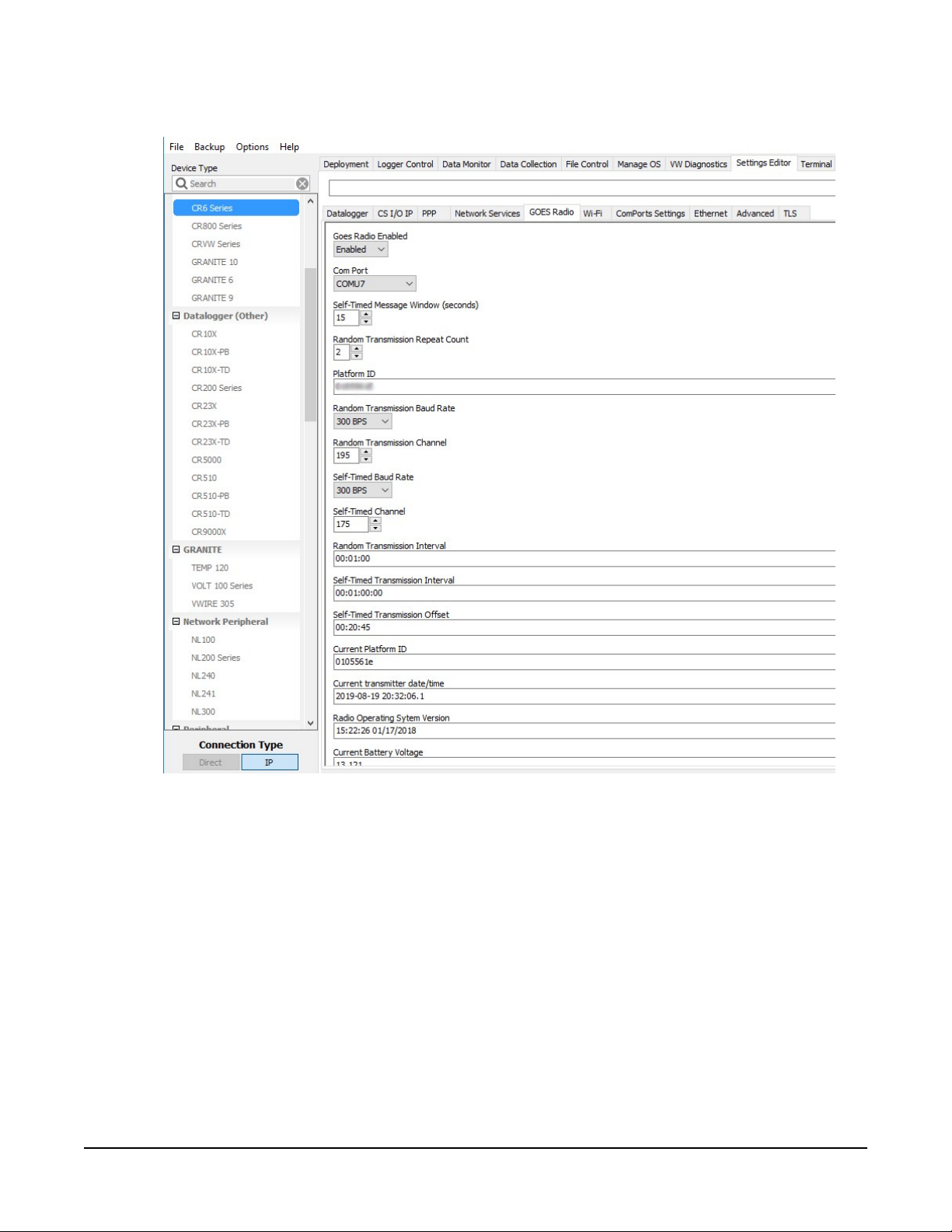
4. Click the GOES Radio sub tab (FIGURE 4-1 (p. 3)).
FIGURE 4-1. Device Configuration Utility GOES Radio screen
5. Select Enabled from the Goes Radio Enabled field.
6. Select the Com Port to which the GOES radio is connected.
7. Type the Self-timed Message Windows (in seconds) as assigned by the GOES DCS Program.
8. Type the Platform ID (in HEX) as assigned by the GOES DCS Program.
9. Select the Random Transmission Baud Rate as assigned by the GOES DCS Program.
10. Type the Random Transmission Channel as assigned by the GOES DCS Program.
11. Select the Self-Time Baud Rate as assigned by the GOES DCS Program.
TX325 Satellite Transmitter for GOES V2 3
Page 7
12. Type the Self-Time Channel as assigned by the GOES DCS Program.
13. Type the Random Transmission Interval as assigned by the GOES DCS Program. Format is
hh:mm:ss.
14. Type the Self-timed Transmission Interval as assigned by the GOES DCS Program. Format is
dd:mm:hh:ss.
15. Type the Self-timed Transmission Offset as assigned by the GOES DCS Program. Format is
hh:mm:ss.
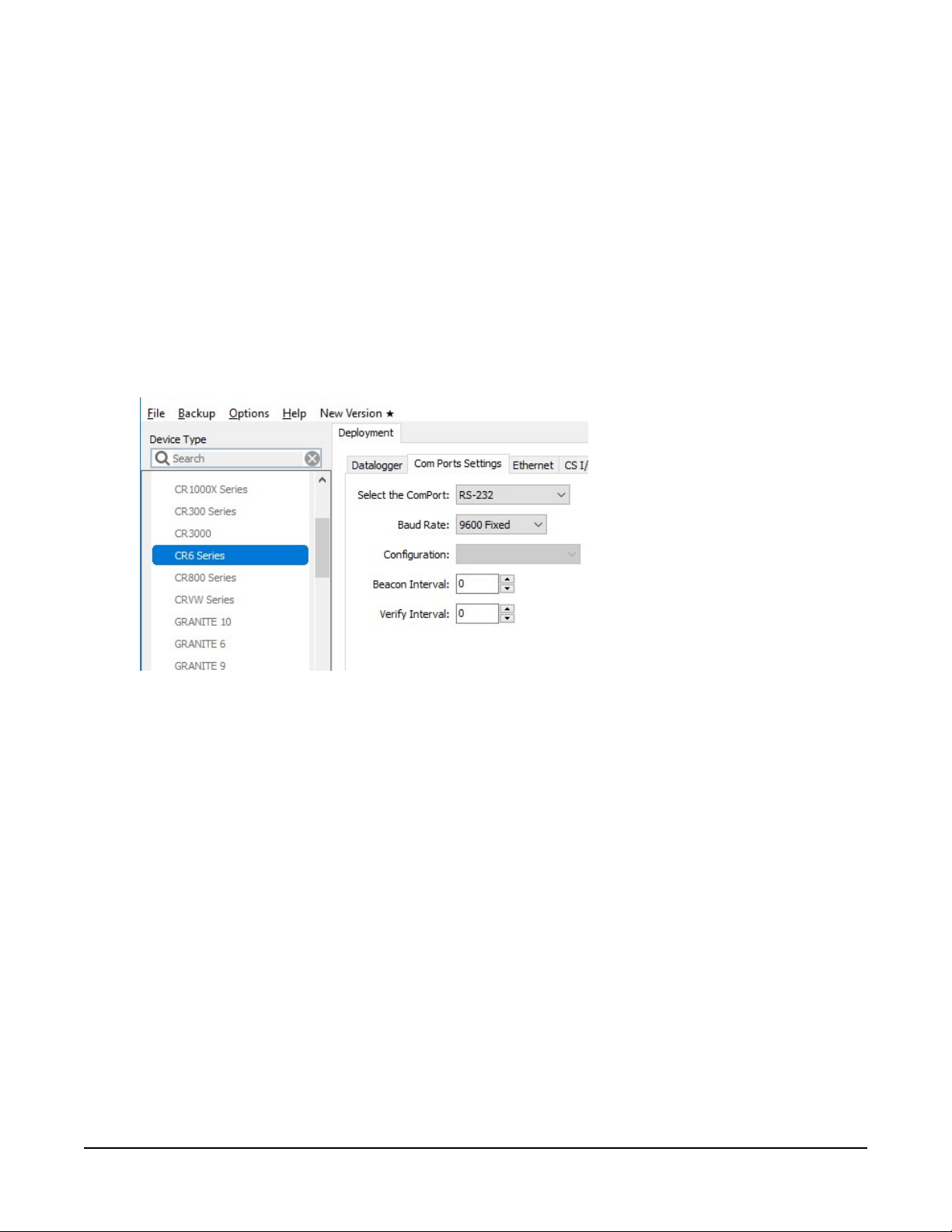
16. Click the Deployment tab.
17. Click the Com Port Settings sub tab.
18. Select 9600 for the Baud Rate.
19. Click Apply to save the changes.
Now the settings are stored in the data logger. CRBasic programming is required to push data
over the network. The GOESTable() and GOESField() CRBasic instructions used in
conjunction with DataTable() facilitate the transmission of data across the GOES satellite
network.
4.1 Data collection platform (DCP) installation
1. Yagi antenna installation procedure:
a. Mount the Yagi antenna to a pole or mast by using the U-bolts included with the
antenna mount.
TX325 Satellite Transmitter for GOES V2 4
Page 8
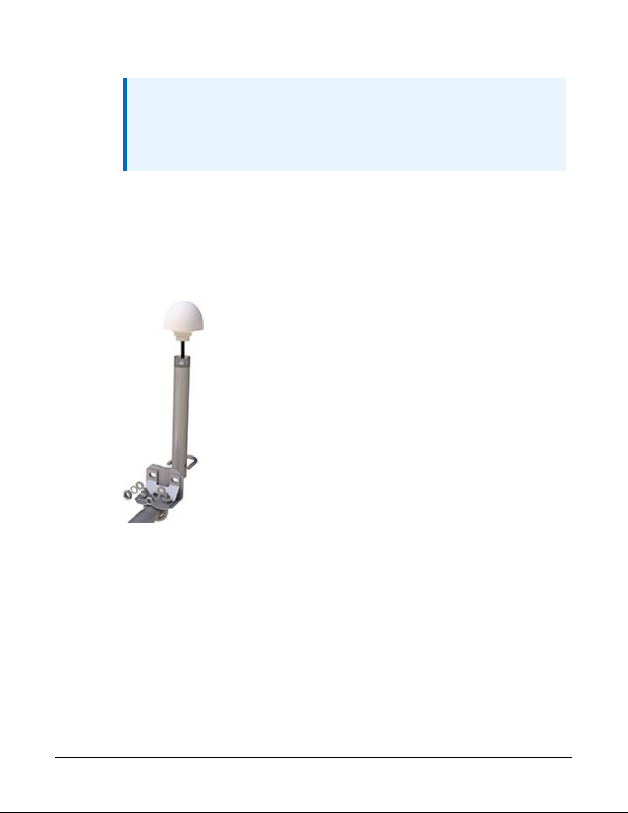
b. Attach elements to boom.
NOTE:
When attaching elements to the boom, make sure to place them such that the
number of grooves on the element equals the number of dimples on the boom.
For example, the element with four grooves should be placed at the spot on the
boom with four dimples, and so forth.
c. Aim the Yagi antenna at the spacecraft; azimuth and elevation angle positions are
included on the bracket label.
2. GPS antenna installation procedure:
a. Connect the GPS cable to the GPS antenna.
b. Route the cable through the 0.75-inch IPS threaded pipe and insert the pipe into the
GPS antenna.
TX325 Satellite Transmitter for GOES V2 5
Page 9
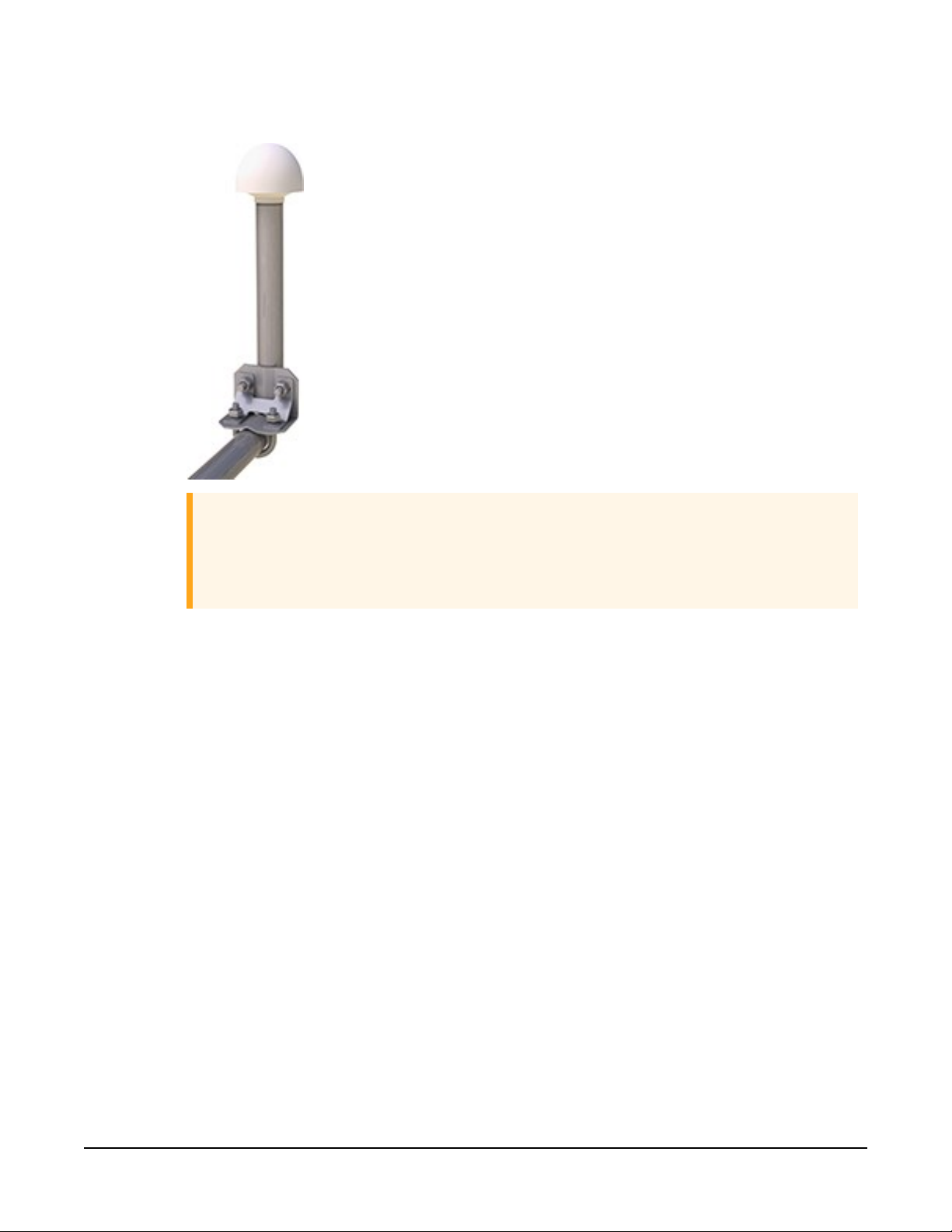
c. Mount the 0.75-inch IPS threaded pipe to a crossarm by using the Nu-Rail® fitting,
or CM220 mounting bracket.
CAUTION:
The GPS antenna will not receive a GPS signal through steel roofs or steel walls.
Concrete might also be a problem. Heavy foliage, snow, and ice will attenuate
the GPS signal.
3. Mount the TX325, the power supply, and the data logger to the backplate of an enclosure.
4. Mount the enclosure and solar panel to the pole or tripod.
TX325 Satellite Transmitter for GOES V2 6
Page 10
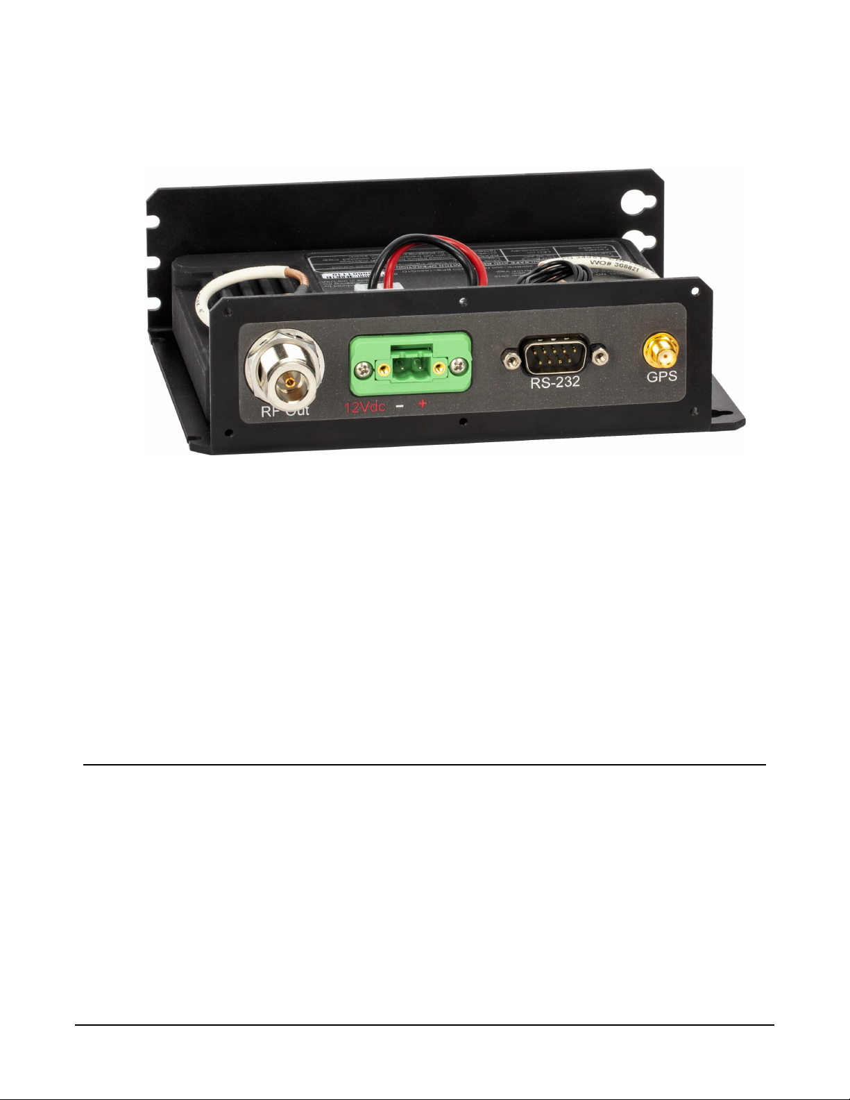
5. Connect the COAXNTN cable to the Yagi antenna. Route the COAXNTN cable through the
enclosure conduit and connect it to the RF Out connector on the TX325 (FIGURE 4-2 (p.
7)).
FIGURE 4-2. TX325 connectors
6. Route the GPS antenna cable through the enclosure conduit and connect it to the GPS
connector on the TX325 (FIGURE 4-2 (p. 7)).
7. Plug the green connector from the power supply to the green receptacle on the TX325.
8. Connect the data logger to the TX325 RS-232 terminal.
9. Route the solar panel cable through the enclosure conduit and connect the red and black
wires to the CHG terminals on the CH150 or CH200.
5. Overview
The TX325 can transmit either self-timed or random GOES messages to the GOES West and GOES
East satellites. In a typical configuration, the TX325 is connected to a data logger via an RS-232
serial connection. The data logger makes measurements, then formats those values to create a
data packet, which is transferred to the transmitter at time of transmission. The data logger
buffers the message until its transmission window (or random transmission time), then transmits
the data at either 300 or 1200 bps.
TX325 Satellite Transmitter for GOES V2 7
Page 11

GPS is required for the radio to work in the GOES network. The GOES network is a TDMA
network that requires all the radios in the network to have exact timing of their transmissions so
they don't step on each other during transmissions. Extremely accurate timing is obtained from
the integrated GPS receiver (±100 μs), and the internal clock is capable of maintaining accurate
time for a minimum of six days without a GPS fix. If the TX325 finds itself without an accurate
time, it suspends data transmissions until an accurate time is obtained. The GPS time is synched
every 11 hours. The data logger clock is synched with the GPS time of the TX325 when using a
GRANITE-series, CR6, CR1000X-series, and CR300-series data logger.
Features:
l NESDIS HDR V2 certified
l Based on Signal Engineering OmniSat3 design
l Compatible with GOES DCS system
l Easy integration with Campbell Scientific data loggers
l Field tested and proven track record of reliability
l Embedded GPS receiver for stabilized internal time keeping and transmit frequency for
long service intervals
l Low standby current consumption for battery-powered systems at remote DCP installation
sites
l Quick assessment of radio health via monitoring of diagnostic data from the radio
l Compatible CRBasic data loggers: GRANITE series, CR6, CR1000X, and CR300 series are fully
compatible. The CR3000, CR800 series, and CR1000 have limited compatibility.
5.1 GOES, NESDIS, and transmit windows
GOES coverage area is latitude 68° North to 68° South and longitude 150° East to 2° West (see
FIGURE 5-1 (p. 9)). GOES satellites have orbits that coincide with the Earth rotation, allowing each
satellite to remain above a specific region (geosynchronous). GOES has two satellites: GOES East
located at 75° West longitude and GOES West located at 135° West longitude. Both satellites are
located over the equator. Within the United States, odd-numbered channels are assigned to
GOES East, and even-numbered channels are assigned to GOES West. Channels used outside of
the United States are assigned to either spacecraft.
TX325 Satellite Transmitter for GOES V2 8
Page 12
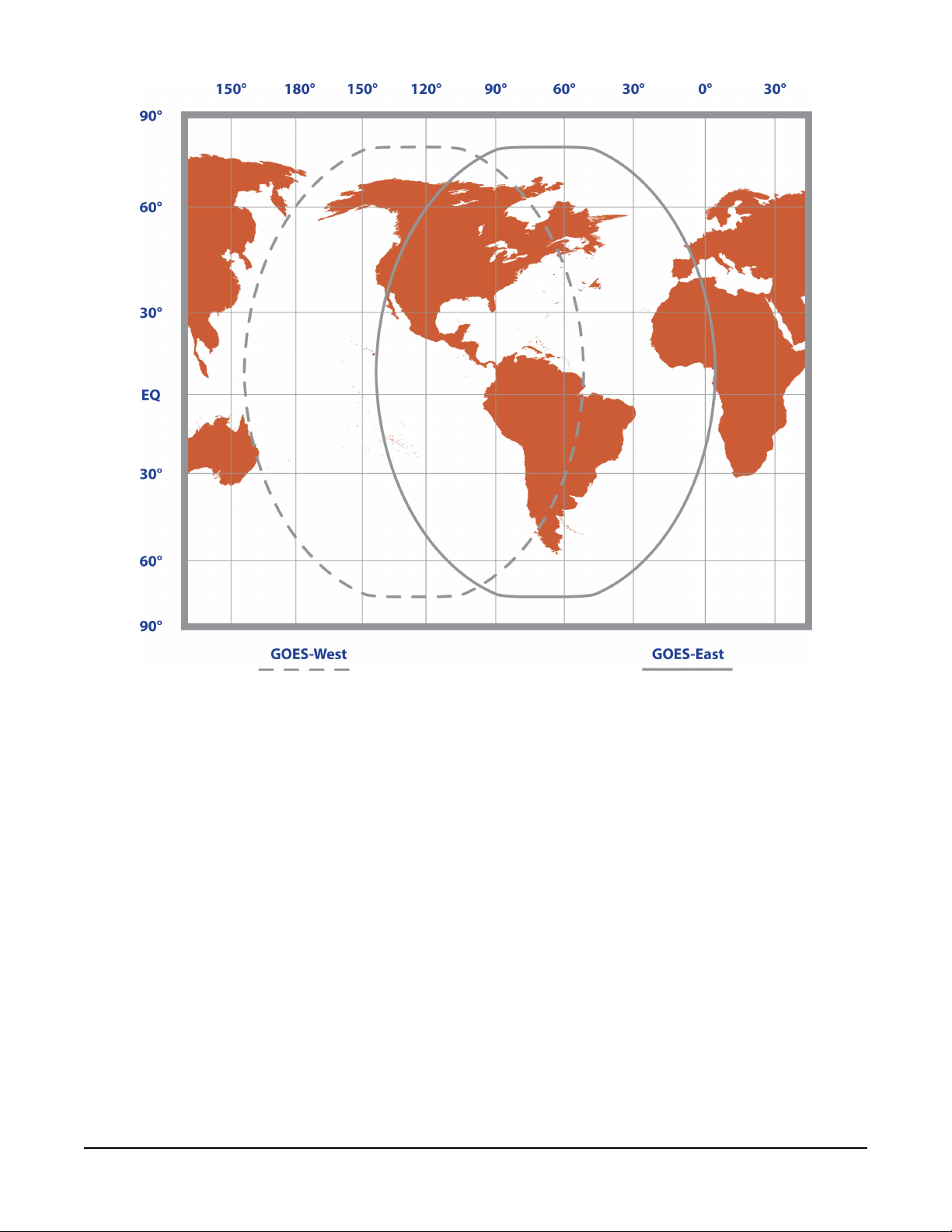
FIGURE 5-1. Coverage of GOES East and GOES West satellites
The GOES system is administered by the National Environmental Satellite Data Information
Service (NESDIS), which assigns addresses, uplink channels, and self-timed/random transmit time
windows. Self-timed windows allow data transmission only during a predetermined time frame
(typically 10 seconds every hour). Random windows are for applications of a critical nature, such
as flood reporting, and allow transmission immediately after a threshold has been exceeded. The
transmission is randomly repeated to ensure it is received. A combination of self-timed and
random transmission can be executed by the TX325.
Refer to Eligibility and getting onto the GOES system (p. 23) for more information.
TX325 Satellite Transmitter for GOES V2 9
Page 13

6. Specifications
Compliance:
Transmissions supported:
Data formats: ASCII (SHEF),
Radio module:
Temperature range
Operating:
Storage:
Case dimensions
Without connectors:
With connectors:
Weight:
Supply voltage range:
Refer to
www.campbellsci.com/tx325
Timed (Scheduled), Random
OmniSat-3
–40 to 60 °C
–55 to 75 °C
15.88 x 12.7 x 4.57 cm (6.25 x 5 x 1.8 in)
15.88 x 14.99 x 4.57 cm (6.25 x 5.9 x 1.8 in)
additional clearance required for cables, wires, and antennas
0.77 kg (1.7 lb)
10.5 to 16 VDC
Compliance documents and certificates (p. 40)
and
pseudo binary
Current drain at 12 VDC
While transmitting: < 2.5 A
Standby:
During GPS acquisition: < 50 mA
Baud rates: 300
Transmit power
Maximum: 31 dBm (300 bps), 37 dBm
Maximum EIRP: 41 dBm (300 bps), 47 dBm
Typical EIRP: 37 to 41 dBm (300 bps)
Frequency range:
< 5 mA (2.8 typical)
11 dbm gain antenna with 1 dbm line loss
43 to 47 dBm
401.701 to 402.09925 MHz
(1.8 typical)
(25 mA typical)
and 1200 bps
(1200 bps)
(1200 bps)
(1200 bps); based on a
,
TX325 Satellite Transmitter for GOES V2 10
Page 14
Initialfrequencystability:
±20 Hz disciplined to GPS (GPS fix occurs after power up and
once per day thereafter)
Channel bandwidth:
GPS receiver type:
Maximum GPS antenna RF
gain:
Timekeeping
Initial accuracy:
Drift:
GPS schedule:
Transmissioncontinuation
without GPS fix:
Interface connectors
RS-232:
Satellite RF transmit out:
GPS:
1500 Hz
3.3 V active
25 dB
±100 μs (synchronized to GPS)
±40 ms/day (without GPS)
1 fix at power up (updated at ~11-hour rate)
6 days
DB9 F, DCE, 3-wire RS-232
Type N jack
SMA jack
(300 bps), 2250 Hz (1200 bps)
Power:
2-pin screw terminal, 0.2 in. pitch
7. Installation
7.1 Field site requirements 11
7.2 LED function 12
7.3 Ports and connectors 13
7.4 Transmission antenna 14
7.5 GPS antenna 14
7.6 Data logger programming 14
7.1 Field site requirements
The GPS antenna must have a clear view of most of the sky and the transmission antenna must
have a clear view of the spacecraft. The TX325 must be installed in a well desiccated,
TX325 Satellite Transmitter for GOES V2 11
Page 15
environmentally sealed enclosure. Its mounting plate has keyholes for securing the TX325 to the
backplate of a Campbell Scientific enclosure. Most GOES systems are powered by a battery
charged by a solar panel. The solar panel must have a clear view of the southern sky. Pay special
attention to winter sun angles.
7.2 LED function
A green Status LED and a red Failsafe LED indicate the state of the TX325 transmitter by using
various blink patterns. Table 7-1 (p. 12) and Table 7-2 (p. 12) provide the blink patterns for the
green Status and red Failsafe LEDs, respectively.
Table 7-1: Green LED Status indicator blink patterns
Blink pattern Indicates
Normal software is running.
At power up, blinks on and off
two times.
At power up, blinks on and off
three times.
On continuously.
Table 7-2: Red LED Failsafe indicator blink patterns
Blink pattern Indicates
Blinks on and off four times per
second.
Blinks on and off two times per
second for 30 s.
RS-232 control interfaces enabled.
Power-up initialization complete and ready to receive
commands.
Bootloader software is running.
Ready to load new operating system.
Transmitter failed to start up normally after power up. Turn
the transmitter off and on to reboot.
A transmission is in progress.
The post-transmit interval is in progress. The transmitter
enters this state after its RF output is turned off either by a
Reset command or by the normal completion of a data
message transmission. The radio needs to wait 30 seconds
before making another transmission to keep it from going
into Failsafe mode.
On continuously.
TX325 is in the Failsafe mode. To clear a Failsafe mode, push
the Reset button (FIGURE 8-1 (p. 20)). A power cycle will NOT
clear the Failsafe mode.
TX325 Satellite Transmitter for GOES V2 12
Page 16
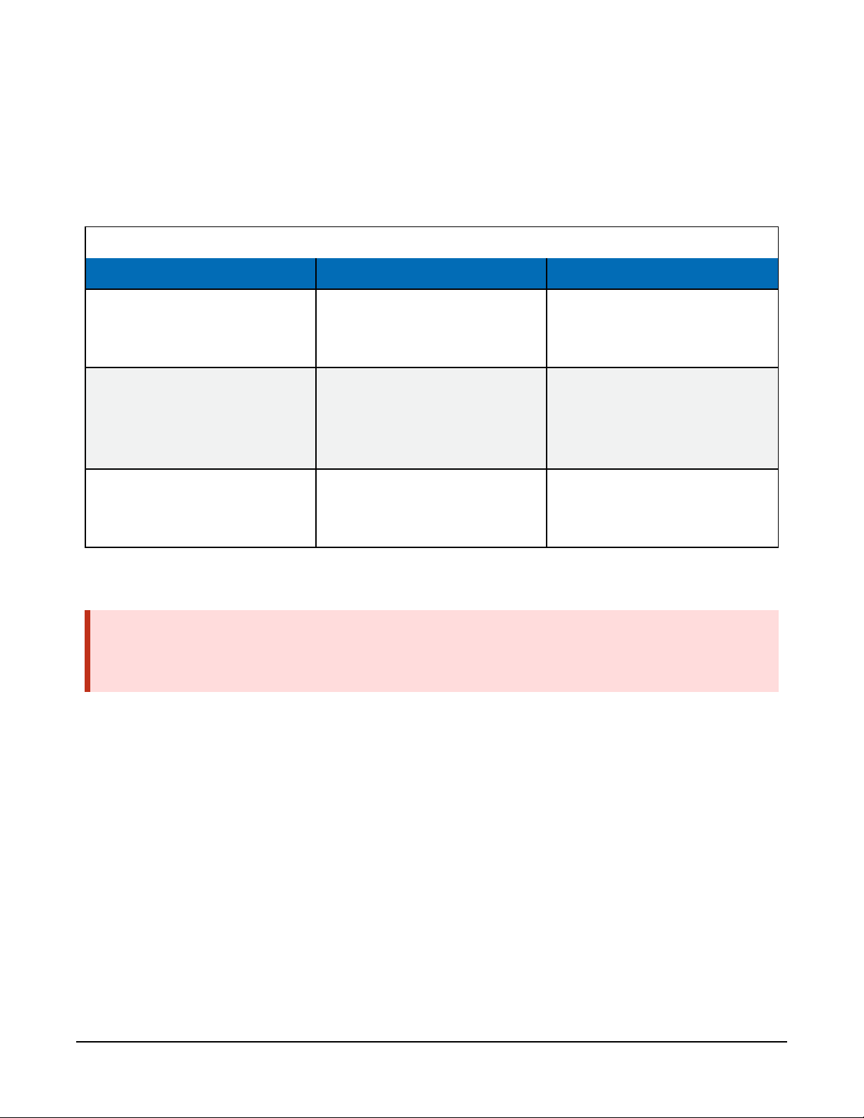
7.3 Ports and connectors
The RS-232 port is a DB9 male connector configured as DTE. Only three pins are used, transmit
on pin two, receive on pin three, and ground on pin five. Transmit is an output and receive is an
input to the TX325. The RS-232 port allows the transmitter to be connected to a data logger.
Refer to the following table for the cable options and data logger connection.
Table 7-3: Cable options, data logger compatibility, and data logger connections
Cable description Compatible data loggers Data logger connection
RJ45 to DB9 female cable (-R
option when ordered with the
TX325)
SC110 TX/RX cable (-C option
when ordered with the TX325)
Granite-series, CR6, CR1000X RS-232/CPI RJ45 port
White: Odd C or U terminal
Brown: Even C or U terminal
Granite-series, CR6, CR1000X
Yellow: G
Clear: G or ⏚
RS-232 DB9 female to DB9
male serial cable (-S option
when ordered with the TX325)
The RF Out connector is for attaching the transmission antenna. A properly matched antenna
cable and antenna must be connected to the TX325 before transmission occurs.
WARNING:
Failure to use a properly matched antenna cable and antenna may cause permanent damage
to the radio frequency (RF) amplifiers.
The nominal impedance is 50 ohms; the frequency range is approximately 400 to 403 MHz. At
300 bps transmission rates, the maximum transmit power is 31 dBm. At 1200 bps, the transmit
power is 37 dBm.
The GPS port on the TX325 is an SMA female connector for attaching an active 3.3 V GPS
antenna. Operation without a GPS antenna connected will not cause damage, but the
transmitter will not transmit without a valid GPS fix. The transmitter uses the GPS receiver for two
functions. The precise GPS time is used to ensure scheduled transmissions occur at the proper
time. The one-second GPS synchronization pulse is used to ensure a precise, drift-free carrier
frequency.
CR300-series, CR3000,
RS-232 9-pin port
CR800-series, CR1000
The TX325 power connector has two pins: ground and 12 V for connection of the power supply.
The input power requirement is 10.5 to 16 VDC can use up to 2.5 A. A power supply consisting of
TX325 Satellite Transmitter for GOES V2 13
Page 17
a CH150 or CH200 regulator, BP12 or BP24 battery, and a solar panel typically can support these
requirements. For this power supply, the regulator connects to the TX325 power connector.
7.4 Transmission antenna
The TX325 transmission antenna is a right-hand circular polarized Yagi with 11 dBi gain. A bracket
is included with the antenna for mounting to a mast or pole. The antenna is directional and
should be aimed at the spacecraft. Both elevation and azimuth are unique to the location on the
planet and must be set. A poorly aimed antenna will cause a drop in signal strength or possibly
prevent successful transmission. As a guide, if the antenna is aimed 20 degrees off the spacecraft,
the received power will be half of a properly aimed antenna. Beyond 20 degrees, the received
power drops off quickly.
NOTE:
When attaching elements to the boom, make sure to place them such that the number of
grooves on the element equals the number of dimples on the boom. For example, the
element with four grooves should be placed at the spot on the boom with four dimples, and
so forth.
7.5 GPS antenna
The GPS antenna mounts to the end of a crossarm by using a 0.75-inch IPS threaded pipe and a
0.75-inch-by-1-inch Nu-Rail® fitting or CM220 mounting bracket. Mount the GPS antenna
above obstructions, but with the shortest cable possible. The GPS antenna will not receive GPS
signals through steel roofs, steel walls, or possibly concrete. Heavy foliage, snow, and ice will
attenuate the GPS signal. An unobstructed view provides better GPS performance resulting in
fewer ( or no) missed transmissions. Poor GPS antenna placement increases the number of
missed transmissions, and possibly stops all GPS transmissions.
7.6 Data logger programming
NOTE:
This section provides programming information for the GRANITE-series (≥OS 1), CR6 (≥OS
10), CR1000X (≥OS 4), and CR300-series (≥OS 10), data loggers. For information on
programming the CR3000, CR800-series, and CR1000 data loggers, refer to the example
program at www.campbellsci.com/downloads/tx325-example-program-cr3000-cr1000-cr800
or contact Campbell Scientific.
TX325 Satellite Transmitter for GOES V2 14
Page 18

The CRBasic program can read and enter TX325 settings. Settings can also be entered using the
Device Configuration Utility (see QuickStart (p. 2)). Table 7-4 (p. 16) provides the TX325 settings
that can be read and entered. Table 7-5 (p. 17) provides the read-only settings.
The CRBasic program should include the GOESTable() and GOESField() instructions used
in conjunction with the DataTable() instruction to facilitate the transmission of data across
the GOES satellite network. The GOESTable() instruction has the following syntax:
GOESTable (Result, ComPort, Model, BufferControl, Fields_Scan_Order,Newest_
First,Format)
The Result is a string variable that holds either the data to be output in its specified format or
a message indicating there are no data to output to the transmitter. For the Model, enter 3 to
use the TX325. For the BufferControl, a value of 0 writes to the self-timed buffer and a value
of 1 writes to the random buffer. Data formats and transmission durations (p. 24) discusses the
Format options.
The GOESField() instruction has the following syntax:
GOESField(NumVals, Decimation, Precision, Width, SHEF)
The NumVals is the number of historical values of the field to output. For Decimation, enter
1 to output every value, enter 2 to output every other value, etc. Width specifies the number of
characters in the field. Use empty quotes ("") for SHEFif no SHEF code is specified.
An example of using the the GOESTable() and GOESField() instructions follows:
DataTable (ST_DATA, TRUE, -1)
DataInterval(0, 15, Min, 4)
GOESTable (st_table_results, COMRS232, 3, 0, TRUE, TRUE, 3)
GOESField (4, 1, 3, 6, "")
Sample (1, battery_voltage, IEEE4)
GOESField (4, 1, 3, 6, "")
Sample (1, panel_temperature, IEEE4)
EndTable
In the main portion of the program, settings are written using SetSetting() instruction with
the following the syntax:
SetSetting ( "FieldName", Value )
The FieldName must be enclosed in quotes as shown. The following example instruction sets
the port used to communicate with the TX325 to the RS-232 port:
SetSetting(“GOESComPort”, COMRS232)
The CRBasic program reads the TX325 settings using the following format:
Variable = Settings.FieldName
For example, goes_comport = Settings.GOESComPort reads the Com port setting and
stores it in the GOESComPort variable. The TX325 settings are typically read in a
TX325 Satellite Transmitter for GOES V2 15
Page 19
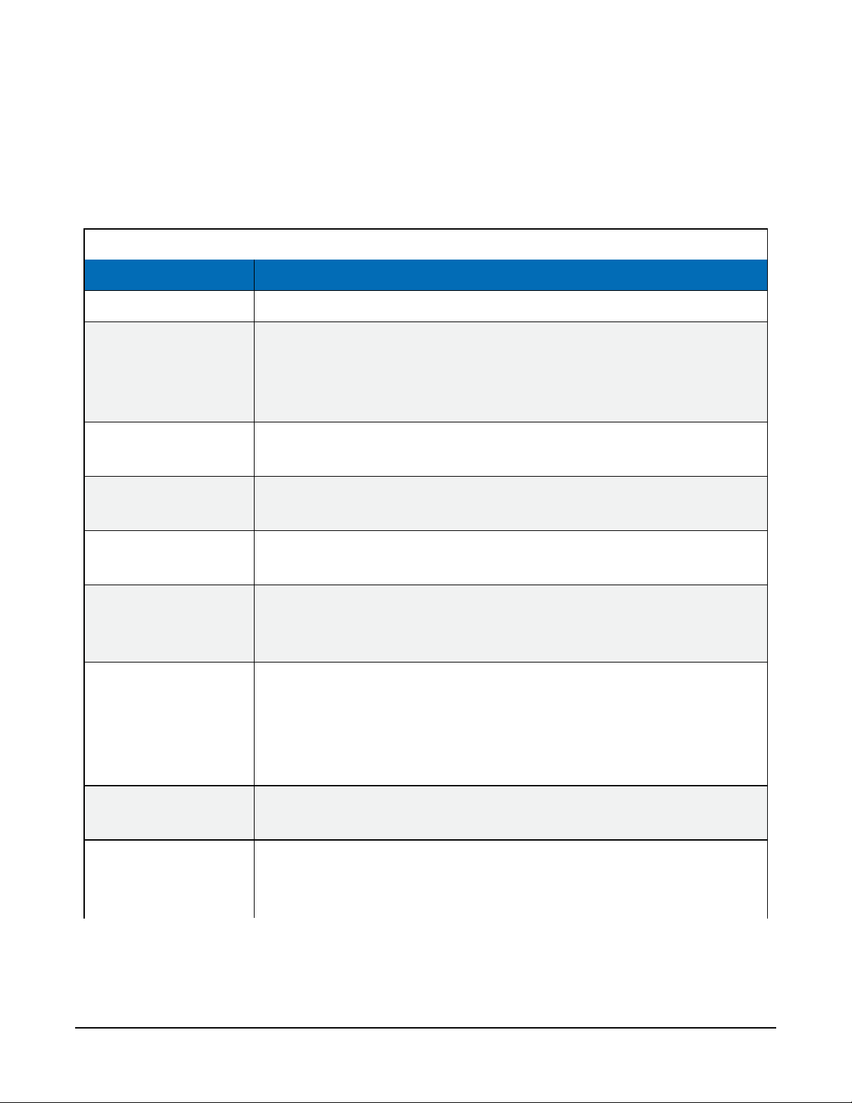
SlowSequence section of the program. Table 7-4 (p. 16) provides the TX325 settings that can
be set and read. Table 7-5 (p. 17) provides the read-only settings.
A downloadable example program is available at: www.campbellsci.com/downloads/tx325-
example-program-granite-cr6-cr1000x-cr300.
7.6.1 Read and write settings
Table 7-4: Read and write TX325 settings
Field Name Description
GOESComPort
GOESEnabled
GOESMsgWindow
GOESPlatformID
GOESRTBaudRate
GOESRTChannel
GOESRTInterval
Port used to communicate with the GOES transmitter.
Controls whether the data loggers polls the GOESComPort to see if a
TX325 radio is attached to it. With the default setting of 0 (not
enabled), the data logger ignores all other GOES settings. A value of 1
enables the setting.
Length, in seconds, of the assigned self-timed transmission window
assigned by NESDIS. Valid entries are 1 to 110 s.
8-digit hexadecimal identification number assigned by NESDIS. Value is
a string.
Baud rate for the random transmissions. Valid settings are 100, 300, or
1200. The baud rate must match the user's NESDIS-channel assignment.
Channel used for the random transmission assigned by NESDIS. Valid
channel numbers are 0 through 566. The default value of 0 disables
random transmissions.
Average time between random transmissions. The value is a string
entered in the format of “Hours:Minutes:Seconds”. Typically, the
assigned interval is in hours, so the minutes and seconds parameters are
left at 0. For example, “01:00:00” setups up an hourly interval. Maximum
interval is 24 hours; minimum interval is 1 minute.
GOESSTBaudRate
GOESSTChannel
Baud rate for self-timed transmissions. Valid settings are 300 or 1200.
The baud rate must match the user's NESDIS-channel assignment.
Channel used for the self-timed transmission assigned by NESDIS. Valid
channel numbers are 0 through 566. The default value of 0 disables the
self-timed transmissions.
TX325 Satellite Transmitter for GOES V2 16
Page 20
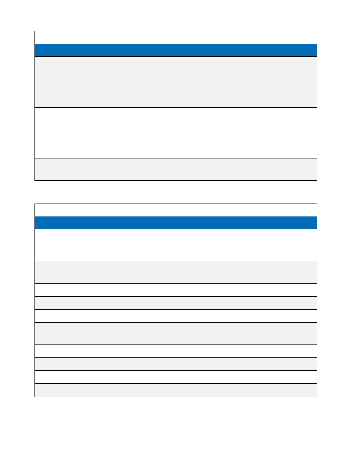
Table 7-4: Read and write TX325 settings
Field Name Description
Time between self-timed transmissions. The value is a string entered in
the format of "Days:Hours:Minutes:Seconds". Typically, the assigned
GOESSTInterval
GOESSTOffset
interval is in hours, so the days, minutes and seconds parameters are
left at 0. For example, "00:01:00:00" sets up an hourly interval. Maximum
interval is 14 days; minimum interval is 1 minute.
Time after midnight for the first self-timed transmission as assigned by
NESDIS. The value is a string entered in the format of
"Hours:Minutes:Seconds". Typically, only hours and minutes are used,
and seconds are 0, unless the transmission window is less than 60
seconds. Maximum offset is 23:59:59. A value 0 results in no offset.
GOESRepeatCount
Number of times within the random transmit interval that the TX325 will
transmit the message data. Valid entries are 1 to 3.
7.6.2 Read-only settings
Table 7-5: Read-only TX325 settings
FieldName Description
Current ID programmed into the radio. The ID isn’t
GOESid
GOESdateTime
GOESversion
GOESCurrentbattery
GOESCurrenttemperature
GOESbatteryBeforeTx
programmed into the radio until right before a radio
transmission starts.
Current date and time (UTC) of the TX325 radio. Value is a
string.
Current radio firmware version. Value is a string.
Battery voltage in VDC.
Current radio temperature in degrees Celsius.
Battery voltage of the radio just prior to its last
transmission.
GOEStemperatureBeforeTx
GOESbatteryDuringTx
GOESLatitude
GOESLongitude
Radio temperature before the last transmission.
Radio-battery voltage during the last transmission.
Latitude in decimal format of the GOES radio.
Longitude in decimal format of the GOES radio.
TX325 Satellite Transmitter for GOES V2 17
Page 21
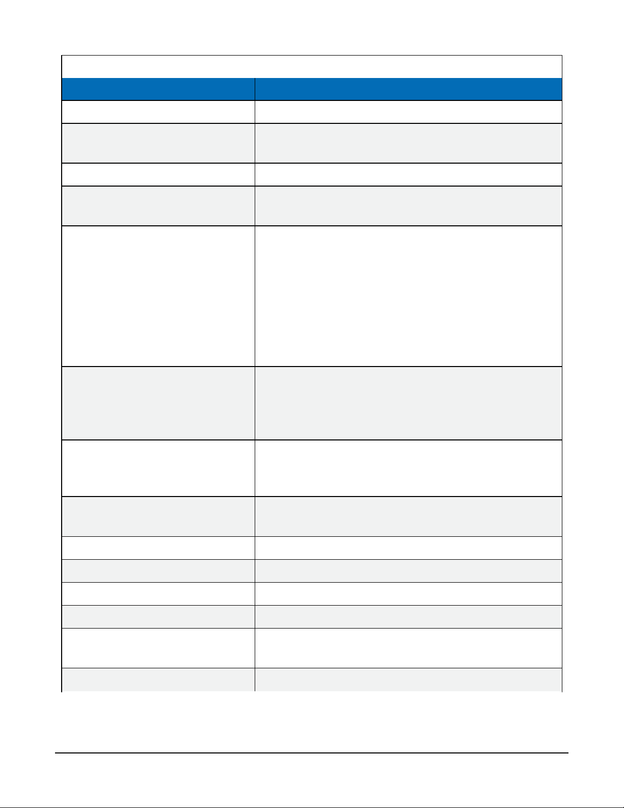
Table 7-5: Read-only TX325 settings
FieldName Description
GOESAltitude
GOESTimeLastGPSPosition
GOESNumberOfMissedGPS
GOESTimeLastMissedGPSFix
GOESGPSAcquisitionStatus
GOESGPSAntennaStatus
Altitude of the GOES radio in meters.
Date and time (UTC) of the last GPS position fix. Value is a
string.
Number of times the radio has failed to get a GPS fix.
Last date and time (UTC) that the radio failed to get a GPS
fix. Value is a string.
Acquisition status of the radio GPS.
0 = valid GPS fix
1 = no GPS position fix, no GPS satellites in view
8 = no GPS position fix, no usable GPS satellites in view
9 = no GPS position fix, one usable GPS satellite in view
10 = no GPS position fix, two usable GPS satellites in view
11 = no GPS position fix, three usable GPS satellites in
view
Status of the GPS antenna.
0 = GPS antenna is working
16 = GPS antenna is not connected
48 = GPS antenna is shorted
GOESFailSafeIndicator
GOESDurationOfTransmit
GOESForwardTxPower
GOESReflectedRfPower
GOESVSWR
GOESLastTxControlFlags
GOESLastTxStartTime
GOESLastTxChannel
Radio failsafe status.
1 = Failsafe has been tripped
0 = Radio is OK and Failsafe has not been tripped
Duration of the last transmission of the GOES radio in
milliseconds.
Forward RF power of the transmitter in watts.
Reflected RF power of the transmitter in watts.
Voltage standing wave ratio (SWR) of the radio.
Control flags used in the last transmission.
Start time (UTC) of the last radio transmission. Value is a
string.
Channel number used during the last radio transmission.
TX325 Satellite Transmitter for GOES V2 18
Page 22
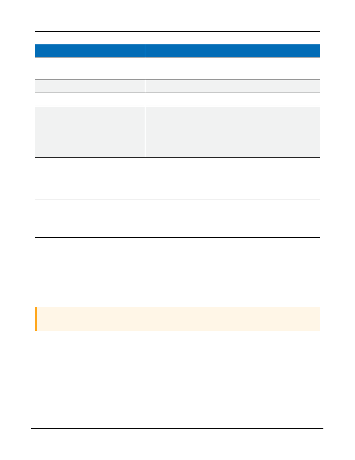
Table 7-5: Read-only TX325 settings
FieldName Description
GOESLastTypeCode
GOESLastDatelength
GOESLastHDRFlagWord
GOESTxResultCode
GOESCurrentTxState
Type of transmission used during the last radio
transmission.
Number of bytes in the last radio transmission.
HDR flag word used in the last radio transmission.
Status of the last radio transmission.
0 = Last transmission was OK
1 = Transmission aborted, radio battery voltage is too low
2 = Transmission aborted, radio PLL lock failure
3 = Transmission aborted, radio flash is corrupt
Current state of the radio.
0 = Idle
1 = Transmission is in progress
2 = Post transmission failsafe wait is in progress
8. Troubleshooting
Issue: TX325 is not transmitting
First, check the power supply and make sure that the TX325 power supply voltage is at least
10.5VDC (see Specifications (p. 10)). Next, check the red Failsafe LED. If the LED is on
continuously, the TX325 is in its fail safe mode, which is cleared by pressing the Reset button. The
Reset button is located near the LEDs and is accessed through a hole in the side of the
transmitter housing (FIGURE 8-1 (p. 20)).
CAUTION:
A power cycle will not clear the fail safe mode.
TX325 Satellite Transmitter for GOES V2 19
Page 23
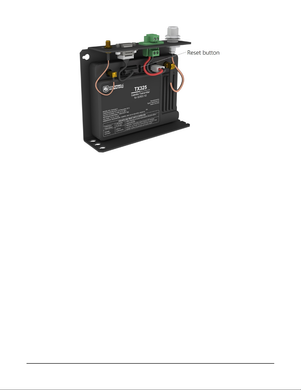
FIGURE 8-1. Reset button location
The TX325 transmitter will go into the fail safe mode if one of two events occurs:
1. The transmitter RF output is turned on and left on for more than 110 seconds.
2. The transmitter is given a command to transmit less than 30 seconds after a transmission
has taken place.
If a fail safe condition occurs, the red Failsafe LED is on continuously; its RF output is disabled;
and its microprocessor is reset (causing the transmitter to reboot). While in the fail safe mode,
the transmitter can communicate normally with the data logger, but is unable to transmit again
until the fail safe mode has been cleared.
8.1 Troubleshooting over-air transmissions
TX325 users within the GOES system can troubleshoot their over-the-air data transmissions by
using one of the following websites:
l https://dcs1.noaa.gov/Account/FieldTest
l https://dcs2.noaa.gov/Account/FieldTest
l https://dcs3.noaa.gov/Account/FieldTest
l https://dcs4.noaa.gov/Account/FieldTest
TX325 Satellite Transmitter for GOES V2 20
Page 24
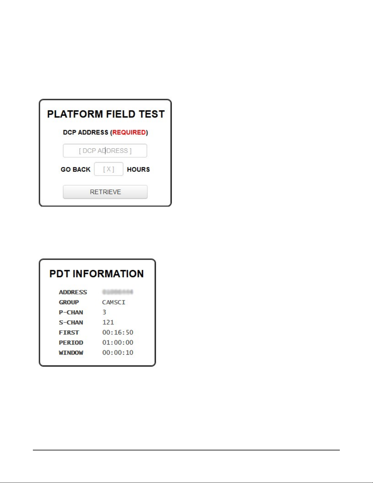
These websites provide the raw data sent through the GOES satellite system but do not require a
login, user name, nor password.
1. Type your eight-character DCP ADDRESS.
2. Type the number of hours you want the field test system to go back to.
3. Click RETRIEVE.
The PDT INFORMATION provides your assigned DCP address, channels, transmission times, and
window length. Make sure your setting in your DCP match this information. Failure to do so will
result in loss of data and transmitting over the top of other DCP scheduled slots and also will
result in the loss of other user’s data.
The bottom table shows information that can help you determine the health of the DCP
transmissions. This information includes signal quality (QUAL), transmission start time (CARRIER),
and stop time(END).
TX325 Satellite Transmitter for GOES V2 21
Page 25
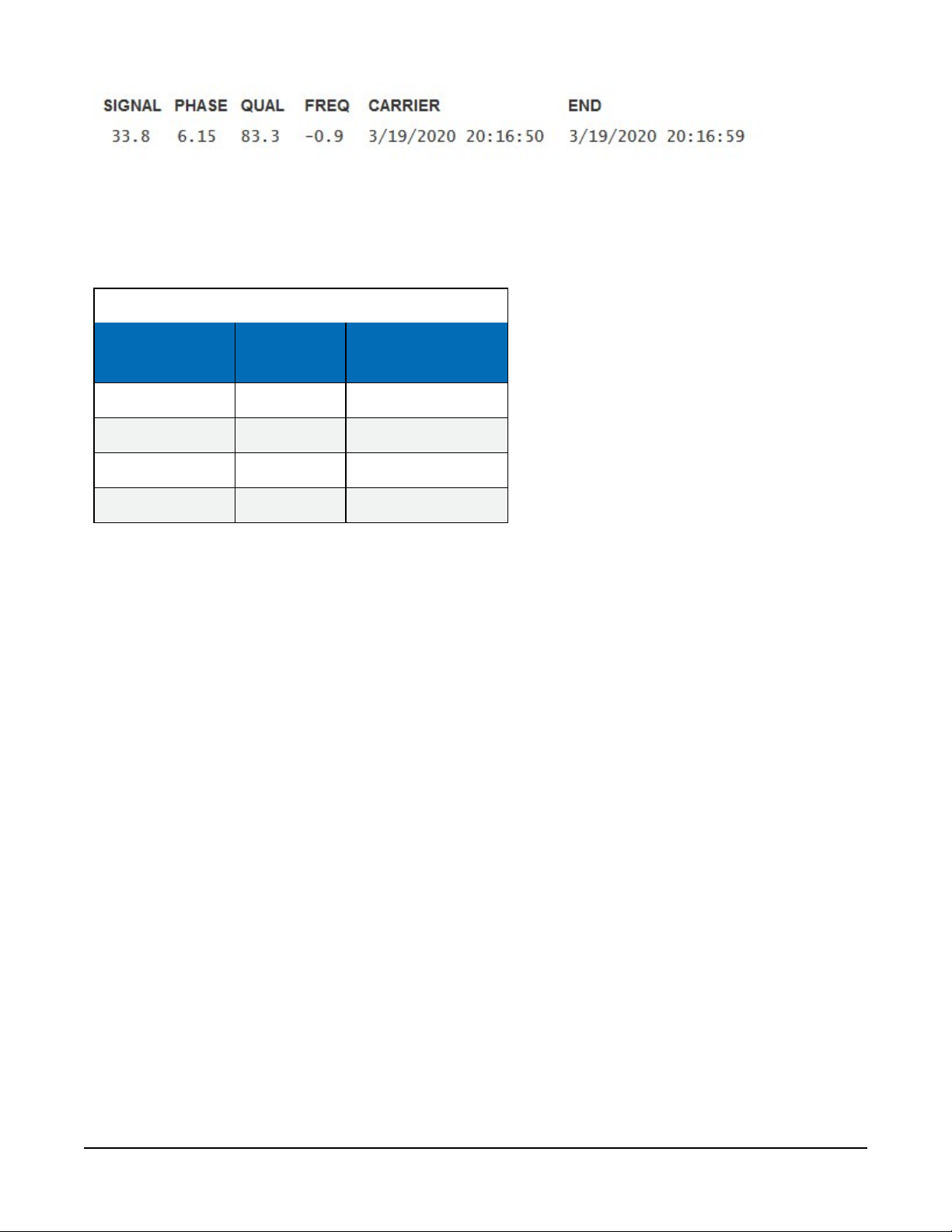
The DATA field provides the data transmitted through the GOES system. An extra character could
be in front of the transmitted data message, indicating whether or not the GPS time synched
(Table 8-1 (p. 22)). This character is added to the number of bytes (shown as LEN) that were in the
data transmission.
Table 8-1: Characters indicating time sync
Character Data type
Space ASCII No
Double quote (") ASCII Yes
Apostrophe (') Binary No
Lower case b Binary Yes
Time synched since
last transmission
TX325 Satellite Transmitter for GOES V2 22
Page 26

Appendix A. Eligibility and getting onto the GOES system
U.S. federal, state, or local government agencies, or users sponsored by one of those agencies,
may use GOES. Potential GOES users must apply for and be granted a System Use Agreement
(SUA) by NESDIS, which is typically renewable every 5 years. Use the following procedure to
acquire permission for getting onto the GOES system:
1. Follow the steps provided at: https://dcs2.noaa.gov to submit an application for GOES DCS
SUA. Once submitted, the approving authorities will review the application and notify you
within two weeks. If you are approved NESDIS will send you a Memorandum of Agreement
(MOA).
2. Sign and submit the MOA. After the MOA is approved, NESDIS will issue a channel
assignment and an ID address code.
3. IMPORTANT: Contact NESDIS to coordinate a start-up date.
See https://dcs2.noaa.gov for more information.
TX325 Satellite Transmitter for GOES V2 23
Page 27

Appendix B. Data formats and transmission durations
Data transmissions are generally described as having an ASCII or pseudobinary format. The
particular nature of how the data is formatted prior to sending the data over-the-air. The data
order in those transmissions is determined by the content and organization of the DataTables()
and execution of GOESTable() and GOESField(). Scan-order (interleaved) and channelorder data can be sent by using an ASCII or pseudobinary format with one of the native data
logger data format options. The flexibility of CRBasic allows virtually any message type to match
the decode system requirements.
B.1 ASCII data format
ASCII data formats are used to transmit data in plain readable text. This format is widely used for
random or alert transmissions. They can be used for self-timed messages. Several standard
formats are selectable within CRBasic. Formats not included can be easily formed using stringformatted data fields, allowing the content to be tailored to your application needs. Stringformatted data fields are limited to 13 characters for each field.
B.1.1 7-byte floating-point ASCII (GOESTable() format option 1)
The 7-byte floating-point ASCII data type is a fixed-width format with variable precision.
l Operating range of ±7999, depending on placement of decimal point (see Table B-1 (p.
25)).
l Variable precision of 0.001 to 1, depending on placement of decimal point (see Table B-1
(p. 25)).
l Precision (placement of decimal point) is automatically determined based on the
magnitude of the value (Table B-1 (p. 25)).
l Number are rounded to selected precision during conversion. For example, +12.345, will be
rounded to +12.35.
l Value is always 7 characters including a trailing comma.
l Value is always signed (+/-).
TX325 Satellite Transmitter for GOES V2 24
Page 28
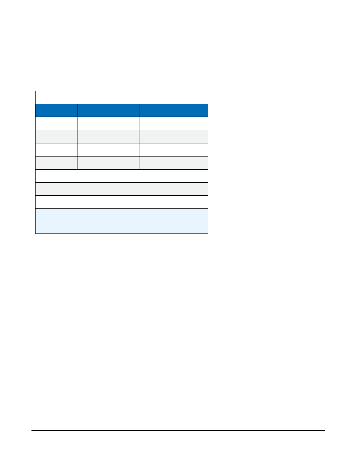
l Leading zeros and trailing zeros are added to maintain the width (7 characters) of the value
transmitted.
l Value always has a trailing comma. This includes the last value sent.
l Valid data outside of operating range are set to –7999 or +7999, unless it is a NAN, +INF,
or -INF (see Table B-1 (p. 25)).
Table B-1: 7-byte floating-point ASCII data
Range Maximum precision Example ASCII output
±7.999 0.001 +1.200,
±79.99 0.01 +12.00,
±799.9 0.1 +120.0,
±7999 1 +1200.,
NAN1= –8190.,
+INF2= +8191.,
-INF2= -8191.,
1
Not A Number
2
Infinity
Example output (with 10 fields):
GoesTable() Fields_Scan_Order = FALSE, Newest_First=FALSE, Format = 1
GoesField() Decimation = 1
<CR><LF>-7994.,-7994.,+8191.,-8191.,-8190.,+8191.,-8191.,-
8190.,+13.10,+27.32,
GoesTable() Fields_Scan_Order = FALSE, Newest_First=FALSE, Format = 1
GoesField() Decimation = 4
<CR><LF>-7997.,-7997.,+8191.,-8191.,-8190.,+8191.,-8191.,-
8190.,+13.15,+26.08,
<CR><LF>-7996.,-7996.,+8191.,-8191.,-8190.,+8191.,-8191.,-
8190.,+13.16,+26.04,
<CR><LF>-7995.,-7995.,+8191.,-8191.,-8190.,+8191.,-8191.,-
8190.,+13.17,+26.03,
<CR><LF>-7994.,-7994.,+8191.,-8191.,-8190.,+8191.,-8191.,-
8190.,+13.19,+26.18,
TX325 Satellite Transmitter for GOES V2 25
Page 29

GoesTable() Fields_Scan_Order = True, Newest_First=FALSE, Format = 1
GoesField() Decimation = 1
<CR><LF> -7994.,
<CR><LF> -7994.,
<CR><LF> +8191.,
<CR><LF> -8191.,
<CR><LF> -8190.,
<CR><LF> +8191.,
<CR><LF> -8191.,
<CR><LF> -8190.,
<CR><LF> +13.13,
<CR><LF> +27.72,
GoesTable() Fields_Scan_Order = True, Newest_First=FALSE, Format = 1
GoesField() Decimation = 4
<CR><LF>-7997.,-7996.,-7995.,-7994.,
<CR><LF>-7997.,-7996.,-7995.,-7994.,
<CR><LF>+8191.,+8191.,+8191.,+8191.,
<CR><LF>-8191.,-8191.,-8191.,-8191.,
<CR><LF>-8190.,-8190.,-8190.,-8190.
<CR><LF>,+8191.,+8191.,+8191.,+8191.,
<CR><LF>-8191.,-8191.,-8191.,-8191.,
<CR><LF>-8190.,-8190.,-8190.,-8190.,
<CR><LF>+13.12,+13.12,+13.12,+13.11,
<CR><LF>+27.59,+27.59,+27.59,+27.60,
B.1.2 ASCII table space (GOESTable() format option 2)
This option provides a tabular format. Columns are fixed width, according to the field format,
and are space delimited. Lines are <CR><LF> delimited. You can send either the newest or
oldest data first. A <CR><LF> is added at the end of the final line sent.
l NANs, +INFs, -INFs, and missing values show as forward slashes (/) in the output.
l Each line contains all the values listed in GOESTable() that have been set with
GOESField() and are sent in the order they are listed in the data table if Scan_Order
is set to False.
l Each line has all data from a single sensor if Scan_Order is set to True.
l SHEF Codes can be added as headers or at the beginning of lines using GOESField()
option SHEF.
l Value has a fixed width (Table B-2 (p. 27)).
l Value has a fixed precision (Table B-2 (p. 27)).
l Value only has a leading sign when negative (–).
TX325 Satellite Transmitter for GOES V2 26
Page 30
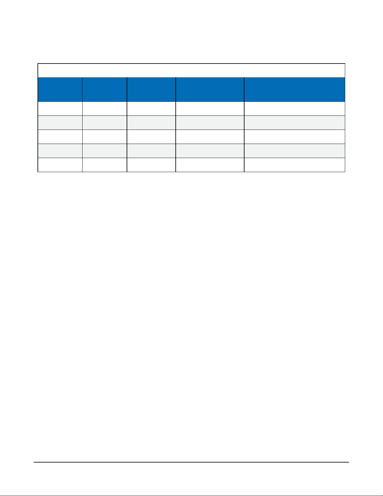
l Data outside of operating range will be set to the minimum or maximum of the range.
l Value always has a trailing space character.
Table B-2: ASCII format, width, precision, and range
Format Width Precision Range
Example ASCII output
containing two values
xxx 3 1 –99 to 999 012 -34
xxxxx 5 1 –9999 to 99999 00012 -0034
xxx.x 5 0.1 –99.9 to 999.9 001.2 -03.4
xx.xx 5 0.01 –9.99 to 99.99 00.12 -0.34
x.xxx 5 0.001 –.999 to 9.999 0.012 -.034
Example outputs (with 10 fields):
GoesTable() Fields_Scan_Order = FALSE, Newest_First=FALSE, Format = 2
GoesField() Decimation = 1, Precision = 3, Width = 4
<CR><LF>-7.982 -7.982 //// //// //// //// //// //// 13.1 25.8<CR><LF>
GoesTable() Fields_Scan_Order = FALSE, Newest_First=FALSE, Format = 2
GoesField() Decimation = 4, Precision = 3, Width = 5
<CR><LF>-9.81 -9.81 ///// ///// ///// ///// ///// ///// 13.15 26.08
<CR><LF>-9.80 -9.80 ///// ///// ///// ///// ///// ///// 13.13 26.08
<CR><LF>-9.79 -9.79 ///// ///// ///// ///// ///// ///// 13.14 26.08
<CR><LF>-9.78 -9.78 ///// ///// ///// ///// ///// ///// 13.14 26.08<CR><LF>
GoesTable() Fields_Scan_Order = TRUE, Newest_First=FALSE, Format = 2
GoesField() Decimation = 1, Precision = 3, Width = 5
<CR><LF>-9.68
<CR><LF>-9.68
<CR><LF>/////
<CR><LF>/////
<CR><LF>/////
<CR><LF>/////
<CR><LF>/////
<CR><LF>/////
<CR><LF>13.12
<CR><LF>26.43<CR><LF>
TX325 Satellite Transmitter for GOES V2 27
Page 31

GoesTable() Fields_Scan_Order = TRUE, Newest_First=FALSE, Format = 2
GoesField() Decimation = 4, Precision = 3, Width = 5
<CR><LF>-9.45 -9.44 -9.43 -9.42
<CR><LF>-9.45 -9.44 -9.43 -9.42
<CR><LF>///// ///// ///// /////
<CR><LF>///// ///// ///// /////
<CR><LF>///// ///// ///// /////
<CR><LF>///// ///// ///// /////
<CR><LF>///// ///// ///// /////
<CR><LF>///// ///// ///// /////
<CR><LF>13.13 13.14 13.13 13.13
<CR><LF>26.24 26.24 26.24 26.24<CR><LF>
GoesTable() Fields_Scan_Order = FALSE, Newest_First=FALSE, Format = 2
GoesField() Decimation = 1, Precision = 3, Width = 5, SHEF set to HG, TA, VB
<CR><LF>HG TA VB
<CR><LF>-7.94 13.13 26.72<CR><LF>
GoesTable() Fields_Scan_Order = FALSE, Newest_First=FALSE, Format = 2
GoesField() Decimation = 4, Precision = 3, Width = 5, SHEF set to HG, TA, VB
<CR><LF>HG TA VB
<CR><LF>-8.32 13.14 26.74
<CR><LF>-8.31 13.14 26.74
<CR><LF>-8.30 13.14 26.74
<CR><LF>-8.29 13.14 26.74<CR><LF>
GoesTable() Fields_Scan_Order = TRUE, Newest_First=FALSE, Format = 2
GoesField() Decimation = 1, Precision = 3, Width = 5, SHEF set to HG, TA, VB
<CR><LF>HG -6.79
<CR><LF>TA 13.12
<CR><LF>VB 26.68<CR><LF>
GoesTable() Fields_Scan_Order = TRUE, Newest_First=FALSE, Format = 2
GoesField() Decimation = 4, Precision = 3, Width = 5, SHEF set to HG, TA, VB
<CR><LF>HG -8.26 -8.25 -8.24 -8.23
<CR><LF>TA 13.14 13.14 13.13 13.14
<CR><LF>VB 26.76 26.76 26.76 26.76<CR><LF>
GoesTable() Fields_Scan_Order = TRUE, Newest_First=FALSE, Format = 2
GoesField() Decimation = 4, Precision = 3, Width = 5, SHEF set to HG, TA, VB
NOTE:
To get a single battery voltage (or other additional data), set GoesField() Decimation =
1 for just the battery_voltage (or other) value in the GOESTable().
TX325 Satellite Transmitter for GOES V2 28
Page 32

<CR><LF>HG -9.70 -9.69 -9.68 -9.67
<CR><LF>TA 13.11 13.13 13.10 13.13
<CR><LF>VB 26.82 26.82 26.82 26.82
<CR><LF>BATTERY 13.13
<CR><LF>DATE 200336
<CR><LF>TIME 101500<CR><LF>
B.1.3 ASCII table space, comma separated (GOESTable() format option 3)
This option provides a tabular format. Columns are fixed width, according to the field format,
and are comma (,) delimited. Lines are <CR><LF> delimited. You can send either the newest or
oldest data first. A <CR><LF> is added at the end of the final line sent.
l NANs, +INFs, -INFs, and missing values show as forward slashes (/) in the output.
l Each line contains all the values listed in GOESTable() that have been set with
GOESField() and are sent in the order they are listed in the data table if Scan_Order
is set to False.
l Each line has all data from a single sensor if Scan_Order is set to True.
l SHEF Codes can be added as headers or at the beginning of lines using GOESField()
option SHEF.
l Value has a fixed width (Table B-2 (p. 27)).
l Value has a fixed precision (Table B-2 (p. 27)).
l Value only has a leading sign when negative (–).
l Data outside of operating range will be set to the minimum or maximum of the range.
l Value always has a trailing comma (,).
Example outputs (with 10 fields):
GoesTable() Fields_Scan_Order = FALSE, Newest_First=FALSE, Format = 3
GoesField() Decimation = 1, Precision = 3, Width = 4
<CR><LF>-7.982,-7.982,////,////,////,////,////,////,13.1,25.8<CR><LF>
GoesTable() Fields_Scan_Order = FALSE, Newest_First=FALSE, Format = 3
GoesField() Decimation = 4, Precision = 3, Width = 5
<CR><LF>-9.81,-9.81,/////,/////,/////,/////,/////,/////,13.15,26.08
<CR><LF>-9.80,-9.80,/////,/////,/////,/////,/////,/////,13.13,26.08
<CR><LF>-9.79,-9.79,/////,/////,/////,/////,/////,/////,13.14,26.08
<CR><LF>-9.78,-9.78,/////,/////,/////,/////,/////,/////,13.14,26.08<CR><LF>
TX325 Satellite Transmitter for GOES V2 29
Page 33

GoesTable() Fields_Scan_Order = TRUE, Newest_First=FALSE, Format = 3
GoesField() Decimation = 1, Precision = 3, Width = 5
<CR><LF>-9.68
<CR><LF>-9.68
<CR><LF>/////
<CR><LF>/////
<CR><LF>/////
<CR><LF>/////
<CR><LF>/////
<CR><LF>/////
<CR><LF>13.12
<CR><LF>26.43<CR><LF>
GoesTable() Fields_Scan_Order = TRUE, Newest_First=FALSE, Format = 3
GoesField() Decimation = 4, Precision = 3, Width = 5
<CR><LF>-9.45,-9.44,-9.43,-9.42
<CR><LF>-9.45,-9.44,-9.43,-9.42
<CR><LF>/////,/////,/////,/////
<CR><LF>/////,/////,/////,/////
<CR><LF>/////,/////,/////,/////
<CR><LF>/////,/////,/////,/////
<CR><LF>/////,/////,/////,/////
<CR><LF>/////,/////,/////,/////
<CR><LF>13.13,13.14,13.13,13.13
<CR><LF>26.24,26.24,26.24,26.24<CR><LF>
GoesTable() Fields_Scan_Order = FALSE, Newest_First=FALSE, Format = 3
GoesField() Decimation = 1, Precision = 3, Width = 5, SHEF set to HG, TA, VB
<CR><LF>HG,TA,VB
<CR><LF>-7.94,13.13,26.72<CR><LF>
GoesTable() Fields_Scan_Order = FALSE, Newest_First=FALSE, Format = 3
GoesField() Decimation = 4, Precision = 3, Width = 5, SHEF set to HG, TA, VB
<CR><LF>HG,TA,VB
<CR><LF>-8.32,13.14,26.74
<CR><LF>-8.31,13.14,26.74
<CR><LF>-8.30,13.14,26.74
<CR><LF>-8.29,13.14,26.74<CR><LF>
GoesTable() Fields_Scan_Order = TRUE, Newest_First=FALSE, Format = 3
GoesField() Decimation = 1, Precision = 3, Width = 5, SHEF set to HG, TA, VB
<CR><LF>HG,-6.79
<CR><LF>TA,13.12
<CR><LF>VB,26.68<CR><LF>
TX325 Satellite Transmitter for GOES V2 30
Page 34
GoesTable() Fields_Scan_Order = TRUE, Newest_First=FALSE, Format = 3
GoesField() Decimation = 4, Precision = 3, Width = 5, SHEF set to HG, TA, VB
<CR><LF>HG,-8.26,-8.25,-8.24,-8.23
<CR><LF>TA,13.14,13.14,13.13,13.14
<CR><LF>VB,26.76,26.76,26.76,26.76<CR><LF>
GoesTable() Fields_Scan_Order = TRUE, Newest_First=FALSE, Format = 3
GoesField() Decimation = 4, Precision = 3, Width = 5, SHEF set to HG, TA, VB
NOTE:
To get a single battery voltage (or other additional data), set GoesField() Decimation =
1 for just the battery_voltage (or other) value in the GOESTable().
<CR><LF>HG,-9.70,-9.69,-9.68,-9.67
<CR><LF>TA,13.11,13.13,13.10,13.13
<CR><LF>VB,26.82,26.82,26.82,26.82
<CR><LF>BATTERY,13.13
<CR><LF>DATE,200336
<CR><LF>TIME,101500<CR><LF>
B.1.4 Line SHEF (Standard Hydrological Exchange Format) (GOESTable() format option 6)
ASCII output using standardized SHEF codes in a format that is human readable.
l NANs, +INFs, -INFs, and missing values show as forward slashes (/) in the output.
l LABEL is the SHEF code (two character) parameter. Refer to
https://dcs1.noaa.gov/documents/SHEF%20Codes.pdf for details on SHEF codes.
l OFFSET is how long ago the sensor reading was made and stored in the GOESTable()
data table and is reported in number of minutes.
l INTERVAL is how often the measurement is made. This corresponds to DataInterval()
of the GOES data table or the scan interval if DataInterval() is not used.
l DATA is the data that is stored in the GOES table.
l APPENDED OPTIONS refers to data that can be appended to the transmission.
l SHEF Codes can be added as headers or at the beginning of lines using GOESField()
option SHEF.
l Value has a fixed width (Table B-2 (p. 27)).
l Value has a fixed precision (Table B-2 (p. 27)).
l Value only has a leading sign when negative (–).
l Data outside of operating range will be set to the minimum or maximum of the range.
TX325 Satellite Transmitter for GOES V2 31
Page 35
Format of data transmitted:
: <LABEL1> <OFFSET> #<INTERVAL> <DATA1> <DATA1> ... <DATA1)>
: <LABEL2> <OFFSET> #<INTERVAL> <DATA2> <DATA2> ... <DATA2> ...
: <LABEL(N)> <OFFSET> #<INTERVAL> <DATA(N)> <DATA(N)> ... <DATA(N)>
Example output with explanation:
GoesTable() Fields_Scan_Order = TRUE, Newest_First=FALSE, Format = 6
GoesField() Decimation = 4, Precision = 3, Width = 5, SHEF set to VB and TA
(see Table B-3 (p. 32))
<CR><LF><SPC>:VB<SPC>8<SPC>#15<SPC>13.15<SPC>13.13<SPC>13.18<SPC>13.19
<CR><LF><SPC>:TA<SPC>8<SPC>#15<SPC>26.76<SPC>26.76<SPC>26.85<SPC>26.98<CR><LF>
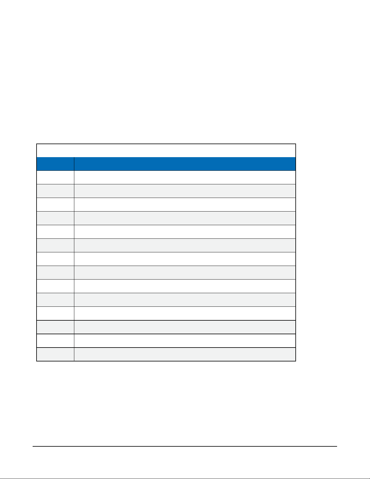
Table B-3: Example SHEF output with descriptions
Output Description
:VB SHEF Code VB (Voltage – Battery)
8 Reading is 8 minutes old (happened 8 minutes prior to transmission)
#15 15-minutes measurement interval
13.15 Most recent sensor or measurement reading
13.13 Sensor or measurement reading taken 15 minutes prior to transmission
13.18 Sensor or measurement reading taken 30 minutes prior to transmission
13.19 Sensor or measurement reading taken 45 minutes prior to transmission
:TA SHEF Code TA (Temperature, air, dry bulb)
8 Reading is 8 minutes old (happened 8 minutes prior to transmission)
#15 15-minutes measurement interval
26.76 Most recent sensor or measurement reading
26.76 Sensor or measurement reading taken 15 minutes prior to transmission
26.85 Sensor or measurement reading taken 30 minutes prior to transmission
26.98 Sensor or measurement reading taken 45 minutes prior to transmission
B.2 Pseudobinary data formats
The pseudobinary data format is a modified-ASCII format that uses the lower 6 bits of each 8-bit
data character to represent part of a binary message. To encode a number, its binary form is
broken into groups of 6 bits. Each group is placed into the lower 6 bits of a respective byte. The
TX325 Satellite Transmitter for GOES V2 32
Page 36
number 64 is added to each byte to set the seventh bit. Binary numbers are transmitted MSB
(most significant bit) first.
Pseudobinary formats are preferred for GOES and Meteosat/EUMETSAT self-timed transmissions
because users can include more data in the GOES message. This allows more data to be
transmitted in a specific window of transmission time.
NOTE:
These messages are not human readable and need to be decoded by computer software or
by using custom decoding tables.
Because only 6 bits are used in each byte, the range that a byte or series of bytes can represent is
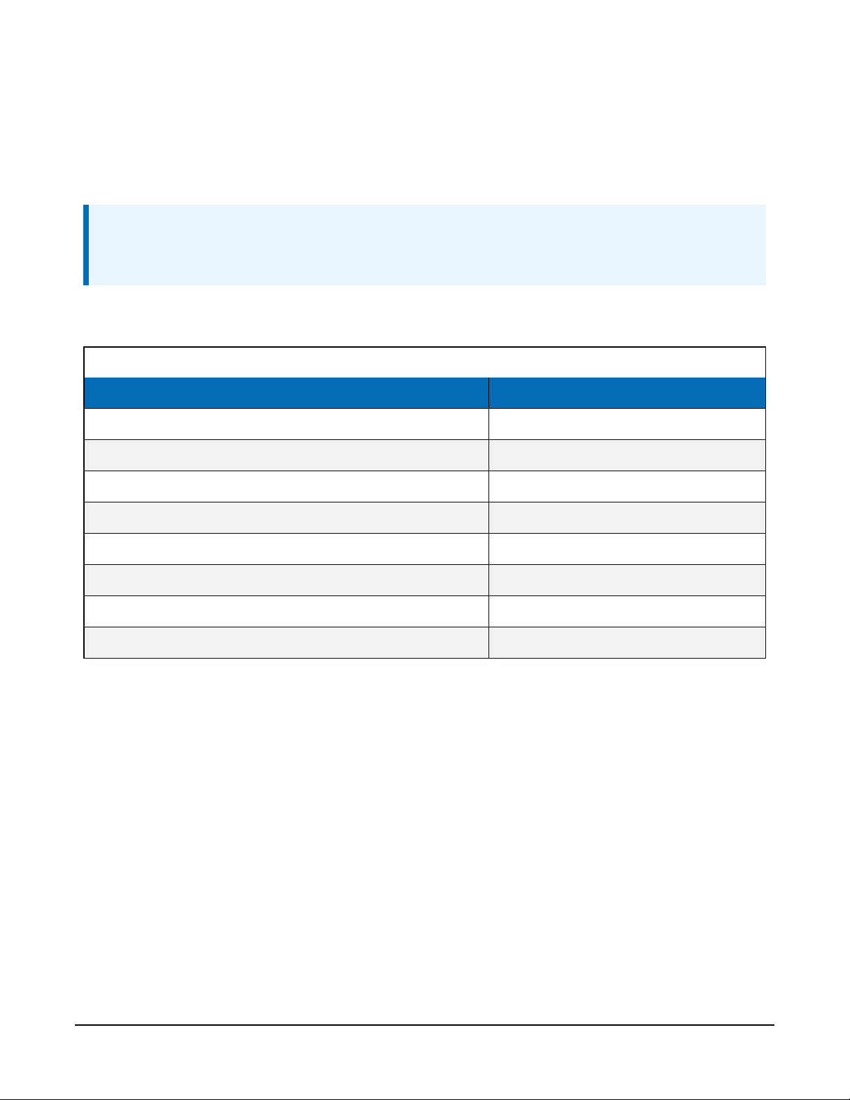
diminished (Table B-4 (p. 33)).
Table B-4: Pseudobinary ranges
Pseudobinary type Range
1-byte encoded unsigned integer 0 to +63
1-byte encoded signed integer –32 to +31
2-byte encoded unsigned integer 0 to +4094
2-byte encoded signed integer –2048 to +2047
3-byte encoded unsigned integer 0 to +262143
3-byte encoded signed integer –131072 to +131071
4-byte encoded unsigned integer 0 to +16777215
4-byte encoded signed integer –8388608 to +8388607
B.2.1 Campbell Scientific FP2 data
The FP2 data format uses 16 bits to represent a variable-precision floating point number. FP2 has
a total range of -7999 to 7999 and variable precision of 0.001 to 1. It also has the ability to signal
+/– INF and NAN, most commonly used to indicate a computational or measurement error.
Table B-5 (p. 34)) shows the numeric ranges and precision; Table B-6 (p. 34) describes the bits,
and Table B-7 (p. 34) provides bit usage in calculating a finished value.
TX325 Satellite Transmitter for GOES V2 33
Page 37
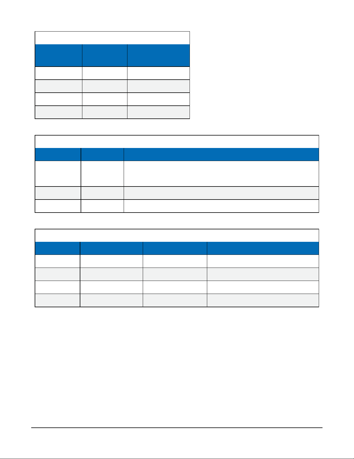
Table B-5: FP2 range and maximum precision
Range
Maximum
precision
–7.999 to 7.999 0.001 11
–79.99 to 79.99 0.01 10
–799.9 to 799.9 0.1 01
–7,999 to 7,999 1 00
Table B-6: Bit description
Name Bit Description
Sign (S) 16 (MSB)
Exponent (E) 15 and 14 Specifies the magnitude of the negative decimal exponent.
Mantissa (M) 13 to 0 (LSB) Specifies the magnitude of the 13-bit mantissa, 0 to 8191
b15 and b14
bit pattern
Specifies the sign of the value.
0 = positive, 1 = negative.
Table B-7: Calculation of finished value
Sign (S) Exponent (E) Mantissa (M) FP2 value equals
0 00 8191 + INF
1 00 8191 – INF
1 00 8190 NAN
0 or 1 00 or 01 or 10 0 to 7999 (–1 ^ S) × (10 ^ –E) × M
When transmitted in a pseudobinary format, the 16 bits are encoded as follows. Bits 16 through
13 are the least significant four bits of the first byte, bits 12 through 7 are the least significant six
bits of the second byte, and the last six bits are the least significant bits of the last byte. The
following tables are examples of encoding values.
TX325 Satellite Transmitter for GOES V2 34
Page 38
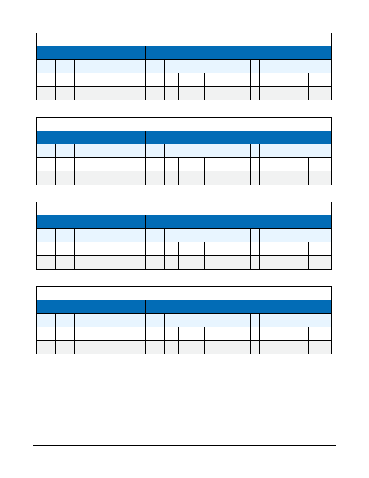
Table B-8: Encoding of 1234
Character 1 = @ Character 2 = S Character 3 = R
Sign Exponent Mantissa Mantissa Mantissa
p 1 0 0 b16 b15 b14 b13 p 1 b12 b11 b10 b9 b8 b7 p 1 b6 b5 b4 b3 b2 b1
0 1 0 0 0 0 0 0 0 1 0 1 0 0 1 1 0 1 0 1 0 0 1 0
Table B-9: Encoding of 1.234
Character 1 = F Character 2 = S Character 3 = R
Sign Exponent Mantissa Mantissa Mantissa
p 1 0 0 b16 b15 b14 b13 p 1 b12 b11 b10 b9 b8 b7 p 1 b6 b5 b4 b3 b2 b1
0 1 0 0 0 1 1 0 0 1 0 1 0 0 1 1 0 1 0 1 0 0 1 0
Table B-10: Encoding of 12.34
Character 1 = D Character 2 = S Character 3 = R
Sign Exponent Mantissa Mantissa Mantissa
p 1 0 0 b16 b15 b14 b13 p 1 b12 b11 b10 b9 b8 b7 p 1 b6 b5 b4 b3 b2 b1
0 1 0 0 0 1 0 0 0 1 0 1 0 0 1 1 0 1 0 1 0 0 1 0
Table B-11: Encoding of 123.4
Character 1 = B Character 2 = S Character 3 = R
Sign Exponent Mantissa Mantissa Mantissa
p 1 0 0 b16 b15 b14 b13 p 1 b12 b11 b10 b9 b8 b7 p 1 b6 b5 b4 b3 b2 b1
0 1 0 0 0 0 1 0 0 1 0 1 0 0 1 1 0 1 0 1 0 0 1 0
TX325 Satellite Transmitter for GOES V2 35
Page 39
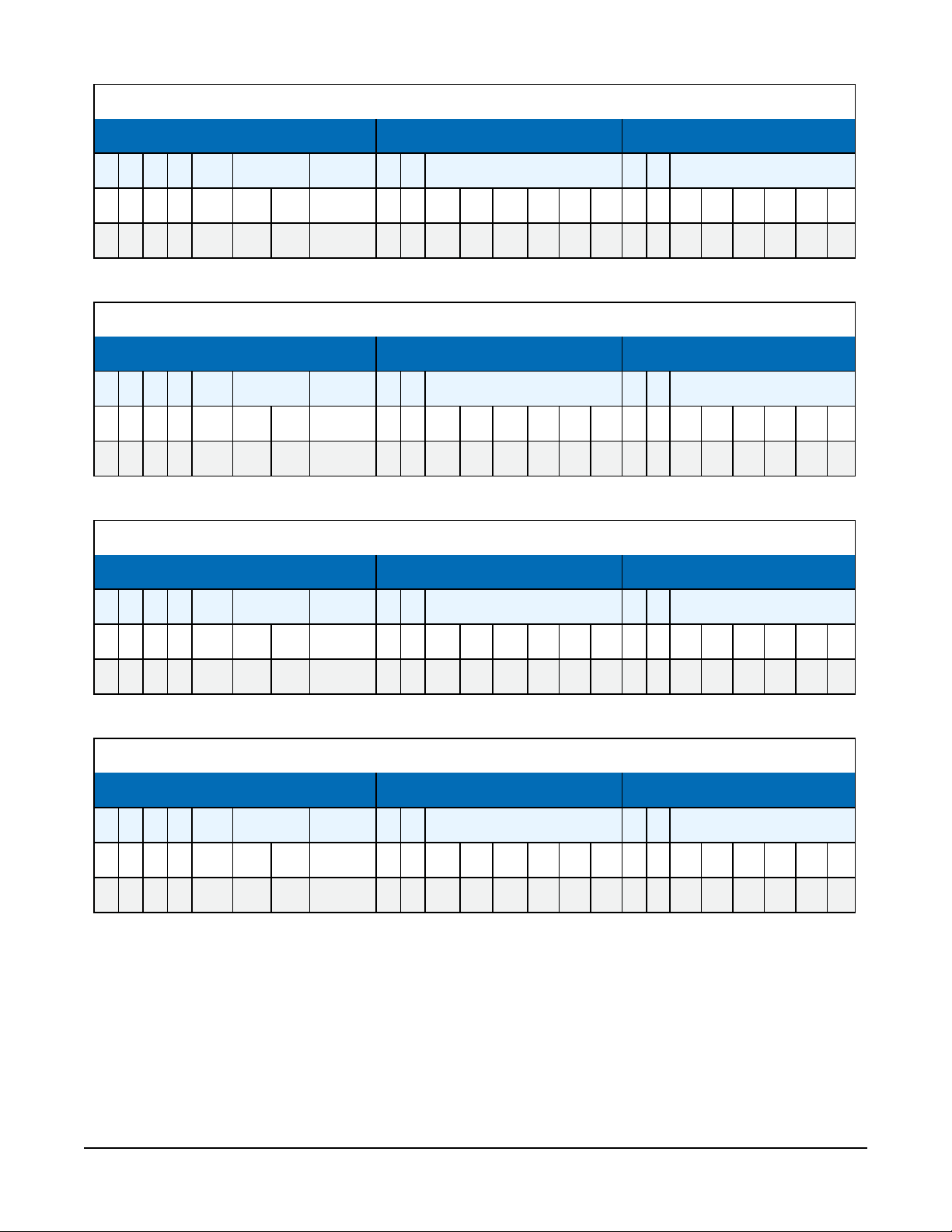
Table B-12: Encoding of 0.123
Character 1 = F Character 2 = A Character 3 = {
Sign Exponent Mantissa Mantissa Mantissa
p 1 0 0 b16 b15 b14 b13 p 1 b12 b11 b10 b9 b8 b7 p 1 b6 b5 b4 b3 b2 b1
0 1 0 0 0 1 1 0 0 1 0 0 0 0 0 1 0 1 1 1 1 0 1 1
Table B-13: Encoding of -1234
Character 1 = H Character 2 = S Character 3 = R
Sign Exponent Mantissa Mantissa Mantissa
p 1 0 0 b16 b15 b14 b13 p 1 b12 b11 b10 b9 b8 b7 p 1 b6 b5 b4 b3 b2 b1
0 1 0 0 1 0 0 0 0 1 0 1 0 0 1 1 0 1 0 1 0 0 1 0
Table B-14: Encoding of -1.234
Character 1 = N Character 2 = S Character 3 = R
Sign Exponent Mantissa Mantissa Mantissa
p 1 0 0 b16 b15 b14 b13 p 1 b12 b11 b10 b9 b8 b7 p 1 b6 b5 b4 b3 b2 b1
0 1 0 0 1 1 1 0 0 1 0 1 0 0 1 1 0 1 0 1 0 0 1 0
Table B-15: Encoding of -12.34
Character 1 = L Character 2 = S Character 3 = R
Sign Exponent Mantissa Mantissa Mantissa
p 1 0 0 b16 b15 b14 b13 p 1 b12 b11 b10 b9 b8 b7 p 1 b6 b5 b4 b3 b2 b1
0 1 0 0 1 1 0 0 0 1 0 1 0 0 1 1 0 1 0 1 0 0 1 0
TX325 Satellite Transmitter for GOES V2 36
Page 40
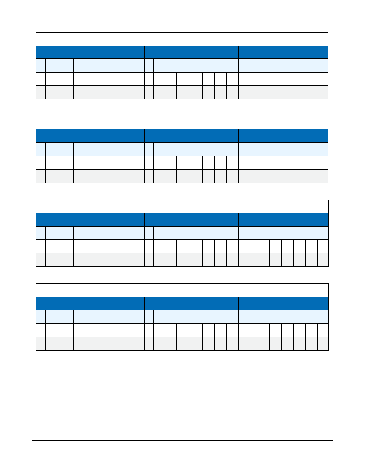
Table B-16: Encoding of -123.4
Character 1 = J Character 2 = S Character 3 = R
Sign Exponent Mantissa Mantissa Mantissa
p 1 0 0 b16 b15 b14 b13 p 1 b12 b11 b10 b9 b8 b7 p 1 b6 b5 b4 b3 b2 b1
0 1 0 0 1 0 1 0 0 1 0 1 0 0 1 1 0 1 0 1 0 0 1 0
Table B-17: Encoding of -0.123
Character 1 = N Character 2 = A Character 3 = {
Sign Exponent Mantissa Mantissa Mantissa
p 1 0 0 b16 b15 b14 b13 p 1 b12 b11 b10 b9 b8 b7 p 1 b6 b5 b4 b3 b2 b1
0 1 0 0 1 1 1 0 0 1 0 0 0 0 0 1 0 1 1 1 1 0 1 1
Table B-18: Encoding of INF
Character 1 = A Character 2 = ? Character 3 = ?
Sign Exponent Mantissa Mantissa Mantissa
p 1 0 0 b16 b15 b14 b13 p 1 b12 b11 b10 b9 b8 b7 p 1 b6 b5 b4 b3 b2 b1
0 1 0 0 0 0 0 1 0 0 1 1 1 1 1 1 0 0 1 1 1 1 1 1
Table B-19: Encoding of -INF
Character 1 = I Character 2 = ? Character 3 = ?
Sign Exponent Mantissa Mantissa Mantissa
p 1 0 0 b16 b15 b14 b13 p 1 b12 b11 b10 b9 b8 b7 p 1 b6 b5 b4 b3 b2 b1
0 1 0 0 1 0 0 1 0 0 1 1 1 1 1 1 0 0 1 1 1 1 1 1
TX325 Satellite Transmitter for GOES V2 37
Page 41
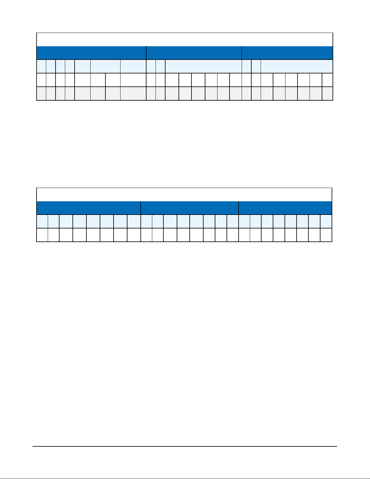
Table B-20: Encoding of NAN
Character 1 = I Character 2 = ? Character 3 = ~
Sign Exponent Mantissa Mantissa Mantissa
p 1 0 0 b16 b15 b14 b13 p 1 b12 b11 b10 b9 b8 b7 p 1 b6 b5 b4 b3 b2 b1
0 1 0 0 1 0 0 1 0 0 1 1 1 1 1 1 0 0 1 1 1 1 1 0
B.2.2 Pseudobinary
Pseudobinary or 18-bit integer data format is used to transmit a signed or unsigned integer. The
18 bits are encoded across 3 bytes. When signed, the value is encoded using a two-complement
representation. As an integer cannot directly represent a fractional number, measurements are
often scaled before storing to the GOES data table. For example, a water-level surface elevation
of 123.45 ft can be multiplied by 100 to get an integer of 12345. This integer is stored for
transmission with the encoding shown in Table B-21 (p. 38).
Table B-21: Example encoding of water level surface elevation value of 12345
Character 1 = C Character 2 = @ Character 3 = y
p 1 b18 b17 b16 b15 b14 b13 p 1 b12 b11 b10 b9 b8 b7 p 1 b6 b5 b4 b3 b2 b1
0 1 0 0 0 0 1 1 0 1 0 0 0 0 0 0 0 1 1 1 1 0 0 1
B.2.3 Additional pseudobinary representations
Other pseudobinary representations, such as 6, 12, and 24 bit integers, can be formed and
transmitted using CRBasic.
B.3 Transmission durations
Table B-22 (p. 39) provides the transmission durations, calculated from the number of bytes in a
message. Table B-23 (p. 39) provides the maximum data bytes for an assigned time slot duration.
TX325 Satellite Transmitter for GOES V2 38
Page 42
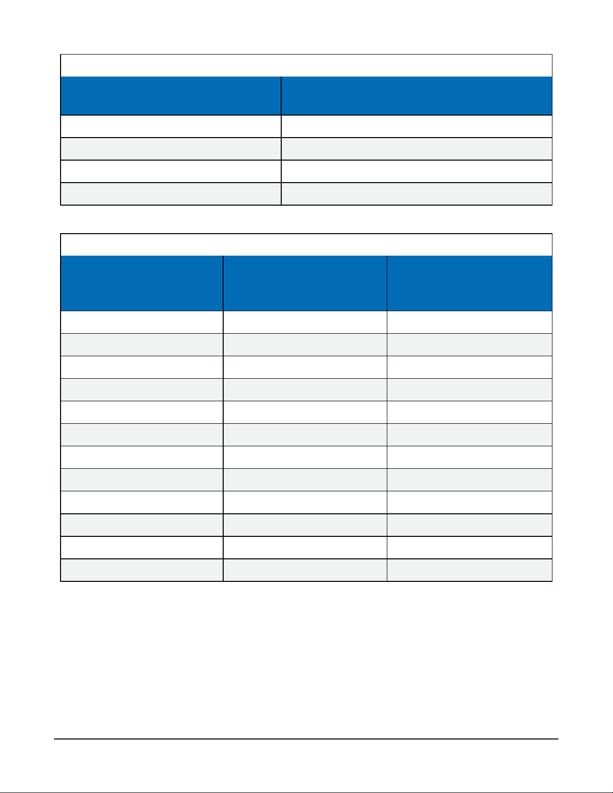
Table B-22: Calculating transmission duration for GOES 300/1200 bps messages
Transmit type
(where N = number of data bytes in a message)
Self-timed, 300 bps (137 + (N × 4))/150
Random, 300 bps (137 + (N × 4))/150
Self-timed, 1200 bps (223 + (N × 4))/600
Random, 1200 bps (223 + (N × 4))/600
Table B-23: GOES self-timed-message maximum data bytes and assigned time-slot duration
GOES 300 bps
Assigned time-slot
maximum data per message
duration (seconds)
(bytes)
5 153 694
10 340 1444
15 528 2194
Transmission duration (seconds)
GOES 1200 bps
maximum data per message
(bytes)
20 715 2944
25 903 3694
30 1090 4444
35 1278 5194
40 1465 5944
45 1653 6694
50 1840 7444
55 2028 8194
60 2215 8944
TX325 Satellite Transmitter for GOES V2 39
Page 43
Appendix C. Compliance
Certificate of Registration
This certifies that the Quality Management System of
Signal Engineering, Inc.
6370 Lusk Blvd., Suite F206
San Diego,, California, 92121, United States
has been assessed by NSF-ISR and found to be in conformance to the following standard(s):
ISO 9001:2015
Scope of Registration:
Engineering Design and Light Manufacturing of Electronic/Radio Communications Systems.
Carl Blazik,
Director, Technical
Operations & Business Units,
NSF-ISR, Ltd.
Certificate Number: C0195647-IS3
Certificate Issue Date: 24-APR-2018
Registration Date: 14-MAY-2017
Expiration Date *: 12-MAY-2020
documents and certificates
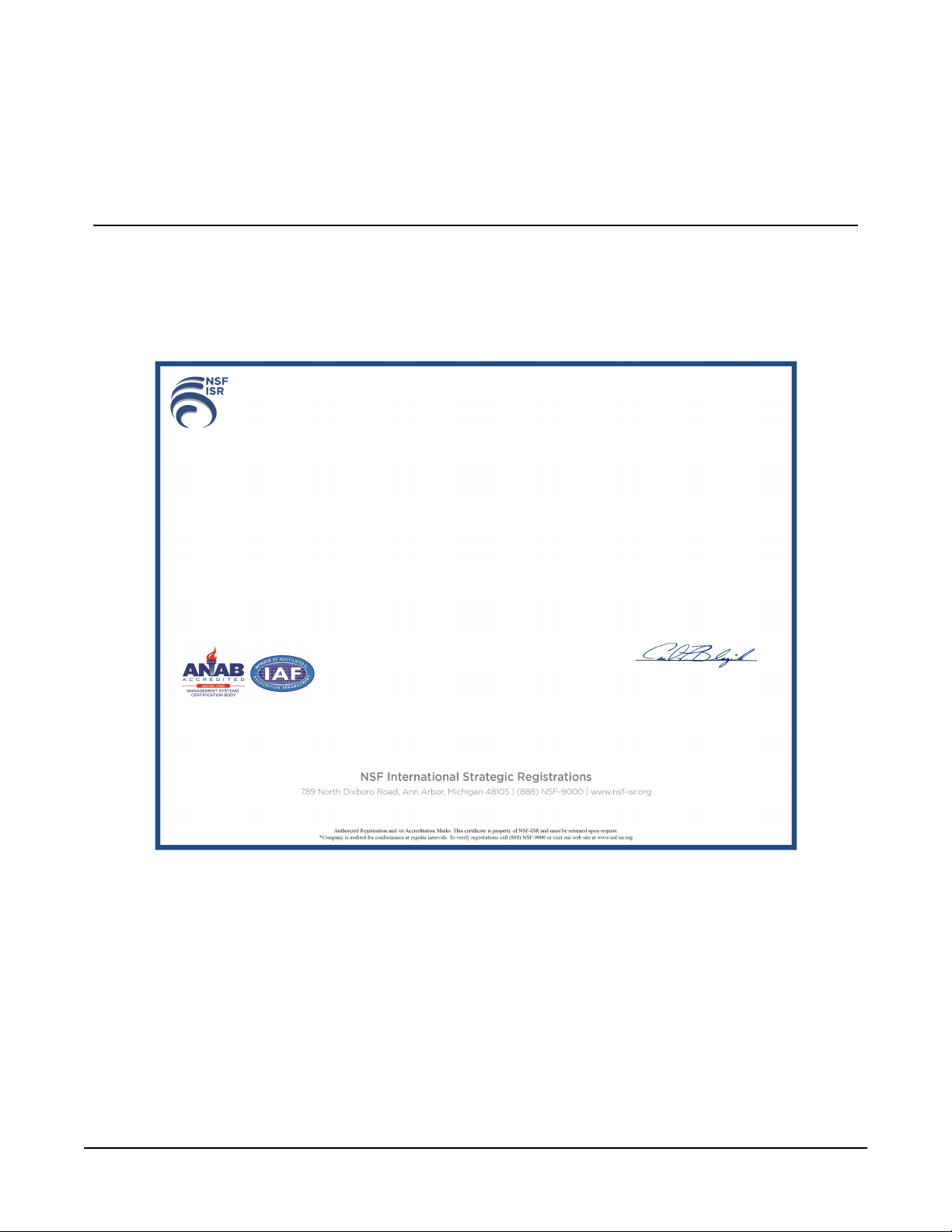
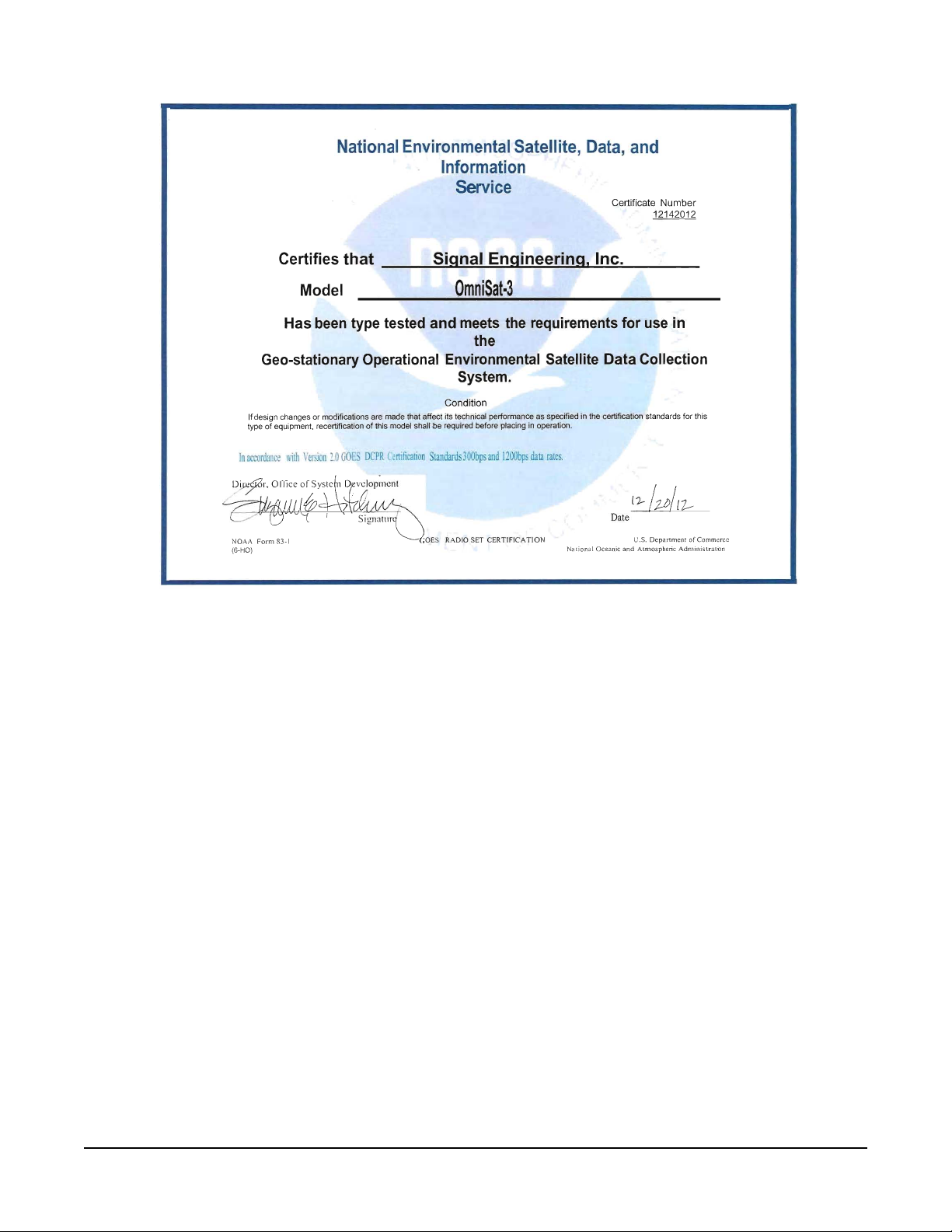
Compliance documents include the ISO certificate (FIGURE C-1 (p. 40)) and the GOES V2
certificate (FIGURE C-2 (p. 41)). The TX325 EU Declaration of Conformity is available at:
www.campbellsci.com/tx325.
FIGURE C-1. ISO certificate
TX325 Satellite Transmitter for GOES V2 40
Page 44
National
Environmental
Satellite,
Data,
and
Information
Service
Certificate
Number
12142012
Certifies that
Sianal Enaineerina. Inc.
Model
OmniSat·3
Has
been
type
tested
and
meets
the
requirements
for
use
in
the
Geo-stationary
Operational 'Environmental
Satellite
Data Collection
System.
Condition
Ifdesign changes or modifications are made that affect its technical performance as specified in the certification standards for this
type
of
equipment, recertification
of
this model shall be required before placing
in
operation.
In
accordance with
Ver5
ion
2.0 GOES
DCPR Certification
Standards
300bps
and
1200bps
data
rates
.
.
i>&
Ortice
of
Systc
1 D. '
vc/opmcnt
[)~7-r,
j I .
~
lJ-/
J-lJ/I2--
I~
~
"
Signature
Date
'
~
r/O
I
'.
' "\ .
IFICATIO
N
~
Ie( . .
010
SET CERT
A
Form
83-1
(;OEs
RA
LJ
.S.
Department
of
Commerce
NOA/
...
(6-HO)
Na
tiona I
Oceanic and Atmospheric
Administrati:l
n
FIGURE C-2. GOES V2 certificate
TX325 Satellite Transmitter for GOES V2 41
Page 45

Limited warranty
Products manufactured by Campbell Scientific are warranted by Campbell Scientific to be free
from defects in materials and workmanship under normal use and service for twelve months from
the date of shipment unless otherwise specified on the corresponding product webpage. See
Product Details on the Ordering Information pages at www.campbellsci.com. Other
manufacturer's products, that are resold by Campbell Scientific, are warranted only to the limits
extended by the original manufacturer.
Refer to www.campbellsci.com/terms#warranty for more information.
CAMPBELL SCIENTIFIC EXPRESSLY DISCLAIMS AND EXCLUDES ANY IMPLIED WARRANTIES OF
MERCHANTABILITY OR FITNESS FOR A PARTICULAR PURPOSE. Campbell Scientific hereby
disclaims, to the fullest extent allowed by applicable law, any and all warranties and conditions
with respect to the Products, whether express, implied or statutory, other than those expressly
provided herein.
Page 46

Assistance
Products may not be returned without prior authorization.
Products shipped to Campbell Scientific require a Returned Materials Authorization (RMA) or
Repair Reference number and must be clean and uncontaminated by harmful substances, such as
hazardous materials, chemicals, insects, and pests. Please complete the required forms prior to
shipping equipment.
Campbell Scientific regional offices handle repairs for customers within their territories. Please
see the back page for the Global Sales and Support Network or visit
www.campbellsci.com/contact to determine which Campbell Scientific office serves your country.
To obtain a Returned Materials Authorization or Repair Reference number, contact your
CAMPBELL SCIENTIFIC regional office. Please write the issued number clearly on the outside of
the shipping container and ship as directed.
For all returns, the customer must provide a “Statement of Product Cleanliness and
Decontamination” or “Declaration of Hazardous Material and Decontamination” form and
comply with the requirements specified in it. The form is available from your CAMPBELL
SCIENTIFIC regional office. Campbell Scientific is unable to process any returns until we receive
this statement. If the statement is not received within three days of product receipt or is
incomplete, the product will be returned to the customer at the customer’s expense. Campbell
Scientific reserves the right to refuse service on products that were exposed to contaminants that
may cause health or safety concerns for our employees.
Page 47

Safety
DANGER — MANY HAZARDS ARE ASSOCIATED WITH INSTALLING, USING, MAINTAINING, AND WORKING ON OR AROUND TRIPODS,
TOWERS, AND ANY ATTACHMENTS TO TRIPODS AND TOWERS SUCH AS SENSORS, CROSSARMS, ENCLOSURES, ANTENNAS, ETC. FAILURE
TO PROPERLY AND COMPLETELY ASSEMBLE, INSTALL, OPERATE, USE, AND MAINTAIN TRIPODS, TOWERS, AND ATTACHMENTS, AND
FAILURE TO HEED WARNINGS, INCREASES THE RISK OF DEATH, ACCIDENT, SERIOUS INJURY, PROPERTY DAMAGE, AND PRODUCT FAILURE.
TAKE ALL REASONABLE PRECAUTIONS TO AVOID THESE HAZARDS. CHECK WITH YOUR ORGANIZATION'S SAFETY COORDINATOR (OR
POLICY) FOR PROCEDURES AND REQUIRED PROTECTIVE EQUIPMENT PRIOR TO PERFORMING ANY WORK.
Use tripods, towers, and attachments to tripods and towers only for purposes for which they are designed. Do not exceed design limits. Be
familiar and comply with all instructions provided in product manuals. Manuals are available at www.campbellsci.com. You are responsible
for conformance with governing codes and regulations, including safety regulations, and the integrity and location of structures or land to
which towers, tripods, and any attachments are attached. Installation sites should be evaluated and approved by a qualified engineer. If
questions or concerns arise regarding installation, use, or maintenance of tripods, towers, attachments, or electrical connections, consult
with a licensed and qualified engineer or electrician.
General
l Protect from over-voltage.
l Protect electrical equipment from water.
l Protect from electrostatic discharge (ESD).
l Protect from lightning.
l Prior to performing site or installation work, obtain required approvals and permits. Comply with all governing structure-height
regulations.
l Use only qualified personnel for installation, use, and maintenance of tripods and towers, and any attachments to tripods and
towers. The use of licensed and qualified contractors is highly recommended.
l Read all applicable instructions carefully and understand procedures thoroughly before beginning work.
l Wear a hardhat and eye protection, and take other appropriate safety precautions while working on or around tripods and towers.
l Do not climb tripods or towers at any time, and prohibit climbing by other persons. Take reasonable precautions to secure tripod
and tower sites from trespassers.
l Use only manufacturer recommended parts, materials, and tools.
Utility and Electrical
l You can be killed or sustain serious bodily injury if the tripod, tower, or attachments you are installing, constructing, using, or
maintaining, or a tool, stake, or anchor, come in contact with overhead or underground utility lines.
l Maintain a distance of at least one-and-one-half times structure height, 6 meters (20 feet), or the distance required by applicable
law, whichever is greater, between overhead utility lines and the structure (tripod, tower, attachments, or tools).
l Prior to performing site or installation work, inform all utility companies and have all underground utilities marked.
l Comply with all electrical codes. Electrical equipment and related grounding devices should be installed by a licensed and qualified
electrician.
l Only use power sources approved for use in the country of installation to power Campbell Scientific devices.
Elevated Work and Weather
l Exercise extreme caution when performing elevated work.
l Use appropriate equipment and safety practices.
l During installation and maintenance, keep tower and tripod sites clear of un-trained or non-essential personnel. Take precautions to
prevent elevated tools and objects from dropping.
l Do not perform any work in inclement weather, including wind, rain, snow, lightning, etc.
Maintenance
l Periodically (at least yearly) check for wear and damage, including corrosion, stress cracks, frayed cables, loose cable clamps, cable
tightness, etc. and take necessary corrective actions.
l Periodically (at least yearly) check electrical ground connections.
Internal Battery
l Be aware of fire, explosion, and severe-burn hazards.
l Misuse or improper installation of the internal lithium battery can cause severe injury.
l Do not recharge, disassemble, heat above 100 °C (212 °F), solder directly to the cell, incinerate, or expose contents to water. Dispose
of spent batteries properly.
WHILE EVERY ATTEMPT IS MADE TO EMBODY THE HIGHEST DEGREE OF SAFETY IN ALL CAMPBELL SCIENTIFIC PRODUCTS, THE CUSTOMER
ASSUMES ALL RISK FROM ANY INJURY RESULTING FROM IMPROPER INSTALLATION, USE, OR MAINTENANCE OF TRIPODS, TOWERS, OR
ATTACHMENTS TO TRIPODS AND TOWERS SUCH AS SENSORS, CROSSARMS, ENCLOSURES, ANTENNAS, ETC.
Page 48
Campbell Scientific regional offices
Australia
Location:
Phone:
Email:
Website:
Brazil
Location:
Phone:
Email:
Website:
Canada
Location:
Phone:
Email:
Website:
China
Location:
Phone:
Email:
Website:
Garbutt, QLD Australia
61.7.4401.7700
[email protected]
www.campbellsci.com.au
São Paulo, SP Brazil
11.3732.3399
[email protected]
www.campbellsci.com.br
Edmonton, AB Canada
780.454.2505
[email protected]
www.campbellsci.ca
Beijing, P. R. China
86.10.6561.0080
[email protected]
www.campbellsci.com.cn
France
Location:
Phone:
Email:
Website:
Germany
Location:
Phone:
Email:
Website:
India
Location:
Phone:
Email:
Website:
South Africa
Location:
Phone:
Email:
Website:
Vincennes, France
0033.0.1.56.45.15.20
[email protected]
www.campbellsci.fr
Bremen, Germany
49.0.421.460974.0
[email protected]
www.campbellsci.de
New Delhi, DL India
91.11.46500481.482
[email protected]
www.campbellsci.in
Stellenbosch, South Africa
27.21.8809960
[email protected]
www.campbellsci.co.za
Thailand
Location:
Phone:
Email:
Website:
UK
Location:
Phone:
Email:
Website:
USA
Location:
Phone:
Email:
Website:
Bangkok, Thailand
66.2.719.3399
[email protected]
www.campbellsci.asia
Shepshed, Loughborough,
UK
44.0.1509.601141
[email protected]
www.campbellsci.co.uk
Logan, UT USA
435.227.9120
[email protected]
www.campbellsci.com
Costa Rica
Location:
Phone:
Email:
Website:
San Pedro, Costa Rica
506.2280.1564
[email protected]
www.campbellsci.cc
Spain
Location:
Phone:
Email:
Website:
Barcelona, Spain
34.93.2323938
[email protected]
www.campbellsci.es
 Loading...