

Camille Bauer SIRAX MM1400 Operating Instructions Manual

Device handbook
SIRAX MM1400
Operating Instructions SIRAX MM1400
Camille Bauer Metrawatt AG
Aargauerstrasse 7
CH-5610 Wohlen/Switzerland
Tel: +41 56 618 21 11
Fax: +41 56 618 21 21
info@cbmag.com
www.camillebauer.com

PM 1000269 000 02 Device handbook SIRAX MM1400 2/60
Legal information
Warning notices
In this document warning notices are used, which you have to observe to ensure personal safety and to prevent damage to property. Depending
on the degree of danger the following symbols are used:
Qualified personnel
The product described in this document may be handled by personnel only, which is qualified for the respective task. Qualified personnel have
the training and experience to identify risks and potential hazards when working with the product. Qualified personnel are also able to understand
and follow the given safety and warning notices.
Intended use
The product described in this document may be used only for the application specified. The maximum electrical supply data and ambient conditions specified in the technical data section must be adhered. For the perfect and safe operation of the device proper transport and storage as
well as professional assembly, installation, handling and maintenance are required.
Disclaimer of liability
The content of this document has been reviewed to ensure correctness. Nevertheless it may contain errors or inconsistencies and we cannot
guarantee completeness and correctness. This is especially true for dierent language versions of this document. This document is regularly
reviewed and updated. Necessary corrections will be included in subsequent version and are available via our webpage www.camillebauer.com.
Feedback
If you detect errors in this document or if there is necessary information missing, please inform us via e-mail to:
customer-support@camillebauer.com
If the warning notice is not followed death or severe personal injury will result.
If the warning notice is not followed damage to property or severe personal injury may result.
If the warning notice is not followed the device may be damaged or may not fulfill the expected
functionality.

PM 1000269 000 02 Device handbook SIRAX MM1400 3/60
Table of contents
1. Introduction ………………………………………………………………………………………………… 5
1.1 Purpose of this document ………………………………………………………………………………………… 5
1.2 Scope of supply ………………………………………………………………………………………………… 5
1.3 Further documents ……………………………………………………………………………………………… 5
2. Safety notes ………………………………………………………………………………………………… 5
3. Device overview ………………………………………………………………………………………………… 6
3.1 Brief description ………………………………………………………………………………………………… 6
3.2 Available measurement data ……………………………………………………………………………………… 6
4. Mechanical mounting ……………………………………………………………………………………………… 7
4.1 Panel cut out ………………………………………………………………………………………………… 7
4.2 Mounting of the device …………………………………………………………………………………………… 7
4.3 Demounting of the device ………………………………………………………………………………………… 7
5. Electrical connections ……………………………………………………………………………………………… 8
5.1 General safety notes …………………………………………………………………………………………… 8
5.2 Possible cross sections and tightening torques …………………………………………………………………… 8
5.3 Inputs ………………………………………………………………………………………………… 9
5.4 Power supply ………………………………………………………………………………………………… 10
5.5 Modbus interface RS485 ………………………………………………………………………………………… 10
6. Commissioning ………………………………………………………………………………………………… 10
6.1 Operating the device ………………………………………………………………………………………… 11
6.2 Measurement Reading Screens …………………………………………………………………………………… 11
6.3 Measurement Parameter Screen ………………………………………………………………………………… 11
6.4 Setup Parameter Screen ………………………………………………………………………………………… 12
7. Programming ………………………………………………………………………………………………… 13
7.1. Password Protection …………………………………………………………………………………………… 13
7.1.1. Change Password ………………………………………………………………………………………… 14
7.2. Menu selection ………………………………………………………………………………………………… 14
7.2.1 System Parameters Selection ……………………………………………………………………………… 14
7.2.1.1. System Type ………………………………………………………………………………………… 15
7.2.1.2. Potential Transformer Primary Value …………………………………………………………………… 15
7.2.1.3 Potential Transformer secondary Value ………………………………………………………………… 15
7.2.1.4 Current Transformer Primary Value …………………………………………………………………… 16
7.2.1.5 Current Transformer Secondary Value ………………………………………………………………… 16
7.2.1.6 Demand Integration Time …………………………………………………………………………… 17
7.2.1.7 Energy update rate …………………………………………………………………………………… 17
7.2.1.8 Low Current noise cuto. ……………………………………………………………………………… 17
7.2.1.9 ENERGY RESOLUTION ………………………………………………………………………………… 17
7.2.1.10 ENERGY DIGIT RESET COUNT (ROLLOVER COUNT) …………………………………………………… 18
7.2.2 Communication Parameter Selection ……………………………………………………………………… 18
7.2.2.1 RS485 Address Setting ……………………………………………………………………………… 18
7.2.2.2 RS 485 Baud Rate …………………………………………………………………………………… 19
7.2.2.3 RS 485 Parity & Stop bit Selection …………………………………………………………………… 19
7.2.3 Reset Parameter Selection ………………………………………………………………………………… 19
7.2.3.1 Resetting Parameter ………………………………………………………………………………… 19
7.2.4 Time Of Day Setup …………………………………………………………………………………… 20
7.2.4.1 Weekends selection ……………………………………………………………………………… 21
7.2.4.2 Holidays selection ………………………………………………………………………………… 21
7.2.4.3 Alternate days selection …………………………………………………………………………… 21
7.2.4.4 Profiles ………………………………………………………………………………………… 21
7.2.4.5 Seasons ………………………………………………………………………………………… 21
7.2.4.6 Timezones ……………………………………………………………………………………… 22
7.2.4.7 Weekdays / Weekends / Holidays / Alternate days Timezones ……………………………………… 22
7.2.5 Power Quality Setup …………………………………………………………………………………… 22
7.2.5.1 Threshold Setup ………………………………………………………………………………… 22
7.2.5.2 Harmonics Setup ………………………………………………………………………………… 23
7.2.6 Clock Setup …………………………………………………………………………………………… 23
7.2.7 Brightness & Contrast ………………………………………………………………………………… 23
7.2.8 RGB Color Code ……………………………………………………………………………………… 24

PM 1000269 000 02 Device handbook SIRAX MM1400 4/60
8. Touch screen calibration …………………………………………………………………………………………… 24
9. Phase Rotation Error screen ……………………………………………………………………………………… 25
10. Run Hour ………………………………………………………………………………………………… 26
11. On Hour ………………………………………………………………………………………………… 26
12. Number of Interruption …………………………………………………………………………………………… 26
13. Phasor Diagram ………………………………………………………………………………………………… 27
14. Service, maintenance and disposal ……………………………………………………………………………… 28
14.1 Repair work and modifications ………………………………………………………………………………… 28
14.2 Calibration and new adjustment ………………………………………………………………………………… 28
14.3 Cleaning ………………………………………………………………………………………………… 28
14.4 Disposal ………………………………………………………………………………………………… 28
14.5 Return ………………………………………………………………………………………………… 28
15. Technical data ………………………………………………………………………………………………… 29
15.1 Dimensional drawings ………………………………………………………………………………………… 31
16. Interface Definition Modbus (RS485) ……………………………………………………………………………… 32
16.1 Accessing 3 X register for reading measured values ……………………………………………………………… 32
16.2 Accessing Sag, Swell, Over Current data through MODBUS ……………………………………………………… 39
16.3 Accessing 3 X for reading Time Of Day data …………………………………………………………………… 43
16.4 Accessing TOD Zone wise Data of Last 31 days ………………………………………………………………… 47
16.5 Accessing 4 X register for reading & Writing ……………………………………………………………………… 49
16.6 User Assignable Modbus Register ……………………………………………………………………………… 56
16.7 Connections ………………………………………………………………………………………………… 58
PM 1000269 000 02 Device handbook SIRAX MM1400 5/60
1. Introduction
1.1 Purpose of this document
This document describes the universal measurement device SIRAX MM1400. It is intended to be used by:
•
Installation personnel and commissioning engineers
•
Service and maintenance personnel
•
Planners
Scope
This handbook is valid for all hardware versions of the MM1400. Some of the functions described in this doc-ument are available only, if the
necessary optional components are included in the device.
Required knowledge
A general knowledge in the field of electrical engineering is required. For assembly and installation of the device knowledge of applicable national
safety regulations and installation standard is required.
1.2 Scope of supply
•
Measurement device SIRAX MM1400
•
Safety instructions (multiple languages)
•
Connection set: 4 mounting clamps
1.3 Further documents
The following documents are provided electronically via www.camillebauer.com:
•
Safety instructions SIRAX MM1400
•
Operating Instructions SIRAX MM1400
2. Safety notes
Device may only be disposed in a professional manner!
The installation and commissioning should only be carried out by trained personnel.
Check the following points before commissioning:
- that the maximum values for all the connections are not exceeded, see „Technical data“ section,
- that the connection wires are not damaged, and that they are not live during wiring,
- that the power flow direction and the phase rotation are correct.
The instrument must be taken out of service if safe operation is no longer possible (e.g. visible damage). In this
case, all the connections must be switched o. The instrument must be returned to the factory or to an authorized
service dealer.
It is forbidden to open the housing and to make modifications to the instrument. The instrument is not equipped
with an integrated circuit breaker. During installation check that a labeled switch is installed and that it can easily
be reached by the operators.
Unauthorized repair or alteration of the unit invalidates the warranty.

PM 1000269 000 02 Device handbook SIRAX MM1400 6/60
3. Device overview
3.1 Brief description
The universal measuring device SIRAX MM1400 is suited for fixed mounting and the measurement of Voltage, current, frequency, power, energy
(active / reactive / apparent), power factor, phase angle, etc in low voltage switchgear. The units are designed for unbalanced load network forms
of 3-phase mains with 3- or 4-wire.
3.2 Available measurement data
Measured Parameters Units 3P 3W 3P 4W
System Voltage V • •
Voltage UL1-N / UL2-N / UL3-N V – •
Voltage UL1-2 / UL2-3 / UL3-1 V • •
System Current A • •
Current IL1 / IL2 / IL3 A • •
Neutral Current A – •
Frequency Hz • •
Active Power kW – •
Reactive Power kVAr – •
Apparent Power kVA – •
Power Factor – – •
Phase Angle degree – •
Active Import Energy (8 Digit resolution)* kWh • •
Active Export Energy (8 Digit resolution)* kWh • •
Reactive Import Energy (8 Digit resolution)* kVArh • •
Reactive Export Energy (8 Digit resolution)* kVArh • •
Apparent Energy (8 Digit resolution)* kVAh • •
Current Demand A • •
Max Current Demand A • •
Apparent Power Demand kVA • •
Max Apparent Power Demand kVA • •
Import Active Power Demand kW • •
Export Active Power Demand kW • •
Max Import Active Power Demand kW • •
Max Export Active Power Demand kW • •
Run Hour hours • •
On Hour hours • •
Number of Interruptions counts • •
Phase Rotation Error – – •
Phase Absent Indication – – •
Voltage THD U1/U2/U3* % • •
Current THD I1/I2/I3* % • •
Min / Max System Voltage V – •
Min / Max System Current A – •
Phase Diagram (only 4 wire) – – •
Voltage Waveform – • •
Current Waveform – • •
Waveform per phase – – •
* THD Parameters are L-N in case of 3P 4W & L-L in case of 3P 3W
PM 1000269 000 02 Device handbook SIRAX MM1400 7/60
4. Mechanical mounting
The SIRAX MM1400 is designed for panel mounting.
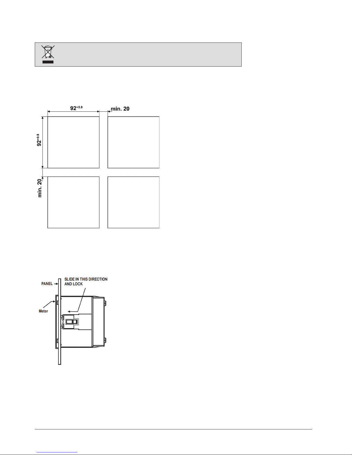
4.1 Panel cut out
Dimensional drawing MM1400: See section 16.1
4.2 Mounting of the device
The device is suitable for panel widths up to 5mm and a panel cutout of 96 x 96 mm.
Variant with Mounting clamps
a) Slide the device into the cutout from the outside
b) Mounting is by four side clamps, slide the side clamps through
side slot till side clamp gets firmly locked in a groove (Refer fig.)
Consideration should be given to the space required behind the
instrument to allow for bends in the connection cables.
4.3 Demounting of the device
The demounting of the device may be performed only if all connected wires are out of service. Remove all plug-in terminals and all connections
of the current and voltage inputs. Pay attention to the fact, that current transformers must be shortened before removing the current connections
to the device. Then demount the device in the opposite order of mounting (4.2).
Please ensure that the operating temperature limits are not exceeded when determining
the place of mounting (place of measurement): –10 … +55° C
PM 1000269 000 02 Device handbook SIRAX MM1400 8/60
5. Electrical connections
Ensure under all circumstances that the leads are free of potential when
connecting them!
Please observe that the data on the type plate must be adhered to!
The national provisions have to be observed in the installation and material selection of
electric lines!
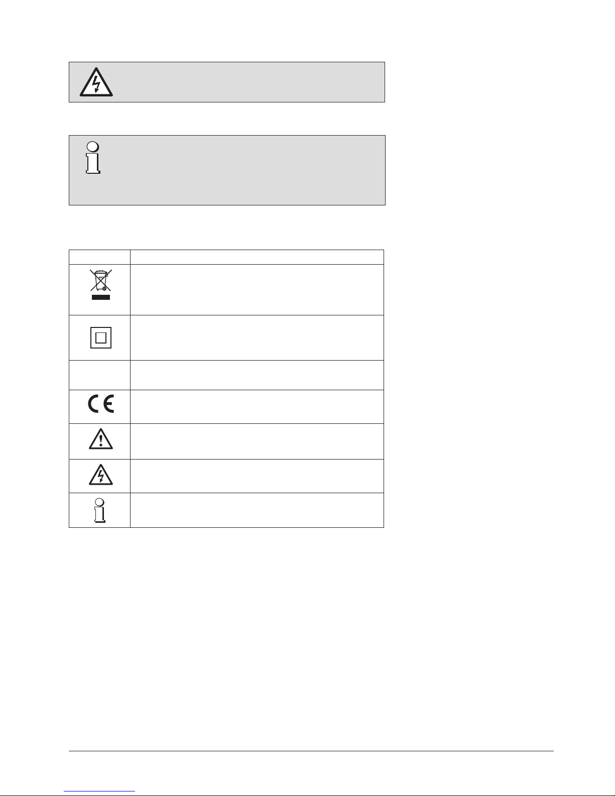
5.1 General safety notes
Symbol Meaning
Device may only be disposed of in a professional manner!
Double insulation, device of protection class 2
CAT III
Measurement category CAT III for current / voltage inputs, power supply
and relay outputs
CE conformity mark. The device fulfills the requirements of the applicable
EC directives. See declaration of conformity.
Caution! General hazard point. Read the operating instructions.
Attention: Danger to life!
Please note
5.2 Possible cross sections and tightening torques
Inputs L1(2), L2(5), L3(8), N(11), I1(1-3), I2(4-6), I3(7-9), power supply (13-14), RS485 connector (A/B/G)
Single wire: 1 x 0,5 … 4,0mm2 oder 2 x 0,5 … 2,5mm2
Multiwire with end splices: 1 x 0,5 … 4,0mm2 oder 2 x 0,5 … 2,5mm2
Tightening torque
0,5 … 0,6 Nm resp. 4,42 … 5,31 lbf in
PM 1000269 000 02 Device handbook SIRAX MM1400 9/60
All voltage measurement inputs must originate at circuit breakers or fuses rated by 1 Amps. This
does not apply to the neutral connector. You have to provide a method for manually removing
power from the device, such as a clearly labeled circuit breaker or a fused disconnect switch.
When using voltage transformers you have to ensure that their secondary connections never will be
short-circuited.
No fuse may be connected upstream of the current measurement inputs!
When using current transformers their secondary connectors must be short-circuited during
installation and before removing the device. Never open the secondary circuit under load.
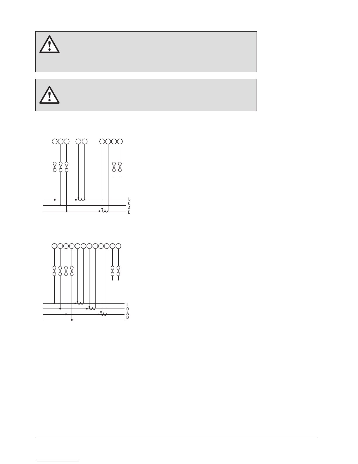
The connection of the inputs depends on the configured system (connection type).
Three Phase - three wire system, unbalanced load
2
L1
L N
AUX
SUPPLY
P1P1S1
S1
L2
L3
1 3 7 9 13 145 8
LOAD
Three Phase - four wire system, unbalanced load
2
L1
L N
AUX
SUPPLY
P1P1S1
S1
L2
L3
N
1 3 7 9 13 145 8
LOAD
11
P1 S1
4 6
5.3 Inputs
Direct connection
Direct connection
PM 1000269 000 02 Device handbook SIRAX MM1400 10/60
5.4 Power supply
A marked and easily accessible current limiting switch has to be arranged in the vicinity of the
device for turning o the power supply. Fusing should be 10 Amps or less and must be rated for
the available voltage and fault current.
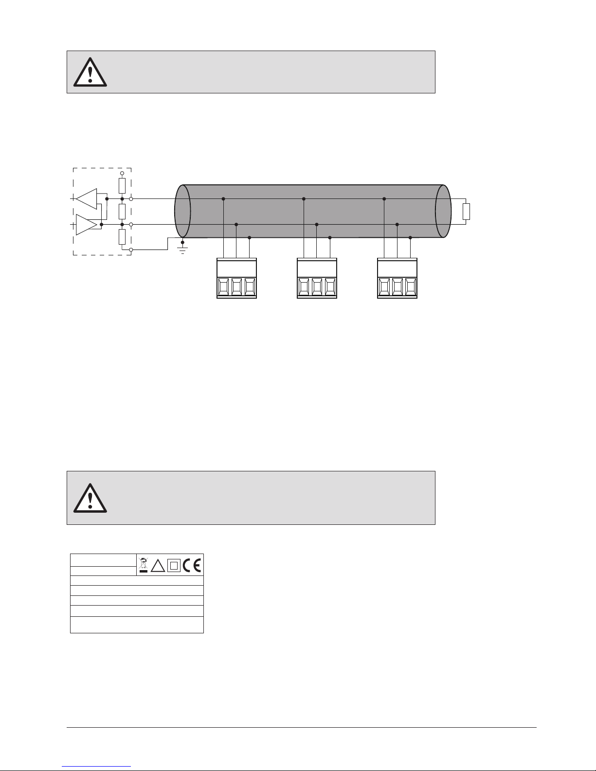
5.5 Modbus interface RS485
Via the optional Modbus interface measurement data may be provided for a superior system.
MASTER
+3.3 / +5V
Rx/Tx+,A
RS485 Bus
Rs
Rt
Rs
Rx/Tx-,B
GND
1)
Rt
A B G A B G A B G
The signal wires (A, B) have to be twisted. GND (G) can be connected via a wire or via the cable screen. In disturbed environments shielded
cables must be used. Supply resistors (Rs) have to be present in bus master (PC) interface. Stubs should be avoided when connecting the
devices. A pure daisy chain network is ideal.
You may connect up to 32 Modbus devices to the bus. A proper operation requires that all devices connected to the bus have equal
communication settings (baud rate, transmission format) and unique Modbus addresses.
The bus system is operated half duplex and may be extended to a maximum length of 1200 m without repeater.
6. Commissioning
Before commissioning you have to check if the connection data of the device match the data of
the plant.
If so, you can start to put the device into operation by switching on the power supply and the
measurement inputs.
1) One ground connection only. This is
possibly made within the master
(PC).
Rt: Termination resistors: 120 Ω each for
long cables (> approx. 10 m)
Rs: Bus supply resistors,
390 Ω each
ORDER CODE: 175093
SR No.: 15/11/0001
SIRAX MM1400
AUXILIARY: 60...300V AC/DC, 6.5VA
CLASS: 0.5s
INPUT: 3PH. 500 V L - L, 5A/1A, 45...66Hz
CAT III 300V Max.
V1.12
OPTION: RS485
IMPULSE: 4000 imp/KWh
!
Label version standard
PM 1000269 000 02 Device handbook SIRAX MM1400 11/60
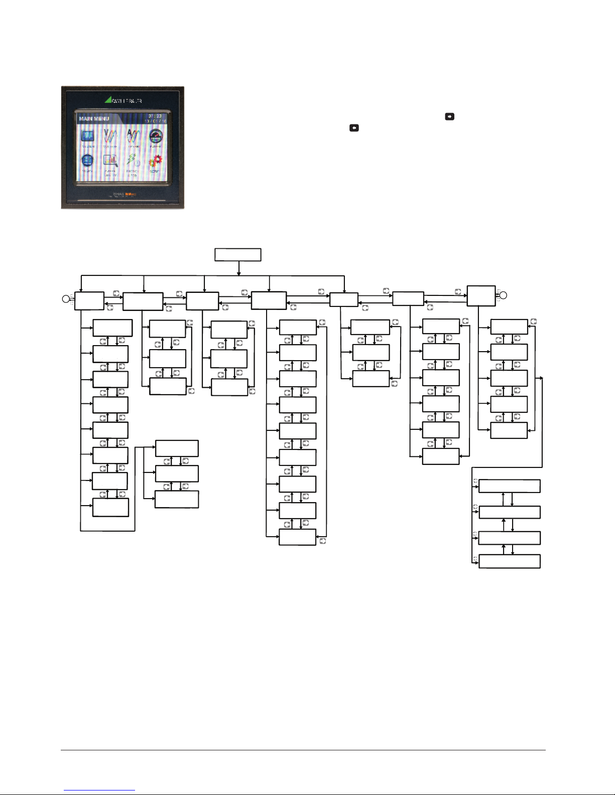
6.1 Operating the device
6.2 Measurement Reading Screens
6.3 Measurement Parameter Screen
Harmonic Analyse: When this option is selected from Power Quality
menu, meter shows the graphical analysis of the harmonics selected
in Setup --> Power Quality Setup --> Harmonic Setup L1/L2/L3.
Harmonics are plotted considering fundamental as 100 %. When
particular bar is touched, further details of that particular harmonic
/ fundamental are show. User can view RMS values of voltage and
current, voltage & current harmonic distortion %, kW / kVAR / kVA /
PF (in 3p 4w only) of that selected harmonic by using side arrow keys.
SAG / Swell / Over Current: These screens show the nos of sag /
swell / over current that instrument has detected with the timestamp
of arrival of events. Instrument stores the log of up to 30 events on
FIFO basis.
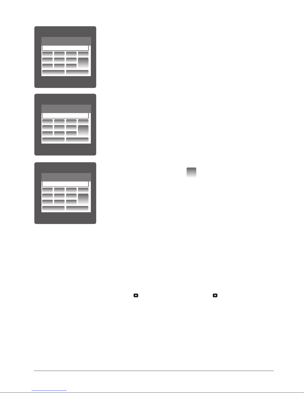
Energy and TOD:
Daily report: This screens shows the zone wise energy, its applicable
tari rate & cost of that zone in table format. The total energy accumulated for current day and related cost is also show.
Date wise Analysis: This screen shows the graphical trend of per
date energy. Up to last 30 days data is shown. By touching on the bar,
energy and cost of that date can be seen.
Month wise Analysis: This screen shows the graphical trend of per
month energy. Up to last 12 months data is shown. By touching on the
bar in graph, energy and cost of that month can be seen.
MAIN MENU
SYSTEM
A
VOLTAGE
CURRENT
POWER
SCOPE
ENERGY
& TOD
POWER
QUALITY
SYSTEM
PARAMETERS
Line to Neutral*
VOLTAGE
Line to Line
VOLTAGE
VOLTAGE
% THD
Line Current
L1 PHASE
POWER *
VOLTAGE
WAVEFORM
PHASE
VOLTAGE % THD
LINE
CURRENT % THD
HARMONIC
ANALYSIS
VOLTAGE
SAG
ACTIVE ENERGY
IMPORT
APPARENT
ENERGY
ACTIVE ENERGY
EXPORT
REACTIVE ENERGY
EXPORT
REACTIVE ENERGY
IMPORT
VOLTAGE
SWELL
OVER
CURRENT
CURRENT
WAVEFORM
PHASOR *
WAVEFORM
L2 PHASE
POWER *
L3 PHASE
POWER *
PHASE
ANGLE *
KWh/KVArh/KVA
TOD DAILY REPORT
TOD DATEWISE ANALYSIS
TOD MONTH WISE ANALYSIS
CURRENT
DEMAND
VA
DEMAND
IMPORT
ACTIVE DEMAND
EXPORT
ACTIVE DEMAND
PHASE
POWER FACTOR*
Neutral
Current *
LINE CURRENT
% THD
SYSTEM
POWER
SYSTEM
FREQUENCY
SYSTEM
MAX. VALUES
SYSTEM
MIN. VALUES
RUN HOUR
ON HOUR
NOTE: Screens marked with * are available only
in 4W System (not in 3 wire system)
SYSTEM
POWER FACTOR
SYSTEM
INTERRUPTIONS
THD. VOLTAGE
AND CURRENT
PHASE *
SEQUENCE
A
In normal operation the user is presented with one of the measurement reading
screens out of several screens. These screens from particular submenu may be
scrolled through one at a time in incremental order by touching the “ key”
and in decremental order by touching “ key” on that screen. Viewing of any
individual parameter with large reading (eg. shown of Line to neutral Voltage L2 in
sub menu 2 screen 13) is also possible by touching that particular parameter.
PM 1000269 000 02 Device handbook SIRAX MM1400 12/60
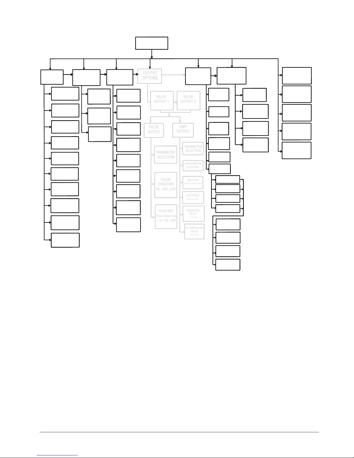
6.4 Setup Parameter Screen
PASSWORD
SYSTEM
PARAMETERS
(Sec. 7.2.1)
SYSTEM TYPE
(Sec. 7.2.1.1)
PT PRIMARY
(Sec. 7.2.1.2)
PT SECONDARY
(Sec. 7.2.1.3)
CT PRIMARY
(Sec. 7.2.1.4)
DEMAND
INTEGRATION TIME
(Sec. 7.2.1.6)
ENERGY
UPDATE RATE
(Sec. 7.2.1.7)
LOW CURR.
NOISE CUTOFF
(Sec. 7.2.1.8)
ENERGY
RESOLUTION
(Sec. 7.2.1.9)
ENERGY DIGIT
RESET COUNT
(Sec. 7.2.1.10)
CT SECONDARY
(Sec. 7.2.1.5)
COMMUNICATION
PARAMETERS
(Sec. 7.2.2)
RESET
PARAMETERS
(Sec. 7.2.3)
TIME OF
DAY SETUP
(Sec. 7.2.5)
POWER QUALITY
SETUP
(Sec. 7.2.5)
(Sec. 7.1)
ENTER
RS485
ADDRESS
(Sec. 7.2.2.1)
OUTPUT
OPTIONS
RELAY
OUTPUT 1
PULSE
OUTPUT
PARAMETER
SELECTION
PARAMETER
SELECTION
CONFIGURATION
SELECTION
TRIP POINT
10% to 100%/120%
HYSTERESIS
0.5% to 50%
ENERGIZING
DELAY
1s to 10s
DE-ENERGIZING
DELAY
1s to 10s
PULSE
DURATION
60, 100, 200
PULSE RATE
(Pulse Divisor rate)
1, 10, 100, 1000
LIMIT
OUTPUT
RELAY
OUTPUT 2
WEEKENDS
(Sec. 7.2.4.1)
THRESHOLD
SETUP
(Sec. 7.2.5.1)
CHANGE
PASSWORD
(Sec. 7.1.1)
CLOCK
SETUP
(Sec. 7.2.6)
BRIGHTNESS
&
CONTRAST
(Sec. 7.2.7)
FACTORY
RESTORE
RGB
CODE
(Sec. 7.2.8)
HARMONICS
SETUP L2
(Sec. 7.2.5.2)
HARMONICS
SETUP L2
(Sec. 7.2.5.2)
HARMONICS
SETUP L3
(Sec. 7.2.5.2)
HARMONICS
SETUP L1
(Sec. 7.2.5.2)
HOLIDAYS
(Sec. 7.2.4.2)
PROFILES
(Sec. 7.2.4.4)
SEASONS
(Sec. 7.2.4.5)
TIMEZONES
(Sec. 7.2.4.6)
WEEKDAYS
TIMEZONES
(Sec. 7.2.4.7)
WEEKENDS
TIMEZONES
(Sec. 7.2.4.7)
HOLIDAYS
TIMEZONES
(Sec. 7.2.4.7)
ALT DAYS
TIMEZONES
(Sec. 7.2.4.7)
SEASON 1
SEASON 2
SEASON 3
SEASON 4
ALTERNATE
DAYS
(Sec. 7.2.4.3)
RESET
DEMAND
PARAMETERS
RESET
ALL
ENERGIES
RESET MAX
VOLTAGE &
CURRENT
RESET MIN
VOLTAGE &
CURRENT
RESET
RUN-HOUR,
ON-HOUR
RESET AUX
INTERRUPT
COUNT
RESET
POWER
QUALITY DATA
RESET TIME
OF DAY
DATA
RESET
ALL
RS485
BAUD RATE
(Sec. 7.2.2.2)
RS485
PARITY
(Sec. 7.2.2.3)
PM 1000269 000 02 Device handbook SIRAX MM1400 13/60
7. Programming
The following sections comprise step by step procedures for configuring the instrument for individual user requirements.
To access the set-up screens touch on the “
SETUP ” icon in Main Menu. This will take the User into the Password Protection Entry Stage
(Section 7.1).
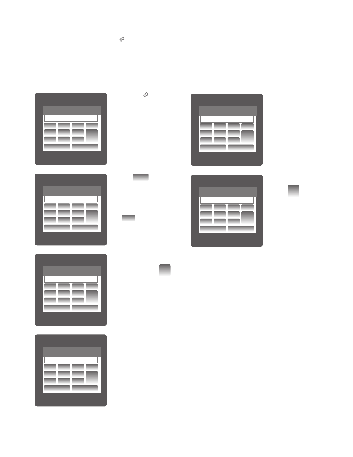
7.1. Password Protection
Password protection can be enabled to prevent unauthorised access to set-up screens, by default password is “0000”.
Password protection is enabled by selecting any four digit number.
After touching “
SETUP” icon
Password protection screen is
displayed. Screen consists of 0 to
9 digit input keypad for entering
the password very similar to any
calculator in touchscreen mobile.
“Enter Password” is displayed on
screen at start so that user can
enter password using displayed
keypad.
Password confirmed.
If Entered password is correct
then “Password Accepted”
is displayed on screen & user
will enter into setup menu.
Password Incorrect.
If Entered password is
wrong then “Password
Rejected” is displayed on screen & user
need to re-enter the
password
After wrong password
is entered, user needs
to touch “
ENTER
key” for trying another
password.
Touching “
1
key” will
display 1 in display area, similarly user can enter remaining
3 digits.
For deleting any digit while entering password, user can touch
DEL“
DEL
key”.
After entering the complete
password user needs to confirm
password by touching “
ENTER
key”.
SETUP
ENTER PASSWORD
1 2
3
4
5
6
7 8 9
0
BACK
DEL
ENTER
SETUP
1
1 2
3
4
5
6
7 8 9
0
BACK
DEL
ENTER
SETUP
1234
SETUP
PASSWORD ACCEPTED
1 2
3
4
5
6
7 8 9
0
BACK
DEL
ENTER
1 2
3
4
5
6
7 8 9
0
BACK
DEL
ENTER
SETUP
ENTER PASSWORD
1 2
3
4
5
6
7 8 9
0
BACK
DEL
ENTER
SETUP
1
1 2
3
4
5
6
7 8 9
0
BACK
DEL
ENTER
SETUP
1234
SETUP
PASSWORD ACCEPTED
SETUP
PASSWORD REJECTED.
PASSWORD
PRESS ENTER TO TRY AGAIN
1 2
3
4
5
6
7 8 9
0
BACK
DEL
ENTER
1 2
3
4
5
6
7 8 9
0
BACK
DEL
ENTER
1 2
3
4
5
6
7 8 9
0
BACK
DEL
ENTER
1 2
3
4
5
6
7 8 9
0
BACK
DEL
ENTER
PM 1000269 000 02 Device handbook SIRAX MM1400 14/60
7.2. Menu selection
After entering in the SUBMENU 6 - SETUP, user will be asked to enter password & after input of correct password list of following parameters
will be displayed on screen.
7.2.1 SYSTEM PARAMETERS 7.2.5 POWER QUALITY SETUP
7.2.2 COMMUNICATION PARAMETERS 7.2.6 CLOCK SETUP
7.2.3 RESET PARAMETERS 7.2.7 BRIGHTNESS & CONTRAST
7.2.4 TIME OF DAY SETUP
Touching on SYSTEM PARAMETER will open the system parameters list screen.Then these screens from particular parameter may be scrolled
through one at a time in incremental order by touching the “
key” and in decremental order by touching “ key” on given touch screen.
7.2.1 System Parameters Selection
After entering in the “SYSTEM PARAMETERS”, List of following parameters will be displayed.
7.2.1.1 SYSTEM TYPE 7.2.1.6 DEMAND INTEGRATION TIME
7.2.1.2 PT PRIMARY (L-L) 7.2.1.7 ENERGY UPDATE RATE
7.2.1.3 PT SECONDARY (L-L) 7.2.1.8 LOW CURRENT NOISE CUTOFF
7.2.1.4 CT PRIMARY 7.2.1.9 ENERGY RESOLUTION
7.2.1.5 CT SECONDARY 7.2.1.10 ENERGY DIGIT RESET COUNT
7.1.1. Change Password
Change Password Option is the second last option in list of “SETUP”
submenu, so can be accessed by a simple touch anywhere in
“Change Password” row.
In this screen user first needs to enter the current password.
After input of correct password, “PASSWORD ACCEPTED” is displayed
& now user can enter the new 4 digit password.
New Password confirmed.
After entering new password user needs to touch “
ENTER
key” to
confirm.
After confirming “PASSWORD CHANGED” is displayed on screen,
which ensures successful changing of the password.
PASSWORD
ENTER CURRENT PASSWORD
PASSWORD
ENTER NEW PASSWORD
PASSWORD
PASSWORD CHANGED
1 2
3
4
5
6
7 8 9
0
BACK
DEL
ENTER
1 2
3
4
5
6
7 8 9
0
BACK
DEL
ENTER
1 2
3
4
5
6
7 8 9
0
BACK
DEL
ENTER
PM 1000269 000 02 Device handbook SIRAX MM1400 15/60
7.2.1.1. System Type
7.2.1.2. Potential Transformer Primary Value
The nominal full scale voltage will be displayed as Line to Line Voltages for all system types.
7.2.1.3 Potential Transformer secondary Value
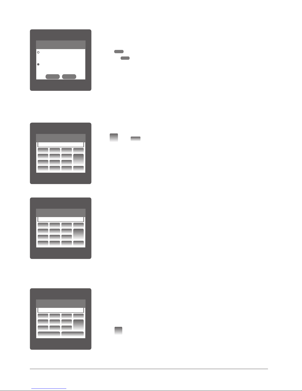
This screen is used to set the system type.
Two types: 3 phase 3 wire & 3 phase 4 wire system are displayed on screen. Touching radio
button in front of particular type will select that type.
Touch on “
OK
key” will confirm the system type.
Touching the “
BACK
key” will keep the old selected setting and will return to previous menu.
Note: If system type is changed, relay parameter selection & analog output selection will be set
to NONE.
This screen can be accessed only from system parameters list menu. Here again 0 to 9 digit
input keypad is provided to set value of PT Primary, & user can confirm this value with a simple
touch “
ENTER
key”. “K key” is used to multiply value by 1000.
In case presently displayed Potential Transformer Primary value together with the Current Transformer Primary value, previously set, would result in a maximum power of greater than 666.6
MVA per phase,”Invalid value” will be displayed. Then the valid range will be displayed.
The value must be set to the nominal full scale secondary voltage which will be obtained from
the the Transformer when the potential transformer(PT)primary is supplied with the voltage defined in 3.2.1.2 potential transformer primary voltage. The ratio of full scale primary to full scale
secondary is defined as the transformer ratio.
This screen can be accessed only from system parameters list menu. Here again 0 to 9 digit input keypad is provided to set value of PT Secondary, & user can confirm this value with a simple
touch on “
ENTER
key”.
Valid range of PT primary setting value is from
100 VL-L to 692.8 KVL-L.
If value outside the range is entered, It will display “INVALID VALUE” followed by correct range of
parameter.
Note: Setting PT primary value will reset all TOD data & all energies.
While setting PT primary value if auxiliary supply gets o, reset TOD data after auxiliary supply
gets on from reset parameter menu. Same is applicable for CT primary value also.
LINE-NEUTRAL VOLTAGE
VL2
VL2
VL2
VL2
0.000
LINE-NEUTRAL VOLTAGE
VL2
VL2
VL2
VL2
0.000
LINE-NEUTRAL VOLTAGE
VL2
VL2
VL2
VL2
0.000
SYSTEM TYPE
3-PHASE 4 WIRE
FOR 3 PHASE STAR CONNECTED LOAD
3-PHASE 3 WIRE
FOR 3 PHASE DELTA CONNECTED LOAD
MAINMAINMAINMAINMAINMAIN
OK BACK
LINE-NEUTRAL VOLTAGELINE-NEUTRAL VOLTAGELINE-NEUTRAL VOLTAGEPT PRIMARY
ENTER PT PRIMARY VALUE(L-L)
1 2
3
4
5
6
7
8 9
DEL
ENTER
0
K
BACK
LINE-NEUTRAL VOLTAGELINE-NEUTRAL VOLTAGELINE-NEUTRAL VOLTAGEPT PRIMARY
INVALID VALUE
1 2
3
4
5
6
7 8 9
DEL
ENTER
0
K
BACK
LINE-NEUTRAL VOLTAGELINE-NEUTRAL VOLTAGELINE-NEUTRAL VOLTAGEPT SECONDARY
ENTER PT SECONDARY VALUE(L-L)
1 2
3
4
5
6
7 8 9
DEL
ENTER
0
BACK
PM 1000269 000 02 Device handbook SIRAX MM1400 16/60
In case presently displayed Current Transformer Primary Value together with the Potential Transformer
Primary Value results in a maximum power of greater than 666.6 MVA, “invalid value” will be displayed. Example: If primary value of PT is set as 692.8kV L-L (max value) then primary value of Current
is restricted to 1157A.
The “Maximum Power” restriction of 666.6 MVA refers to 120% of nominal current and 120% of
nominal voltage, i.e, 462.96 MVA nominal power per phase.
This screen is used to set the secondary value for Current Transformer. Two options: 1 AMPERE & 5
AMPERE are displayed on screen. Touching radio button in front of particular option will select that
option. Touch on “
OK
key” will confirm the setting. Touching the “
BACK
key” will keep the old
selected setting and will return to previous menu.
Valid range of CT primary setting value is from 1 to 9999. If value outside the range is entered, It will
display “INVALID VALUE” followed by correct range of parameter.
Note: Setting PT primary value will reset all TOD data & all energies.
Valid range of PT secondary setting value is from 100.0 to 500.0 VL-L.
If value outside the range is entered, It will display “INVALID VALUE” followed by correct range of
parameter.
LINE-NEUTRAL VOLTAGELINE-NEUTRAL VOLTAGELINE-NEUTRAL VOLTAGEPT PRIMARY
ENTER PT PRIMARY VALUE(L-L)
1 2
3
4
5
6
7
8 9
DEL
ENTER
0
K
BACK
LINE-NEUTRAL VOLTAGELINE-NEUTRAL VOLTAGELINE-NEUTRAL VOLTAGEPT PRIMARY
INVALID VALUE
1 2
3
4
5
6
7 8 9
DEL
ENTER
0
K
BACK
LINE-NEUTRAL VOLTAGELINE-NEUTRAL VOLTAGELINE-NEUTRAL VOLTAGEPT SECONDARY
ENTER PT SECONDARY VALUE(L-L)
1 2
3
4
5
6
7 8 9
DEL
ENTER
0
BACK
LINE-NEUTRAL VOLTAGELINE-NEUTRAL VOLTAGELINE-NEUTRAL VOLTAGEPT SECONDARY
INVALID VALUE
1 2
3
4
5
6
7 8 9
DEL
ENTER
0
BACK
LINE-NEUTRAL VOLTAGELINE-NEUTRAL VOLTAGELINE-NEUTRAL VOLTAGECT PRIMARY
ENTER CT PRIMARY VALUE
1 2
3
4
5
6
7 8 9
DEL
ENTER
0
K
BACK
LINE-NEUTRAL VOLTAGELINE-NEUTRAL VOLTAGELINE-NEUTRAL VOLTAGECT PRIMARY
INVALID VALUE
1 2
3
4
5
6
7
8 9
DEL
ENTER
0
K
BACK
LINE-NEUTRAL VOLTAGELINE-NEUTRAL VOLTAGELINE-NEUTRAL VOLTAGECT PRIMARY
ENTER CT PRIMARY VALUE
1 2
3
4
5
6
7 8 9
DEL
ENTER
0
K
BACK
LINE-NEUTRAL VOLTAGELINE-NEUTRAL VOLTAGELINE-NEUTRAL VOLTAGECT PRIMARY
INVALID VALUE
1 2
3
4
5
6
7
8 9
DEL
ENTER
0
K
BACK
7.2.1.4 Current Transformer Primary Value
The nominal Full Scale Current that will be displayed as the Line currents. This screen enables the user to display the Line currents inclusive of
any transformer ratios, the values displayed representthe Current in Amps.
7.2.1.5 Current Transformer Secondary Value
PM 1000269 000 02 Device handbook SIRAX MM1400 17/60
This screen is used to set the period over which current and power readings are to be integrated.
Four options: 8, 15, 20, 30 Minutes are displayed on screen. Touching radio button in front of particular option will select that option.
Touch on “
OK
key” will confirm the setting.
Touching the “
BACK
key” will keep the old selected setting and will return to previous menu.
This screen allows user to enter energy update rate in min.
After entering particular value in min. the energy will be updated an modbus location from 30145 to
30153 of 3X register as per value that user has entered.
User can set value from 1 min to 60 min. II user enters value mora tnan 60 min. then "INVALID
VALUE" will be displayed and valid band will be shown.
Touching the "
BACK
key" will keep the ok! selected setting and will return to pravious menu.
For example user has entered 2 min as energy update rate. then after every 2 min, energy counts will
be updated on modbus.
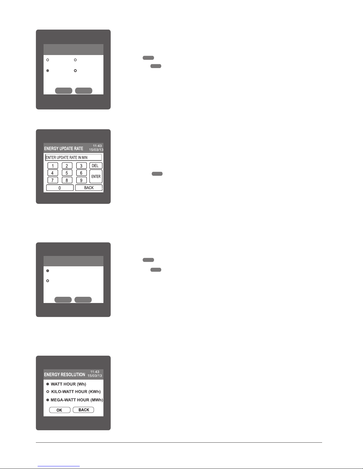
Two options, 0 MILLI-AMPERE & 30 MILLI-AMPERE are displayed on screen. Touching radio button
in front of particular option will select that option.
Touch on “
OK
key” will confirm the setting.
Touching the “
BACK
key” will keep the old selected setting and will return to previous menu.
Three options: WATT HOUR, KILO-WATT HOUR & MEGA-WATT HOUR
are displayed on screen. Touching radio button in front of particular option will select that option.
If (PT primary * CT primary * Root3) > 30000 KW then two options: KILO-WATT HOUR & MEGA-WATT
HOUR are displayed on screen.
Note: Default value is sei to 'WATI HOUR' i.e. Energy resolution will be in terms of Wh I
VArh I Vah respectively.
LINE-NEUTRAL VOLTAGE
VL2
VL2VL2
0.000
0.000
LINE-NEUTRAL VOLTAGE
VL2
VL2VL2
0.000
0.000
LINE-NEUTRAL VOLTAGE
VL2
VL2VL2
0.000
0.000
CT SECONDARY
5 AMPERE
1 AMPERE
LINE-NEUTRAL VOLTAGE
VL2
VL2VL2
0.000
0.000
LINE-NEUTRAL VOLTAGE
VL2
VL2VL2
0.000
0.000
LINE-NEUTRAL VOLTAGE
VL2
VL2VL2
0.000
0.000
DEMAND INTEGRATION TIME
8 MINUTES
15 MINUTES
20 MINUTES
30 MINUTES
MAINMAINMAINMAINMAINMAIN
OK BACK
LINE-NEUTRAL VOLTAGE
VL2
VL2VL2
LINE-NEUTRAL VOLTAGE
VL2
VL2VL2
LINE-NEUTRAL VOLTAGE
VL2
VL2VL2
CT SECONDARY
5 AMPERE
1 AMPERE
LINE-NEUTRAL VOLTAGE
VL2
VL2VL2
LINE-NEUTRAL VOLTAGE
VL2
VL2VL2
LINE-NEUTRAL VOLTAGE
VL2
VL2VL2
LOW CURRENT NOISE CUTOFF
0 MILLI-AMPERE
30 MILLI-AMPERE
MAINMAINMAINMAINMAINMAIN
OK BACK
7.2.1.6 Demand Integration Time
7.2.1.7 Energy update rate
7.2.1.8 Low Current noise cuto.
This screen allows the user to set Low noise current cuto in mA.
7.2.1.9 Energy Resolution
This screen enable user to set energy resolution in terms of Wh I kWh I MWh depending as per the user's requirement. This setting is applicable
for all types of energy.
 Loading...