

Camille Bauer SIRAX BT5700 User Manual
Operating Instructions
SIRAX BT5700
Programmable transducer for heavy current variables
Camille Bauer Metrawatt AG
Aargauerstrasse 7
CH-5610 Wohlen/Switzerland
Tel: +41 56 618 21 11
Fax: +41 56 618 21 21
info@cbmag.com
www.camillebauer.com
PM 1000284 000 01 Device handbook SIRAX BT5700 2/31
Legal information
Warning notices
In this document warning notices are used, which you have to observe to ensure personal safety and to prevent damage to property. Depending
on the degree of danger the following symbols are used:
Qualifi ed personnel
The product described in this document may be handled by personnel only, which is qualifi ed for the respective task. Qualifi ed personnel have
the training and experience to identify risks and potential hazards when working with the product. Qualifi ed personnel are also able to understand
and follow the given safety and warning notices.
Intended use
The product described in this document may be used only for the application specifi ed. The maximum electrical supply data and ambient conditions specifi ed in the technical data section must be adhered. For the perfect and safe operation of the device proper transport and storage as
well as professional assembly, installation, handling and maintenance are required.
Disclaimer of liability
The content of this document has been reviewed to ensure correctness. Nevertheless it may contain errors or inconsistencies and we cannot
guarantee completeness and correctness. This is especially true for di erent language versions of this document. This document is regularly
reviewed and updated. Necessary corrections will be included in subsequent version and are available via our webpage http://www.camillebauer.
com.
Feedback
If you detect errors in this document or if there is necessary information missing, please inform us via e-mail to:
customer-support@camillebauer.com
If the warning notice is not followed death or severe personal injury will result.
If the warning notice is not followed damage to property or severe personal injury may result.
If the warning notice is not followed the device may be damaged or may not fulfi ll the expected
functionality.

PM 1000284 000 01 Device handbook SIRAX BT5700 3/31
Table of content
1. Introduction ………………………………………………………………………………………………………………… 4
1.1 Purpose of this document ………………………………………………………………………………………………… 4
1.2 Scope of supply ………………………………………………………………………………………………………… 4
1.3 Further documents ………………………………………………………………………………………………………… 4
2. Safety notes ………………………………………………………………………………………………………………… 4
3. Device overview ……………………………………………………………………………………………………………… 5
3.1 Brief description …………………………………………………………………………………………………………… 5
3.2 Available measurement data ……………………………………………………………………………………………… 5
4. Mechanical mounting ………………………………………………………………………………………………………… 6
4.1 Mounting ………………………………………………………………………………………………………………… 6
4.2 Demounting of the device ………………………………………………………………………………………………… 6
5. Electrical connections ………………………………………………………………………………………………………… 7
5.1 General safety notes ……………………………………………………………………………………………………… 7
5.2 Cross sections and tightening torques ……………………………………………………………………………………… 7
5.3 Inputs ………………………………………………………………………………………………………………… 8
5.4 Power supply …………………………………………………………………………………………………………… 9
5.5 Connection diagram ……………………………………………………………………………………………………… 9
5.6 Modbus interface RS485 ………………………………………………………………………………………………… 9
6. Commissioning ……………………………………………………………………………………………………………… 9
6.1 Operating the device …………………………………………………………………………………………………… 10
6.2 Setup Parameter Screen ………………………………………………………………………………………………… 10
7. Programming ………………………………………………………………………………………………………………… 13
7.1. Password Protection ……………………………………………………………………………………………………… 13
7.1.1 Change Password New / Change Password ……………………………………………………………………………… 14
7.2 Menu selection ………………………………………………………………………………………………………… 15
7.2.1 System type selection ………………………………………………………………………………………………… 15
7.2.2 Potential Transformer primary Value …………………………………………………………………………………… 16
7.2.3 Current Transformer Primary Value ……………………………………………………………………………………… 16
7.2.4 Current Transformer Secondary Value …………………………………………………………………………………… 17
7.2.5 Energy Display on modbus …………………………………………………………………………………………… 17
7.2.6 RESET of parameters ………………………………………………………………………………………………… 18
7.2.7 Modbus Address ……………………………………………………………………………………………………… 18
7.2.8 Auto scrolling …………………………………………………………………………………………………………19
7.2.9 Start current Cuto …………………………………………………………………………………………………… 19
7.2.10 Baud Rate ……………………………………………………………………………………………………………20
7.2.11 Parity and Stop bits ………………………………………………………………………………………………… 20
7.2.12 Energy rate ………………………………………………………………………………………………………… 20
7.2.13 Energy digit reset count ………………………………………………………………………………………………21
8. Phasor Diagram ……………………………………………………………………………………………………………… 22
9. Programming via the RS485 (Modbus) interface ………………………………………………………………………………22
10. Service, maintenance and disposal ………………………………………………………………………………………… 23
10.1 Repair work and modifi cations …………………………………………………………………………………………… 23
10.2 Calibration and new adjustment …………………………………………………………………………………………… 23
10.3 Cleaning …………………………………………………………………………………………………………………23
10.4 Disposal ………………………………………………………………………………………………………………… 23
10.5 Return ………………………………………………………………………………………………………………… 23
11. Technical data ……………………………………………………………………………………………………………… 24
12. Dimensional drawings ……………………………………………………………………………………………………… 26
13. Interface Defi nition Modbus RTU …………………………………………………………………………………………… 27
13.1 Modbus functions ……………………………………………………………………………………………………… 27
13.2 Data types ……………………………………………………………………………………………………………… 27
PM 1000284 000 01 Device handbook SIRAX BT5700 4/31
1. Introduction
1.1 Purpose of this document
This document describes the universal measurement device SIRAX BT5700. It is intended to be used by:
•
Installation personnel and commissioning engineers
•
Service and maintenance personnel
•
Planners
Scope
This handbook is valid for all hardware versions of the BT5700. Some of the functions described in this document are available only, if the necessary optional components are included in the device.
Required knowledge
A general knowledge in the fi eld of electrical engineering is required. For assembly and installation of the device knowledge of applicable national
safety regulations and installation standard is required.
1.2 Scope of supply
•
Measurement device SIRAX BT5700
•
Safety instructions (multiple languages)
1.3 Further documents
The following documents are provided electronically via www.camillebauer.com:
•
Safety instructions SIRAX BT5700
•
Operating Instructions SIRAX BT5700
•
Data sheet SIRAX BT5700
2. Safety notes
Device may only be disposed in a professional manner!
The installation and commissioning should only be carried out by trained personnel.
Check the following points before commissioning:
- that the maximum values for all the connections are not exceeded, see „Technical data“ section,
- that the connection wires are not damaged, and that they are not live during wiring,
- that the power fl ow direction and the phase rotation are correct.
The instrument must be taken out of service if safe operation is no longer possible (e.g. visible damage). In this
case, all the connections must be switched o . The instrument must be returned to the factory or to an authorized
service dealer.
It is forbidden to open the housing and to make modifi cations to the instrument. The instrument is not equipped
with an integrated circuit breaker. During installation check that a labeled switch is installed and that it can easily
be reached by the operators.
Unauthorized repair or alteration of the unit invalidates the warranty.

PM 1000284 000 01 Device handbook SIRAX BT5700 5/31
3. Device overview
3.1 Brief description
The universal measuring device SIRAX BT5700 is suited for fi xed mounting and the measurement of Voltage, current, frequency, power, energy
(active / reactive / apparent), power factor, phase angle, etc in low voltage switchgear. The units are designed for unbalanced load network forms
of 3-phase mains with 3- or 4-wire.
3.2 Available measurement data
Measured Parameters Units 3P 3W 3P 4W
System Voltage U V • •
Voltage U1N / U2N / U3N V – •
Voltage U12 / U23 / U31 V • •
System Current I A • •
Current I1 / I2 / I3 A • •
Neutral Current IN (calc.) A – •
Frequency F Hz • •
Active Power P / P1 / P2 / P3 kW – •
Reactive Power øQ / Q1 / Q2 / Q3 kVAr – •
Apparent Power øS / S1 / S2 / S3 kVA – •
Power Factor PF1 / PF2 / PF3 – – •
Phase Angle Phi1 / Phi2 / Phi3 degree – •
Active Import Energy (8 Digit resolution) kWh • •
Active Export Energy (8 Digit resolution) kWh • •
Capacitive Reactive Energy (8 Digit resolution) kVArh • •
Inductive Reactive Energy (8 Digit resolution) kVArh • •
Apparent Energy (8 Digit resolution) kVAh • •
Max Current Demand A • •
Apparent Power Demand kVA • •
Min / Max System Voltage V • •
Min / Max System Current A • •
PM 1000284 000 01 Device handbook SIRAX BT5700 6/31
4. Mechanical mounting
The SIRAX BT5700 is designed for panel mounting.
4.1 Mounting
Dimensional drawing BT5700: See section 11
Any mounting position is possible. Device may be clipped onto a top-hat rail according EN50022 in a cabinet.
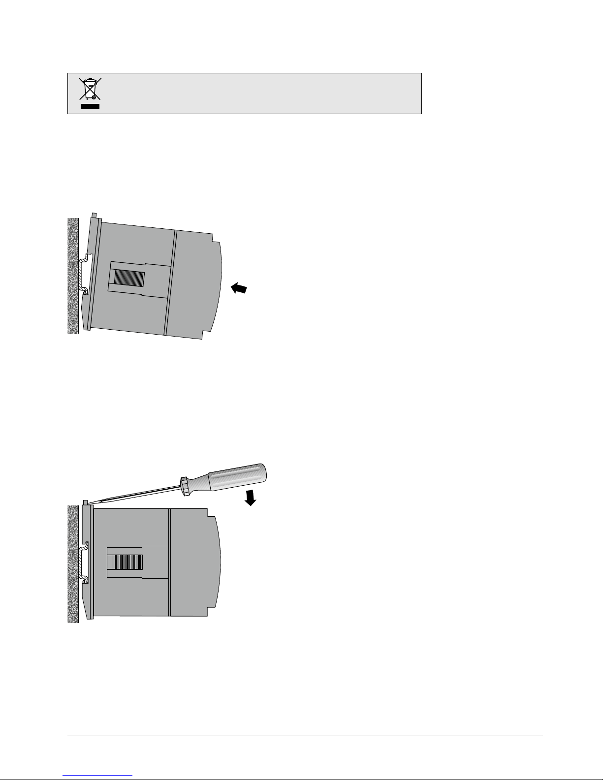
4.2 Demounting of the device
Disassembly of the device requires that all connected wires be without current. First, remove all push terminals and the wires of the current and
voltage inputs. Ensure that possible current transformers are short-circuited before the current connections on the device are opened.
Please ensure that the operating temperature limits are not exceeded when determining
the place of mounting (place of measurement): –10 … +55° C
PM 1000284 000 01 Device handbook SIRAX BT5700 7/31
5. Electrical connections
Ensure under all circumstances that the leads are free of potential when
connecting them!
Please observe that the data on the type plate must be adhered to!
The national provisions have to be observed in the installation and material selection of
electric lines!
5.1 General safety notes
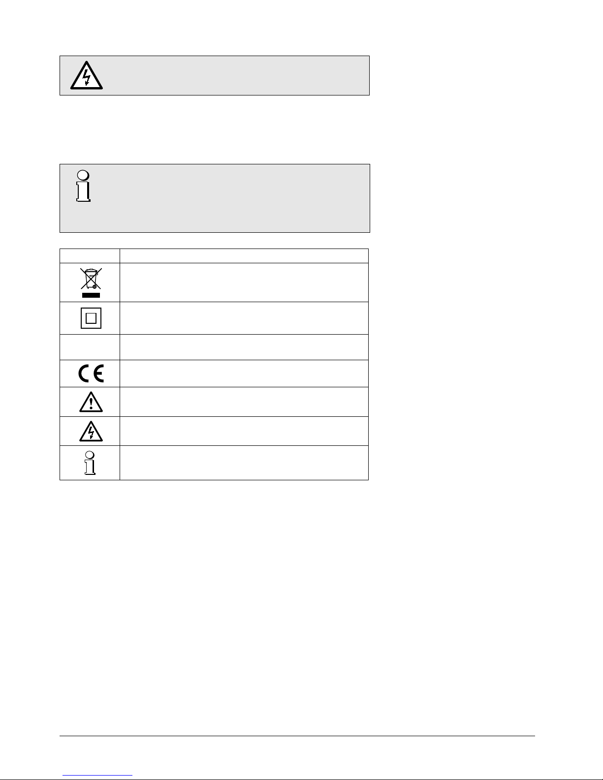
Symbol Meaning
Device may only be disposed of in a professional manner!
Double insulation, device of protection class 2
CAT III Measurement category CAT III for current / voltage inputs, power supply
and relay outputs
CE conformity mark. The device fulfi lls the requirements of the applicable
EC directives. See declaration of conformity.
Caution! General hazard point. Read the operating instructions.
Attention: Danger to life!
Please note
5.2 Cross sections and tightening torques
Terminals 1 … 14
Single wire: ≤ 4,0mm2 or multiwire with end splices: 2 x 2,5mm
2
Torque: 0.5 … 0.6Nm rsp. 4.42 … 5.31 lbf in
Terminal A, B, G
Single wire: ≤ 1,5mm2 or multiwire with end splices: 2 x 0,5mm
2
Torque: max. 0.5 Nm rsp. 4.42 lbf in
PM 1000284 000 01 Device handbook SIRAX BT5700 8/31
All voltage measurement inputs must originate at circuit breakers or fuses rated by 1 Amps. This
does not apply to the neutral connector. You have to provide a method for manually removing
power from the device, such as a clearly labeled circuit breaker or a fused disconnect switch.
When using voltage transformers you have to ensure that their secondary connections never will be
short-circuited.
No fuse may be connected upstream of the current measurement inputs!
When using current transformers their secondary connectors must be short-circuited during
installation and before removing the device. Never open the secondary circuit under load.
The connection of the inputs depends on the confi gured system (connection type).
5.4 Power supply
A marked and easily accessible current limiting switch has to be arranged in the vicinity of the
device for turning o the power supply. Fusing should be 10 Amps or less and must be rated for
the available voltage and fault current.
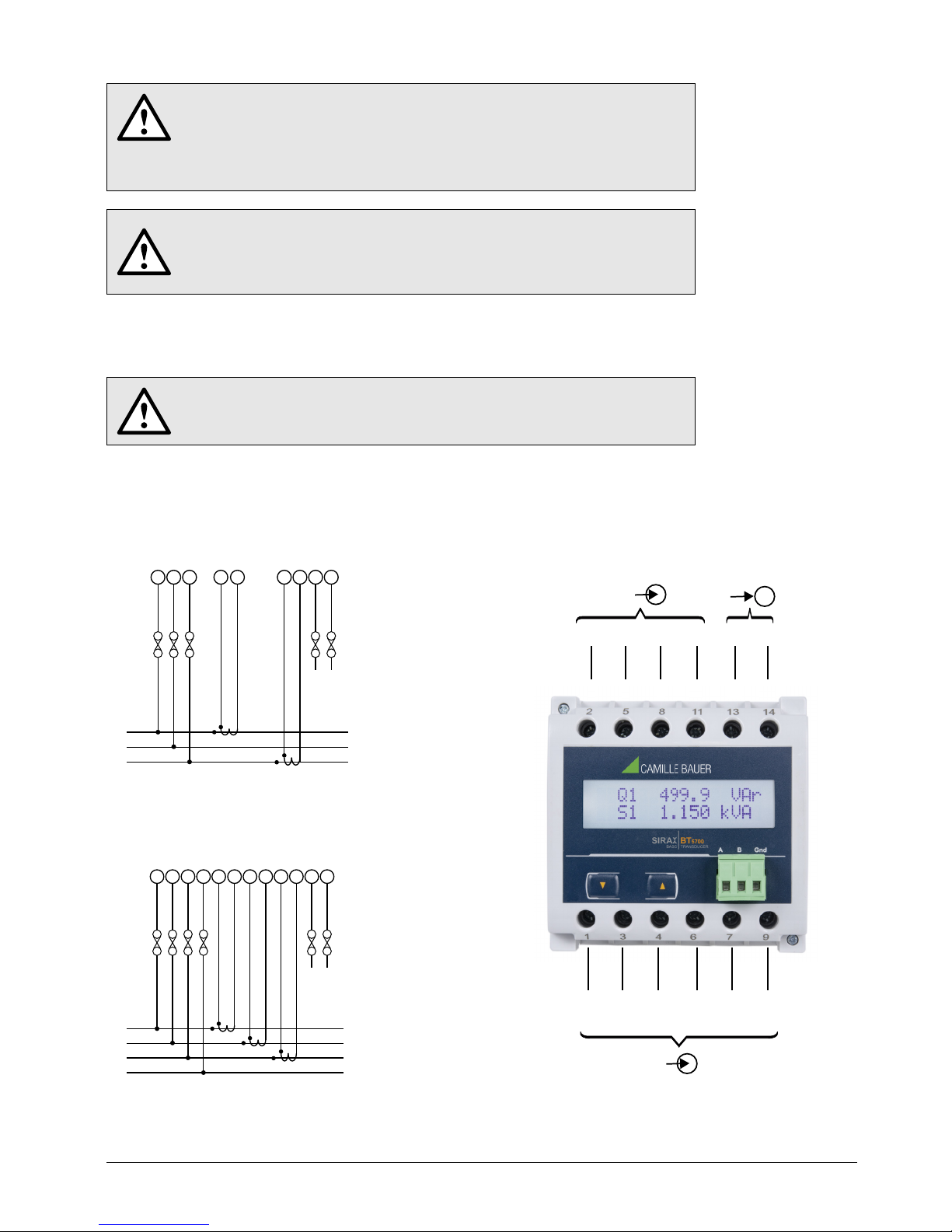
5.5 Connection diagram
Three wire, three phase system, unbalanced load, Aron connection (3P 3W)
2
L1
LN
AUX
SUPPLY
P1P1S1
S1
L2
L3
1 3 7 9 13 1458
/
2
$
'
Four wire, three phase system, unbalanced load (3P 4W)
2
L1
LN
AUX
SUPPLY
P1P1S1
S1
L2
L3
N
1 3 7 9 13 1458
/
2
$
'
11
P1 S1
4 6
5.3 Inputs
Direct connection
Direct connection
2
U1 U2 U3 N
Input U
AUX
581113 14
~~
-+
Input-I
5
8
I1 I2I1´ I2´ I3 I3´
134 67 9
RS485
PM 1000284 000 01 Device handbook SIRAX BT5700 9/31
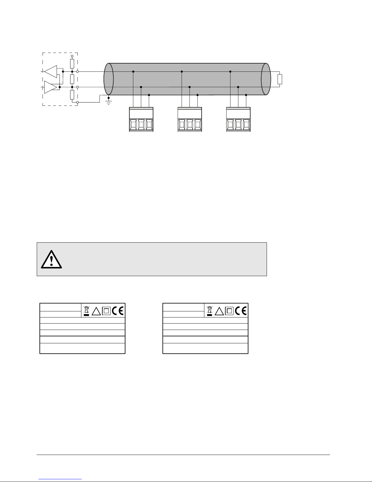
5.6 Modbus interface RS485
Via the optional Modbus interface measurement data may be provided for a superior system.
MASTER
+3.3 / +5V
Rx/Tx+,A
RS485 Bus
Rs
Rt
Rs
Rx/Tx-,B
GND
1)
Rt
ABG ABG ABG
The signal wires (A, B) have to be twisted. GND (G) can be connected via a wire or via the cable screen. In disturbed environments shielded
cables must be used. Supply resistors (Rs) have to be present in bus master (PC) interface. Stubs should be avoided when connecting the
devices. A pure daisy chain network is ideal.
You may connect up to 32 Modbus devices to the bus. A proper operation requires that all devices connected to the bus have equal
communication settings (baud rate, transmission format) and unique Modbus addresses.
The bus system is operated half duplex and may be extended to a maximum length of 1200 m without repeater.
6. Commissioning
Before commissioning you have to check if the connection data of the device match the data of
the plant.
If so, you can start to put the device into operation by switching on the power supply and the
measurement inputs.
1) One ground connection only. This is
possibly made within the master
(PC).
Rt: Termination resistors: 120 Ω each for
long cables (> approx. 10 m)
Rs: Bus supply resistors,
390 Ω each
ORDER CODE: 175275
SR No.: 15/11/0001
SIRAX BT5700
AUXILIARY: 12...48V DC, 4VA
CLASS: 0.5
INPUT: 3PH. 440 V L - L, 5A/1A, 45...65Hz
CAT III 300V Max. V40.05
OPTION: RS485
!
Label version RS485
(Article-Nr. 175 275)
ORDER CODE: 175134
SR No.: 15/11/0001
SIRAX BT5700
AUXILIARY: 100...250V AC/DC, 4VA
CLASS: 0.5
INPUT: 3PH. 440 V L - L, 5A/1A, 45...65Hz
CAT III 300V Max. V40.05
OPTION: RS485
!
Label version RS485
(Article-Nr. 175 134)

PM 1000284 000 01 Device handbook SIRAX BT5700 10/31
6.1 Operating the device
6.2 Setup Parameter Screen
SIRAX BT5700 can be confi gured and programmed at site for the following: PT Primary,
CT Primary, CT Secondary (5A or 1A) & three wire, three phase system or four wire,
three phase system. The front panel has two push buttons through which the User may
scroll through the available measurement readings, reset the energy (Import/Export) Min/
Max (System Voltage & System Current) & confi gure the product.
Operation is performed by means of 2 keys:
2 keys “
UP” und “ DOWN” for navigation and for the selection of values.
UP KEY
DOWN
KEY
Change password
(Section 7.1.1)
Enter password
(Section 7.1)
Energy OP
(Section 7.2.5)
CT SEC
(Section 7.2.4)
Set Energy
output
1: Wh
2: kWh
3: MWh
Applicable
to all Energy
NONE: No parameter
ALL: All parameters
ENERGY: Energy
MAX: Max values
MIN: Min values
Select any one option
using „DOWN“ key.
CT PRI
(Section 7.2.3)
PT PRI
(Section 7.2.2)
Set PT
Primary
Set CT
Primary
Set CT
Secondary
5A/1A
Sys Type
(Section 7.2.1)
Select
System
Type
3 - 3P 3W
4 - 3P 4W
Enr rst
cnt
(Section 7.2.13)
Energy
rate
(Section 7.2.12)
Parity/
Stop bits
(Section 7.2.11)
Baud Rate
(Baud Rate)
(Section 7.2.10)
30 mA
Cuto
(Section 7.2.9)
Auto
(Auto Scrolling)
(Section 7.2.8)
MODBUS ADD
Modbus Address
(Section 7.2.7)
Set Modbus
Address
Screen Auto
scrolling
Enable / Disable
Noise
current
cuto Enable
/ Disable
Set baud rate
2400/4800/
9600/19200
Set Combination
of Parity & no.
Of Stop bit
Set energy
Update Rate
(1 to 60min)
Exit Set UP &
Return to
Normal Operation
Set energy
digit reset
count (7 to 14)
RESET
Reset Parameter
(Section 7.2.6)
CODE (password)
DOWN UP
 Loading...