

Camille Bauer SIRAX B 811 Quick Start Manual

Plug-in Module SIRAX B 811
Power Pack with Additional Functions
for intelligent and conventional
2-wire transmitters
Application
The power supply unit SIRAX B 811 (Fig. 1) provides the DC power
supply for 2-wire transmitters and transfers the measured variable
unchanged to the electrically insulated output.
Conversion to a different signal range such as 0…5 mA or
1…5 V (signal converter) is also possible.
Some versions of the SIRAX B 811 are designed for FSK
munication. They are used in conjunction with “intelligent” 2-wire
transmitters which are capable of dialogue and operation according
to the FSK principle and the HART or user-specific protocol.
The series also includes “intrinsically safe” versions [EEx ia] IIC with
an intrinsically safe measurement/supply circuit. These operate
in conjunction with intrinsically safe 2-wire transmitters located in
explosion hazard areas.
Provision is made for monitoring the measurement/supply circuit
to detect short and open-circuits. Either of these faults is signalled
by the fault signalling relay AF and the red LED. The output signals A1 and A12 can be set on the DIP switches to have a linear
increasing or decreasing response.
The power pack fulfils all the important requirements and regulations concerning electromagnetic compatibility EMC and Safe
Isolation (IEC 1010 resp. EN 61 010). It was developed and is
manufactured and tested in strict accordance with the quality
assurance standard ISO 9001.
Production QA is also certified according to guideline 94/9/EG.
1
com-
0102
II (1) G
Fig. 1. Plug-in module SIRAX B 811 for plugging onto backplane
BP 902.
●
Output can be switched between 0…20 mA and 4…20 mA / Universal
matching to suit downstream device
Green LED signals a power supply failure
●
Features / Benefits
Technical data
● Power pack plugs onto backplane (mechanically latched by fasteners),
all electrical connections made to the backplane and not to the
SIRAX B 811 / Thus no wiring when replacing devices
Designed for FSK communication, hand-held terminal connected to
●
separate terminals. This facilitates operation in conjunction with an
“intelligent” 2-wire transmitter designed for FSK and with a HART or
user-specific protocol
Electrically insulated between input circuit, output and power supply /
●
Fulfils IEC 1010 resp. EN 61 010 Part 2
AC/DC power supply / Universal
●
Available in type of protection “Intrinsically safe” [EEx ia] IIC
●
(see “Table 5: Data on explosion protection”)
Measurement/supply circuit monitored for open and short-circuits /
●
Faults signalled by red LED, signalling relay and/or device failure
signal
Camille Bauer Data sheet B811-6 Le – 09.07 1
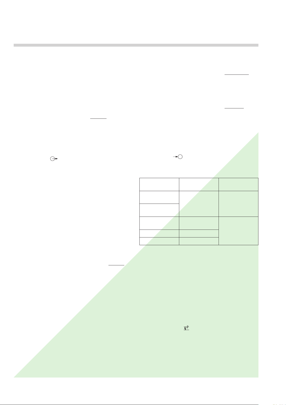
Input circuit (MSK)
Signal range IE: 4…20 mA DC
Supply voltage US (at IE = 20 mA):
24 V ± 7%
24 V ± 7%
> 16.9 V
> 16.4 V
1
FSK = Frequency Shift Keying
with standard (non-Ex) version,
not designed for communications protocol
with standard (non-Ex) version,
designed for FSK communication
with Ex versions,
not designed for communications protocol
with Ex versions,
designed for FSK communication
2 Data sheet B811-6 Le – 09.07 Camille Bauer
Plug-in Module SIRAX B 811
Power Pack with Additional Functions
Current limiter: Electronic
At IE > 30 mA, US is switched to 0 V
for approx. 1 s.
U
Max. line resistance
: The maximum line resistance R
is then automatically readjusted
S
to its set-point
permissible between the 2-wire
line
transmitter and the supply unit
depends on the voltage difference
– UM:
U
S
– U
U
S
R
max. =
Ltg
U
2-wire transmitter
U
= Supply voltage for
S
= Min. operating voltage of the
M
2-wire transmitter
M
20 mA
Measuring output
Output signals A1 and A12
(see Section “Electrical connections”)
The output signals A1 and A12 can be load-independent DC
voltages U
A1 and A12 are not electrically insulated; the same value is available at both outputs.
DC voltage signals U
Standard ranges for UA: 0…5, 1…5, 0…10 or 2…10 V
Non-standard ranges: 0…> 5 to 0…15 V
resp. live-zero
> (1…5) to 3…15 V
Short-circuit current: ≤ 40 mA
Load capacity UA1/U
Load impedance UA1/U
Residual ripple
or currents IA.
A
A
: 20 mA
A12
A12
: R
ext A1
// R
ext A12
[kΩ] ≥
: < 1% p.p., DC … 10 kHz
[V]
U
A
20 mA
of the jumpers J 204 and J 205. The full burden voltage of 15 V
is then available at output A1 instead of 10 V.
External resistance IA1: R
I
Burden voltage I
External resistance I
Residual ripple
: < 0.3 V (field indicator)
A12
: R
A12
: < 1% p.p., DC … 10 kHz
max. [kΩ] =
ext
= Output circuit full-scale value
AN
max. [kΩ] =
ext
15 V (10 V)
[mA]
I
AN
0.3 V
[mA]
I
AN
Response time (IEC 770): Approx. 200 ms
Output characteristic
: Linear
Power supply H
AC/DC power pack (DC and 45…400 Hz)
Table 1: Nominal voltages and tolerances
Nominal voltage
U
N
Tolerance
24... 60 V
DC / AC
85...230 V
1
DC – 15...+ 33%
AC ± 15%
DC / AC
24... 60 V
DC / AC
DC – 15...+ 33%
AC ± 15%
85...230 V AC ± 10%
85...110 V DC – 15...+ 10%
1
For power supplies > 125 V, the auxiliary circuit should include an external
fuse with a rating ≤ 20 A DC.
Power input: Approx. 2.5 W resp. ≤ 4.5 VA
Instrument
version
Standard
(non-Ex)
Type of
protection
“Intrinsically safe”
[EEx ia] IIC
DC current signals I
A
Standard ranges for IA: 0…20 mA or 4…20 mA
selected by jumpers
Communication
Bi-directional communication of digital signals with an “intelligent”
2-wire transmitter designed for FSK and a HART or companyspecific protocol.
Non-standard ranges
resp. live-zero
: 0…1 to 0…< 20 mA
Frequency range
: 500 Hz … 35 kHz
0.2…1 to < (4…20) mA
Open-circuit voltage: Approx. – 7…+ 22 V
Burden voltage IA1: 15 V without communication
10 V (15 V) with communication*
*When a hand-held terminal is connected to the field output A12,
the voltage across the burden at output A1 reduces to 10 V. Digital communication requires a minimum burden at output A1 of
250 Ω. A 250 Ω resistor is therefore connected across the output
circuit. If the load of the burden across output A1 already exceeds
250 Ω, the resistor can be disconnected by changing the position
Input circuit monitor
Pick-up level: – Open-circuit
Input current < 3.6 mA,
adjustable in the works between
1 to 4 mA
– Short-circuit
Input current > 21 mA
adjustable in the works between
20 to 23 mA
Camille Bauer Data sheet B811-6 Le – 09.07 3
Plug-in Module SIRAX B 811
Power Pack with Additional Functions
Signalling modes
Output signals
A12: – Output signal linear response
A1 and
For an open-circuit output
0 mA (with 4…20 mA)
– 5 mA (with 0…20 mA)
For a short-circuit
output approx. 26 mA
– Increasing output signal
Output approx. 115% of full-scale
value, e.g. 23 mA for output
0/4…20 mA
or
11.5 V for output 0/2…10 V
– Decreasing output signal
(only possible for live zero)
Output approx. 10% of full-scale
value, e.g.
output 4…20 mA
or 1 V for output 2…10 V
Frontplate signals
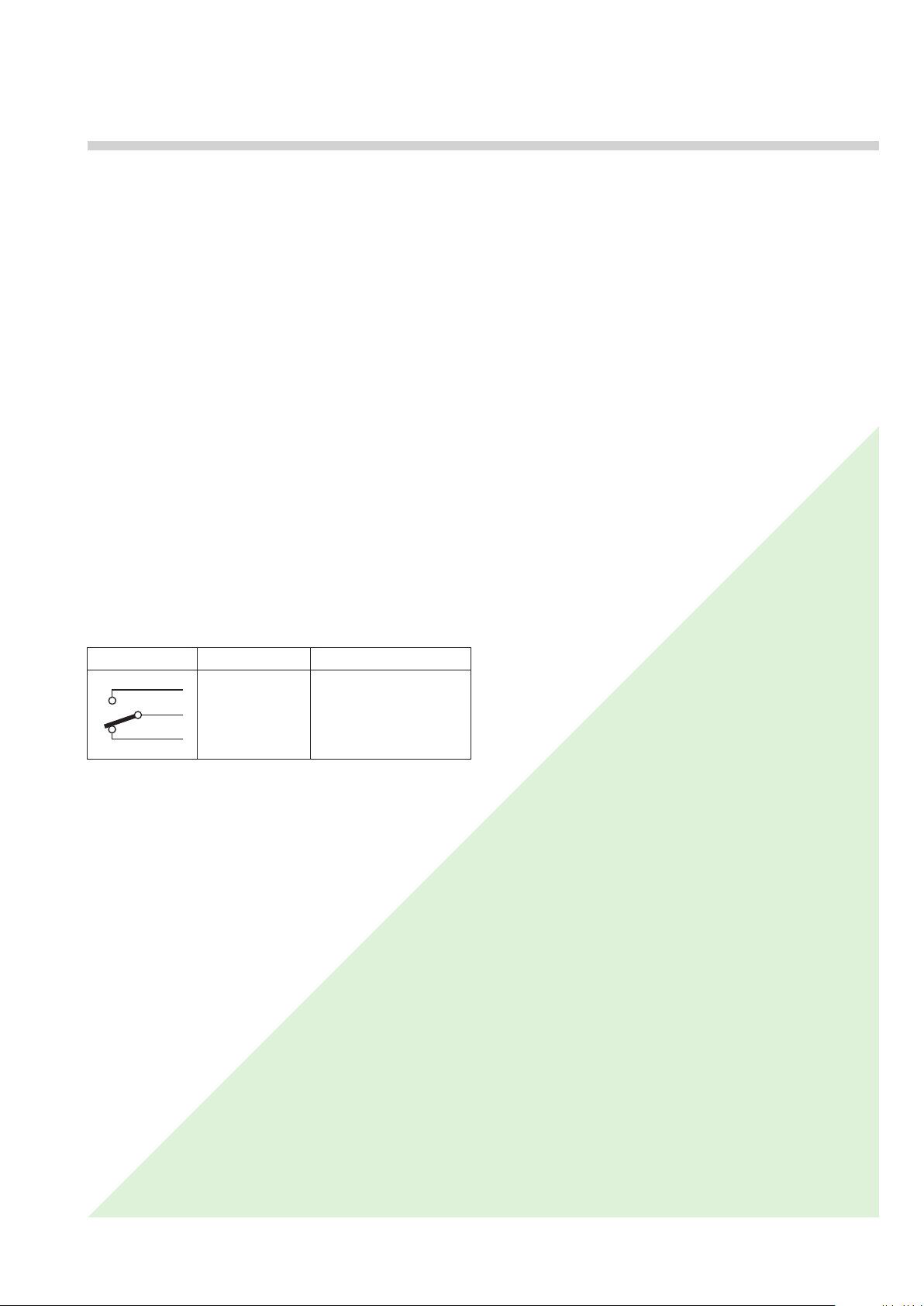
Output contact
Table 2: Type of output contact
Symbol Material Contact rating
Relay approved by UL, CSA, TÜV, SEV
Direction of action
– Relay “energized” or “de-energized”
in the case of a failure
: Failure signalled by red LED
AF: 1 relay, 1 potentially-free changeover
contact (see Table 2)
AC: ≤ 2 A / 250 V
Gold flashed
silver alloy
: Adjustable by switch
(500 VA)
DC: ≤ 1 A / 0.1…250 V
(30 W)
Accuracy data (acc. to DIN/IEC 770)
Basic accuracy: Limit error ≤ ± 0.2%
Including linearity and reproducibility
errors
Reference conditions:
Ambient temperature
Power supply 24 V DC ± 10% and
230 V AC ± 10%
Output burden Current: 0.5 · R
Voltage: 2 · R
Influencing factors:
Temperature < ± 0.1% per 10 K
Burden influence < ± 0.1% with current output
< 0.2% with voltage output,
if R
23 °C, ± 2 K
> 2 · R
ext
ext
ext
min.
max.
ext
min.
Long-time drift
Switch-on drift < ± 0.2%
Common and transverse
mode influence < ± 0.2%
Output + or –
connected to ground: < ± 0.2%
< ± 0.3% / 12 months
Standards
Electromagnetic
compatibility: The standards DIN EN 50 081-2 and
DIN EN 50 082-2 are observed
Intrinsically safe
Electrical standards: Acc. to IEC 1010 resp. EN 61 010
Protection (acc. to IEC 529
resp. EN 60 529): Housing IP 40
Terminals IP 00
Operating voltage: Measuring input < 30 V
Measuring outputs < 25 V
Output contact,
Power supply < 250 V
Rated insulation voltage
Contamination level
Overvoltage category
acc. to IEC 664: III for power supply
II for measuring input, measuring
Electrical insulation: Power supply versus all other cir-: Power supply versus all other cir-Power supply versus all other cir-
measuring input versus measuring
Test voltage
Measuring input versus measuring
Measuring output versus output
: Acc. to DIN EN 50 020: 1996-04
: 253 V AC for all circuits
: 2
output and output contact
cuits,
output and output contact
: Power supply versus measuring
input, measuring output and output
contact 3.7 kV, 50 Hz, 1 min.
output 2.3 kV, 50 Hz, 1 min.
contact 2.3 kV, 50 Hz, 1 min.
Environmental conditions
Commissioning
temperature: – 10 to + 40 °C
Operating temperature: – 25 to + 40 °C,
Ex –20 to + 40 °C
Storage temperature
Annual mean
relative humidity: ≤ 75%
Altitude: 2000 m max.
Indoor use statement!
: – 40 to + 70 °C
 Loading...