

Camille Bauer Sineax V604s, Sineax VB604s, Sineax VQ604s Safety Instructions

Sicherheitshinweise, die unbedingt beachtet werden müssen, sind
in dieser Anleitung mit folgen denden Symbolen markiert:
Geräte dürfen nur fachgerecht entsorgt werden!
Sicherheitshinweise
Camille Bauer Metrawatt AG
Aargauerstrasse 7
CH-5610 Wohlen/Switzerland
Telefon +41 56 618 21 11
Telefax +41 56 618 21 21
info@cbmag.com
www.camillebauer.com
SINEAX V604s,
VB604s, VQ604s
Multifunktionaler
Messumformer
168 501-05 06.17
PM1000752 000 01
Erst lesen, dann …
Der einwandfreie und gefahrlose Betrieb setzt
voraus, dass dieser Sicherheitshinweis, sowie die
Betriebsanleitung gelesen und verstanden wurde!
Der Umgang mit diesem Gerät sollte nur durch
entsprechend geschultes Personal erfolgen, das
das Gerät kennt und berechtigt ist, Arbeiten in
technischen An lagen auszuführen.
Das Gerät muss ausser Betrieb gesetzt werden,
wenn ein gefahrloser Betrieb (z.B. bei sichtbaren
Beschädigungen) nicht mehr möglich ist. Dabei
sind alle Anschlüsse abzuschalten. Das Gerät ist
an unser Werk bzw. an eine durch uns autorisierte
Servicestelle zu schicken.
Bei einem Eingriff in das Gerät erlischt der Garantieanspruch!
www.camillebauer.com/vx604s-de
Lieferumfang
1 SINEAX V604s, VB604s oder VQ604s
1 Sicherheitshinweise 168 501
Kurzbeschreibung
Der SINEAX V604s, VB604s bzw. VQ604s ist ein programmierbarer
multifunktionaler Messumformer für Hutschienen-Montage. Eingang,
Ausgang, Bus und Hilfsenergie sind galvanisch voneinander getrennt.
Programmierung und Kommunikation erfolgt über eine ModbusSchnittstelle.
Technische Daten
Messeingang
2 Messeingänge galvanisch verbunden. Bei 2 Sensoren Beschaltungshinweise in der Betriebsanleitung beachten!
Messart Messbereich Minimale Spanne
DC-Spannung [mV] –1000 … 1000 mV 2 mV
DC-Spannung [V] * –600 … 600 V
DC-Strom [mA] –50 … 50 mA 0,2 mA
Widerstand [Ω] 0 … 5000 Ω 8 Ω
RTD Pt100 –200 ... 850 °C 20 K
RTD Ni100 –60 ... 250 °C 15 K
TC Typ B 0 ... 1820 °C 635 K
TC Typ E –270 ... 1000 °C 34 K
TC Typ J –210 ... 1200 °C 39 K
TC Typ K –270 ... 1372 °C 50 K
TC Typ L –200 ... 900 °C 38 K
TC Typ N –270 ... 1300 °C 74 K
TC Typ R –50 ... 1768 °C 259 K
TC Typ S –50 ... 1768 °C 265 K
TC Typ T –270 ... 400 °C 50 K
TC Typ U –200 ... 600 °C 49 K
TC Typ W5Re-W26Re 0 ... 2315 °C 135 K
TC Typ W3Re-W25Re 0 ... 2315 °C 161 K
* nicht beim VB604s und VQ604s
1)
Bei älteren Geräteversionen ist der Messbereich nur -300...300V. Bitte vor
Gebrauch Geräteversion prüfen, anhand des Typenschildes oder mit der CBManager Software.
1 Sicherheitshinweise V604s, VB604s und VQ604s Camille Bauer Metrawatt AG
1)
>1 V
Ausgänge
2 analoge Ausgänge, galvanisch verbunden, gemeinsame Masse.
Spannungs- oder Stromausgang sind beim V604s/VB604s mit Software konfigurierbar, beim VQ604s nur bei entsprechender Geräteausführung.
Gleichstrom
Gleichspannung
Relais-Kontaktausgang
Variante Relais:
Kontakt 1 Pol, Schliesskontakt (NO)
Schaltleistung AC: 2A/250V, DC: 2A/30V
Variante digitaler Ausgang*:
Kontakt Transistor, Schliesskontakt (NO)
Schaltleistung max. 27VDC/27mA
Bus-/Programmieranschluss
Schnittstelle, Protokoll RS485, Modbus RTU
Hilfsenergie
Nennspannung U
24 … 230 V DC * ± 15%
100 … 230 V AC, 50/60 Hz ± 15%
Grüne LED = «Power ON» Anzeige
*
Bereich ±20 mA, Bürdenspannung 12 V
Leerlaufspannung < 20 V
Begrenzung max. ±22 mA
Bereich ±10 V,
Belastung max.: V604s/VB604s: 20 mA, VQ604s: 0,02 mA
Strombegrenzung ca. 30 mA
Begrenzung max. ±11 V
N
Bei einer Hilfsenergiespannung >125 V DC muss im Hilfsener-
giekreis eine externe Sicherung vorgesehen werden.
Toleranz-Angabe
Elektrische Anschlüsse
Zum Anschliessen der elektrischen Leitungen dienen steckbare Schrauboder Zugfederklemmen, welche sich für Drahtquerschnitte bis max.
2,5 mm2 eignen.
Unbedingt sicher stellen, dass alle Leitungen beim
Anschliessen spannungsfrei sind!
Möglicherweise drohende Gefahr durch hohe
Spannungen.
Es ist zu beachten, …
… dass die Daten auf dem Typen schild eingehalten werden!
Zum Abschalten der Hilfsenergie ist in der Nähe des Gerätes ein
gekennzeichneter, leicht erreichbarer Schalter vorzusehen.
Beim Einschalten der Hilfsenergie muss die Hilfsenergiequelle
kurzzeitig genügend Strom (ca. 0,3 A) liefern können.
Im übrigen sind die landesübliche Vorschriften (z.B. für Deutschland VDE 0100 «Bedingungen über das Errichten von Starkstromanlagen mit Nennspannungen unter 1000 Volt») bei
der Installation und Auswahl des Materials der elektrischen
Leitungen zu befolgen!
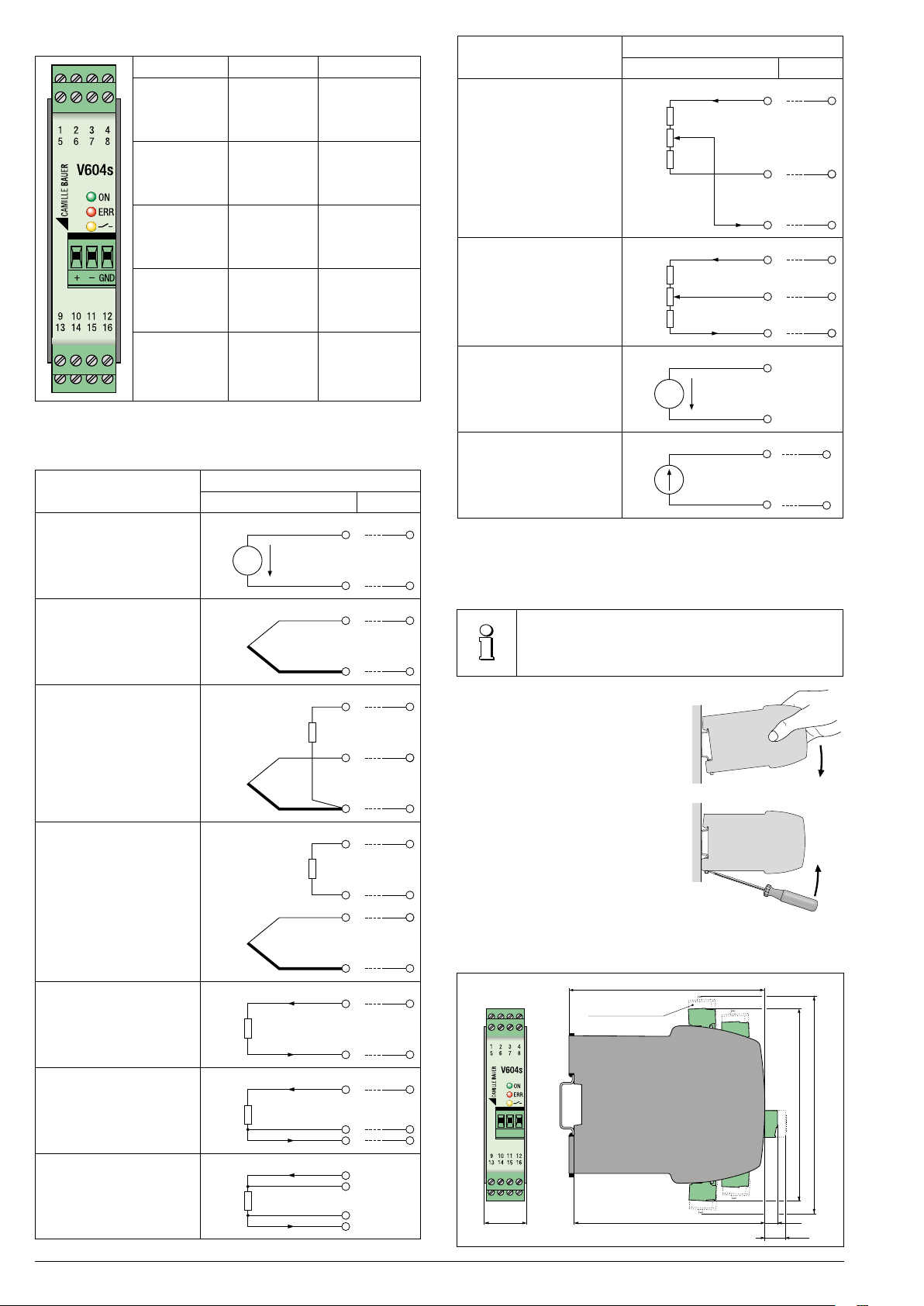
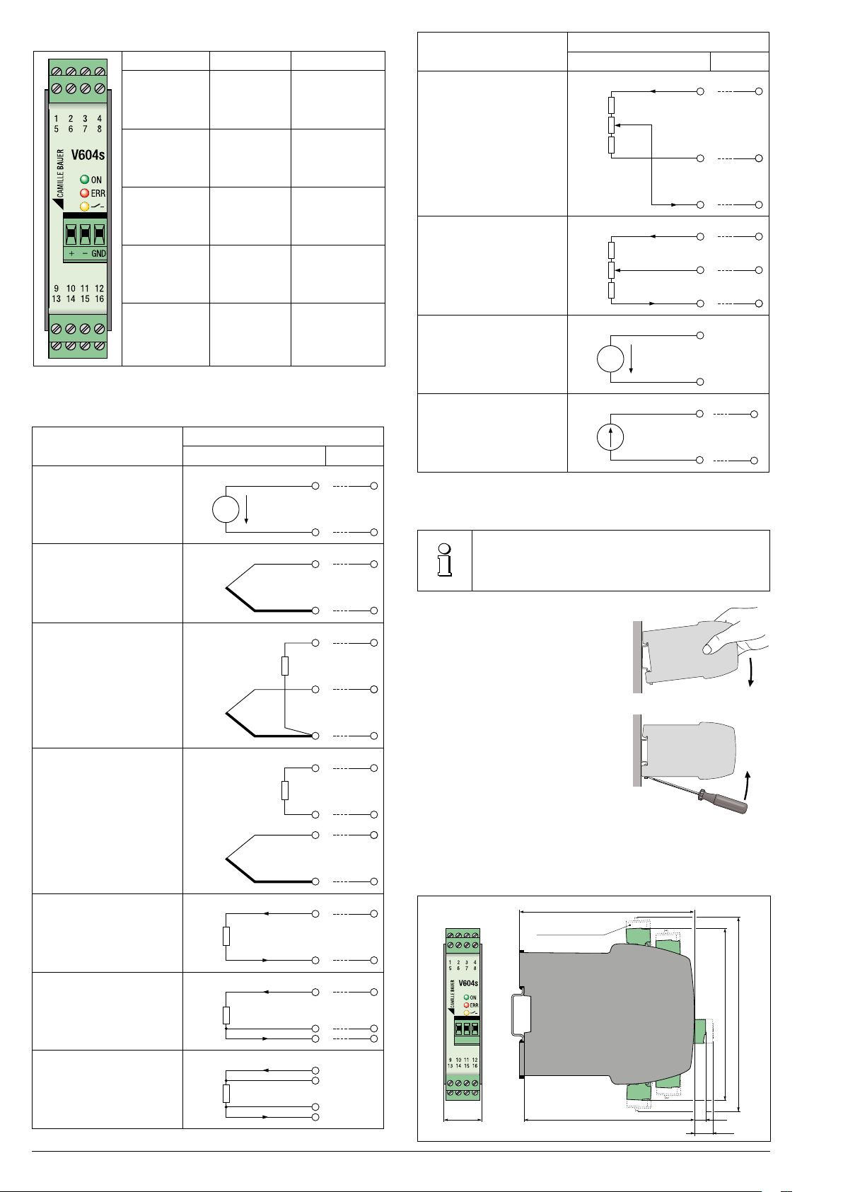
Anschlussbelegung
Kreis Klemmen Bemerkung
Messeingang 1 bis 8
Ausgang1
Ausgang 2
11 (+), 12 (–)
10 (+), 12 (–)
siehe Tabelle
«Anschluss der
Eingänge»
Messart
WiderstandsFerngeber WF
Beschaltung
Eingang 1 Eing. 2
1
Ra
0%
Rd
100%
Re
3
2
7
Relaiskontakt 9 (+), 13 (-)
Hilfsenergie
15 (+/~)
16 (–/~)
Bus-/
Programmier-
+, –, GND Frontstecker
anschluss
Tabelle: Anschluss der Eingänge
Messart
Gleichspannung mV
Thermoelement mit
externem Vergleichsstellenthermostat
oder
intern kompensiert
Thermoelement mit Pt100
an den Klemmen
am selben Eingang
Thermoelement mit Pt100
an den Klemmen
am anderen Eingang
Eingang 1 Eing. 2
+, -: Polarität
bei digitalem
Ausgang
Bei DC
Polarität
beachten
Beschaltung
3+
U [mV]
-
+
-
Pt100
+
-
Pt100
+
4
3
4
1
3
4
2
3
WiderstandsFerngeber WF-DIN
Gleichspannung V
(nur bei entsprechender
Geräteausführung,
nicht beim VQ604s)
Ra
Rd
Re
0%
100%
+
+
U [V]
-
4
1
3
4
6
4
5
8
2
7
8
6
Gleichstrom mA
(Eingang 2 nur bei entsprechender Geräteausführung)
7
-
I [mA]
4
4
Befestigung
8
7
8
2
7
8
1
48
7
Die Befestigung des SINEAX V604s, VB604s bzw. VQ604s erfolgt auf
einer Hutschiene.
Bei der Festlegung des Montageortes (Messortes) ist zu
beachten, dass die Grenzen der Betriebstemperatur nicht
überschritten werden:
– 25 und + 55 °C
Gehäuse auf Hutschiene
(EN 50 022) aufschnappen
(siehe Bild 1).
Bild 1
Demontage-Hinweis
Gehäuse gemäss Bild 2
von der Tragschiene
abnehmen.
Bild 2
Wartung
Der SINEAX V604s, VB604s bzw. VQ604s ist wartungsfrei.
Widerstands thermometer
oder
Widerstands-Messung
2-Leiter
Widerstands thermometer
oder
Widerstands-Messung
3-Leiter
Widerstands thermometer
oder
Widerstands-Messung
4-Leiter
RTD, R
RTD, R
RTD, R
-
4
1
1
3
4
1
2
3
4
8
2
84
2
7
8
Mass-Skizze
Zugfederklemmen
111
123
108
10822,5
7
13
2 Sicherheitshinweise V604s, VB604s und VQ604s Camille Bauer Metrawatt AG
Safety instructions which have to be observed without fail are
marked with the following symbols in these instruction:
Instruments may only be disposed of in a technically
appropriate manner!
Safety Instructions
Camille Bauer Metrawatt AG
Aargauerstrasse 7
CH-5610 Wohlen/Switzerland
Phone +41 56 618 21 11
Fax +41 56 618 21 21
info@cbmag.com
www.camillebauer.com
SINEAX V604s,
VB604s, VQ604s
Universal
Signal Converter
168 501-05 06.17
PM1000752 000 01
Read first, then …
The unobjectionable and safe operation presupposes that these safety instructions as well as
the operating instructions have been read and
understood!
This instrument should only be handled by respectively trained staff members who know the
instrument and are authorised to work on technical facilities.
The operation of the instrument must be stopped
if its safe operation (e.g. in case of visible damage)
is not possible any more. All connections are to
be disconnected in this case. The instrument is
to be forwarded to our plant or a service station
authorised by us.
Any warranty claim lapses if the instrument is
opened!
www.camillebauer.com/vx604s-en
Scope of delivery
1 SINEAX V604s, VB604s or VQ604s
1 Safety instructions 168 501
Brief description
SINEAX V604s, VB604s or VQ604s is a programmable multifunctional
transmitter for top-hat rail assembly. Input, output, bus and power supply are galvanically isolated.
Programming and communication are arranged via a Modbus interface.
Technical data
Measuring input
2 measuring inputs galvanically connected. In case of 2 sensors, observe
wiring instructions in the operating instructions!
Type of measurement Measuring range Minimum span
DC voltage [mV] –1000 … 1000 mV 2 mV
DC voltage [V] * –600 … 600 V
DC current [mA] –50 … 50 mA 0.2 mA
Resistance [Ω] 0 … 5000 Ω 8 Ω
RTD Pt100 –200 ... 850 °C 20 K
RTD Ni100 –60 ... 250 °C 15 K
TC Type B 0 ... 1820 °C 635 K
TC Type E –270 ... 1000 °C 34 K
TC Type J –210 ... 1200 °C 39 K
TC Type K –270 ... 1372 °C 50 K
TC Type L –200 ... 900 °C 38 K
TC Type N –270 ... 1300 °C 74 K
TC Type R –50 ... 1768 °C 259 K
TC Type S –50 ... 1768 °C 265 K
TC Type T –270 ... 400 °C 50 K
TC Type U –200 ... 600 °C 49 K
TC Type W5Re-W26Re 0 ... 2315 °C 135 K
TC Type W3Re-W25Re 0 ... 2315 °C 161 K
* not at VB604s and VQ604s
1)
In older device versions the measuring range is only -300 ... 300V. Before using,
please check the device version on the nameplate or with the CB-Manager SW
Camille Bauer Metrawatt AG Safety instructions V604s, VB604s and VQ604 3
1)
>1 V
Outputs
2 analog outputs, galvanically connected, common earth. Voltage or
current output of V604s/VB604s can be configured by software, the
VQ604s only in corresponding device type.
Direct
current
Direct
voltage
Relay contact output
Version relay
Contact 1 pole, normally open contact (NOC)
Switching capacity AC: 2A/250V, DC: 2A/30V
Version digital output*:
Contact Transistor, normally open contact (NOC)
Switching capacity max. 27VDC/27mA
Bus/ programming connection
Interface, protocol RS485, Modbus RTU
Power supply
Rated voltage U
24 … 230 V DC * ± 15%
100 … 230 V AC, 50/60 Hz ± 15%
Green LED = «Power ON» display
*
Range ±20 mA, burden voltage 12 V
Open circuit voltage < 20 V
Limitation max. ±22 mA
Range ±10 V,
load max.: V604s/VB604s: 20 mA, VQ604s: 0.02 mA
Current limitation approx. 30 mA
Limitation max. ±11 V
N
In case of a power supply voltage > 125 V DC, the power supply
circuit must contain an external fuse.
Tolerance
Electrical connections
Pluggable screw or spring cage terminals serve the connection of electric lines. They are suitable to wire cross-sections up to max. 2.5 mm2.
Ensure without fail that all lines are not under load
during connection!
Possibly impending danger from high voltages.
Please observe …
… that the data on the name plate are adhered to!
Arrange a marked, easily accessible switch in the vicinity of the
instrument to deactivation of the power supply.
As the power supply is switched on, the power supply source must
provide sufficient current (approx. 0.3 A) for a brief period of time.
Furthermore, the national provisions (e.g. for Germany VDE 0100
«Conditions concerning the erection of electric power installations
with rated voltages below 1000 V») are to be followed in the installation and selection of the material of electric lines!
Terminal layout
111
Circuit Terminal Remarks
Measuring
input
Output 1
Output 2
1 to 8
11 (+), 12 (–)
10 (+), 12 (–)
See table
«Connection of
inputs»
Type of measurement
Resistance
teletransmitter WF
Wiring
Input 1 Input 2
1
Ra
0%
Rd
100%
Re
3
2
7
Relay contact 9 (+), 13 (-)
Power supply
Bus/program.
connection
Table: Connection of inputs
Type of measurement
Direct voltage mV
Thermocouple with external
reference junction thermostat
or
internally compensated
Thermocouple with Pt100
at the terminals
at the same input
Thermocouple with Pt100
at the terminals
at the other input
+, -: Polarity on
digital output
15 (+/~)
16 (–/~)
Note polarity
at DC
+, –, GND Front plug
Wiring
Input 1 Input 2
3+
U [mV]
-
+
-
Pt100
+
-
Pt100
+
4
3
4
1
3
4
2
3
Resistanceteletransmitter WF-DIN
Direct voltage V
Ra
Rd
Re
0%
100%
4
1
3
4
+
6
8
2
7
8
(only in
corresponding
device type,
not at VQ604s)
U [V]
-
+
4
5
6
Direct current mA
(Input 2 only in
corresponding device type)
7
-
I [mA]
4
4
Fastening
8
7
8
2
7
Fastening of the SINEAX V604s, VB604s or VQ604s on a top-hat rail.
When determining the place of assembly (place of measurement), please observe that the operating temperature
limits are not exceeded:
– 25 and + 55 °C
Snap housing onto the
top-hat rail
(EN 50 022)
(see Picture 1).
Picture 1
Disassembly
8
1
48
7
Remove housing from
the mounting rail
according to Picture 2.
Picture 2
Maintenance
SINEAX V604s, VB604s or VQ604s does not require any maintenance
work.
4
1
1
3
4
1
2
3
4
8
2
84
2
7
8
Dimensional drawing
Spring cage terminal
123
108
10822.5
7
13
Resistance thermometer
or
resistance measurement
2-wire
Resistance thermometer
or
resistance measurement
3-wire
Resistance thermometer
or
resistance measurement
4-wire
-
RTD, R
RTD, R
RTD, R
4 Safety instructions V604s, VB604s and VQ604s Camille Bauer Metrawatt AG
 Loading...