

Camille Bauer SINEAX V604s Operating Instructions Manual

V604s Be Version 03 02.12
Operating instructions
SINEAX V604s
Programmable multifunctional
transmitter
Camille Bauer AG
Aargauerstrasse 7
CH-5610 Wohlen/Switzerland
Phone +41 56 618 21 11
Fax +41 56 618 21 21
info@camillebauer.com
www.camillebauer.com
2 Operating instructions V604s Be Camille Bauer
Operating instructions
Programmable multifunctional transmitter SINEAX V604s
First read, then …
The unobjectionable and safe operation presupposes that these operating instructions
have been read and understood!
Devices may only be disposed of in a professional manner!
Contents
1. Functional description .................................................2
2. Connection to a PC and communication via
CB-Manager ................................................................2
3. Block diagram ..............................................................3
4. Technical data .............................................................. 4
5. Signal fl ow ...................................................................7
6. Modbus interface ......................................................... 8
6.1 EIA-RS-485 Standard ...........................................8
6.2 Coding and addressing ........................................ 8
6.3 Mapping ...............................................................9
6.4 Device identifi cation .............................................9
6.5 Measured values ................................................ 10
6.6 Confi guration parameters ..................................11
7. Electric connections .................................................. 17
8. Dimensional drawing ................................................. 19
9. Accessories ............................................................... 19
10. Conformity declaration ..............................................19
1. Functional description
V604s is a multifunctional transmitter for top-hat rail assembly with the following main characteristics:
● Measurement of DC voltage, DC current, temperature
(RTD, TC) and resistance
● Sensor connection without any external jumpers
● 2 inputs (e.g. for sensor redundancy or difference
formation)
● 2 outputs (U and/or I)
● 2 inputs can be linked with each other and allocated
to the 2 outputs which enables calculations and
sensor monitoring (e.g. prognostic maintenance of
sensors)
●
System capability: Communication via Modbus
interface
● Freely programmable relay, e.g. for limit or alarm signalling
● AC/DC wide-range power supply unit
● Pluggable high-quality screw terminals
All settings of the instrument can be adapted to the measuring task by PC software. The software also serves visualising,
commissioning and service.
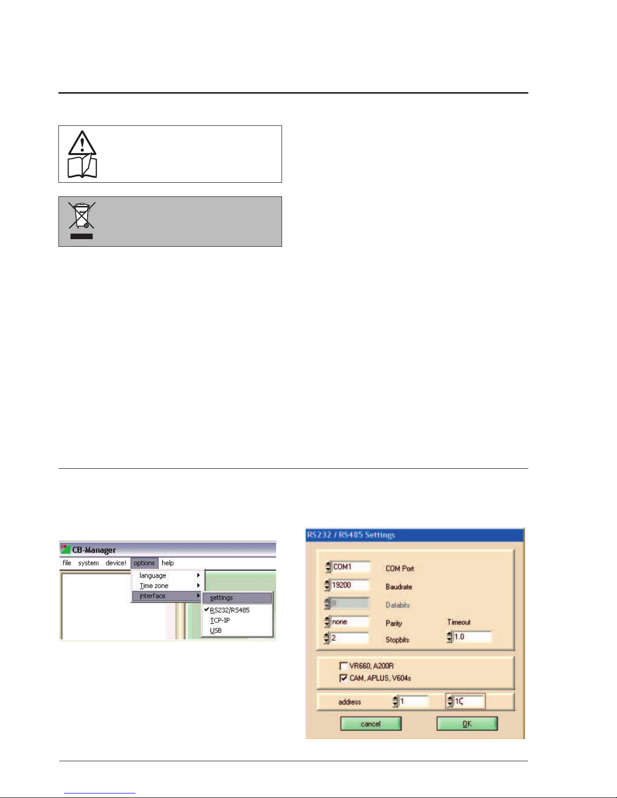
2. Connection of SINEAX V604s to a PC and communication via CB-Manager.
V604s communicates with a PC (CB-Manager) via an RS
232/RS485 interface and a MODBUS protocol.
Select the following settings in this respect:
Select the RS 232/ RS485 interface under Options / Interface.
This is also applicable if an RS485/USB converter is used
and the converter is connected to the computer via the
USB connection.
Subsequently, enter the following settings under Options /
Interface / Settings:
Camille Bauer Operating instructions V604s Be 3
D
A
D
3.7 kV
A
3.7 kV3.7 kV
Inputs
Power supply
Contact
A1+
A–
A2+
Bus
0.5 kV
2.3 kV
+
Tx
Rx
–
GND
Analogoutputs
μP
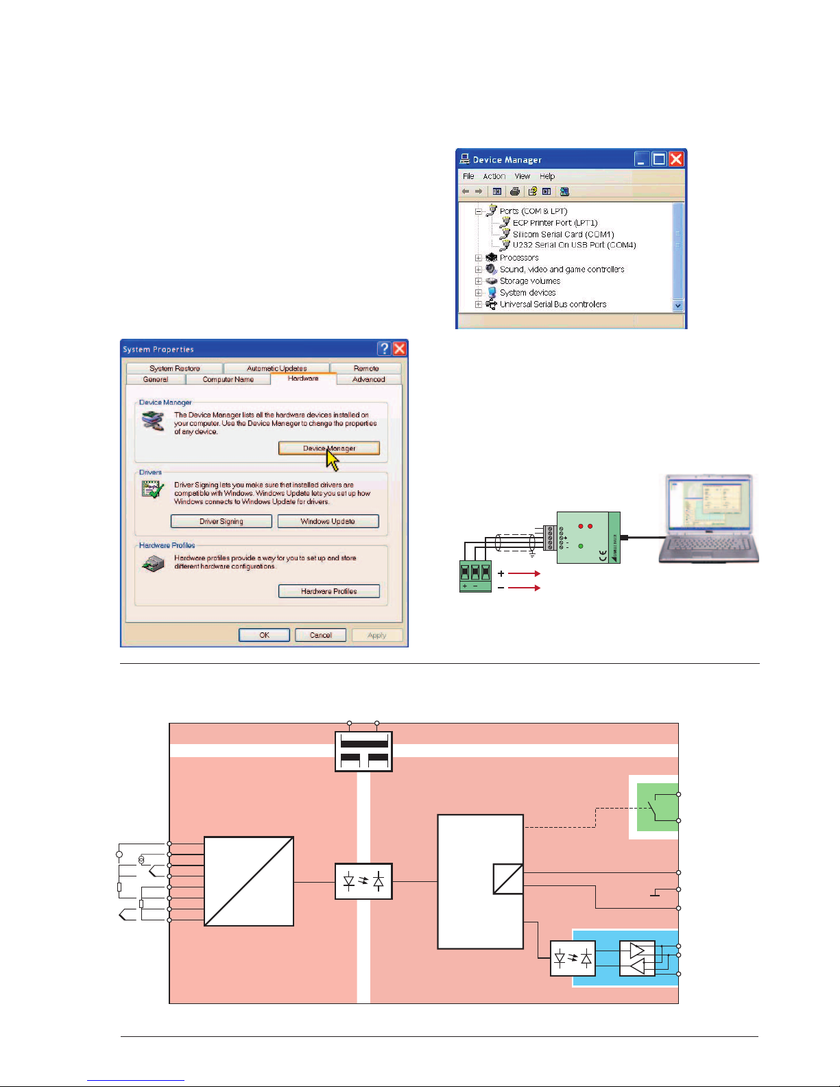
3. Block diagram
To determine which COM port has been allocated to
the RS485 converter (if required), please proceed as
follows:
The COM port of an external RS232 or RS485 converter
may be determined (and, if required, changed) via the
Windows system control.
Example for Windows XP: System control => System
This example shows the COM ports of a PCMCIA card
and a USB-RS232 converter:
- Silicom Serial Card: COM1
- USB-RS232 adapter: COM4
The existing COM ports are determined as the communication interface when starting the program and selecting
RS232/RS485. Only COM ports found are available for
selection.
Limiting the range of possible device addresses speeds
up the search of connected devices considerably.
Example: If only 2 devices are connected, it makes sense
to select the address range from 1 to 2.
All settings are stored as the program is terminated. If the
COM port is not available upon the next start of the program (e.g. because the converter has not been plugged in)
another valid interface is set.
If you use the Camille Bauer USB-RS485 converter
(Article Number 163189), the same is to be connected as
follows:
POWER
RS485
T1B1
HALF
A1 T2
Rx
USB / RS485
CONVERTER
Tx
T1
T2
USB
GND
A1
B1
4 Operating instructions V604s Be Camille Bauer
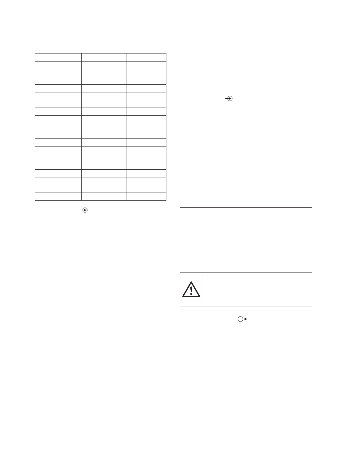
4. Technical data
Table 1: Input variables, measuring ranges
Measurement type Measuring range Minimum span
DC voltage [mV] –1000 … 1000 mV 2 mV
DC voltage [V] –300 … 300 V >1 V
DC current [mA] –50 … 50 mA 0,2 mA
Resistance [Ω] 0 … 5000 Ω 8 Ω
RTD Pt100 –200 ... 850 °C 20 K
RTD Ni100 –60 ... 250 °C 15 K
TC Type B 0 ... 1820 °C 635 K
TC Type E –270 ... 1000 °C 34 K
TC Type J –210 ... 1200 °C 39 K
TC Type K –270 ... 1372 °C 50 K
TC Type L –200 ... 900 °C 38 K
TC Type N –270 ... 1300 °C 74 K
TC Type R –50 ... 1768 °C 259 K
TC Type S –50 ... 1768 °C 265 K
TC Type T –270 ... 400 °C 50 K
TC Type U –200 ... 600 °C 49 K
TC TypeW5Re-26Re 0 ... 2315 °C 135 K
TC TypeW3Re-25Re 0 ... 2315 °C 161 K
Measuring input 1
Direct voltage
Measuring range mV For limits see Table 1
Ri > 10 MΩ, continuous,
overload max. ±1200 mV
Measuring range V For limits see Table 1
(only in corresponding Ri = 1.4 MΩ, continuous,
device type) overload max. ±300 V
Direct current
Measuring range mA For limits see Table 1
Ri = 11 Ω, continuous,
overload max. ±50 mA
Resistance thermometer RTD
Resistance measurement
types Pt100 (IEC 60751),
adjustable Pt20…Pt1000
Ni100 (DIN 43760),
adjustable Ni50…Ni1000
Measuring range limits See Table 1
Wiring 2, 3 or 4-wire connection
Measuring current 0.2 mA
Line resistance 30 Ω per line,
in 2-wire connection adjustable
or calibratable
Thermocouples TC
Thermocouples Type B, E, J, K, N, R, S, T
(IEC 60 584-1)
Type L, U (DIN 43760)
Type W5Re-W26Re, W3Re-
W25Re (ASTM E988-90)
Measuring range limits See Table 1
Cold junction
compensation Internal (with installed Pt100),
with Pt100 on terminals or
external with reference junction
–20…70 °C
Resistance measurement, teletransmitter, potentiometer
Measuring range limits See Table 1
Wiring 2, 3 or 4-wire connection
Resistance teletransm. Type WF and WF DIN
Measuring current 0.2 mA
Line resistance 30 Ω per line,
in 2-wire connection adjustable or
calibratable
Measuring input 2
Direct current
Measuring range mA Same as Measuring input 1
(only in corresponding
device type)
Direct voltage
Measuring range mV Same as Measuring input 1
Resistance thermometer RTD
Same as Measuring input 1 except:
Wiring 2 or 3-wire connection
Thermocouples TC
Same as Measuring input 1
Resistance measurement, teletransmitter, potentiometer
Same as Measuring input 1 except:
Wiring 2 or 3-wire connection
Please note:
The following device types are available:
a) V604s with measuring input for 1x direct current [mA]
and 1x high direct voltage [V]
The direct voltage [V] and direct current [mA] measuring
methods can be allocated to Input 1 or Input 2 here.
b) V604s with measuring input for 2x direct current [mA]
The different device types are fi rm and cannot be repro-
grammed!
Measuring inputs 1 and 2 are galvanically
connected. If 2 input sensors or input variables are used, observe combination options
in Table 3 (page19) and circuit instructions
(page 18)!
Analog outputs 1 and 2
The two outputs are galvanically connected and have
a common earth. Voltage and current output softwareconfi gurable.
Direct current
Output range ± 20 mA,
range may be freely set
Burden voltage max. 12 V
Open circuit voltage < 20 V
Limit Adjustable, max. ±22 mA
Residual ripple <1% pp related to 20 mA
Direct Voltage
Output range ± 10 V,
range may be freely set
Load max. 20 mA
Current limit Approx. 30 mA
Limit Adjustable, max. ±11 V
Residual ripple <1% pp related to 10 V

Camille Bauer Operating instructions V604s Be 5
Output settings
Limit
Gain/offset trimming
Inversion
Relay contact output
Contact 1 pole, normally open contact
Switching capacity AC: 2 A / 250 V AC
DC: 2 A / 30 V
Bus/programming connection
Interface, protocol RS-485, Modbus RTU
Baudrate 9,6...115,2 kBaud, adjustable
Transmission behaviour
Measured variables
for the outputs • Input 1
• Input 2
• Input 1 + Input 2
• Input 1 – Input 2
• Input 2 – Input 1
• Input 1 · Input 2
• Minimum value, maximum
value
or mean value of Input 1
and Input 2
• Sensor redundancy
Input 1 or Input 2
Transmission function Linear,
user-specifi c via
basic value table
(24 basic values per measured
variable)
Settling time: Adjustable 1…30 s
Limit values and monitoring
Number of limit values 2
Measured variables for
limit values • Input 1
• Input 2
• Measured variable for outputs
• Input 1 – Input 2
(e.g. drift monitoring in case of
2 sensors)
• Input 2 – Input 1
(e.g. drift monitoring in case of
2 sensors)
Functions Absolute amount
Gradient dx/dt (e.g. temperature
gradient monitoring)
Time delay Adjustable 0…3600 s
Signaling Relay contact, alarm LED,
Status 1
Sensor breakage and
short circuit monitoring measuring input
Signalling Relay contact, alarm LED,
Status 1
Output value in case of a fault
Other monitoring operations
Drift monitoring Monitoring of measured value
between 2 input sensors for a
certain period of time (e.g. due to
different sensor response times).
If this time is exceeded, an alarm
is signalled.
(See Limit values 1 and 2)
Sensor redundancy Measurement with 2 temperature
sensors; if Sensor 1 fails (fault)
Sensor 2 is activated for bridging (see measuring variable for
outputs).
Alarm signalling
Relay contact With closed contact,
the yellow LED shines,
invertible
Alarm LED
Time delay Adjustable 0…60 s
Output value
in case of a fault For sensor breakage and short
circuit, value adjustable –10…
110%
Power supply
Rated voltage UN Tolerance
24…230 V DC * ±15%
100…230 V AC, 45…400 Hz ±15%
* In case of a power supply voltage >125 V DC, the power
supply circuit must contain an external fuse
Power consumption >3 W or 7 VA
Displays at the instrument
LED Color Function
ON green Power on
green fl ashing Communication activ
ERR red Alarm
yellow Relay on
Confi guration, programming
Operation with PC software «CB-Manager»
Accuracies (according to EN/IEC 60770-1)
Reference conditions
Ambient temperature 23 °C ± 2 K
Power supply 24 V DC
Reference value Span
Settings Input 1: Direct voltage mV,
0…1000 mV
Output 1: 4…20 mA, burden
resistance 300 Ω
Mains frequency 50 Hz,
Setting time 1 s
Input 2, output 2, relay, monitor-
ing off or not active, for voltage
output: range 0...10 V, burden
resistance 2kΩ
Installation position Vertically, detached
Basic accuracy
At reference conditions ±0.1%
Other types of measurement and input ranges:
RTD Pt100, Ni100 ±0.1% ±0.2 K
Resistance measurement ±0,1% ±0.1 Ω
TC Type K, E, J, T, N, L, U ±0.1% ±0.4 K,
measurement value > –100 °C
TC Type R, S ±0.1% ±2.4 K
TC Type B ±0.1% ±2.4 K,
measurement value > 300°C
6 Operating instructions V604s Be Camille Bauer
TC W5Re-W26Re,
W3Re-W25Re ±0.1% ±2.0 K
DC voltage mV ±0.1% ±0.015 mV
DC voltage V ±0.1% ±0.0045 V
DC current mA ±0.1% ±0.0015 mA
Additional error (additive)
High range minimum value
(Minimum value >40%
of maximum value): ±0.1% of maximum value
Small output range ±0.1% * (reference range / new
range)
Cold junction
compensation internal ±3 K
Infl uencing factors
Ambient temperature ±0.1% per 10 K at reference con-
ditions
other settings: basic accuracy
and additional errors per 10 K
Long-term drift ±0.1%
Common mode/
series mode infl uence ±0.2%
Ambient conditions
Operating temperature –25 … +55 °C
Storage temperature –40 … +70 °C
Relative humidity ≤75%, no dew
Range of utilisation Internal room up to 2000 m above
sea level
Installation details
Design Top-hat rail housing U4
Combustibility class V-0
according to UL 94
Dimensions See dimensional drawing
Assembly For snap-on fastening on top-hat
rail (35 x 15 mm or 35 x 7.5 mm)
according to EN 50022
Terminals Pluggable, 2.5 mm
2
Weight 0.14 kg
Product safety, regulations
Electromagnetic
compatibility
EN 61000-6-2 / 61000-6-4
Ingress protection (acc.
IEC 529 or EN 60529)
Housing IP 40
terminal IP20
Electric design Acc. IEC or EN 61010
Degree of pollution 2
Between power sup-
ply and all circuits and
between the measuring input (1 + 2) and all
circuits
Reinforced insulation
overvoltage category III
Working voltage 300 V
Test voltage 3.7 kV AC rms
Between output
(1 + 2) and relay contact
Reinforced insulation
overvoltage category II
Working voltage 300 V
Test voltage 2.3 kV AC rms
Between output (1 + 2)
and the bus connection
Functional insulation
Working voltage <50 V
Test voltage 0.5 kV AC rms
Environmental tests EN 60068-2-1/-2/-3
EN 60068-2-27 Shock: 50g,
11ms, sawtooth, half-sine
EN 60068-2-6 Vibration:
0.15mm/2g, 10...150Hz,
10 cycles
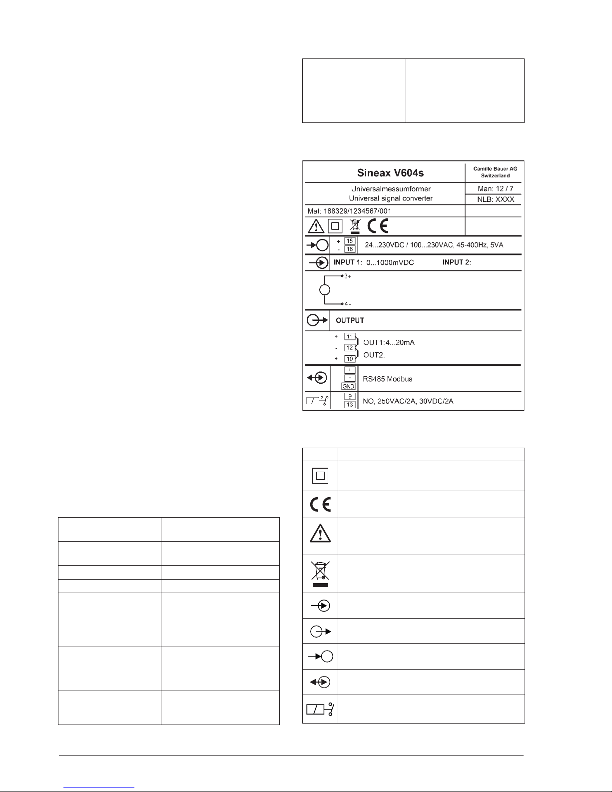
Type label
Explanation of symbols on the type label
Symbol Meaning
Double insulation, device of protection class 2
CE conformity mark. The device fulfi lls the
requirements of the applicable EG directives
Caution!
General hazard point.
Read the operating instructions.
The instruments must be only be disposed of
in the correct way!
General symbol: Input
General symbol: Output
General symbol: Power supply
General symbol: Communication
General symbol: Relay
 Loading...