

Camille Bauer SINEAX TI 807-5 Operating Instructions Manual

14
Passive
DC signal isolator
SINEAX TI 807-5
TI 807-5 Be 999766-01 08.05
Fig. 1
Fig. 12. SINEAX TI 807-5.... (housing N17) clipped onto a top-hat rail
(35 × 7.5 or 35 × 15 mm, acc. to EN 50022).
10. Dimensional drawings
107.1
84.5
17.5
+0.5
+0
The following symbols in the Operating Instructions indicate safety
precautions which must be strictly observed:
3. Brief description
The signal isolator SINEAX TI 807 serves to electrically insulate one
analogue DC signal in the range 0...20 mA which depending on version
is then converted to a current or voltage signal (0...20 mA or 0...10 V). It
does not require a separate power supply.
4. Specification and ordering information
Order Code 807 – 5 1
1. Mechanical design
Housing N17 5
2. Version
Standard (non-Ex) 1
Input
and output signals
non-intrinsically safe
[EEx ib] IIC 2
Input signal
intrinsically safe
[EEx ia] IIC 6
Output signal
intrinsically safe
3. Number of isolation
and transmission channels
1 channel (interface) 1
4. Output signal A
0 ... 20 mA 0
0 ... 10 V 1
5. Climatic rating
Standard climatic rating 0
Improved climatic rating 1
Contents
1. Read first and then … .................................................................. 1
2. Scope of supply ............................................................................ 1
3. Brief description ............................................................................1
4. Specification and ordering information .........................................1
5. Technical data ...............................................................................1
6. Mounting ....................................................................................... 2
7. Electrical connections ...................................................................3
8. Commissioning and maintenance ................................................. 3
9. Releasing the signal isolator .......................................................... 3
10. Dimensional drawings ...................................................................4
11. Declaration of conformity ..............................................................4
5. Technical data
Input signal E
DC current signal IE: 0...20 mA
Max. permissible current: 50 mA
Voltage limiter: Non-Ex version: 27 V ±5%
(with zener diode)
Ex version: 18 V, ±5%
112.1
84.5
5.8
60
Adapter Adapter
17.5
+0.5
+0
Fig. 13. SINEAX TI 807-5.... (housing N17) with adapter for wall mounting.
1. Read first and then …
The proper and safe operation of the device assumes
that the Operating Instructions are read carefully and
the safety warnings given in the sections
6. Mounting
7. Electrical connections
are
observed.
The device should only be handled by appropriately
trained personnel who are familiar with it and authorised
to work in electrical installations.
Unauthorized repair or alteration of the unit invalidates
the warranty!
2. Scope of supply
Signal isolator (Fig. 1)
1 Adapter (Fig. 1) for wall mounting
1 copy Operating Instructions (Fig. 2) in English, French, German
1 Ex approval (Fig. 2), only for Ex version devices
Fig. 2
Operating Instructions
Camille Bauer LTD
Aargauerstrasse 7
CH-5610 Wohlen/Switzerland
Phone +41 56 618 21 11
Fax +41 56 618 35 35
e-mail: info@camillebauer.com
http://www.camillebauer.com
The instruments must only be disposed of in the
correct way!
11. Declaration of conformity
Die se Erk lär un g b esc he ini gt die Ü ber ein sti mm ung mi t den This de cla rat ion c ert ifi es com pli anc e w ith th e a bov e m ent ion ed
gena nnt en Ri cht lin ien , b ein hal tet je do ch kei ne Zus ich eru ng dire cti ves bu t d oes no t i ncl ude a pr ope rty as sur anc e.
von Ei gen sch aft en. D ie Sic her he its hin wei se de r m itg eli efe rt en The saf ety no tes gi ven in th e p rod uct do cum ent ati ons , w hic h a re
Prod uktd oku ment ati onen si nd zu b eac hte n. part of the su ppl y, must be ob ser ved.
EG - KON FORM ITÄT SERK LÄRU NG
DEC LARA TION OF CO NFOR MITY
Dok umen t-Nr ./ TI80 7.DOC
Doc ume nt.N o.:
Her stel ler/ Ca mil le Bau er AG
Man ufact urer : Swi tzer lan d
Ans chr ift / Aarga uers tra sse 7
Add res s: CH- 561 0 W ohle n
Pro dukt beze ichn ung/ Pas siv er DC- Si gnal tre nne r
Pro duct na me: Pas ive DC sign al isol ator
Typ / T ype: SIN EAX TI 807
Das be zeic hnet e P rodu kt stim mt mit den Vor sch rift en f olg ende r E urop äisc her Ric htli nie n üb erei n,
nac hgewi esen du rch die Einh altu ng f olge nder Nor men:
The abo ve menti oned pr oduc t ha s be en manu fact ured acc ordi ng t o t he r egul atio ns o f t he f ollo wing
Eur opea n di rect ives pr oven thr ough co mplia nce wit h th e f ollo wing sta ndar ds:
Nr. / No. R icht lini e / Dir ecti ve
89/ 336 /EW G
89/ 336 /EE C
Ele ktr omag net isch e V ert rägl ich keit - EMV - Ric htli nie
Ele ctro mag neti c c ompa tibi lit y - EMC dir ecti ve
EM V /
EM C
Fac hgru ndno rm /
Gen eric Sta ndar d
Mess verf ahre n /
Mea sure ment me thod s
Stö raus sen dung /
Emi ssi on
EN 50 081-2 : 1993 EN 5501 1 : 199 2
Stö rfe sti gkei t /
Imm uni ty
EN 50 082-2 : 1994 IEC 100 0-4-2 : 1991
IEC 100 0-4-3 : 1995
IEC 100 0-4-4 : 1988
IEC 100 0-4-6 : 1995
Nr. / No. R icht lini e / Dir ecti ve
73/ 23/ EWG
73/ 23/ EEC
Ele ktri sch e Be tri ebsm itte l z ur Verw endu ng inne rhal b b est immt er Span nung sgre nzen - Nied ersp annu ngsr icht lin ie - CE -Ken nzei chnu ng : 95
Ele ctri cal equ ipme nt for use wit hin cer tain vo ltag e l imit s - Low Vo ltag e D ire
c-
tiv e - Att achm ent of CE mar k : 95
EN/ Norm /Sta ndar d IEC /Nor m/St anda rd
EN 61 010-1 : 1993 IEC 101 0-1 : 1 990 + A 1 : 199 2
Die ex plos ion sges chü tzte Au sfü hrun g d iese s P rod ukts st imm t mi t d er Eur opäi sch en
Ric htli nie 94/ 9/EG üb erei n.
The exp losi on prot ecte d v aria nt o f t his prod uct has bee n m anuf actu red acc ordi ng t he
Eur opean di recti ve 94/9.
Ort , D atu m /
Pla ce, dat e: Woh len, den 5. Jun i 1 999
Unt ersc hri ft / M.U lri ch
Sig natu re:
Lei ter Ent wic klu ng
32
Output signal A
(DC current or DC voltage)
DC current signal I
A
: 0...20 mA
Voltage drop U
V
:
< 2.8 V for the standard (non-Ex) version
< 4.7 V for Ex versions
(input signal “intrinsically safe”)
< 6.3 V for Ex versions
(output signal “intrinsically safe”)
Max. burden:
1000 Ω for the standard (non-Ex) version
500 Ω for Ex versions
(input signal “intrinsically safe”)
500 Ω for Ex versions
(output signal “intrinsically safe”)
Limit: Approx. 40 mA
Residual ripple: <20 mV ss
Time constant: Approx. 3 ms
Response time
1
acc. to IEC 770: Approx. 15 ms
DC voltage signal UA: 0...10 V
Voltage drop U
V
:
< 2.8 V for the standard (non-Ex) version
< 4.7 V for Ex versions
(input signal “intrinsically safe”)
< 6.3 V for Ex versions
(output signal “intrinsically safe”)
Internal resistance: 500
Ω
Limit:
< 26 V for the standard (non-Ex) version
< 16 V for Ex versions
(input signal “intrinsically safe”)
< 16 V for Ex versions
(output signal “intrinsically safe”)
Residual ripple: < 20 mV ss
Time constant: Approx. 3 ms
Response time
1
acc. to IEC 770: Approx. 15 ms
Accuracy data
Error limits: < ±0.1%
2
(Reference value 20 mA including linearity
error)
< ±0.2 %
3
(Reference value 10 V including linearity
error)
Ambient conditions
Operating temperature: –25 to +55 °C
–20 to +55 °C
(Ex versions: input or output signal “intrinsi
-
cally safe”)
Storage temperature: –40 to +70 °C
Annual mean
relative humidity:
≤75% standard climatic rating
≤95% improved climatic rating
Seismic test: 5 g, <200 Hz, 2 h in each of 3 directions
Shock: 50 g, 10 shocks in each of 3 directions
Altitude: 2000 m max.
Indoor use statement!
6. Mounting
The SINEAX TI 807 can be mounted either on a top-hat rail or directly
onto a wall or mounting plate using the adapter (standard accessory).
Make sure that the ambient temperature stays within
the permissible limits:
–25 and +55 °C for standard instruments
–20 and +55 °C for instruments in Ex version!
6.1 Top-hat rail mounting
Simply clip the device onto the top-hat rail (EN 50 022) (see Fig. 3).
7. Electrical connections
The electrical connections are made to screw terminals which are easily
accessible from the front of the signal isolator (see Fig. 8 and 9) and can
accommodate wire gauges up to 2.5 mm2.
Make sure that the cables are not live when making
the connections!
In the case of “Intrinsically safe” [EEx ib] IIC or
[EEx ia] IIC explosionproof versions, the supple
mentary information given on the type examination
certification, the EN 60 079-14 and also local regula
tions applicable to electrical installations in explosion
hazard areas must be taken into account.
Fig. 6. Mounting on the adapter.
1
This is the time which transpires before the output signal reaches the error limit
of 1% for a step change of the input signal from 0
90%.
2
With current signal and RA = 250 Ω
3
With voltage signal
Fig. 3. Mounting on top-hat rails 35 × 15 or 35 × 7.5 mm.
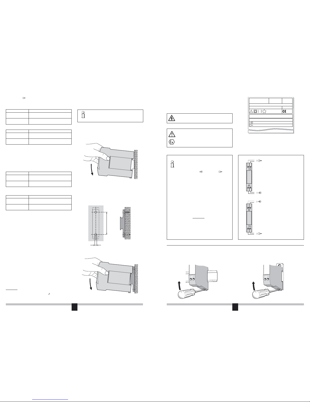
Connect the input E and output A leads according to Figures 8 and 9.
Signal isolator in housing N17 with one isolation and transmission
channel
Fig. 11Fig. 10
Note that, ...
... the required electrical insulation and transmission
data agree with the data on the nameplate of the
SINEAX TI 807 (
input signal and output
signal, see Fig. 7)!
... in the case of a signal isolator with current outputs
0...20 mA, the total resistance of the external
leads (receiver plus leads) does not exceed the
maximum burden of 1000 Ω (non-Ex version) or
500 Ω (Ex version)! See “Output signal” in Section
5 “Technical data”!
... in the case of a signal isolator with voltage output
0...10 V, the external receiver connected across
the output has a sufficiently high internal resist
-
ance R
iA in relation to the SINEAX TI 807 output
impedance of 500
Ω! See “Output signal” in Section
5 “Technical data”!
The error due to RiA is:
F [%] =
... the input and output cables should be twisted
pairs and run as far as possible away from heavy
current cables!
4
+
3
–
–
1
+
2
–
+
A
–
+
E
4
+
3
–
–
1
+
2
–
+
A
–
+
E
SINEAX TI 807
Typ: 807-5233
No.: 000000/XXXXXX
Passive DC signal isolator
Passiver DC-Signaltr
enner
1997 NLBxxx
Tamb 55 °C
0…20 mA
0…20 mA
0,2
4
Camille Bauer AG
Aargauerstr.
7
CH-5610 Wohlen
Switzerland
Fig. 7. Example of a nameplate.
5.8
60
Fig. 4. Drilling pattern.
6.2 Wall mounting
Drill 2 holes in the wall or panel as shown in the drilling pattern (Fig. 4).
Now secure the adapter (standard accessory) to the wall or panel using
two 5 mm diameter screws (Fig. 5). Clip the device onto the adapter
(Fig. 6).
–
1
+
2
–
1
+
2
8. Commissioning and maintenance
The device is in operation as soon as the input signal E is connected.
The signal isolator requires no maintenance.
Fig. 8.
SINEAX TI 807-511..,
Standard (non-Ex) version
and
SINEAX TI 807-561.. and TI 807-581..,
Ex version
(output signal A “intrinsically safe”)
Fig. 9.
SINEAX TI 807-521.. and TI 807-541..,
Ex version
(input signal E “intrinsically safe”)
Fig. 5. Adapter mounted on wall.
500 [Ω] · 100
RiA [Ω]
9. Releasing the signal isolator
Release the signal isolator from a top-hat rail as shown in Fig. 10 or from
the adapter as shown in Fig. 11.
 Loading...