

Camille Bauer SINEAX DM5000, SINEAX AM3000 Device Handbook
in Bearbeitung
Camille Bauer Metrawatt AG
https://www.camillebauer.com
Device handbook
SINEAX DM5000
Operating Instructions SINEAX DM5000 (2019-06)
Aargauerstrasse 7
CH-5610 Wohlen / Switzerland
Phone: +41 56 618 21 11
Telefax: +41 56 618 35 35
E-Mail: info@cbmag.com
Legal information

Warning notices
In this document warning notices are used, which you have to observe to ensure personal safety and to prevent
damage to property. Depending on the degree of danger the following symbols are used:
If the warning notice is not followed death or severe personal injury
will result.
If the warning notice is not followed damage to property or severe
personal injury may result.
If the warning notice is not followed the device may be damaged or
may not fulfill the expected functionality.
Qualified personnel
The product described in this document may be handled by personnel only, which is qualified for the respective
task. Qualified personnel have the training and experience to identify risks and potential hazards when working
with the product. Qualified personnel are also able to understand and follow the given safety and warning
notices.
Intended use
The product described in this document may be used only for the application specified. The maximum electrical
supply data and ambient conditions specified in the technical data section must be adhered. For the perfect and
safe operation of the device proper transport and storage as well as professional assembly, installation,
handling and maintenance are required.
Disclaimer of liability
The content of this document has been reviewed to ensure correctness. Nevertheless it may contain errors or
inconsistencies and we cannot guarantee completeness and correctness. This is especially true for different
language versions of this document. This document is regularly reviewed and updated. Necessary corrections
will be included in subsequent version and are available via our webpage https://www.camillebauer.com
Feedback
If you detect errors in this document or if there is necessary information missing, please inform us via e-mail to:
customer-support@camillebauer.com
.
PM 1001484 000 08 Device handbook SINEAX DM5000 2/96

Contents
1. Introduction ................................................................................................................................. 5
1.1 Purpose of this document ........................................................................................................ 5
1.2 Scope of supply ....................................................................................................................... 5
1.3 Further documents .................................................................................................................. 5
2. Safety notes ................................................................................................................................. 6
3. Device overview .......................................................................................................................... 6
3.1 Brief description ....................................................................................................................... 6
3.2 Available measurement data ................................................................................................... 6
4. Mechanical mounting .................................................................................................................. 7
5. Electrical connections ................................................................................................................ 8
5.1 General safety notes ............................................................................................................... 8
5.2 Terminal assignments of the I/O extensions ............................................................................ 9
5.3 Current input connections ........................................................................................................ 9
5.4 Possible cross sections and tightening torques ..................................................................... 10
5.5 Inputs .................................................................................................................................... 10
5.6 Power supply ......................................................................................................................... 22
5.7 Relays ................................................................................................................................... 22
5.8 Digital inputs .......................................................................................................................... 22
5.9 Digital outputs ....................................................................................................................... 23
5.10 Analog outputs ..................................................................................................................... 24
5.11 Modbus interface RS485 ....................................................................................................... 24
5.12 Fault current detection ........................................................................................................... 25
5.13 Temperature inputs ............................................................................................................... 27
5.14 Uninterruptible power supply (UPS) ..................................................................................... 27
5.15 GPS time synchronization ................................................................................................. 28
6. Commissioning ......................................................................................................................... 30
6.1 Operating LED....................................................................................................................... 30
6.2 Parametrization of the device functionality ............................................................................. 31
6.3 Installation check ................................................................................................................... 31
6.4 Ethernet installation ............................................................................................................... 33
6.4.1 Settings ......................................................................................................................... 33
6.4.2 Connection of the standard interface ............................................................................. 35
6.4.3 Connection of the IEC61850 interface ........................................................................... 36
6.4.4 Connection of the PROFINET interface ......................................................................... 36
6.4.5 MAC addresses ............................................................................................................. 37
6.4.6 Communication tests ..................................................................................................... 37
6.4.7 Resetting the communication settings ............................................................................ 38
6.5 IEC 61850 interface ............................................................................................................... 38
6.6 PROFINET IO interface ......................................................................................................... 38
6.6.1 General stations description file (GSD) .......................................................................... 38
6.6.2 Parameterization of the device....................................................................................... 39
6.6.3 Validity of measurements ............................................................................................... 41
6.6.4 PROFINET state ............................................................................................................ 41
6.7 Simulation of analog / digital outputs ..................................................................................... 42
6.8 Security system ..................................................................................................................... 42
6.8.1 Protection against device data changing ........................................................................ 42
6.8.2 Secure communication using HTTPS ............................................................................ 43
6.8.3 Whitelisting clients ......................................................................................................... 44
PM 1001484 000 08 Device handbook SINEAX DM5000 3/96

7. Operating the device ................................................................................................................ 45
7.1 Operating elements ............................................................................................................... 45
7.2 Selecting the information to display ....................................................................................... 45
7.3 Measurement displays and used symbols ............................................................................. 46
7.4 Resetting measurement data ................................................................................................ 48
7.5 Configuration ........................................................................................................................ 48
7.5.1 Configuration at the device .............................................................................................. 48
7.5.2 Configuration via web browser ........................................................................................ 50
7.6 Alarming................................................................................................................................ 52
7.6.1 Limit values on base quantities ...................................................................................... 52
7.6.2 Monitoring fault-currents ................................................................................................ 53
7.6.3 Temperature monitoring ................................................................................................ 54
7.6.4 Monitoring functions ...................................................................................................... 55
7.6.5 Summary alarm ............................................................................................................. 56
7.7 Data recording ...................................................................................................................... 57
7.7.1 Periodical data .............................................................................................................. 57
7.7.2 Events ........................................................................................................................... 60
7.7.3 Disturbance recorder ..................................................................................................... 61
7.8 Timeouts ............................................................................................................................... 63
8. Service, maintenance and disposal ......................................................................................... 64
8.1 Calibration and new adjustment ............................................................................................ 64
8.2 Cleaning................................................................................................................................ 64
8.3 Battery .................................................................................................................................. 64
8.4 Disposal ................................................................................................................................ 64
9. Technical data ........................................................................................................................... 65
Annex .............................................................................................................................................. 72
A Description of measured quantities ........................................................................................ 72
A1 Basic measurements............................................................................................................. 72
A2 Harmonic analysis ................................................................................................................. 76
A3 System imbalance ................................................................................................................. 77
A4 Mean values and trend .......................................................................................................... 78
A5 Meters ................................................................................................................................... 79
B Display matrices ....................................................................................................................... 80
B0 Used abbreviations for the measurements ............................................................................ 80
B1 Display matrices for single phase system .............................................................................. 85
B2 Display matrices for split-phase (two-phase) systems ........................................................... 86
B3 Display matrices for 3-wire system, balanced load ................................................................ 87
B4 Display matrices for 3-wire system, balanced load, phase shift ............................................. 88
B5 Display matrices for 3-wire systems, unbalanced load .......................................................... 89
B6 Display matrices for 3-wire systems, unbalanced load, Aron ................................................. 90
B7 Display matrices for 4-wire system, balanced load ................................................................ 91
B8 Display matrices for 4-wire systems, unbalanced load .......................................................... 92
B9 Display matrices for 4-wire system, unbalanced load, Open-Y .............................................. 93
C Logic functions ......................................................................................................................... 94
D FCC statement .......................................................................................................................... 95
INDEX .............................................................................................................................................. 96
PM 1001484 000 08 Device handbook SINEAX DM5000 4/96

1. Introduction
1.1 Purpose of this document
This document describes the universal measurement device for heavy-current quantities SINEAX
DM5000. It is intended to be used by:
• Installation personnel and commissioning engineers
• Service and maintenance personnel
• Planners
Scope
This handbook is valid for all hardware versions of the DM5000. Some of the functions described in this
document are available only, if the necessary optional components are included in the device.
Required knowledge
A general knowledge in the field of electrical engineering is required. For assembly and installation of the
device knowledge of applicable national safety regulations and installation standard is required.
1.2 Scope of supply
• Measurement device SINEAX DM5000
• Safety instructions (multiple languages)
• Battery pack (optional, for devices with UPS only)
1.3 Further documents
The following documents are provided electronically via https://www.camillebauer.com/dm5000-en :
• Safety instructions SINEAX DM5000
• Data sheet SINEAX DM5000
• Modbus basics: General description of the communication protocol
• Modbus interface SINEAX DM5000: Register description for Modbus communication
• IEC61850 interface SINEAX AMx000/DM5000, LINAX PQx000, CENTRAX CUx000
• Camille Bauer certificate for encrypted HTTPS communication
PM 1001484 000 08 Device handbook SINEAX DM5000 5/96

2. Safety notes
Device may only be disposed in a professional manner!
The installation and commissioning should only be carried out by trained personnel.
Check the following points before commissioning:
– that the maximum values for all the connections are not exceeded, see "Technical data"
section,
– that the connection wires are not damaged, and that they are not live during wiring,
– that the power flow direction and the phase rotation are correct.
The instrument must be taken out of service if safe operation is no longer possible (e.g. visible
damage). In this case, all the connections must be switched off. The instrument must be
returned to the factory or to an authorized service dealer.
It is forbidden to open the housing and to make modifications to the instrument. The instrument
is not equipped with an integrated circuit breaker. During installation check that a labeled switch
is installed and that it can easily be reached by the operators.
Unauthorized repair or alteration of the unit invalidates the warranty.
3. Device overview
3.1 Brief description
The SINEAX DM5000 is a comprehensive instrument for the universal measurement and monitoring in
power systems. A full parameterization of all functions of the device is possible directly at the device (for
versions with display) or via web browser. The universal measurement system of the device may be used
directly for any power system, from single phase up to 4-wire unbalanced networks, without hardware
modifications.
Using additional, optional components the opportunities of the device may be extended. You may choose
from I/O extensions, communication interfaces and data logging. The nameplates on the device give
further details about the present version.
3.2 Available measurement data
The SINEAX DM5000 provides measurements in the following subcategories:
a) Instantaneous values: Present TRMS values and associated min/max values
b) Energy: Power mean-values with trend and history as well as energy meters. With the data logger
option “periodical data” mean-value progressions (load profiles) and periodical meter readings are
available as well.
c) Harmonics: Total harmonic distortion THD/TDD, individual harmonics and their maximum values
d) Phasor diagram: Overview of all current and voltage phasors and phase sequence check
e) Waveform display of current and voltage inputs
f) Events: State list of monitored alarms. With the data logger option also chronological lists of events
and alarms as well as operator events are available.
PM 1001484 000 08 Device handbook SINEAX DM5000 6/96
4. Mechanical mounting
Please ensure that the operating temperature limits are not exceeded when determining the
place of mounting (place of measurement).
By installing, the device becomes part of an electrical power installation that must be
designed, operated and maintained in accordance with country-specific regulations so that
the installation is safe and provides prevention against fire and explosion as far as possible.
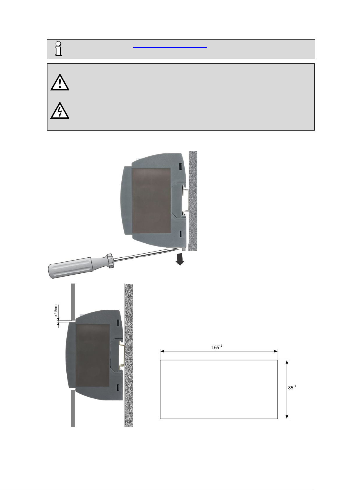
The standard version of the DM5000 can be clipped onto a top-hat rail according to EN60715. Orientation
as shown.
It is the task of this installation to ensure that dangerous connections of the device can not
be touched during operation and that the spread of flames, heat and smoke from the interior
is prevented. This may be done by providing an enclosure (e.g. case, cabinet) or using a
room accessible to qualified personal only and compliant with local fire safety standards.
The device can also be mounted that the front of the
device protrudes through a cut-out in the enclosure. So
the operating buttons and the display become accessible.
With centric mounting using the below maximum cut-out a
gap between enclosure and device results, which does
not exceed 2.5mm on each side.
PM 1001484 000 08 Device handbook SINEAX DM5000 7/96
5. Electrical connections
Ensure under all circumstances that the leads are free of potential
CE conformity mark. The device fulfills the requirements of the applicable EU
CAT III
Measurement category CAT III
when connecting them!
5.1 General safety notes
Please observe that the data on the type plate must be adhered to!
The national provisions have to be observed in the installation and material selection of electric lines,
e.g. in Germany VDE 0100 “Erection of power installations with nominal voltages up to 1000 V“!
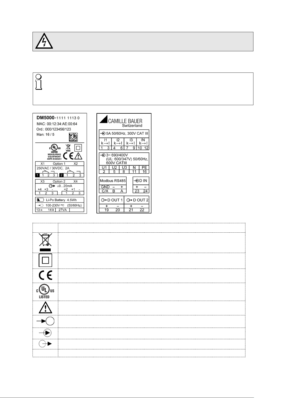
Nameplate of a device with
• TFT display
• Ethernet interface
• Modbus/RTU interface
• Data logger
• 2 relay outputs
• 4 analog outputs
• UPS
Symbol Meaning
Device may only be disposed of in a professional manner!
Double insulation, device of protection class 2
directives.
Products with this mark comply with both the Canadian (CSA) and the American (UL)
requirements.
Caution! General hazard point. Read the operating instructions.
General symbol: Power supply
General symbol: Input
General symbol: Output
PM 1001484 000 08 Device handbook SINEAX DM5000 8/96
5.2 Terminal assignments of the I/O extensions
Function Option 1 Option 2
2 relay outputs
2 analog outputs
4 analog outputs
4 digital inputs (active)
4 digital inputs (passive)
2 temperature inputs
1.1: X1.1 / X1.2 / X1.3
1.2: X2.1 / X2.2 / X2.3
1.1: X2.2(+) / X2. 3(-)
1.2: X2.1(+) / X2. 3(-)
1.1: X2.2(+) / X2.3(-)
1.2: X2.1(+) / X2.3(-)
1.3: X1.2(+) / X1.3(-)
1.4: X1.1(+) / X1.3(-)
1.1: X1.1(-) / X1.3(+)
1.2: X1.2(-) / X1.3(+)
1.3: X2.1(-) / X2.3(+)
1.4: X2.2(-) / X2.3(+)
1.1: X1.1(+) / X1.3(-)
1.2: X1.2(+) / X1.3(-)
1.3: X2.1(+) / X2.3(-)
1.4: X2.2(+) / X2.3(-)
1.1: X1.2 / X1.3
1.2: X2.2 / X2.3
2.1: X3.1 / X3.2 / X3.3
2.2: X4.1 / X4.2 / X4.3
2.1: X4.2(+) / X4.3 (-)
2.2: X4.1(+) / X4.3 (-)
2.1: X4.2(+) / X4.3(-)
2.2: X4.1(+) / X4.3(-)
2.3: X3.2(+) / X3.3(-)
2.4: X3.1(+) / X3.3(-)
2.1: X3.1(-) / X3.3(+)
2.2: X3.2(-) / X3.3(+)
2.3: X4.1(-) / X4.3(+)
2.4: X4.2(-) / X4.3(+)
2.1: X3.1(+) / X3.3(-)
2.2: X3.2(+) / X3.3(-)
2.3: X4.1(+) / X4.3(-)
2.4: X4.2(+) / X4.3(-)
2.1: X3.2 / X3.3
2.2: X4.2 / X4.3
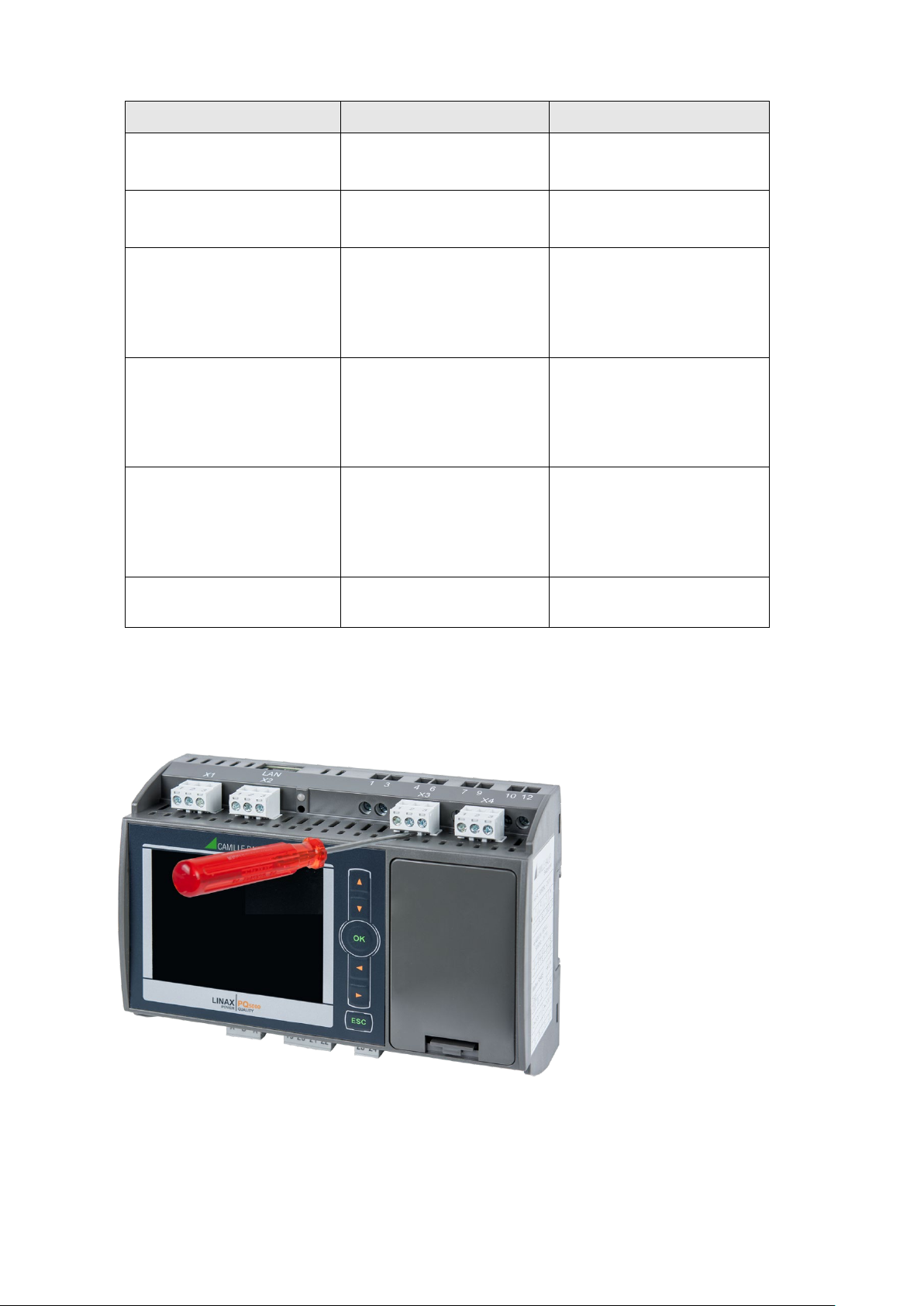
5.3 Current input connections
You may have to remove first the plug-in terminals to get access to the screw terminals of the current
inputs.
PM 1001484 000 08 Device handbook SINEAX DM5000 9/96

5.4 Possible cross sections and tightening torques
Inputs L1(2), L2(5), L3(8), N(11), PE(16), I1(1-3), I2(4-6), I3(7-9), IN(10-12), power supply (13-14)
2
or 2 x 0,5...2.5mm2
2
or 2 x 0,5...2.5mm2
Single wire
Multiwire with end splices
• 1 x 0,5...6.0mm
• 1 x 20 AWG…9 AWG or 2 x 20 AWG…14 AWG
• 1 x 0,5...4.0mm
• 1 x 20 AWG…11 AWG or 2 x 20 AWG…14 AWG
Tightening torque
I/O's, relays, RS485 connector (A, B, C/X)
Single wire
Multiwire with end splices
Tightening torque
5.5 Inputs
All voltage measurement inputs must originate at circuit breakers or fuses rated 5 Amps or
less. This does not apply to the neutral connector. You have to provide a method for
manually removing power from the device, such as a clearly labeled circuit breaker or a
fused disconnect switch in accordance with IEC 60947-2 or IEC 60947-3.
When using voltage transformers you have to ensure that their secondary connections
never will be short-circuited.
• 0.5…0.6Nm
• 4.42…5.31 lbf in
• 1 x 0.5 ... 2.5mm
2
or 2 x 0.5 ... 1.0mm2
• 1 x 20 AWG…14 AWG or 2 x 20 AWG…17 AWG
• 1 x 0.5 ... 2.5mm
2
or 2 x 0.5 ... 1.5mm2
• 1 x 20 AWG…14 AWG or 2 x 20 AWG…16 AWG
• 0.5…0.6Nm
• 4.42…5.31 lbf in
No fuse may be connected upstream of the current measurement inputs!
When using current transformers their secondary connectors must be short-circuited
during installation and before removing the device. Never open the secondary circuit under
load.
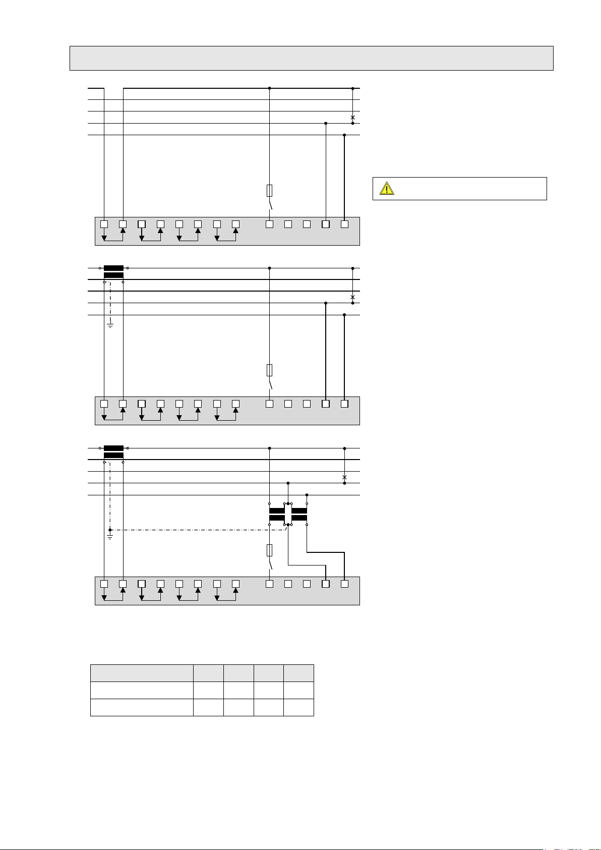
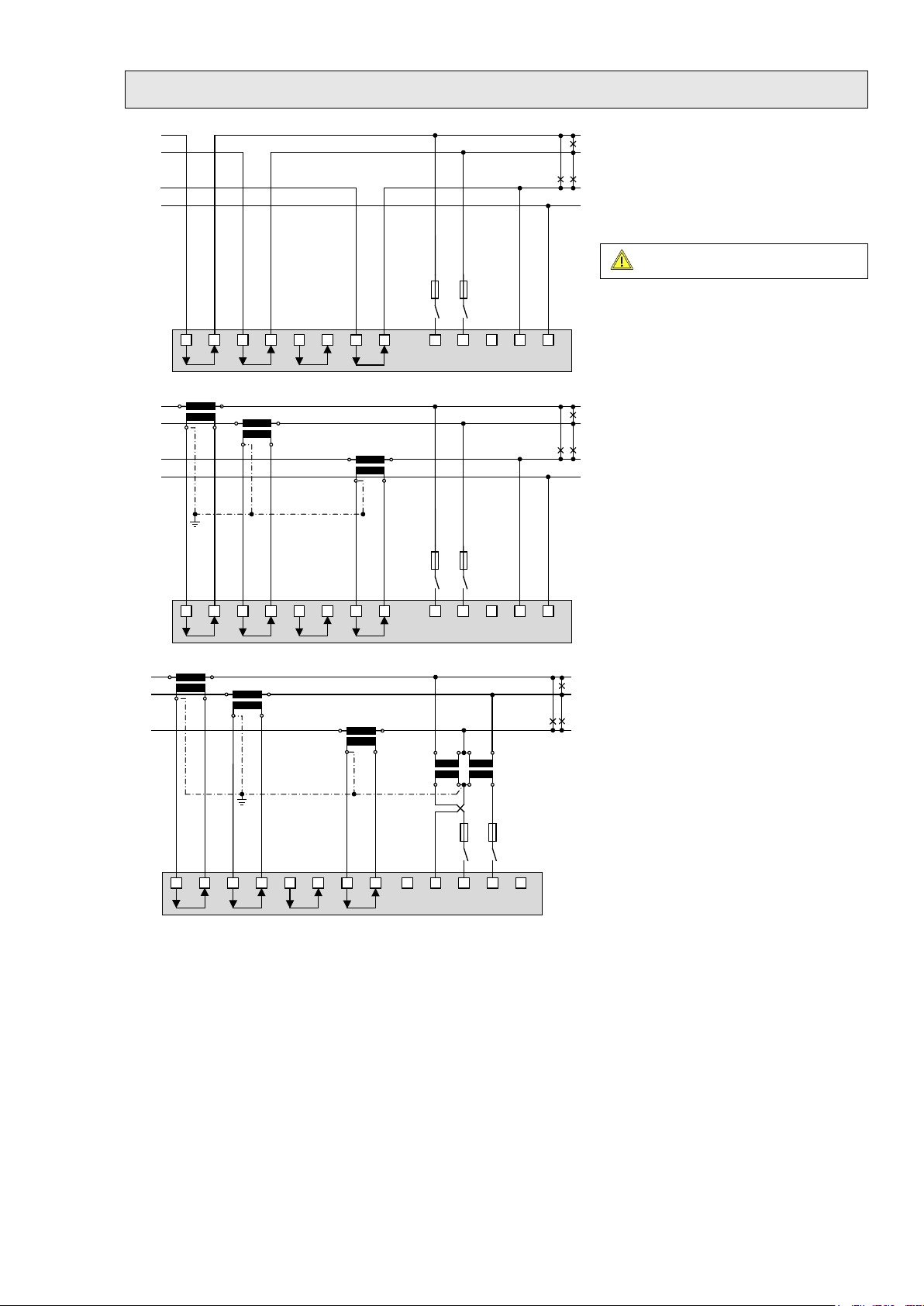
The connection of the inputs depends on the configured system (connection type).
When measuring in systems with neutral wire the connection of the inputs for the
neutral current measurement and the earth connector for determining the zero
displacement voltage is optional.
PM 1001484 000 08 Device handbook SINEAX DM5000 10/96
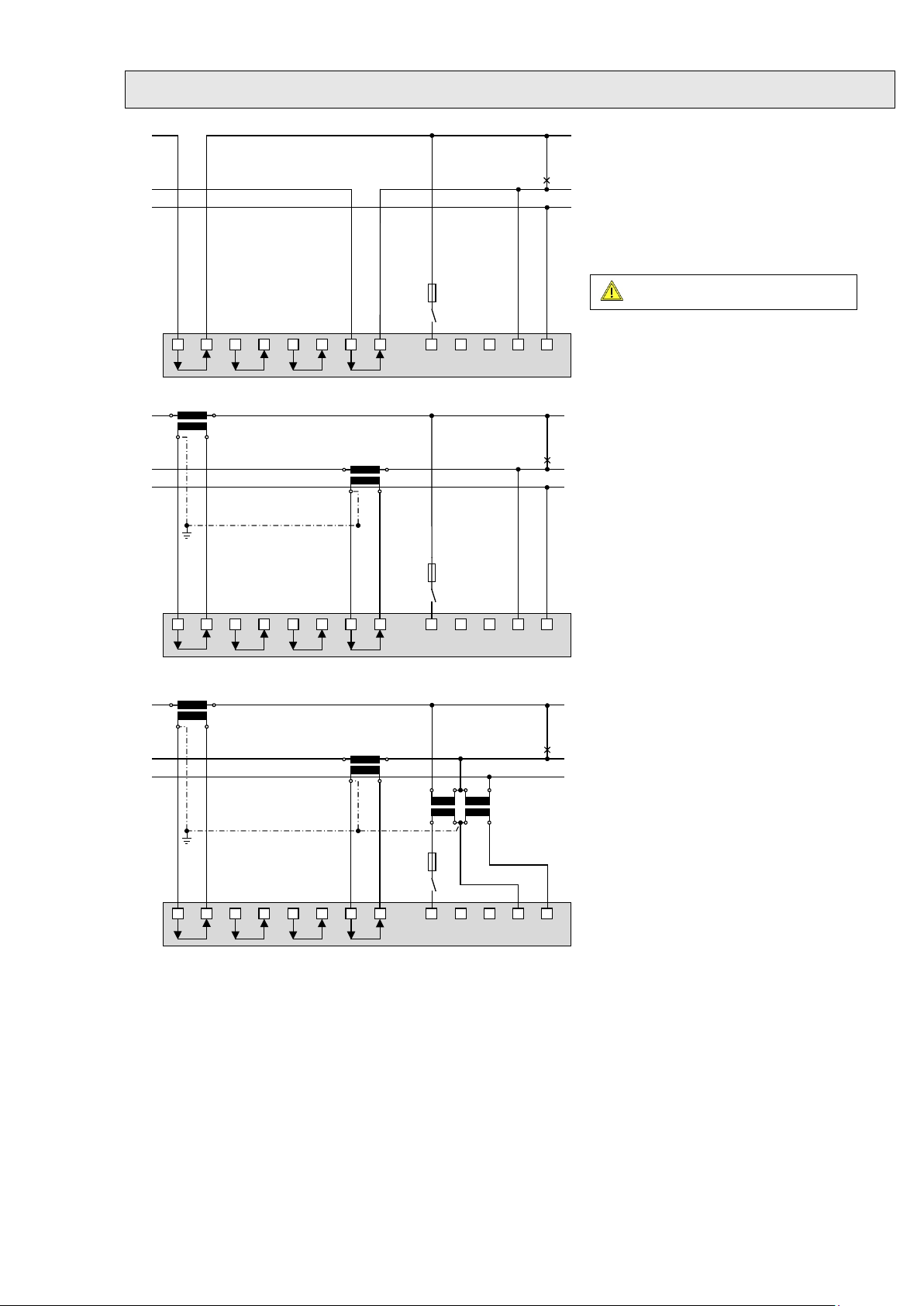
Single-phase AC mains
Maximum permissible rated voltage
L1
L
2 L
3 N
I1
31
I2
4
I3
97
IN
PE
6
10 12
16
112 5 8
L1
N
PE
5 A
(UL listed)
L1 L
2 L3
N
I1
31
I2
4
I3
97
IN
PE
6
10 12
16112
5 8
L
1
N
K
k
L
l
5 A
(UL listed)
K
k
L
l
PE
L1 L2 L3 N
I1
31
I2
4
I3
97
IN
PE
6
10 12
16112 5 8
L1
N
K
k
L
l
5 A
(UL listed)
K
k
L
l
PE
uUvVuUv
V
Direct connection
If current I
or voltage UNE does not need to be
N
measured, connection of IN or PE can be omitted.
300V to ground!
With current transformer
If current IN does not need to be measured, the
corresponding transformer can be omitted.
If voltage U
connection of PE can be omitted.
does not need to be measured,
NE
PM 1001484 000 08 Device handbook SINEAX DM5000 11/96
With current and voltage transformer
If current IN or voltage UNE does not need to be
measured, the corresponding transformers can be
omitted.
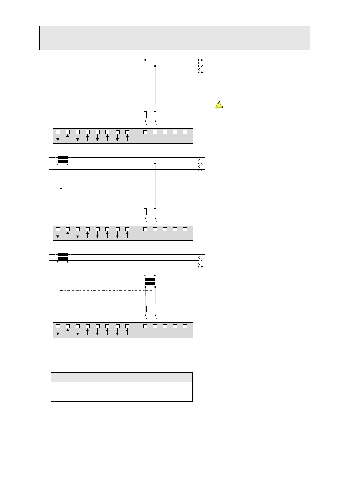
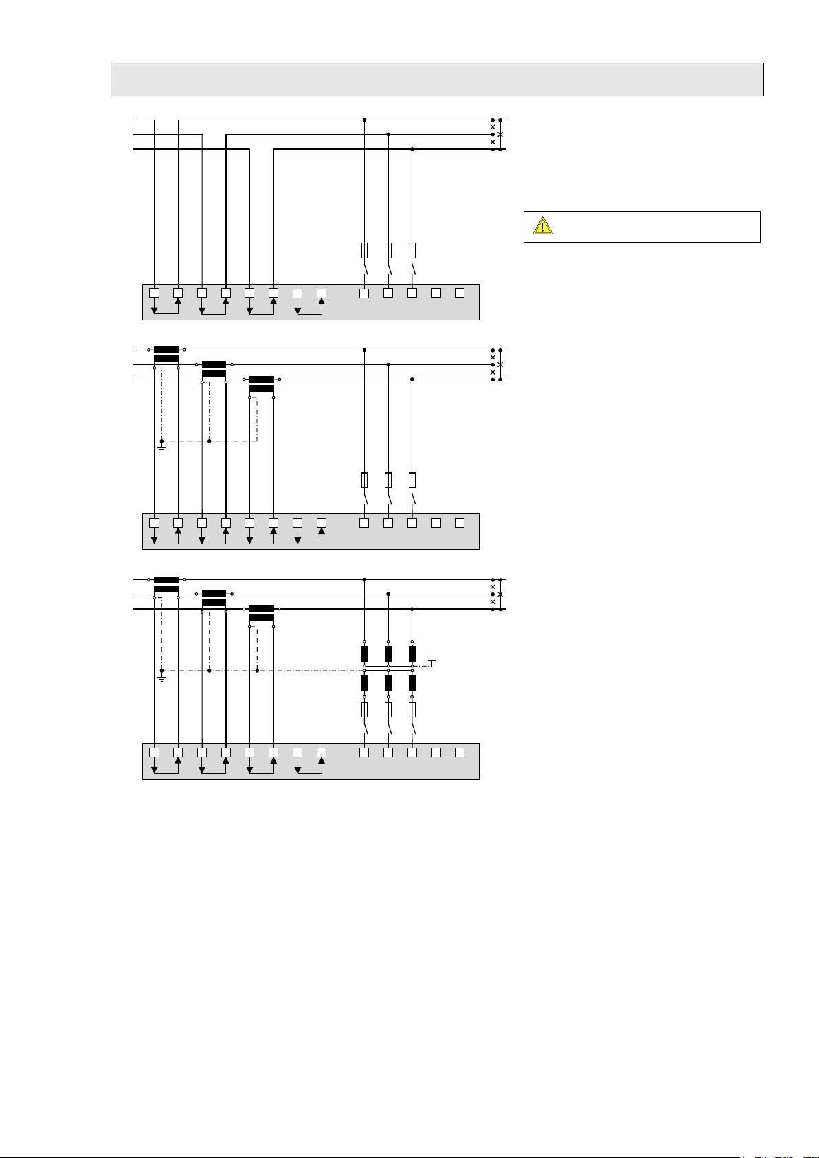
Three wire system, balanced load, phase shift
Maximum permissible rated voltage
L1
L2
L3
L1 L2 L3 N
I1
31
I2
4
I3
97
IN
PE
6
10 12
16
112 5 8
5 A
(
UL listed
)
L1
L2
L3
K
k
L
l
L1 L2 L3 N
I1
31
I2
4
I3
97
IN
PE
6
10 12
16112 5 8
5 A
(UL listed)
L1
L2
L3
K
k
L
l
L1 L2 L3 N
I1
31
I2
4
I3
97
IN
PE
6
10 12
16112 5 8
5 A
(UL listed)
u
U
v
V
current measurement: L1, voltage measurement: L1-L2
Direct connection
300V to ground (520V ph-ph)!
With current transformer
With current and voltage transformers
In case of current measurement via L2 or L3 connect the device
according to the following table:
Terminals 1 3 2 5 8
Current meas. via L2 I2(k) I2(l) L2 L3 -
Current meas. via L3 I3(k) I3(l) L3 L1 -
PM 1001484 000 08 Device handbook SINEAX DM5000 12/96
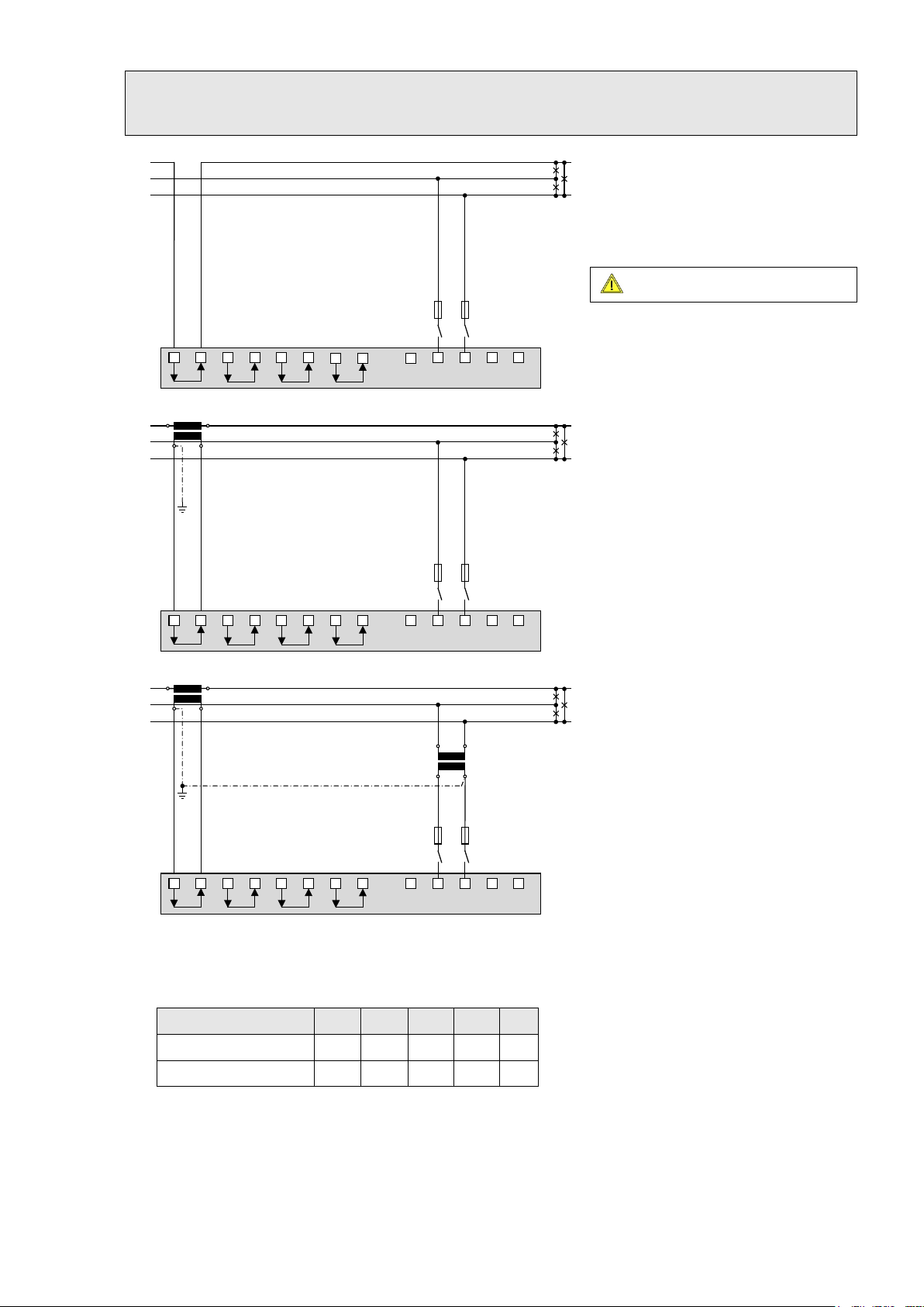
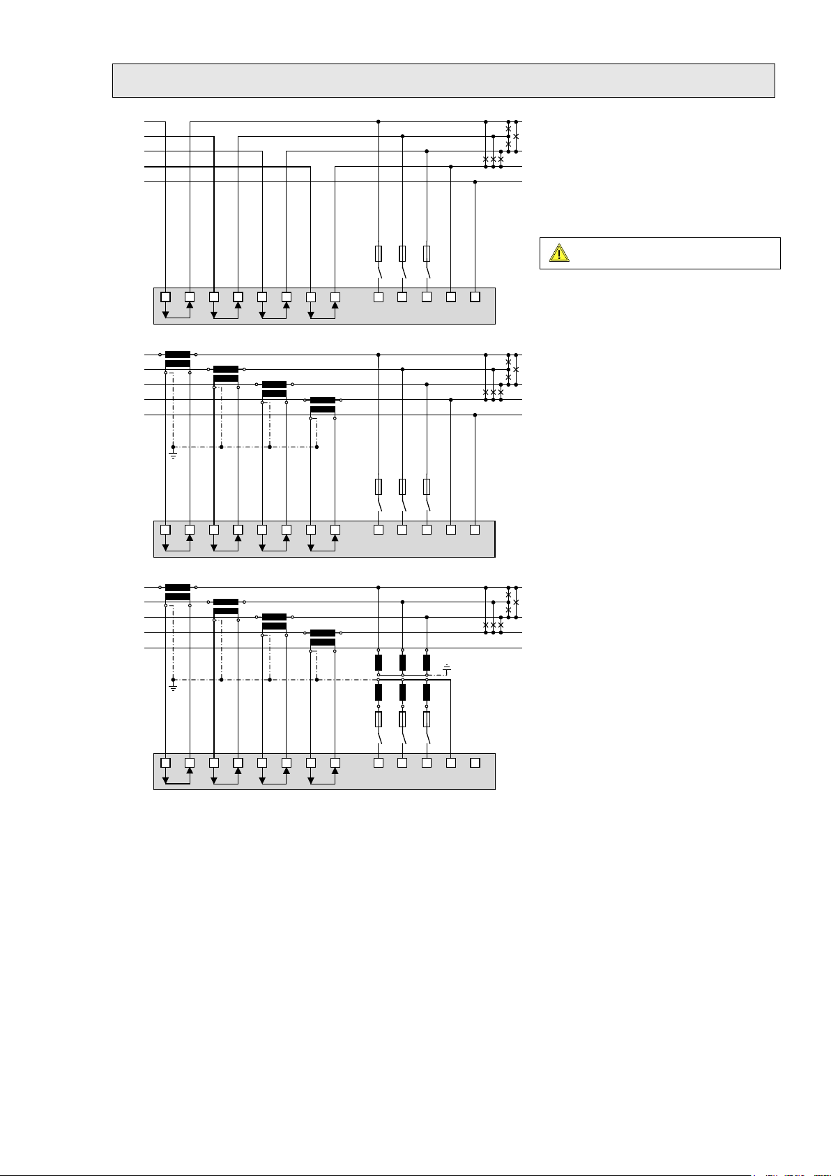
Three wire system, balanced load, phase shift
Maximum permissible rated voltage
L1
L2
L3
L1 L2 L3 N
I1
31
I2
4
I3
97
IN
PE
6
10 12
16
112 5 8
5 A
(
UL listed
)
L1
L2
L3
K
k
L
l
L1 L2 L3 N
I1
31
I2
4
I3
97
IN
PE
6
10 12
16
112 5
8
5 A
(UL listed)
L1
L2
L3
K
k
L
l
L1 L2 L3 N
I1
31
I2
4
I3
97
IN
PE
6
10 12
16112
5 8
5 A
(UL listed)
u
U
v
V
current measurement: L1, voltage measurement: L2-L3
Direct connection
300V to ground (520V ph-ph)!
With current transformer
With current and voltage transformers
In case of current measurement via L2 or L3 connect the device
according to the following table:
Terminals 1 3 2 5 8
Current meas. via L2 I2(k) I2(l) - L3 L1
Current meas. via L3 I3(k) I3(l) - L1 L2
PM 1001484 000 08 Device handbook SINEAX DM5000 13/96

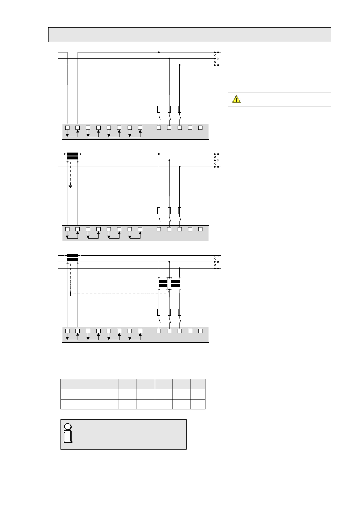
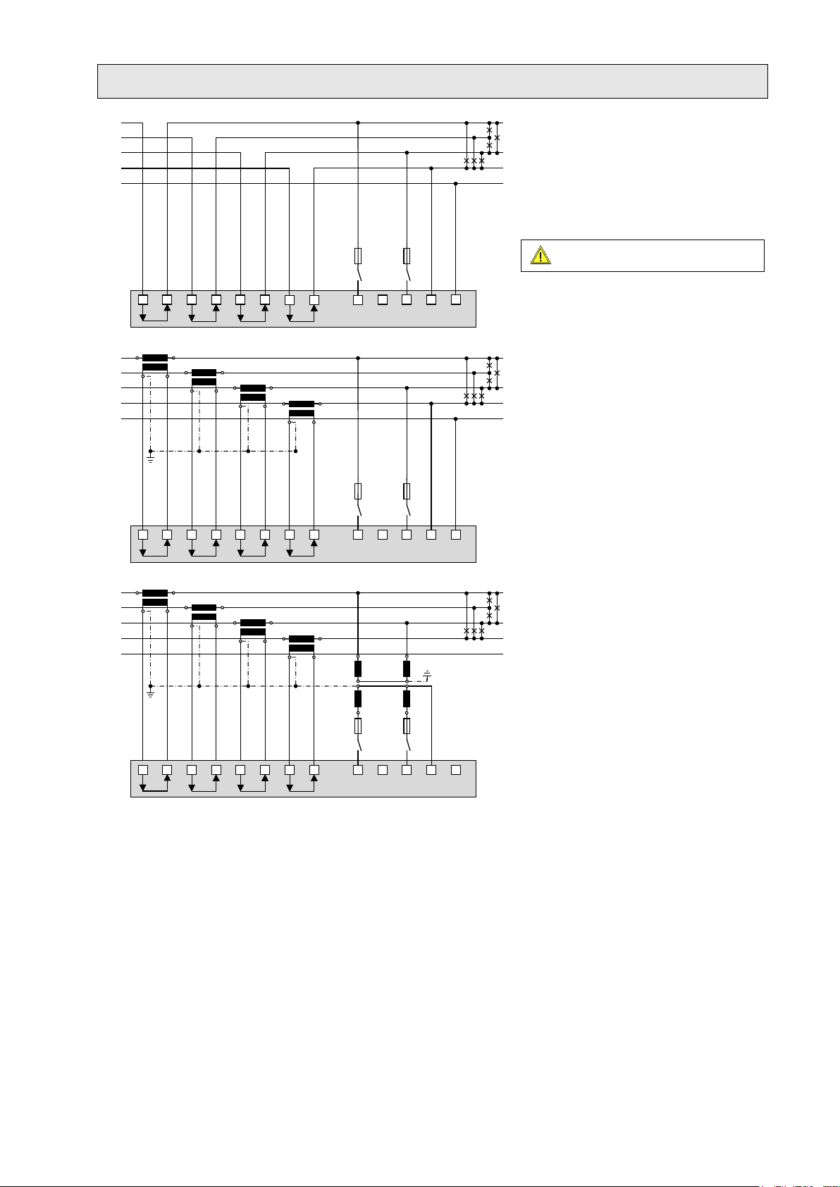
Three wire system, balanced load, phase shift
Maximum permissible rated voltage
L1
L2
L3
L1 L2 L3 N
I1
31
I2
4
I3
97
IN
PE
6
10 12
16
112 5 8
5 A
(
UL listed
)
L1
L2
L3
K
k
L
l
L1 L2 L3 N
I1
31
I2
4
I3
97
IN
PE
6
10 12
16112 5 8
5 A
(UL listed)
L1
L2
L3
K
k
L
l
L1 L2 L3 N
I1
31
I2
4
I3
97
IN
PE
6
10 12
16112 5 8
5 A
(UL listed)
u
U
v
V
current measurement: L1, voltage measurement: L3-L1
Direct connection
300V to ground (520V ph-ph)!
With current transformer
With current and voltage transformers
In case of current measurement via L2 or L3 connect the device
according to the following table:
Terminals 1 3 2 5 8
Current meas. via L2
Current meas. via L3
I2(k)
I2(l)
I3(k) I3(l) L3 - L2
L2 - L1
PM 1001484 000 08 Device handbook SINEAX DM5000 14/96
Three wire system, balanced load, current measurement via L1
Maximum permissible rated voltage
L
1
L2
L3
L1 L2 L3 N
I1
31
I2
4
I3
97
IN
PE
6
10 12
16
112 5 8
5 A
(UL listed)
L1
L2
L3
K
k
L
l
L1 L
2 L3
N
I1
3
1
I2
4
I3
97
IN
PE
6
10
12
16112
5 8
5 A
(UL listed)
L
1
L2
L3
K
k
L
l
L1 L2 L3 N
I1
31
I2
4
I3
97
IN
PE
6
10 12
16112
5 8
5 A
(UL listed
)
u
U
v
V
u
U
v
V
Direct connection
300V to ground (520V ph-ph)!
With current transformer
With current and voltage transformers
In case of current measurement via L2 or L3 connect the device
according to the following table:
Terminals 1 3 2 5 8
Current meas. via L2
Current meas. via L3
By rotating the voltage connections the
measurements U12, U23 and U31 will be
assigned interchanged!
I2(k)
I2(l)
I3(k) I3(l) L3 L1 L2
L2 L3 L1
PM 1001484 000 08 Device handbook SINEAX DM5000 15/96
Four wire system, balanced load, current measurement via L1
Maximum permissible rated voltage
L1
L
2 L
3 N
I1
3
1
I2
4
I3
97
IN
PE
6
10 12
16
112 5 8
L1
L2
L3
N
PE
5 A
(UL listed)
L1 L2 L3 N
I1
31
I2
4
I3
97
IN
PE
6
10 12
16112 5 8
L1
L2
L3
N
K
k
L
l
PE
5 A
(UL listed)
L1 L2 L3 N
I1
31
I2
4
I3
97
IN
PE
6
10 12
16112 5 8
L1
L2
L3
N
K
k
L
l
PE
u
U
v
V
u
U
v
V
5 A
(UL listed)
Direct connection
If voltage U
does not need to be measured,
NE
connection of PE can be omitted.
300V to ground!
With current transformer
If voltage UNE does not need to be measured,
connection of PE can be omitted.
In case of current measurement via L2 or L3 connect the device
according to the following table:
Terminals 1 3 2 11
Current meas. via L2
Current meas. via L3
PM 1001484 000 08 Device handbook SINEAX DM5000 16/96
With current and voltage transformer
If voltage UNE does not need to be measured, the
corresponding transformer can be omitted.
I2(k)
I2(l)
I3(k) I3(l) L3 N
L2 N
Three wire system, unbalanced load
Maximum permissible rated voltage
L
1
L2 L3 N
I1
31
I2
4
I3
97
IN
PE
6
10 12
16
112 5 8
L1
L2
L3
5 A
(UL listed)
L
1 L2 L
3 N
I1
3
1
I
2
4
I
3
97
IN
PE
6
10
12
1611
2 5 8
L1
L2
L3
K
k
L
l
K
k
L
l
K
k
L
l
5
A
(UL listed)
L1 L2 L3 N
I1
31
I2
4
I3
97
IN
PE
6
10 12
16112 5 8
L1
L
2
L3
K
k
L
l
K
k
L
l
K
k
L
l
x
u
X
U
X
U
X
U
x
u
x
u
5 A
(UL listed)
Direct connection
300V to ground (520V ph-ph)!
With current transformers
With current and 3 single-pole isolated
voltage transformers
PM 1001484 000 08 Device handbook SINEAX DM5000 17/96

Three wire system, unbalanced load, Aron connection
Maximum permissible rated voltage
L
1
L2 L3 N
I1
31
I2
4
I3
97
IN
PE
6
10 12
16
112 5 8
L1
L2
L3
5 A
(UL listed)
L1 L2 L3 N
I1
31
I2
4
I3
97
IN
PE
6
10 12
16112 5 8
L1
L2
L3
K
k
L
l
K
k
L
l
5 A
(UL listed)
L1 L2 L3 N
I1
31
I2
4
I3
97
IN
PE
6
10 12
16112 5 8
L1
L2
L3
K
k
L
l
K
k
L
l
x
u
X
U
X
U
X
U
x
u
x
u
5 A
(UL listed)
Direct connection
300V to ground (520V ph-ph)!
With current transformers
With current and 3 single-pole isolated
voltage transformers
PM 1001484 000 08 Device handbook SINEAX DM5000 18/96
Four wire system, unbalanced load
Maximum permissible rated voltage
L1 L2 L3 N
I1
31
I2
4
I3
97
IN
PE
6
10 12
16
112 5 8
L1
L2
L3
N
5 A
(UL listed)
PE
L1
L2 L3 N
I1
31
I2
4
I3
97
IN
PE
6
10 12
16112 5 8
L1
L2
L3
N
K
k
L
l
K
k
L
l
K
k
L
l
5 A
(UL listed)
K
k
L
l
PE
L1 L2 L3 N
I1
31
I2
4
I3
97
IN
PE
6
10 12
16112 5 8
L1
L2
L3
N
K
k
L
l
K
k
L
l
K
k
L
l
x
u
X
U
XUX
U
x
u
x
u
5 A
(UL listed)
K
k
L
l
PE
Direct connection
If current I
or voltage UNE does not need to be
N
measured, connection of IN or PE can be omitted.
300V to ground (520V ph-ph)!
With current transformer
If voltage UNE does not need to be measured,
connection of PE can be omitted.
If current I
corresponding transformer can be omitted.
does not need to be measured, the
N
With current and voltage transformer
If current IN does not need to be measured, the
corresponding transformer can be omitted.
PM 1001484 000 08 Device handbook SINEAX DM5000 19/96
Four wire system, unbalanced load, Open-Y
Maximum permissible rated voltage
L1 L2 L3 N
I1
31
I2
4
I3
97
IN
PE
6
10 12
16
112 5 8
L1
L2
L3
N
5 A
(UL listed)
PE
L1
L2 L3 N
I1
31
I2
4
I3
97
IN
PE
6
10 12
16112 5 8
L1
L2
L3
N
K
k
L
l
K
k
L
l
K
k
L
l
5 A
(UL listed
)
K
k
L
l
PE
L1 L2 L3 N
I1
31
I2
4
I3
97
IN
PE
6
10 12
16112 5 8
L1
L2
L3
K
k
L
l
K
k
L
l
K
k
L
l
x
u
X
U
X
U
x
u
5 A
(UL listed)
L1 L2 L3 N
I1
31
I2
4
I3
97
IN
PE
6
10 12
16112 5 8
N
PE
K
k
L
l
Direct connection
If current I
or voltage UNE does not need to be
N
measured, connection of IN or PE can be omitted.
300V to ground (520V ph-ph)!
With current transformer
If voltage UNE does not need to be measured,
connection of PE can be omitted.
If current I
corresponding transformer can be omitted.
does not need to be measured, the
N
With current and voltage transformer
If current IN does not need to be measured, the
corresponding transformer can be omitted.
PM 1001484 000 08 Device handbook SINEAX DM5000 20/96
Split-phase ("two phase system"), unbalanced load
Maximum permissible rated voltage
L1 L2 L3 N
I1
31
I2
4
I3
97
IN
PE
6
10 12
16
112 5 8
L1
L2
N
5 A
(UL listed)
PE
L1 L2 L3 N
I1
31
I2
4
I3
97
IN
PE
6
10 12
16112 5 8
L1
L2
N
K
k
L
l
K
k
L
l
5 A
(UL listed)
K
k
L
l
PE
L1 L2 L3
N
I1
31
I2
4
I3
97
IN
PE
6
10 12 16
11 2 5 8
L1
L2
N
K
k
L
l
K
k
L
l
5 A
(UL listed)
K
k
L
l
u
U
v
V
u
U
v
V
Direct connection
300V to ground (600V ph-ph)!
With current transformers
With current and voltage transformer
In systems without a primary neutral conductor a
voltage transformer with a secondary center tap
can also be used.
PM 1001484 000 08 Device handbook SINEAX DM5000 21/96
5.6 Power supply
A marked and easily accessible current limiting switch in accordance with IEC 60947-2 has
to be arranged in the vicinity of the device for turning off the power supply. Fusing should be
10 Amps or less and must be rated for the available voltage and fault current.
5.7 Relays
When the device is switched off the relay contacts are de-energized, but dangerous
voltages may be present.
Relays are available for device versions with corresponding I/O extensions only.
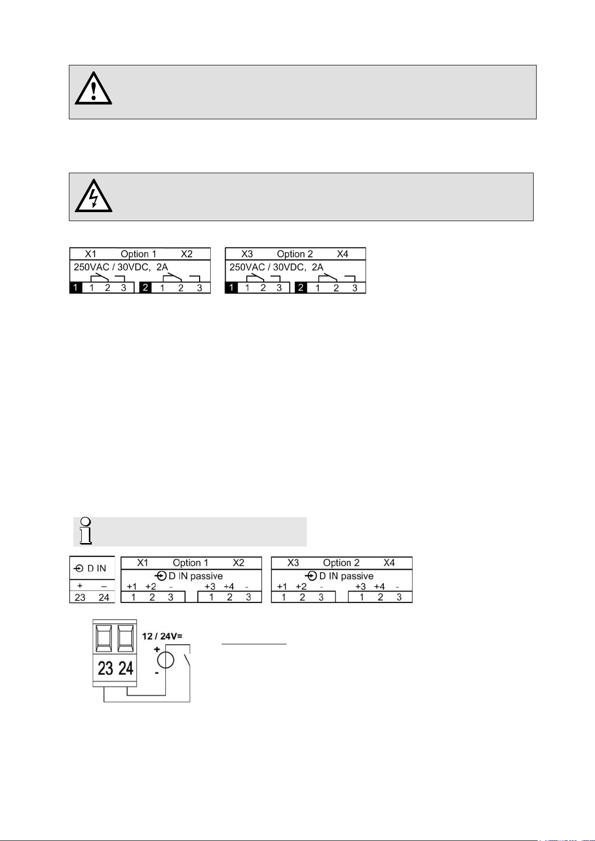
5.8 Digital inputs
The device provides a standard passive digital input. In addition, depending on the device version, there
may be 4-channel passive or active digital input modules available.
Usage of the standard digital input
► Status input
► Meter tariff switching
Usage of the inputs of the optional input modules
► Counting input for pulses of meters for any kind of energy (pulse width 70…250ms)
► Operating feedback of loads for operating time counters
► Trigger and release signal for monitoring functions
Passive inputs (external power supply with 12 / 24 VDC required)
The power supply shall not exceed 30V DC!
Technical data
Input current < 7,0 mA
Logical ZERO - 3 up to + 5 V
Logical ONE 8 up to 30 V
PM 1001484 000 08 Device handbook SINEAX DM5000 22/96
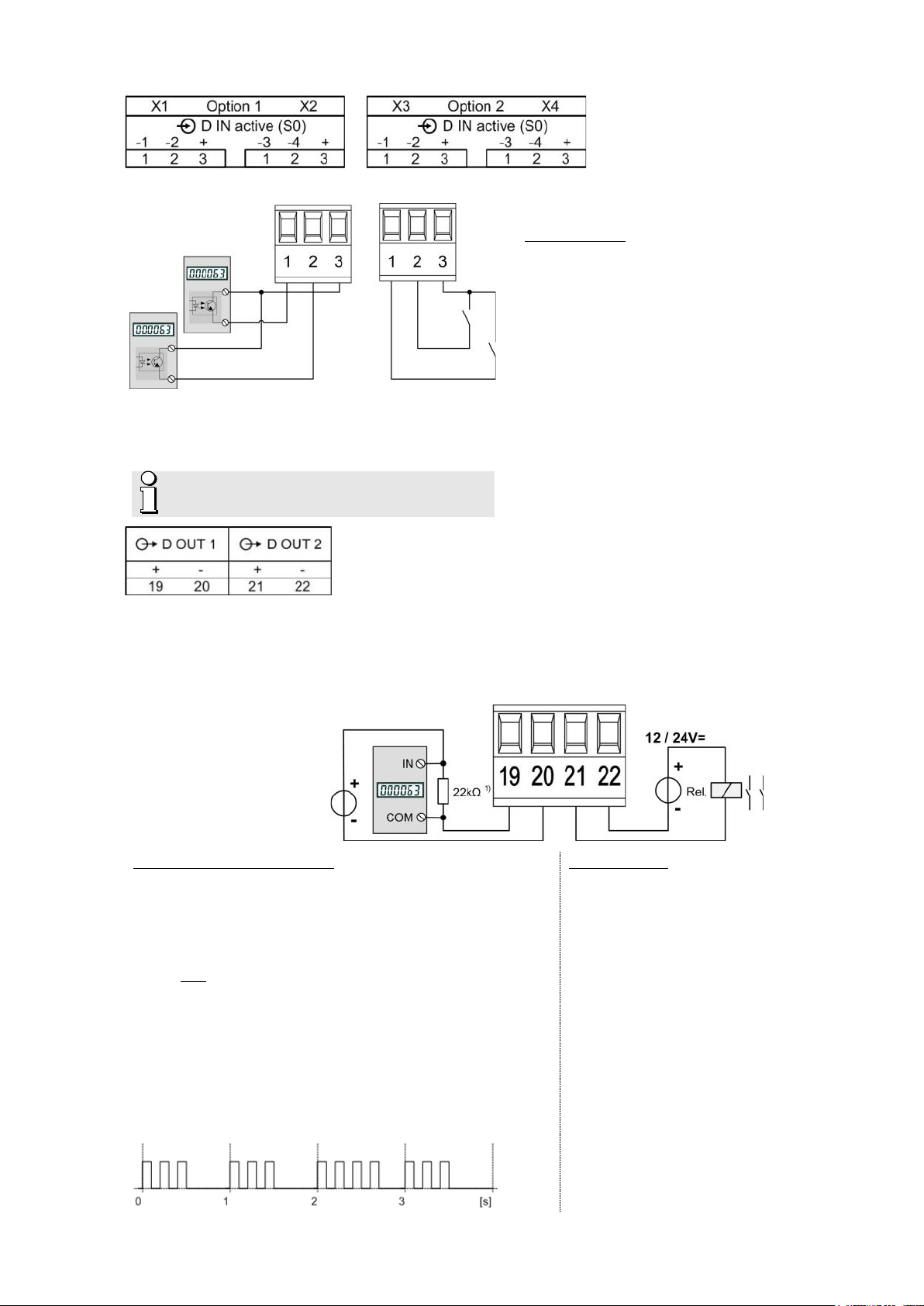
Active inputs (no external power supply required)
Driving a counter mechanism
Driving a relay
Example with meter pulse and status inputs
Technical data
acc. EN62053-31, class B
Open circuit voltage ≤ 15 V
Short circuit current < 15 mA
Current at R
=800Ω ≥ 2 mA
ON
5.9 Digital outputs
The device has two standard digital outputs for which an external 12 / 24 VDC power supply is required.
The power supply shall not exceed 30V DC!
Usage as digital output
► Alarm output
► State reporting
► Pulse output to an external counter (acc. EN62053-31)
► Remote controlled output
1) Recommended if input
impedance of counter
> 100 kΩ
The width of the energy pulses can be selected within a
range of 30 up to 250ms, but have to be adapted to the
external counter mechanism.
Electro mechanical meters typically need a pulse width
of 50...100ms.
Electronic meters are partly capable to detect pulses in
the kHz range. There are two types: NPN (active negative
edge) and PNP (active positive edge). For this device a
PNP is required. The pulse width has to be ≥ 30ms (acc.
EN62053-31). The delay between two pulses has to be at
least the pulse width. The smaller the pulse width, the
higher the sensitivity to disturbances.
PM 1001484 000 08 Device handbook SINEAX DM5000 23/96
Rated current 50 mA (60 mA max.)
Switching frequency (S0) ≤ 20 Hz
Leakage current 0,01 mA
Voltage drop < 3 V
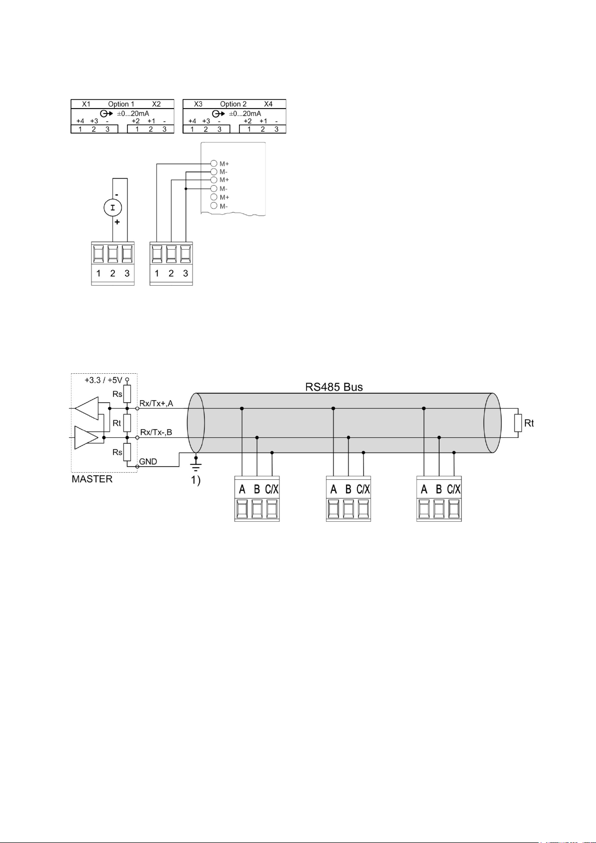
5.10 Analog outputs
Analog outputs are available for devices with corresponding I/O extensions only. See nameplate. Analog
outputs may be remote controlled.
Connection to an analog input card of a PLC or a
control system
The device is an isolated measurement device. The
module outputs are galvanically connected, but the
modules isolated from each other. To reduce the
influence of disturbances shielded a twisted-pair cables
should be used. The shield should be connected to earth
on both opposite ends. If there are potential differences
between the ends of the cable the shield should be
earthed on one side only to prevent from equalizing
currents.
Under all circumstances consider as well appropriate
remarks in the instruction manual of the system to
connect.
5.11 Modbus interface RS485
Via the optional Modbus interface measurement data may be provided for a superior system. However,
the Modbus interface cannot be used for device parameterization.
1) One ground connection only.
This is possibly made within the
master (PC).
The signal wires (A, B) have to be twisted. GND (C/X) can be connected via a wire or via the cable shield.
In disturbed environments shielded cables must be used. Supply resistors (Rs) have to be present in bus
master (PC) interface. Stubs should be avoided when connecting the devices. A pure line network is ideal.
You may connect up to 32 Modbus devices to the bus. A proper operation requires that all devices
connected to the bus have equal communication settings (baud rate, transmission format) and unique
Modbus addresses.
The bus system is operated half duplex and may be extended to a maximum length of 1200 m without
repeater.
Rt: Termination resistors: 120 Ω each
for long cables (> approx. 10 m)
Rs: Bus supply resistors,
390 Ω each
PM 1001484 000 08 Device handbook SINEAX DM5000 24/96
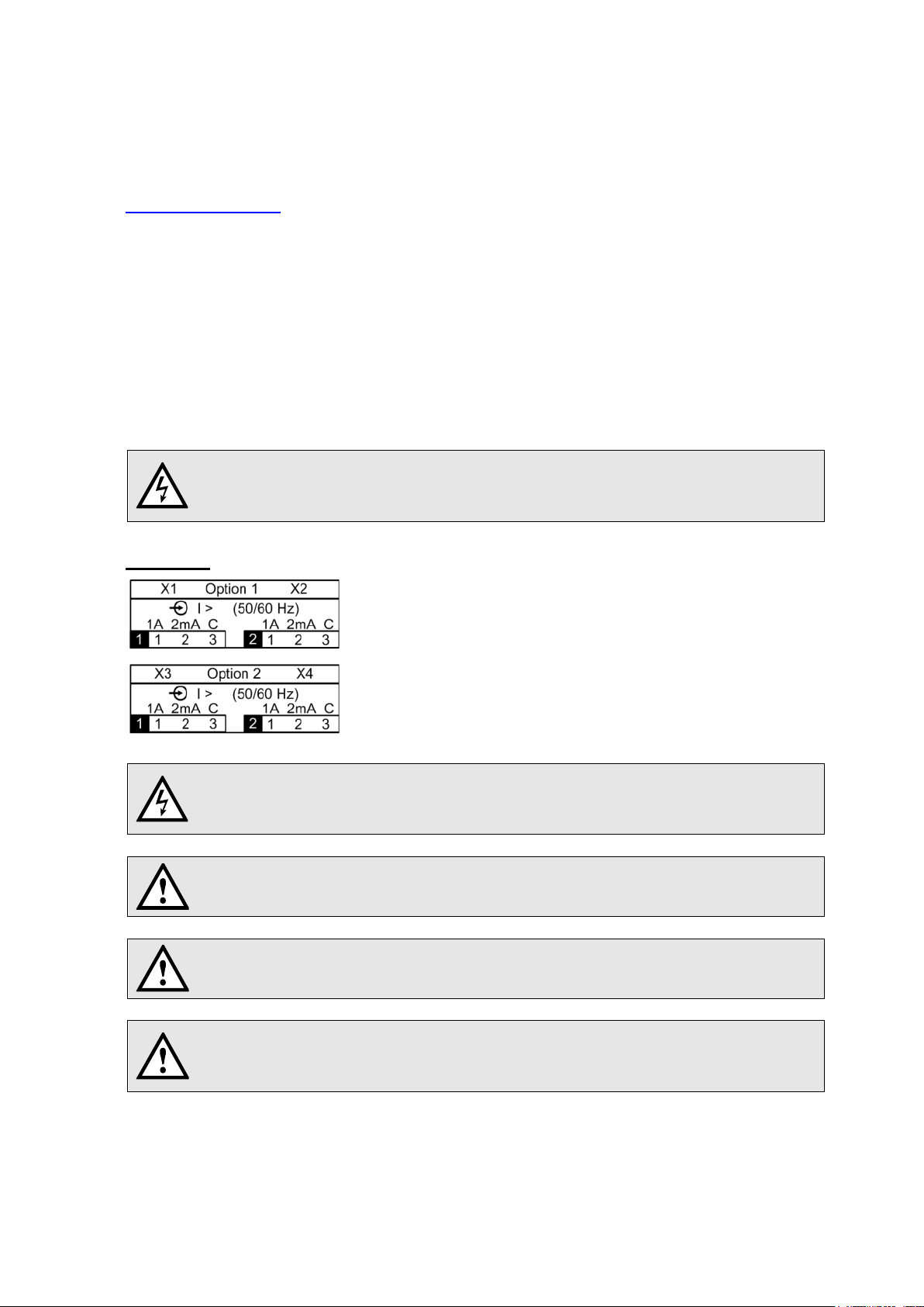
5.12 Fault current detection
Use only transformers intended for this application, according to our current transformer
catalog, or transformers that fulfill the above specification. Using transformers with
divergent specifications may damage the measu
The current transformers including the conductor isolation must guarantee in total a
reinforced or double insulation between the mains circuit connected on the primary side
and the measuring inputs of the device
Only one measurement range may be connected per measuring channel!
The COM connectors of both measurement channels are internally connected.
For 2mA inputs a connection monitoring (breakage) is implemented. An alarm state is
signaled for the respective measurement channels if either the current
disconnected or the connection to the transformer is interrupted.
Each fault current module provides two channels for monitoring differential or fault currents in earthed
AC current systems. In any case, measurement has to be performed via suitable current transformers, a
direct measurement is not possible. The module is not suited for monitoring operating currents of normally
live conductors (L1, L2, L3, N).
Measurement ranges
Each channel provides two measurement ranges:
a) Measurement range 1A
• Application: Direct measurement of a fault or earth wire current
• Meas. transformer: Current transformer 1/1 up to 1000/1A; 0.2 up to 1.5VA;
Instrument security factor FS5
b) Measurement range 2mA
• Application: Residual current monitoring (RCM)
• Meas. transformer: Residual current transformer 500/1 up to 1000/1A
Rated burden 100 Ω / 0.025 VA up to 200 Ω / 0.06 VA
rement inputs.
Connection
.
transformer is
PM 1001484 000 08 Device handbook SINEAX DM5000 25/96

Example: Fault current monitoring in a TNS system
Hints
(1) If the current transformers for the fault current detection needs to be grounded on the secondary
side this has to be done via the COM connector.
(2) Note that all conductors have to pass through the opening of the
residual current transformer in the same direction.
(3) A possible fault current flows through the protective
earth conductor (PE). It can only be detected if the PE
conductor is not routed through the residual current
transformer. If this cannot be avoided, e.g. due to using
a multi-wire cable with all conductors, the PE conductor
must be returned through the transformer.
(4) The cable or individual conductors should be routed through the
transformer as centered as possible in order to minimize
measurement errors.
(5) Neither the current transformers nor the measurement leads should be mounted or installed close to
strong magnetic fields. Measurement lines should also not be laid in parallel to power lines.
(6) For measurement range 1A only: The rated output of the transformer must be chosen that it is
reached when the rated secondary current (1A) flows. Consider that the burden of the transformer is
not only made up by the burden of the measurement input, but also by the resistance of the
measurement lines and the self-consumption of the transformer (copper losses).
A rated output selected too low leads to saturation losses in the transformer. The secondary
rated current can no longer be reached as the transformer reaches its limits before.
A rated output selected too high or an exceeding instrument security factor (>FS5) may cause
damage to the measuring inputs in case of overload.
(7) For the connection of the transformer to the fault detection module use …
2
Conductor cross sections of 1.0 up to 2.5mm
(16-14 AWG)
Pairwise twisted conductors in case of short cable lengths
Shielded cables (shield grounded on one side only) in disturbed environment or in case of long
cable lengths
PM 1001484 000 08 Device handbook SINEAX DM5000 26/96
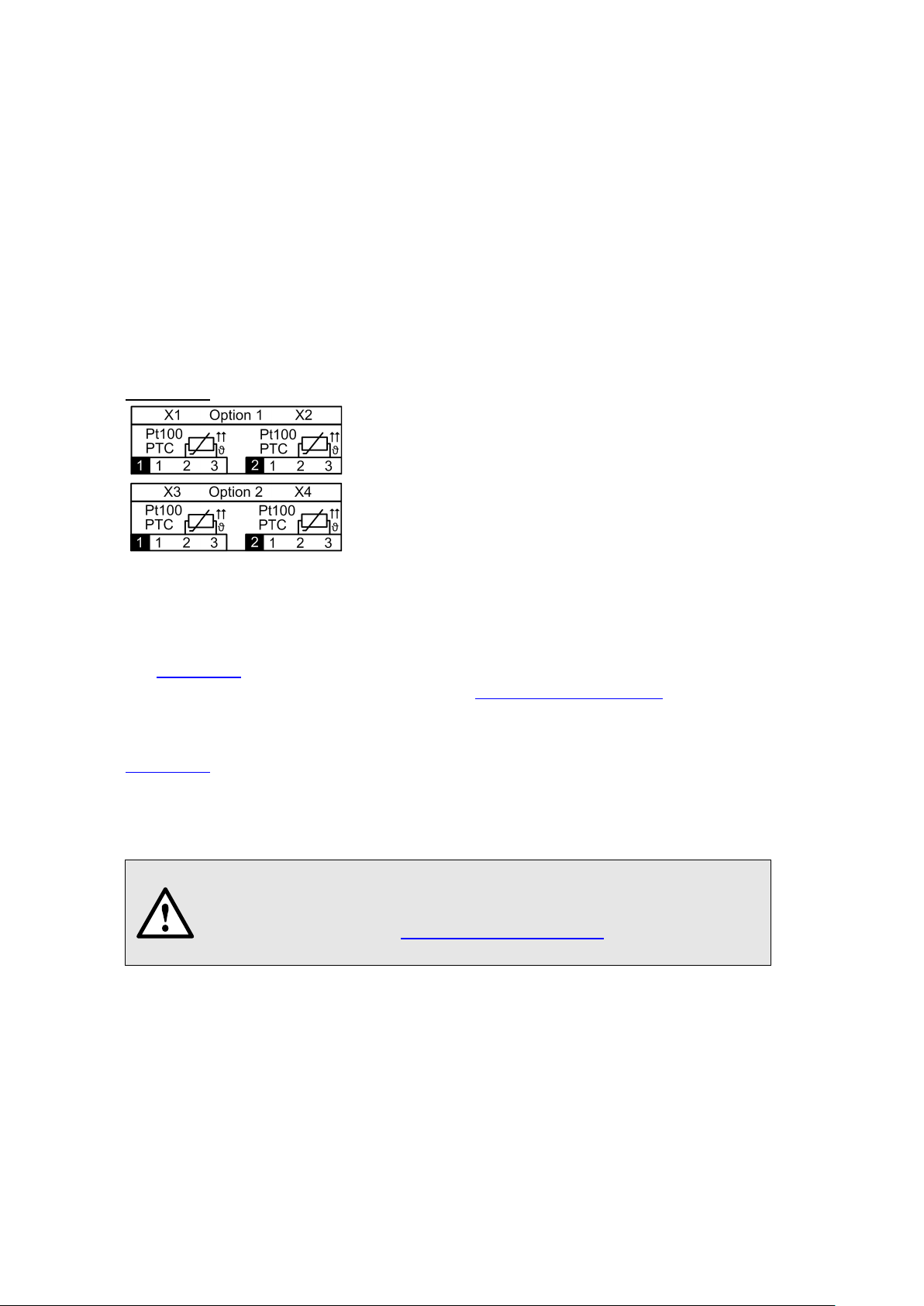
5.13 Temperature inputs
Each temperature module provides two channels for temperature monitoring. They can be used in two
ways:
a) Temperature measurement via Pt100 sensor
• Measurement range: -50 up to 250°C
• 2 configurable alarm limits
• Configurable alarm delay time for ON / OFF
• Short circuit and wire / sensor breakage monitoring
b) Temperature monitoring with PTC sensors
• Monitoring the PTC response temperature
• Short circuit monitoring
• Serial connection of up to 6 single sensors or up to 2 triplet sensors
Connection
5.14 Uninterruptible power supply (UPS)
The battery pack for the uninterruptible power supply is supplied separately. Please note that compared to
the storage temperature range of the base unit the storage temperature range of the battery pack is
restricted.
Ensure that devices with uninterruptible power supply are used in an environment in accordance with the
specification
recharged.
Due to aging the capacity of the battery decreases. To ensure a successful operation of the device during
power interruptions the battery needs to be replaced every 3 up to 5 years.
. Outside this operating temperature range, it is not ensured that the battery pack is
Potential for Fire or Burning. Do not disassemble, crush, heat or burn the
removed battery pack.
Replace battery pack with a battery pack of the same type only. Use of another
battery may present a risk of fire or explosion.
PM 1001484 000 08 Device handbook SINEAX DM5000 27/96
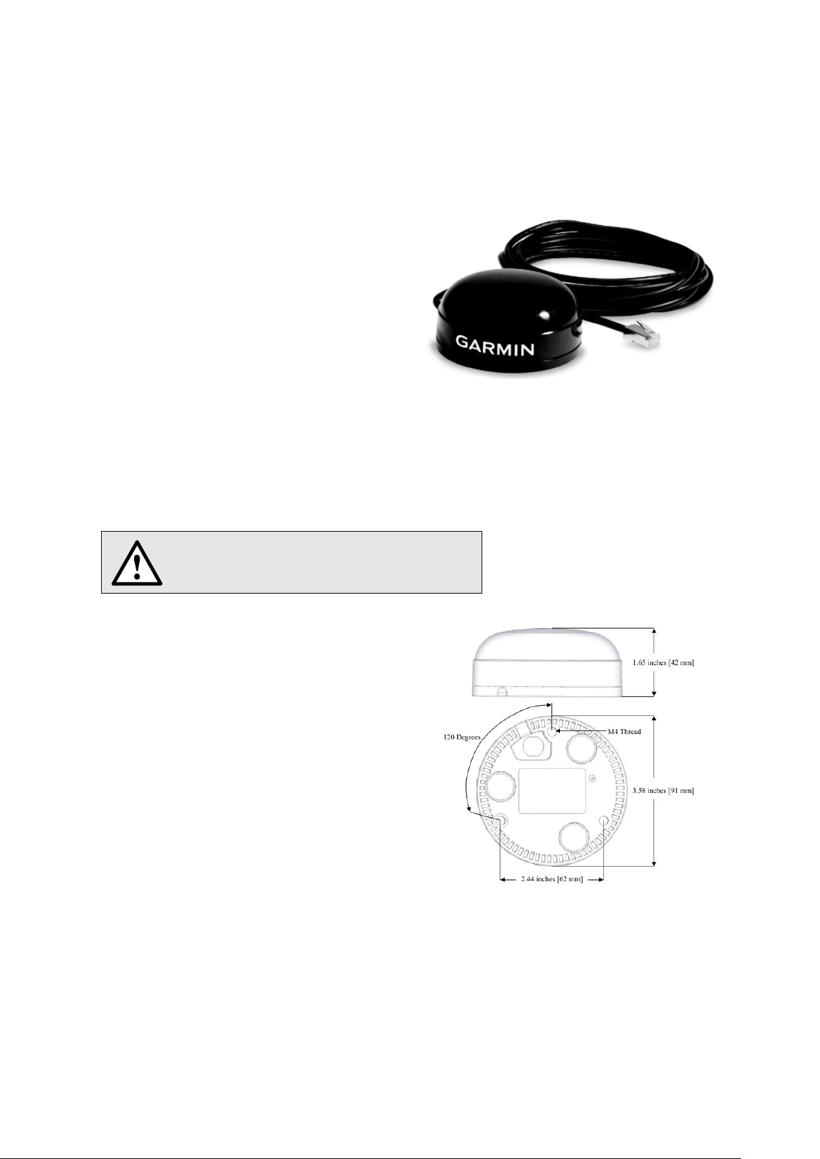
5.15 GPS time synchronization
Only use the receiver Garmin GPS 16x-LVS (article
The optional GPS connection module serves for connecting a GPS receiver as a very accurate time
synchronization source for the measurement device. The GPS receiver, available as an accessory, is
used as outdoor antenna to process data from multiple GPS satellites simultaneously.
GPS receiver
no. 181‘131), offered as an accessory. This device
is preconfigured by us and provides the required
time information (sentences) without further
configuration effort.
• Protection: IPx7 (waterproof)
• Operating temperature: -30…80°C
• Storage temperature: -40…80°C
• 1Hz pulse accuracy: 1μs
• Connector: RJ45
Choosing a mounting location
For a correct operation the GPS receiver requires data from at least 3 satellites at the same time.
Therefore position the receiver so that the clearest possible view of the sky and horizon in all direction is
obtained. This can be on the roof of a building, at best without reception being restricted by other
buildings or obstacles. Avoid mounting the receiver next to large areas of conductible material, as this
may cause poor signal reception. It should be also not closer than 1 meter away from any other antenna.
If lightning protection is required, this must be
provided by the user.
Mounting the GPS receiver
• The GPS receiver Garmin GPS 16x-LVS
can be flush mounted by means of 3 M4
screws.
• 120° distribution over a circle of ø71.6mm
• Thread length max. 8mm. Using longer
screws may damage the GPS receiver.
PM 1001484 000 08 Device handbook SINEAX DM5000 28/96
Connecting the GPS receiver
When connecting a GPS receiver for the first time or when it has been out of
operation for a long time, it may take up to 1 hour for finding enough sa
GPS receiver operation and thus for a reliable time synchronization.
Never connect the RJ45 connector of the connecting cable
directly to a network device such as a router or switch. These
devices could be damaged.
The GPS receiver is plugged directly into the GPS connection module. The connection cable has a length
of 5 m. It may be extended using an RJ45 coupling and an Ethernet cable. The connection cable should
not be laid in parallel to live conductors. Twisting or sharp kinking of the cable should be avoided.
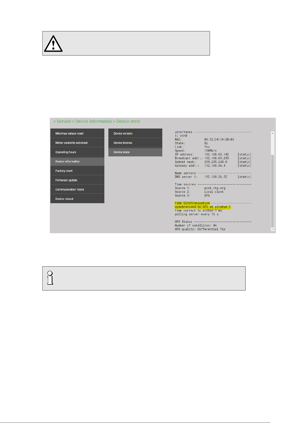
Commissioning
• In the settings menu change time synchronization to „NTP server / GPS“
• Check the time synchronization status
• The time synchronization can be restarted by switching the time synchronization off and on again.
• Time synchronization via GPS and NTP server may work in parallel. If both synchronization sources
are available, the system uses the more accurate time source, which is normally GPS.
tellites for
PM 1001484 000 08 Device handbook SINEAX DM5000 29/96
 Loading...