

Camille Bauer Sineax Cam Operating Instructions Manual
Operating instructions
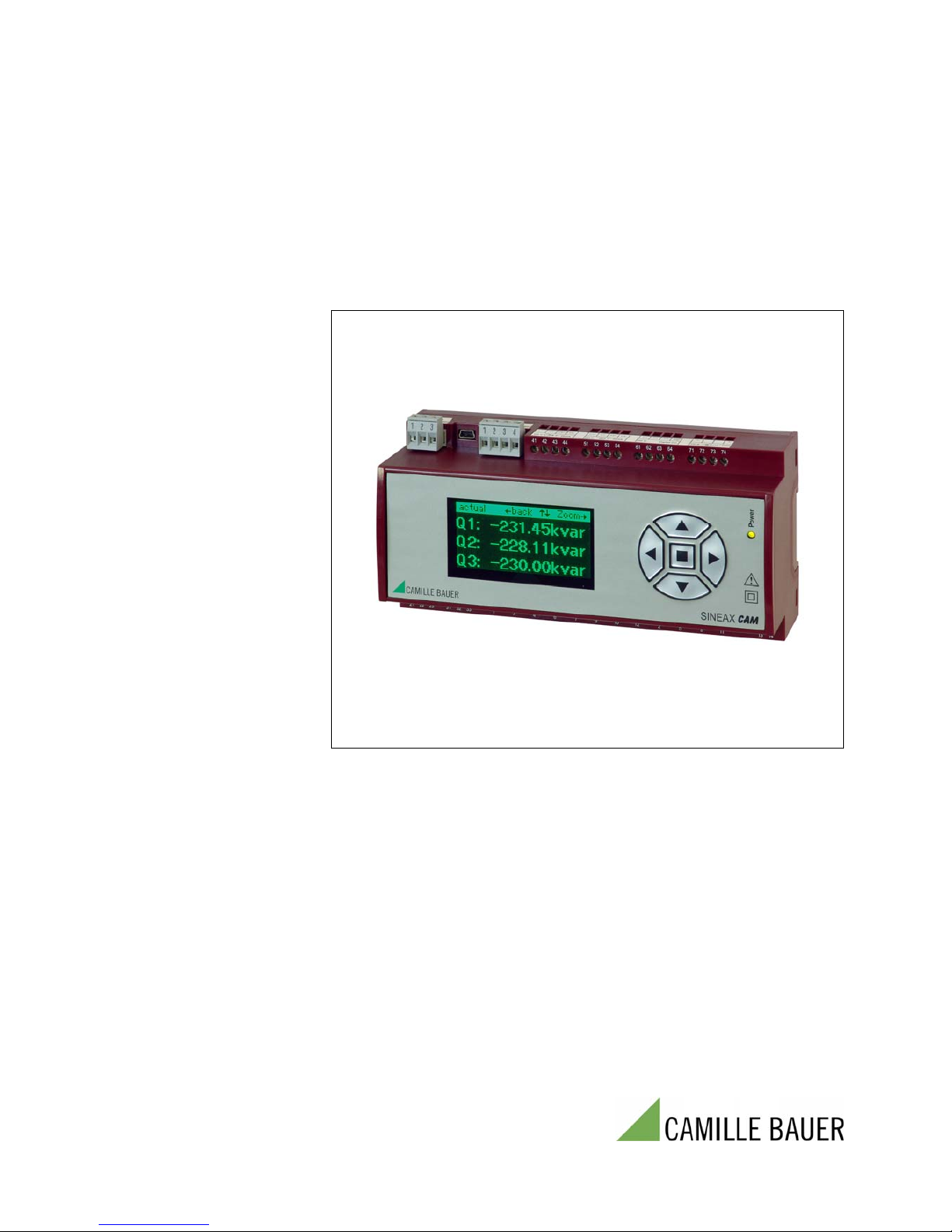
Graphic display for SINEAX CAM
CAM Display Be 156 861-01 06.10
Camille Bauer AG
Aargauerstrasse 7
CH-5610 Wohlen / Switzerland
Phone +41 56 618 21 11
Fax +41 56 618 35 35
e-mail: info@camillebauer.com
http://www.camillebauer.com


Overview
The optional graphic display is intended for on-site visualization of measurement data, lists and
alarms of the SINEAX CAM. The operation of the display is performed by means of the keys.
Using the keys the user may acknowledge alarms or extreme values as well. Which data can be
displayed depends on the version of the device, especially which I/O modules are present and
which options are activated. Also the configuration of the measurement unit influences the data
display. The most influencing factor in this context is the connected system.
The parametrization of the graphic display and the assembly of user specific measurement
displays are done using the CB-Manager Software. But settings like contrast or display language
may also be performed by means of the operating keys.
Content
1. Display structure and operation .............................................................................................. 4
2. Settings...................................................................................................................................... 5
2.1 Settings of the display ........................................................................................................... 5
2.2 Settings of the interface......................................................................................................... 5
2.3 Settings of the clock .............................................................................................................. 6
3. Security system ........................................................................................................................ 7
4. Display measurements ............................................................................................................. 8
4.1 Customer specific measurement displays ............................................................................. 8
4.2 Measurement display of system quantities............................................................................ 9
4.3 Measurement display of harmonics ..................................................................................... 10
4.4 Display meter contents ........................................................................................................ 11
4.5 Measurements of I/O's and relays ....................................................................................... 11
4.6 Measurement display of mean values ................................................................................. 12
4.7 Measurements for wiring control.......................................................................................... 13
5. Alarms...................................................................................................................................... 14
6. Lists.......................................................................................................................................... 15
7. Logger...................................................................................................................................... 18
8. Menu overview ........................................................................................................................ 19
3
1. Display structure and operation
Generally
When first switching on the device the main
menu is displayed. On every further start-up the
last displayed image before the power-down is
shown. There may be exceptions after a
reconfiguration of the device via interface, if the
displayed information is no longer available.
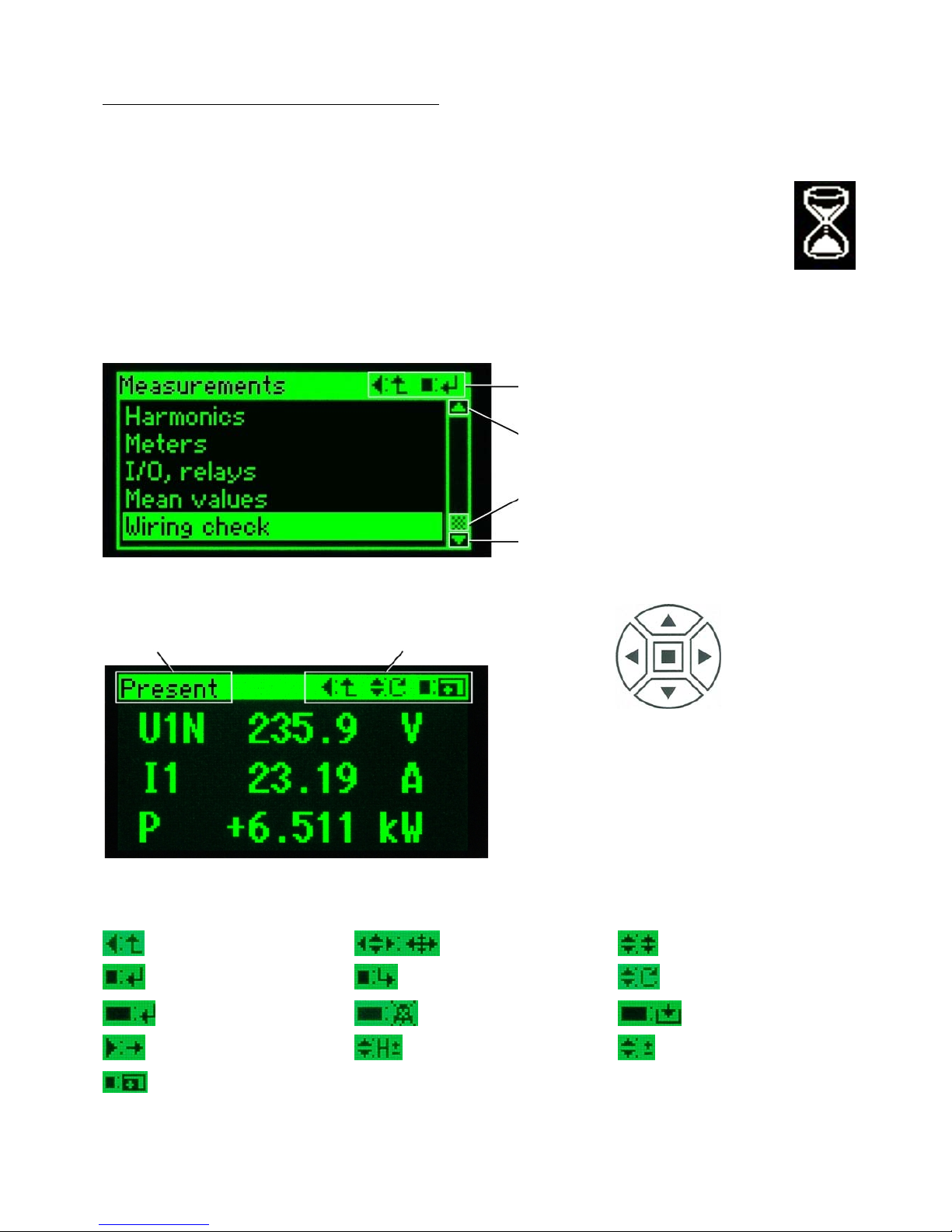
When changing the display window
there may be a waiting time, which is
symbolized by displaying a sand
glass. This way it can be prevented
that out-of-date data is displayed.
Selection menus
e: = Back to previous menu
: = Execute the selected line
S: Shift the selection up
Scroll position: If displayed, the list
contains more entries than can be displayed
at the same time
T: Shift the selection up
Menu description
as a navigation help
Operating menu
(possible functions)
The operation of the display is performed using
the keys. The symbols displayed in the
operating menu correspond to the symbols on
the keys. The assigned function is stated
behind the colon.
Overview of the used operating functions
Back to the previous
displayed menu
Positioning using the
cursor keys
Positioning upwards or
downwards
Perform selection
Adopt selected item
Display page ±
Perform selection,
press longer (>1s)
Alarm acknowledge,
press longer (>1s)
Reset selected item,
press longer (>1s)
Go to next parameter
Harmonic ±
Adjust value ±
Enlarge / downsize:
Number of measurements, scaling
4
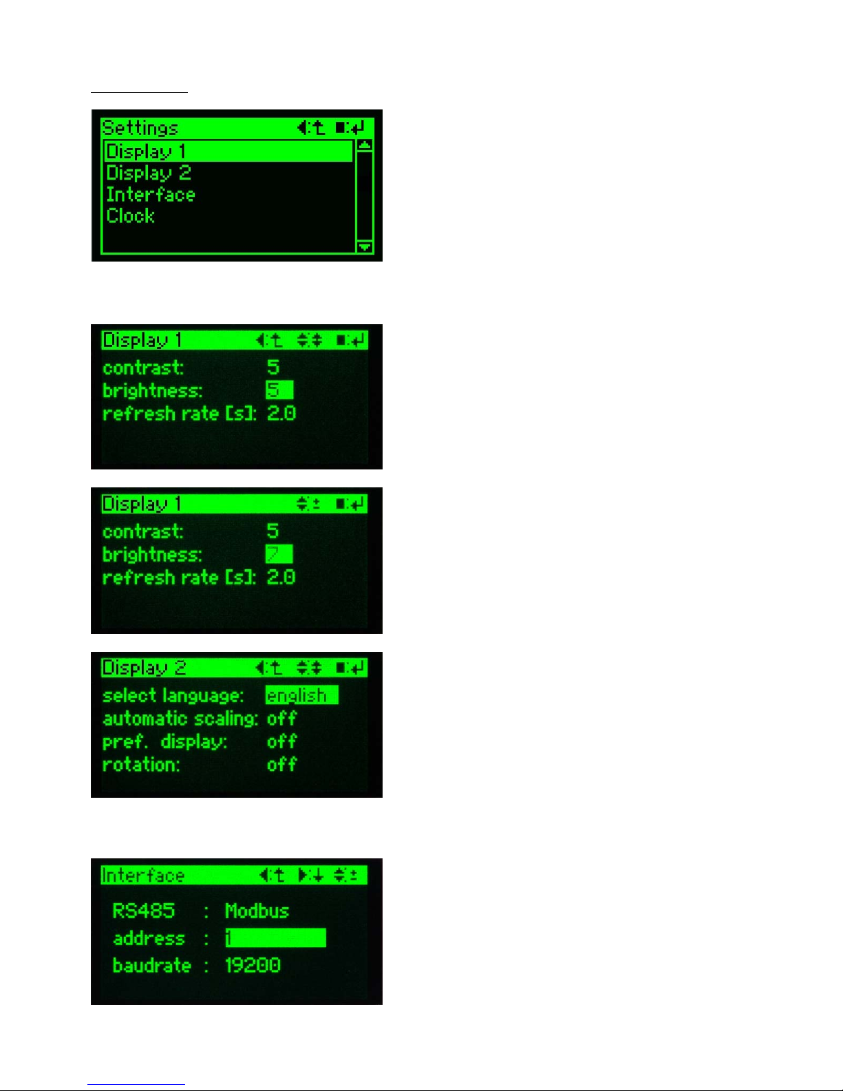
2. Settings
select a parameter group
Invoke the line settings in the main menu. This
line will be visible only if the selection is shifted
downwards. In the menu settings go to the line
with the desired parameter group using the
keys S and T. Then invoke the corresponding
parameter page by pressing the key .
2.1 Settings of the display
parameter selection
Position to the parameter which should be
modified using the keys S and T. Press to
see the value start flashing. Subsequent the
possible functions of the operating menu
change.
modifying parameters
The parameter can now be adjusted to the
desired value using the keys S and T. After
pressing the key again the value will be
adopted and stops flashing. The operating
menu changes back. Repeat the procedure for
other parameters.
display 2
Preference display and rotation are features of
the customer specific measurement displays
(see page 8). Auto scaling adjusts the representation to the measurement value. This way
and if input signals are low more digits are
shown, but maybe are not significant.
2.2 Settings of the interface
adjust Modbus parameters
Following the procedure used in 2.1 modify the
parameters device address and the baud rate
to your needs.
Attention: All devices connected to the Modbus
must have the same baud rate.
5
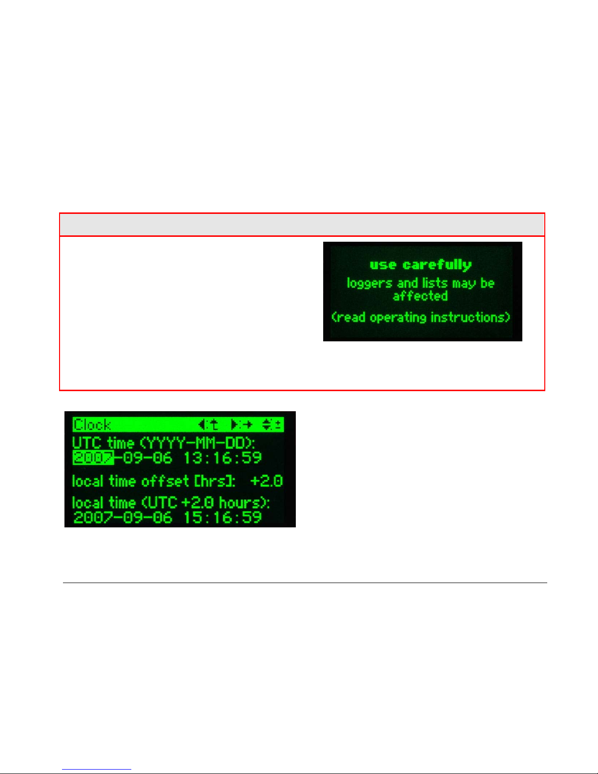
2.3 Settings of the clock
The SINEAX CAM has an internal clock, which
is used as a time reference for alarms, events,
progression of measurements and so on. Due
to the daylight saving time used in many
regions the time must to be set forward once a
year and backward once a year as well.
Especially when setting back the time
information gets lost, because data for this time
is acquired twice but can be stored only once.
To handle this problem the SINEAX CAM uses
internally UTC time only (see below). The user
can set a time offset, which performs a static
time shift to the local time. This way time
references shown on the display are correct. In
countries where a change to daylight saving
time is performed, the offset of normally one
hour has to be adjusted at the beginning and at
the end of the daylight saving time.
A T T E N T I O N !
A modification of the UTC time has a serious
impact on logger and lists. If e.g. the time is
shifted into the past, no entry can be made into
the logger or lists until the UTC time is at least
equal to the one used for the last entry. Only
this way the consistency of the already
recorded data can be guaranteed. The only
alternative is the complete reset of all logger
and list data. Therefore the following warning is
displayed before the clock data:
However, a modification of the local time
offset is harmless.
changing of parameters
There is no need for a special modification
mode. The flashing value can be modified
directly using the keys S and T. To go on to
the next parameter use X. The take over of the
data is not performed before the return to the
menu settings.
UTC (Universal Time Coordinated)
Sometimes UTC is called world time as well. The
reference corresponds to the Greenwich Mean
Time (GMT). The time zones of the world
nowadays are all referenced with an offset to
UTC. UTC time doesn't use time shifts, which
may occur due to a change to daylight saving
time.
Example: In Switzerland the CET (Central
European Time) is valid, which has an offset of
+1[h] to UTC. But during have of the year the CEST
(Central European Summer Time) is used, which
has an offset of +2[h] to the UTC time used in the
SINEAX CAM.
6
 Loading...