

Device handbook
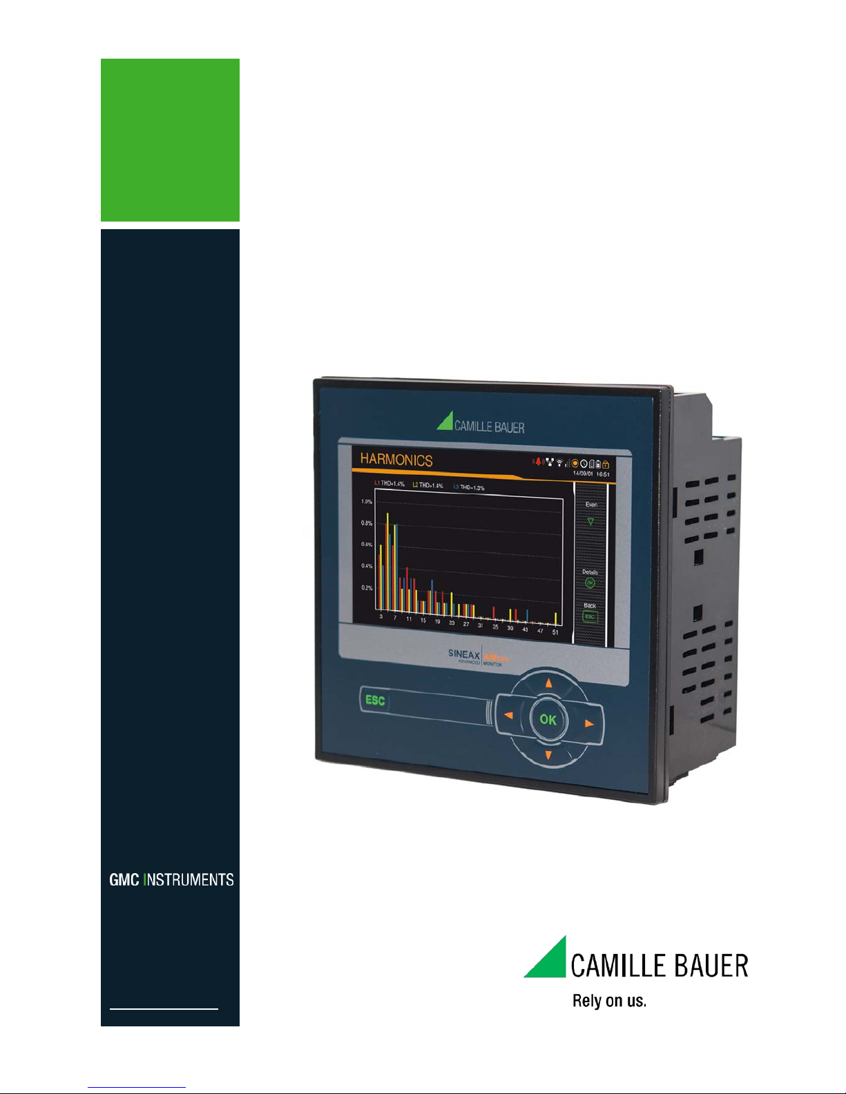
SINEAX AM200 0
Operating Instructions SINEAX AM2000
173 849 04/2015
Camille Bauer Metrawatt AG
Aargauerstr asse 7
CH-5610 Wohlen / Switzerland
Phone: +41 56 618 21 11
Telefax: +41 56 618 35 35
E-Mail: info@cbmag.com
http://www.camillebauer.com
2/62 Device handboo k SINEAX AM2000, 173 849, 04/2015
Legal information
Warning notices
In this document warning notices are used, which you have to observe to ensure personal safety and to prevent
damage to property. Depending on the degree of danger the following symbols are used:
If the warning notice is not followed death or severe personal injury
will result.
If the warning notice is not followed damage to property or severe
personal injury may result.
If the warning notice is not followed the device may be damaged or
may not fulfill the expected functionality.
Qualified personnel
The product described in this document may be handled by personnel only, which is qualified for the respective
task. Qualified personnel have the training and experience to identify risks and potential hazards when working
with the product. Qualified personnel are also able to understand and follow the given safety and warning
notices.
Intended use
The product described in this document may be used only for the application specified. The maximum electrical
supply data and ambient conditions specified in the technical data section must be adhered. For the perfect and
safe operation of the device proper transport and storage as well as professional assembly, installation,
handling and maintenance are required.
Disclaimer of liability
The content of this document has been reviewed to ensure correctness. Nevertheless it may contain errors or
inconsistencies and we cannot guarantee completeness and correctness. This is especially true for different
language versions of this document. This document is regularly reviewed and updated. Necessary corrections
will be included in subsequent version and are available via our webpage http://www.camillebauer.com
.
Feedback
If you detect errors in this document or if there is necessary information missing, please inform us via e-mail to:
customer-support@camillebauer.com

3/62 Device handboo k SINEAX AM2000, 173 849, 04/2015
Contents
1. Introduction ..................................................................................................................... 5
1.1 Purpose of this document ........................................................................................................ 5
1.2 Scope of supply ....................................................................................................................... 5
1.3 Further documents .................................................................................................................. 5
2. Safety notes ..................................................................................................................... 6
3. Device overview............................................................................................................... 6
3.1 Brief description ....................................................................................................................... 6
3.2 Available measurement data ................................................................................................... 6
4. Mechanical mounting ...................................................................................................... 7
4.1 Panel cutout ............................................................................................................................ 7
4.2 Mounting of the device ............................................................................................................ 7
4.3 Demounting of the device ........................................................................................................ 7
5. Electrical co n nect io ns .................................................................................................... 8
5.1 General safety notes ............................................................................................................... 8
5.2 Terminal assignments of the I/O extensions ............................................................................ 9
5.3 Possible cross sections and tightening torques ....................................................................... 9
5.4 Inputs .................................................................................................................................... 10
5.5 Power supply ......................................................................................................................... 19
5.6 Relays ................................................................................................................................... 19
5.7 Digital inputs and outputs ...................................................................................................... 19
5.8 Analog outputs ...................................................................................................................... 20
5.9 Modbus interface RS485 ....................................................................................................... 21
6. Commissioning.............................................................................................................. 22
6.1 Parametrization of the device functionality ............................................................................. 22
6.2 Installation check ................................................................................................................... 23
6.3 Simulation of I/Os .................................................................................................................. 23
7. Operating the device ..................................................................................................... 24
7.1 Operating elements ............................................................................................................... 24
7.2 Selecting the information to display ....................................................................................... 24
7.3 Measurement displays and used symbols ............................................................................. 25
7.4 Alarming ................................................................................................................................ 27
7.5 Resetting measurements ....................................................................................................... 29
7.6 Setting / resetting of meter contents ...................................................................................... 29
7.7 Configuration ......................................................................................................................... 29
7.8 Timeouts ............................................................................................................................... 30
8.1 Calibration and new adjustment ............................................................................................ 31
8.2 Cleaning ................................................................................................................................ 31
8.3 Battery ................................................................................................................................... 31
8.4 Disposal ................................................................................................................................ 31
9. Technical data ............................................................................................................... 32
10. Di m ensional drawings .................................................................................................. 38

4/62 Device handboo k SINEAX AM2000, 173 849, 04/2015
Annex ................................................................................................................................... 39
A Description of measured quantities ............................................................................. 39
A1 Basic measurements............................................................................................................. 39
A2 Harmonic analysis ................................................................................................................. 43
A3 System imbalance ................................................................................................................. 44
A4 Mean values and trend .......................................................................................................... 45
A5 Meters ................................................................................................................................... 46
B Display matrices ............................................................................................................ 47
B0 Used abbreviations for the measurements ............................................................................ 47
B1 Display matrices for single phase system .............................................................................. 51
B2 Display matrices for split-phase (two-phase) systems ........................................................... 52
B3 Display matrices for 3-wire system, balanced load ................................................................ 53
B4 Display matrices for 3-wire systems, unbalanced load .......................................................... 54
B5 Display matrices for 3-wire systems, unbalanced load, Aron ................................................. 55
B6 Display matrices for 4-wire system, balanced load ................................................................ 56
B7 Display matrices for 4-wire systems, unbalanced load .......................................................... 57
B8 Display matrices for 4-wire system, unbalanced load, Open-Y .............................................. 58
C Logic functions ............................................................. Fehler! Textmarke nicht definiert.
D Declaration of conformity ............................................................................................. 60
D1 CE conformity ....................................................................................................................... 60
D2 FCC statement ...................................................................................................................... 61
INDEX ................................................................................................................................... 62

5/62 Device handboo k SINEAX AM2000, 173 849, 04/2015
1. Introduction
1.1 Purpose of this document
This document describes the universal measurement device for heavy-current quantities SINEAX
AM2000. It is intended to be used by:
• Installation personnel and commissioning engineers
• Service and maintenance personnel
• Planners
Scope
This handbook is valid for all hardware versions of the AM2000. Some of the functions described in this
document are available only, if the necessary optional components are included in the device.
Required knowledge
A general knowledge in the field of electrical engineering is required. For assembly and installation of the
device knowledge of applicable national safety regulations and installation standard is required.
1.2 Scope of supply
• Measurement SINEAX AM2000
• Saf ety instructions (multiple languages)
• Connection set: 2 mounting clamps
1.3 Further documents
The following documents are provided elec tr onica lly via http://www.camillebauer.com/am2000-en :
• Safety instructions SINEAX AM2000
• Data sheet SINEAX AM2000
• Modbus basics: General description of the communication protocol
• Modbus interface SINEAX AM2000: Register description of Modbus/RTU communication via RS-485
6/62 Device handboo k SINEAX AM2000, 173 849, 04/2015
2. Safety notes
Device may only be disposed in a professional manner !
The installation and commissioning should only be carried out by trained personnel.
Check the following points before commissioning:
– that the maximum values for all the connections are not exceeded, see "Technical data"
section,
– that the connection wires are not damaged, and that they are not live during wiring,
– that the power flow direction and the phase rotation are correct.
The instrument must be taken out of service if safe operation is no longer possible (e.g. visible
damage). In this case, all the connections must be switched off. The instrument must be
returned to the factory or to an authorized service dealer.
It is forbidden to open the housing and to make modifications to the instrument. The instrument
is not equipped with an integrated circuit breaker. During installation check that a labeled switch
is installed and that it can easily be reached by the operators.
Unauthorized repair or alteration of the unit invalidates the warranty.
3. Device overview
3.1 Brief description
The SINEAX AM2000 is a c omprehensive instr ument for the universal measurement and monitori ng in
power systems. A full par ameterization of all functions of the AM2000 is possible directly at the devic e.
The universal meas urem ent system of the de vice m a y be used direc tl y for an y po wer s ystem , fr om single
phase up to 4-wire unbalanced networks, without hardware modifications.
Using additional, optional components the opportunities of the AM2000 may be extended. You may
choose from I/O extensions or Modbus/RTU com m unicatio n interf ace. The nameplate on the device g ives
further details about the present version.
3.2 Available measurement data
The SINEAX AM2000 provides measurements in the following subcategories:
a) Instantaneous values : Pres ent T RMS va lues and associated min/max values
b) Energy consumption: Power mean-values with trend and history as well as energy meters
c) Harmonics: Total harmonic distortion THD/TDD, individual harmonics and their maximum values
d) Phasor diagram: Graphical overview of all current and voltage phasors
e) Alarms: State display of monitored events
7/62 Device handboo k SINEAX AM2000, 173 849, 04/2015
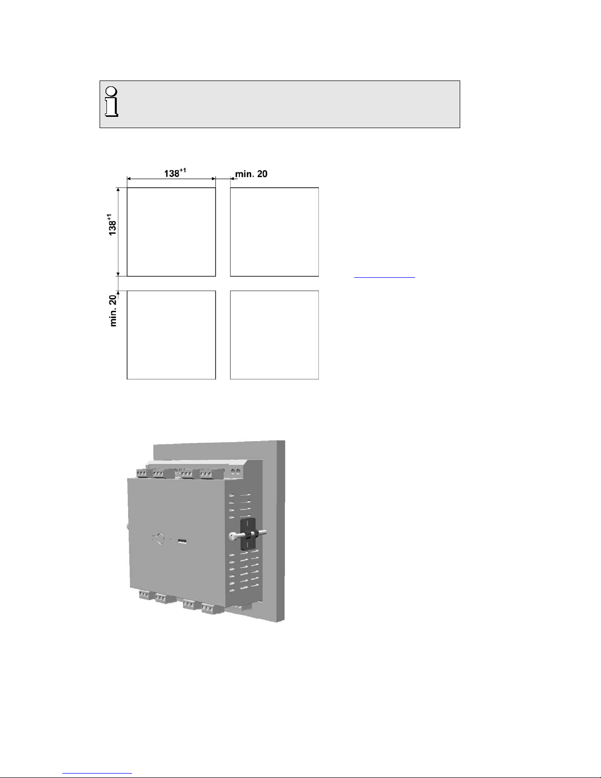
4. Mechanical mounting
► The AM2000 is designed for panel mounting
Please ensure that the operating temperature limits are not exceeded when
determining the place of mounting (place of measurement):
-10 ... 55°C
4.1 Panel cutout
Dimensional drawing AM2000:
See section 10
4.2 Mounting of the device
The device is suitable for panel widths up to 8mm.
a) Slide the device into the cutout from
the outside
b) From the side slide in th e m ounting
clamps into the intended openings and
pull them back about 2 mm
c) Tighten the fixation screws until the
device is tightly fixed with the panel
4.3 Demounting of the device
The demounting of the device may be performed only if all connected wires are out of service. Remove
all plug-in terminals and all connections of the current and voltage inp uts . Pay attention to the fact, that
current transformers must be shortened before removing the current connections to the device. Then
demount the device in the opposite order of mounting (4.2).
8/62 Device handboo k SINEAX AM2000, 173 849, 04/2015
5. Electrical connecti ons
Ensure under all circumstances that the leads are free of potential
when connecting them !
5.1 General safety notes
Please observe that the data on the type plate must be adhered to !
The national provisions have to be observed in the installation and material selection of electric lines,
e.g. in Germany VDE 0100 “Conditions concerning the erection of heavy current facilities with rated
voltages below 1000 V”!
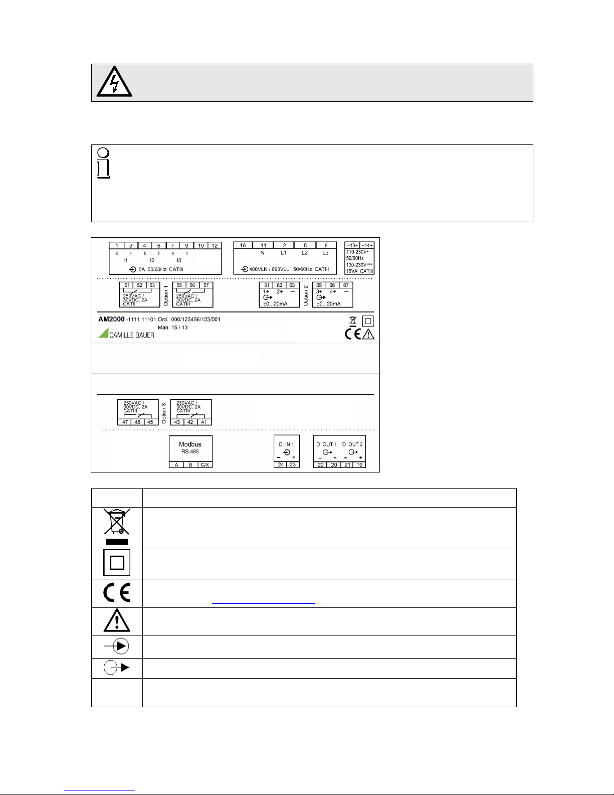
Nameplate of a device with
• Modbus/RTU interface
• 4 relay outputs
• 4 analog outputs
Symbol Meaning
Device may only be disposed of in a professional manner!
Double insulation, device of protection class 2
CE conformity mark. The device fulfills the requirements of the applicable EC
directives. See declaration of conformity.
Caution! General hazard point. Read the operating instructions.
General symbol: Input
General symbol: Output
CAT III
Measurement category CAT III for current / voltage inputs, power supply and relay
outputs

9/62 Device handboo k SINEAX AM2000, 173 849, 04/2015
5.2 Terminal assignments of the I/O extensions
Function Option 1 Option 2 Option 3 Option 4
2 relay outputs
1.1: 51,52,53
1.2: 55,56,57
2.1: 61,62,63
2.2: 65,66,67
3.1: 41,42,43
3.2: 45,46,47
4.1: 31,32,33
4.2: 35,36,37
2 analog outputs
1.1: 51(+), 53(-)
1.2: 52(+), 53(-)
2.1: 61(+), 63(-)
2.2: 62(+), 63(-)
3.1: 41(+), 43(-)
3.2: 42(+), 43(-)
4.1: 31(+), 33(-)
4.2: 32(+), 33(-)
4 analog outputs
1.1: 51(+), 53(-)
1.2: 52(+), 53(-)
1.3: 55(+), 57(-)
1.4: 56(+), 57(-)
2.1: 61(+), 63(-)
2.2: 62(+), 63(-)
2.3: 65(+), 67(-)
2.4: 66(+), 67(-)
3.1: 41(+), 43(-)
3.2: 42(+), 43(-)
3.3: 45(+), 47(-)
3.4: 46(+), 47(-)
4.1: 31(+), 33(-)
4.2: 32(+), 33(-)
4.3: 35(+), 37(-)
4.4: 36(+), 37(-)
5.3 Possible cross sections and tightening torques
Inputs L1(2), L2(5), L3(8), N(11), I1(1-3), I2( 4-6), I3(7-9), power supply (13-14)
Single wire
1 x 0,5 ... 6.0mm2 or 2 x 0,5 ... 2.5mm
2
Multiwire with end splices
1 x 0,5 ... 4.0mm2 or 2 x 0,5 ... 2.5mm
2
Tightening torque
0.5…0.6Nm resp. 4.42…5.31 lbf in
I/O's, relays, RS485 connector (A, B, C/X)
Single wire
1 x 0.5 ... 2.5mm2 or 2 x 0.5 ... 1.0mm
2
Multiwire with end splices
1 x 0.5 ... 2.5mm2 or 2 x 0.5 ... 1.5mm
2
Tightening torque
0.5…0.6Nm resp. 4.42…5.31 lbf in
10/62 Device handbook SINEAX AM2000, 173 849, 04/2015
5.4 Inputs
All voltage measurement inputs must originate at circuit breakers or fuses rated 5 Amps or
less. This does not apply to the neutral connector. You have to provide a method for
manually removing power from the device, such as a clearly labeled circuit breaker or a
fused disconnect switch.
When using voltage transformers you have to ensure that their secondary connections
never will be short-circuited.
No fuse may be connected upstream of the current measurement inputs !
When using current transformers their secondary connectors must be short-circuited
during installation and before removing the device. Never open the secondary circuit under
load.
The connection of the inputs depends on the configured system (connection type).

11/62 Device handbook SINEAX AM2000, 173 849, 04/2015
Single-phase AC mains
L1
N
L1 L2 L3
N
I1
31
I2
4
I3
97
IN
PE
6
10 12 16
11 2 5 8
5 A
(UL listed)
Direct connection
L1
N
L1 L2 L3
N
I1
31
I2
4
I3
97
IN
PE
6
10 12 16
11 2 5 8
5 A
(UL listed)
K
k
L
l
With current transformer
L1
N
K
k
L
l
L
1 L2
L3
N
I1
31
I
2
4
I
3
9
7
IN
PE
6
10 12 16
11 2
5 8
5 A
(
UL listed)
v
V
u
U
With current and voltage transformer
12/62 Device handbook SINEAX AM2000, 173 849, 04/2015
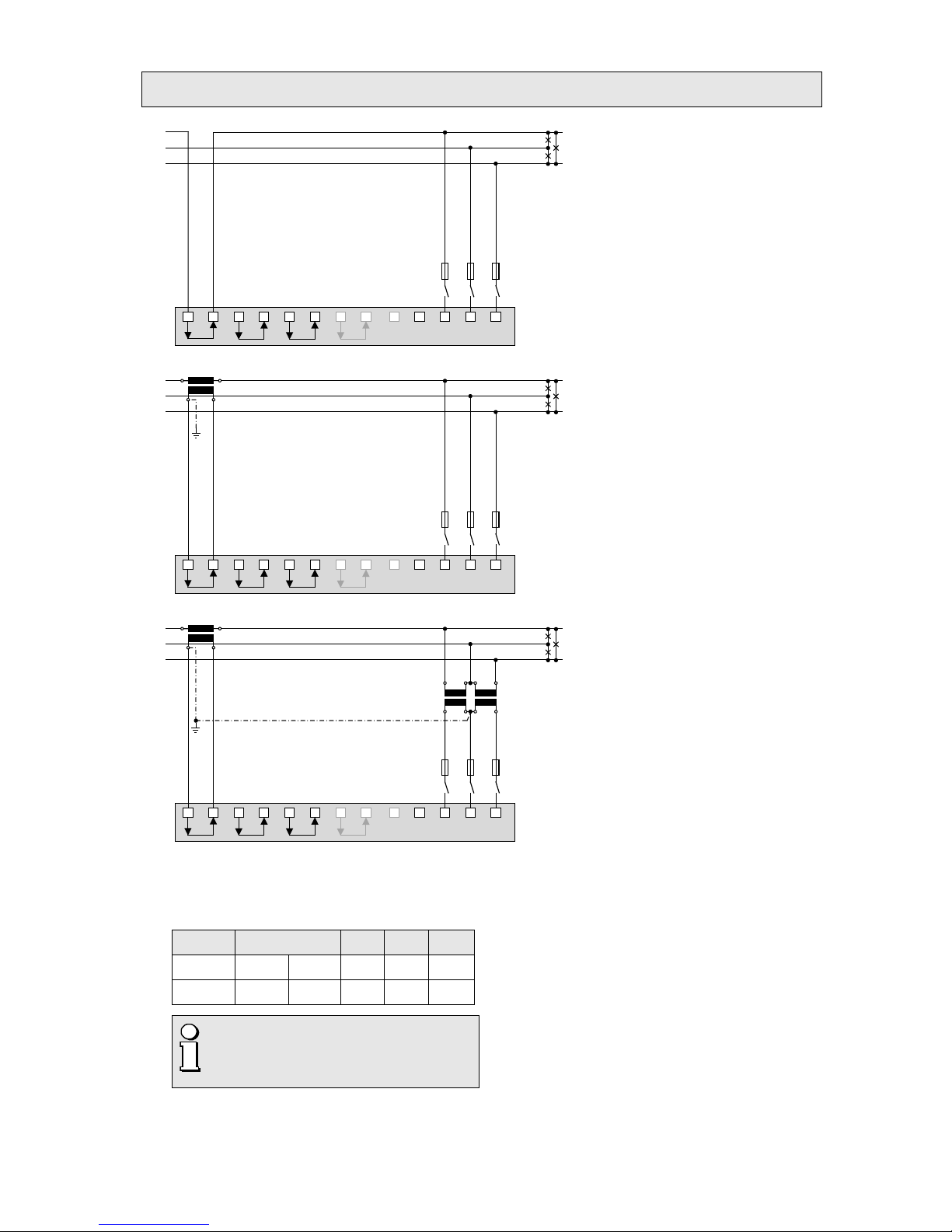
Three wire system, balanced load, current measurement via L1
L1
L2
L3
L1 L2 L3
N
I1
31
I2
4
I3
97
IN
PE
6
10 12 16
11
2 5 8
5 A
(UL listed)
Direct connection
L1
L2
L3
K
k
L
l
L1
L2
L3
N
I1
31
I2
4
I
3
97
IN
PE
6
10
12 16
11 2
5 8
5 A
(UL listed
)
With current transformer
L1
L2
L3
K
k
L
l
L1 L2 L3
N
I1
31
I2
4
I3
97
IN
PE
6
10 12 16
11 2 5 8
5 A
(UL listed)
u
U
v
V
u
U
v
V
With current and voltage transformers
In case of current measurement via L2 or L3 connect voltages
according to the following table:
Current Terminals L1 L2 L3
L2 I1-1 I1-3 L2 L3 L1
L3 I1-1 I1-3 L3 L1 L2
By rotating the voltage connections the
measurements U12, U23 and U31 will be
assigned interchanged !
13/62 Device handbook SINEAX AM2000, 173 849, 04/2015
Four wire system, balanced load, current measurement via L1
L
1
L
2
L
3
N
L
1 L
2
L3
N
I1
31
I
2
4
I
3
9
7
IN
PE
6
10 12
16
11 2
5 8
5 A
(
UL listed)
Direct connection
L1
L2
L3
N
K
k
L
l
L1 L2 L
3
N
I1
31
I2
4
I3
9
7
IN
PE
6
10 12 16
11 2 5 8
5 A
(UL listed)
With current transformer
L1
L2
L3
N
K
k
L
l
L1 L2 L3
N
I1
31
I2
4
I3
9
7
IN
PE
6
10 12 16
11
2
5 8
5 A
(UL listed)
V
v
U
u
With current and voltage transformer
In case of current measurement via L2 or L3 connect vol tage s
according to the following table:
Current Terminals L1 N
L2 I1-1 I1-3 L2 N
L3 I1-1 I1-3 L3 N
14/62 Device handbook SINEAX AM2000, 173 849, 04/2015
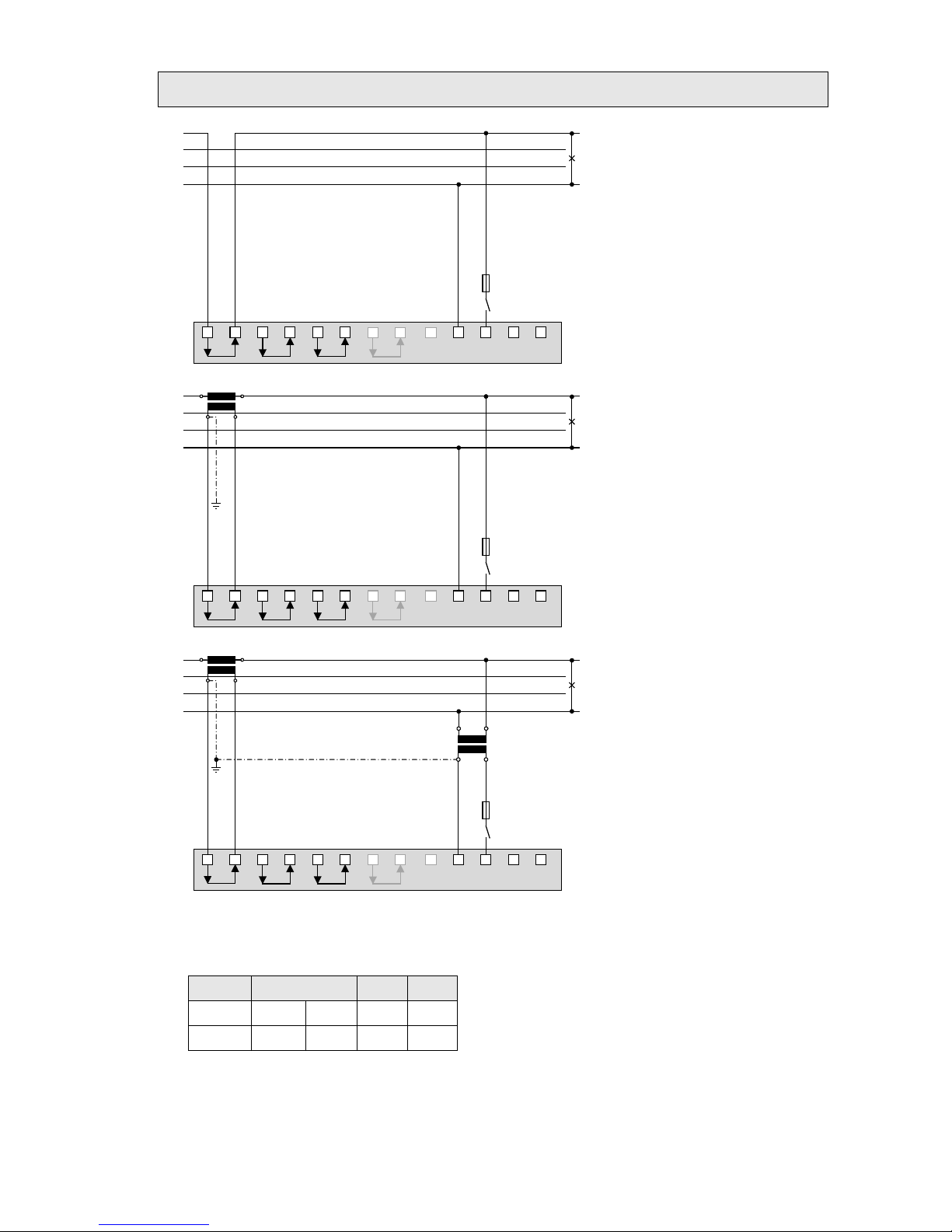
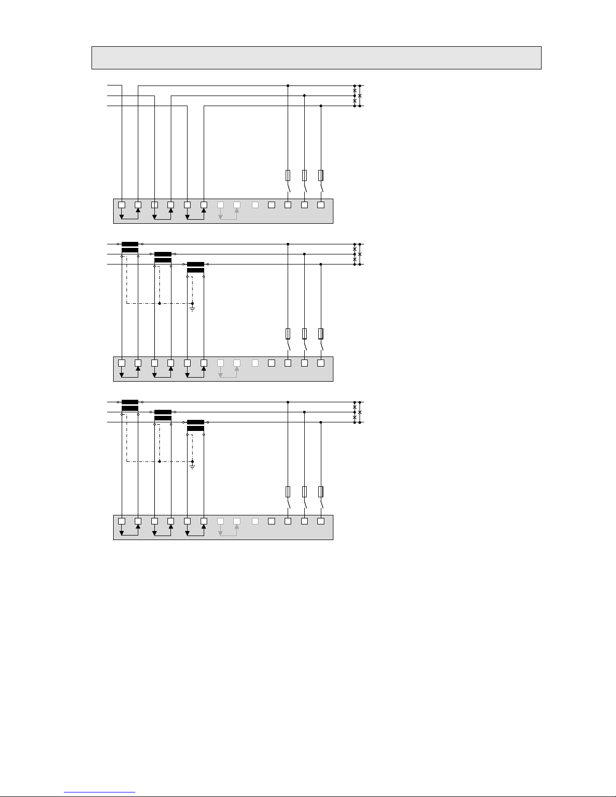
Three wire system, unbalanced load
L1
L2
L3
L1 L2 L3
N
I1
31
I2
4
I3
97
IN
PE
6
10 12 16
11
2 5 8
5
A
(UL listed)
Direct connection
L
1
L2
L
3
K
k
L
l
K
k
L
l
K
k
L
l
L
1
L2 L
3
N
I1
31
I
2
4
I
3
9
7
IN
PE
6
10 12 16
11
2 5
8
5
A
(
UL listed)
With current transformers
L1
L
2
L3
K
k
L
l
K
k
L
l
K
k
L
l
L1 L2 L
3
N
I1
31
I2
4
I3
97
IN
PE
6
10 12 16
11 2 5 8
5 A
(UL listed)
With current and 3 single-pole isolated
voltage transformers
15/62 Device handbook SINEAX AM2000, 173 849, 04/2015
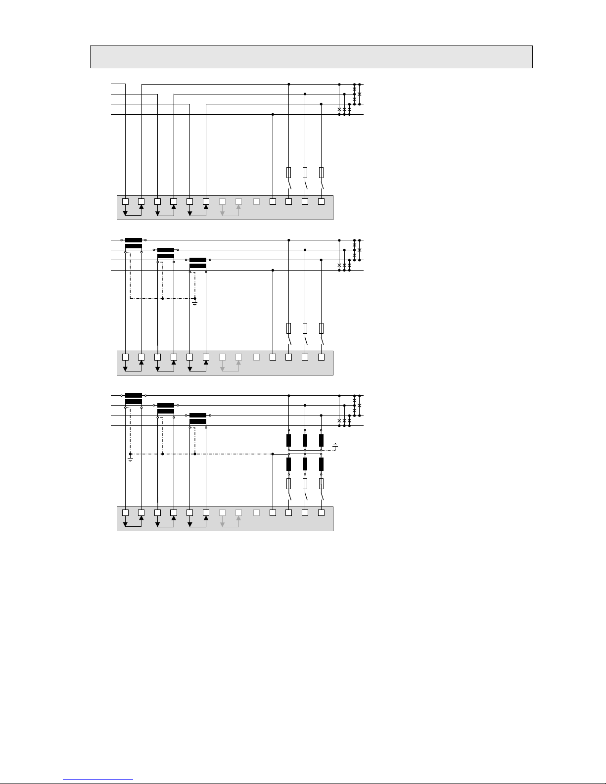
Three wire system, unbalanced load, Aron connection
L1
L2
L3
L1 L2 L3
N
I1
31
I2
4
I3
97
IN
PE
6
10 12 16
11 2 5 8
5 A
(UL listed)
Direct connection
L1
L2
L3
K
k
L
l
K
k
L
l
L1 L2 L3
N
I1
31
I2
4
I3
97
IN
PE
6
10 12 16
11 2 5 8
5 A
(UL listed)
With current transformers
L1
L2
L3
K
k
L
l
K
k
L
l
L
1 L2 L3
N
I1
31
I
2
4
I3
97
IN
PE
6
10
12 16
11
2 5 8
x
u
X
U
X
U
X
U
x
u
x
u
5 A
(UL listed
)
With current and 3 single-pole isolated
voltage transformers
16/62 Device handbook SINEAX AM2000, 173 849, 04/2015
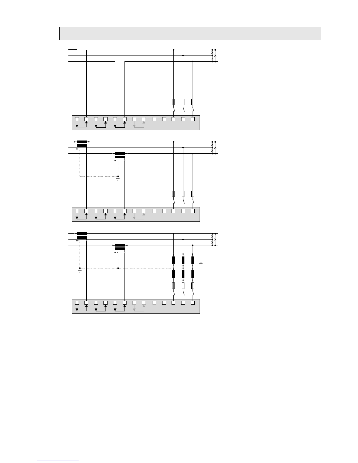
Four wire system, unbalanced load
L1
L2
L3
N
L1 L2 L3
N
I1
31
I2
4
I3
97
IN
PE
6
10 12 16
11
2 5 8
5
A
(UL listed)
Direct connection
L1
L
2
L3
N
K
k
L
l
K
k
L
l
K
k
L
l
L
1 L2
L3
N
I1
31
I
2
4
I3
97
IN
PE
6
10 12 16
11
2 5
8
5
A
(
UL listed)
With current transformer
L1
L2
L3
N
K
k
L
l
K
k
L
l
K
k
L
l
L1 L2
L3
N
I1
31
I2
4
I
3
97
IN
PE
6
10 12 16
11 2 5 8
x
u
X
U
X
U
X
U
x
u
x
u
5 A
(UL listed)
With current and 3 single-pole isolated
voltage transformers
17/62 Device handbook SINEAX AM2000, 173 849, 04/2015
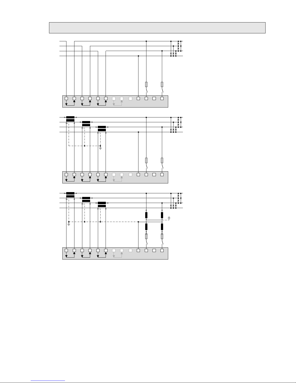
Four wire system, unbalanced load, Open-Y
L1
L2
L
3
N
L1 L2 L3
N
I1
31
I2
4
I
3
97
IN
PE
6
10
12 16
11 2
5
8
5
A
(
UL listed
)
Direct connection
L1
L
2
L
3
N
K
k
L
l
K
k
L
l
K
k
L
l
L
1 L2
L3
N
I1
31
I2
4
I
3
97
IN
PE
6
10
12
16
11
2 5
8
5 A
(
UL listed)
With current transformers
L1
L2
L3
N
K
k
L
l
K
k
L
l
K
k
L
l
L1 L2
L3
N
I1
31
I2
4
I3
97
IN
PE
6
10 12 16
11 2 5
8
x
u
X
U
X
U
x
u
5
A
(
UL listed)
With current and 2 single-pole isolated
voltage transformers
18/62 Device handbook SINEAX AM2000, 173 849, 04/2015
Split-phase ("two phase system"), unbalanced load
L1
L2
N
L1 L2 L3
N
I1
31
I2
4
I3
97
IN
PE
6
10 12 16
11 2 5 8
5 A
(UL listed)
Direct connection
L1
L2
N
K
k
L
l
K
k
L
l
L1 L
2 L3
N
I1
3
1
I2
4
I3
97
IN
PE
6
10 12 16
11
2 5 8
5 A
(UL listed)
With current transformers
19/62 Device handbook SINEAX AM2000, 173 849, 04/2015
5.5 Power supply
A marked and easily accessible curre nt limiting switch has to be arranged in the vicinity of
the device for turning off the power supply. Fusing should be 10 Amps or less and must be
rated for the available voltage and fault current.
5.6 Relays
When the device is switched off the relay contacts are de-energized, but dangerous
voltages may be present.
Relays are available for device versions with
corresponding I/O extensions only.
I/O extension y x
1 5
2 6
3 4
4 3
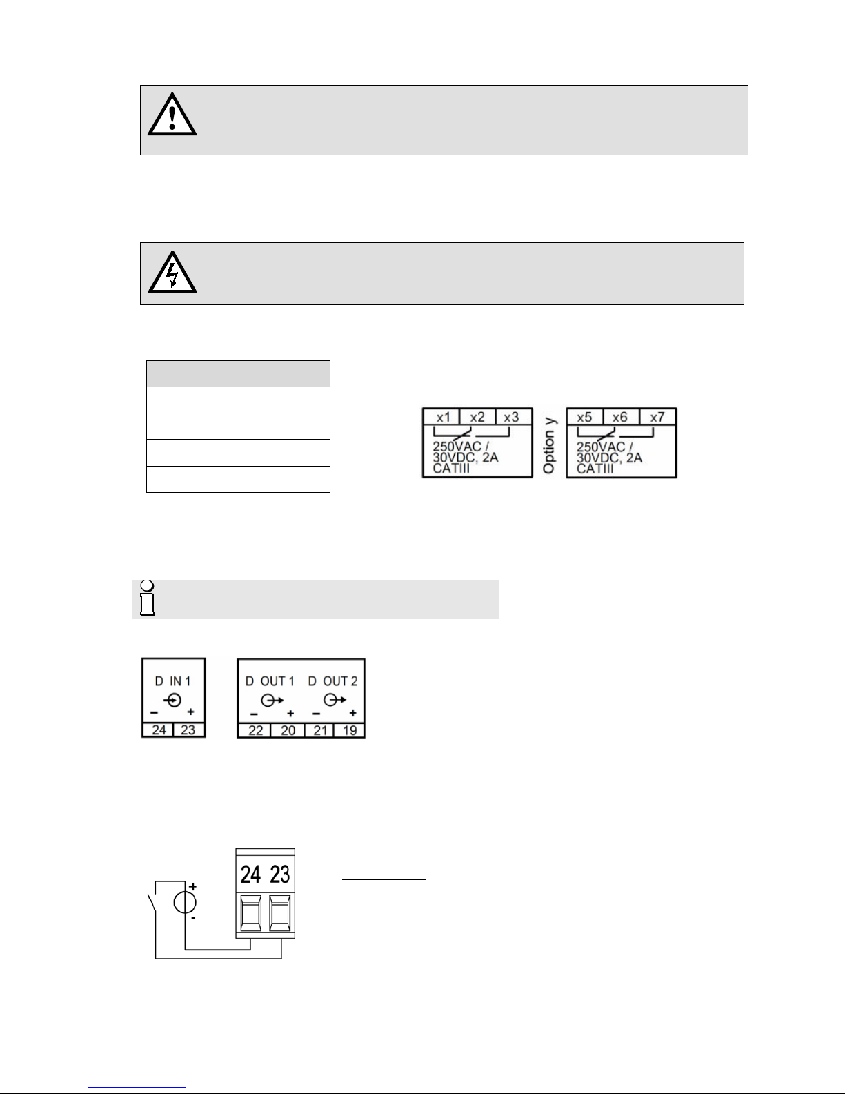
5.7 Digital inputs and outputs
For the digital inputs / outputs an external power supply of 12 / 24V DC is required.
The power supply shall not exceed 30V DC !
A digital input and two digital outputs are provided as a standard.
Usage as digital input
► Clock synchronization
► Synchronization of billing intervals in accordance with energy provider
► Meter tariff switching
Technical data
Input current < 7,0 mA
Logical ZERO - 3 up to + 5 V
Logical ONE 8 up to 30 V

20/62 Device handbook SINEAX AM2000, 173 849, 04/2015
Usage as digital output
► Alarm output
► State reporting
► Pulse output to an external counter (acc. EN62053-31)
1) Recommended if input
impedance of counter > 100 kΩ
Driving a counter mechanism
The width of the energy pulses can be selected, but
have to be adapted to the counter mechanism.
Electro mechanical meters typically need a pulse
width of 50...100ms.
Electronic meters are par t l y capable to detec t puls es
in the kHz range. There are the types NPN (active
negative edge) and PNP (active positive edge). For
the AM2000 a PNP type is required. T he pulse w idth
has to be at least 30ms (acc. EN62053-31). The delay
between to pulses corresponds at least to the pulse
width. The smaller the pulse width, the higher the
sensitivity to disturbances.
Driving a relay
Rated current 50 mA (60 mA max.)
Switching frequency (S0) ≤ 20 Hz
Leakage current 0,01 mA
Voltage drop < 3 V
Load capacity 400 Ω … 1 MΩ
5.8 Analog outputs
Analog outputs are available for devices with corresponding I/O extensions only. See nameplate.
Connection to an analog input card of a PLC or a
control system
The AM2000 is an isolated measurement device. The
particular outputs are not galvanically isolat ed. To
reduce the influence of disturbances shielded a
twisted-pair cables should be used. The shield should
be connected to earth on both opposite ends. If there
a potential differences between the ends of the cable
the shield should be earthed on one side only to
prevent from equalizing currents.
Under all circumstances consider as well appropriate
remarks in the instruction manual of the system to
connect.

21/62 Device handbook SINEAX AM2000, 173 849, 04/2015
5.9 Modbus interface RS485
Via the optional Modbus interface measurement data may be provided for a superior system. However,
the Modbus interface cannot be used for device parameterization.
1) One ground connection only.
This is possibly made within the
master (PC).
Rt: Termination resistors: 120 Ω each
for long cables (> approx. 10 m)
Rs: Bus supply resistors,
390 Ω each
The signal wires (A, B) have to be t wist ed. G ND ( C/X) can be connected via a wire or via th e cabl e s c reen.
In disturbed environments shielded cables must be used. Supply resistors (Rs) have to be present in bus
master (PC) interface. Stubs should be avoided when connecting the devices. A pure daisy chain network
is ideal.
You may connect up to 32 Modbus devices to the bus. A proper operation requires that all devices
connected to the bus have equal communication settings (baud rate, transmission format) and unique
Modbus addresses.
The bus system is operated half duplex and may be extended to a maximum length of 1200 m without
repeater.

22/62 Device handbook SINEAX AM2000, 173 849, 04/2015
6. Commissioning
Before commissioning you have to check if the connection data of the device match the data
of the plant (see nameplate).
If so, you can start to put the device into operation by switching on the power supply and the
measurement inputs.
Measurement input
Input voltage
Input current
System frequency
1 Works no.
2 Test and conformity marks
3 Assignment voltage inputs
4 Assignment current inputs
5 Assignment power supply
6 Load capacity relay outputs
6.1 Parametrization of the device functionality
A full parameterization of all functions of the device is possible directly at the device. See: Configuration

23/62 Device handbook SINEAX AM2000, 173 849, 04/2015
6.2 Installation check
By means of the phasor diagram the correct connection of the current and voltage inputs can be checked.
In this diagram a technical visualization of the current and voltage phasors is shown, using a counterclockwise rotation.
6.3 Simulation of I/Os
To check if subsequent circuits will work properly with the m eas urement data provided by the device,
using the service menu all analog, digital and relay outputs may be simulated, by predefining any output
value resp. discrete state.

24/62 Device handbook SINEAX AM2000, 173 849, 04/2015
7. Opera ti ng t he de vic e
7.1 Operating elements
Operation is performed by means of 6 keys:
4 keys for navigation (
, , , ) and
for the selection of values
OK for selection or confirmation
ESC for menu display, terminate or
cancel
The main function of the operating keys
changes in some measurement displays,
during parameterization and in service
functions. The valid functionality of the keys is
then shown in a help bar.
7.2 Selecting the information to display
Information selection is performed via menu.
Some menu items are direct selections, other
menu items contain up to two further menu
levels.
Displaying the menu
Press ESC. Each time the key is pressed a
change to a higher menu level is performed, if
present.
Displaying information
The menu item chosen using
, can be
selected using OK. Repeat the procedure in
possible submenus until the required information
is diaplyed.
Closing the menu
After 2 min. without interaction the menu is
automatically closed and the last active
measurement display is shown.

25/62 Device handbook SINEAX AM2000, 173 849, 04/2015
7.3 Measurement displays and used symbols
For displaying measurement information the device uses both numerical and numerical-graphical
measurement displays.
Examples Measurement information
1 measured quantity
2 measured quantities
4 measured quantities
2x4 measured quantities
Graphical measurement display
Further examples

26/62 Device handbook SINEAX AM2000, 173 849, 04/2015
For defining a measurement uniquely, a short description (z.B. U1N) and a unit (z.B. V) are not sufficient.
Therefore additional symbols are used for defining the measurement type:
Mean-value
Inductive load
Mean-value trend
Capacitive load
Bimetal function (current)
Maximum value
Energy demand
Minimum value
Energy supply
TRMS True root-mean-square value
Σ HT
Meter (high tariff)
RMS
Root-mean square value (e.g.
fundamental or harmonic content only)
∅
Average value
(arithmetic mean-value)
Meaning
Voltage U1N, TRMS
Instantaneous value
Voltage U1N, TRMS
Min/Max value of instantaneous value with time
Reactive power Q1 (energy supply only)
15-min mean-value
Power factor system, TRMS
Instantaneous value
Active power P1 (energy demand only)
Min/Max of 15-min mean-value
Bimetal current IB1, Response time 15-min
Slave pointer value with time
Reactive energy Q3 (energy demand only), high tariff
Present meter content
Wirkleistung P1 (nur Energiebezug)
Trend of 15-min mean-value

27/62 Device handbook SINEAX AM2000, 173 849, 04/2015
7.4 Alarming
The alarming concept is very flexible. Depending on the user requirements simple or more advanced
monitoring tasks may be realized.
a) The simplest approach is to define a limit value and to select a digital output to use the limit state
as its source.
b) A more advanced monitoring task may be realized using monitoring functions: Up to 3 logic inputs
may be logically combined, as well a digital output can be used to output the state of the monitoring
function. The state of each monitoring functions is also displayed in the alarm list.
c) In addition all monitoring function MFx may be combined to build a summary alarm. The state of this
summary alarm is displayed in the upper right corner of the display.
Monitoring functions
By means of monitoring functions the user can define an extended condition monitoring, e.g. for triggering
an over-current alarm, if one of the phase currents exceeds a limit value.
Logic inputs
Up to three states of limit values, logic inputs or other monitoring functions.
Logic function
For the logical combination of the inputs you can choose AND, NAND, OR, NOR, DIRECT and INVERT.
These logical functions are described in Appendix C
.
Possible follow-up actions
• Driving a logic output. The assignment of the monitoring function to a digital output / relay is done via
the settings of the corresponding output.
• State visualization in the alarm list
• Combining the states of all monitoring functions to create a summary alarm
Description
The associated descr iption will be used for visualization on the display or as a list text
Delay time ON
The condition must remain stable at least this time until it is forwarded
Delay time OFF
Waiting time until a condition, which does not longer exist, is reset

28/62 Device handbook SINEAX AM2000, 173 849, 04/2015
Summary alarm
The summary alarm combines the states of all monitoring function MFx to a superior alarm-state of the
overall unit. For each monitoring function you may select if it is used for bulding the summary alarm state.
If at least one of the enabled functions is in the alarm state, the summary alarm is also in the alarm state.
Alarm display
The symbol arranged in the status bar signalizes if alarms are active or not.
Acknowledgment: B y ack nowledg ing the summary alarm, the user confirms that he has recognized that
an alarm state occurred. The acknowledgment is done automatically as soon as the user selects the
alarm list to be displayed or if the alarm state no longer exists. By acknowledging only the flashing of the
alarm symbol stops, the symbol itself remains statically displayed until all monitoring functions are no
longer in the alarm state.
Logic output
The summary alarm can drive an output. The assignment of the summary alarm to a digital output / relay
is done via the settings of the corresponding output.
Reset: The state of the output used for the summary alarm can be reset, even if there is still an alarm
active. So, for example a horn activated via summary alarm can be deactivated. A reset may be
performed via display, a digital input or via Modbus interface. The logic output becomes active again as
soon as another monitoring function goes to the alarm state or if the same alarm becomes active again.
Alarm list
The logic output of the active summary alarm
may be reset by means of the OK key.

29/62 Device handbook SINEAX AM2000, 173 849, 04/2015
7.5 Resetting measurements
The device provides minimum and maximum values of different measured quantities, which may be reset
during operation. Reset may be performed in groups using the service menu.
Group Values to be reset
1 Min/max values of voltages, currents and frequency
2 Min/max values of Power quantities (P,Q,Q(H0),D,S); min. load factors
3 Min/max values of power mean-values, bimetal slave pointers and free selectable mean-values
4 Maximum values of harmonic analysis: THD U/I, TDD I, individual harmonics U/I
5 All imbalance maximum values of voltage and current
7.6 Setting / resetting of meter contents
Meter contents may be individually set or reset during operation using the service menu.
7.7 Configuration
A full parameterization of the device can be performed via the menu settings. With the exception of the
“country and clock” menu, all modifications will not take effect before the user accepts the query “Store
configuration changes” when leaving the settings menu.
• Country and clock: time/date, date format, display language
• Display settings: Refresh rate, brightness, screen saver
• Measurement input: System type, nominal values of U/I/f, sense of rotation, quadrants
• Power mean-values: Interval time, synchronization source
• Free selectable mean-values: Measured quantity, interval time, synchronization source
• Standard meters: Tariff switching ON/OFF, meter resolution
• Free selectable meters: Basic quantity, tariff switching ON/OFF, meter resolution
• Limit values: Measured quantity, limit value for ON/OFF
• Digital input: Minimum pulse width, polarity
• Monitoring functions: Logic inputs 1…3, Logic function, switch-in delay, description text, classification
• Alarm module
• Digital outputs: Type, source, pulse width, polarity, number of pulses per unit
• Relay outputs: Type of output, source
• Analog outputs: Type of output, source, transfer characteristic, upper/lower range limit
• Modbus interface settings: Baudrate, parity, number of stop bits, device address
• User settings
• Demo mode ON/OFF
• Device information texts

30/62 Device handbook SINEAX AM2000, 173 849, 04/2015
7.8 Timeouts
The device is designed to display measurements. So, any other procedure will be terminated after a
certain time without user interaction and the last active measurement image will be sho wn again.
Menu timeout
A menu timeout takes effect after 2 min. without changing the present menu selection. It doesn’t matter if
the currently displayed menu is the main menu or a third sub-menu: The menu is closed and the last
active measurement image is displayed again.
Configuration timeout
After 5 min. without interaction in a parameter selection or during entering a value in the settings menu,
the active configuration step is closed and the associated parameter remains unchanged. The follow-up
procedure depends on what you have done before:
• If the user did not change configuration parameters before the aborted step, the main menu will be
displayed and the device starts to monitor a possible menu timeout.
• If the user changed configuration parameters before the aborted step, the query “Store configuration
changes?” is shown. If the user does not answer this query within 2 min. this dialogue is closed: The
changed configuration will be stored and activated and then the last active measurement image is
displayed again.

31/62 Device handbook SINEAX AM2000, 173 849, 04/2015
8. Service, maintenance and disposal
8.1 Calibration and new adjustment
Each device is adjusted and checked before delivery. The condition as supplied to the customer is
measured and stored in electronic form.
The uncertainty of measurement devices may be altered during normal operation if, for example, the
specified ambient conditions are not met. If desired, in our factory a calibration can be performed,
including a new adjustment if necessary, to assure the accuracy of the device.
8.2 Cleaning
The display and the operating keys should be cleaned in regular intervalls. Use a dry or slightly moist
cloth for this.
Damage due to detergents
Detergents may not only affect the clearness of the display but also can damage the device.
Therefore, do not use detergents.
8.3 Battery
The device contains a battery for buffering the internal clock. It cannot be changed by the user. The
replacement can be done at the factory only.
8.4 Disposal
The product must be disposed in compliance with local regulations. This particularly applies to the built-in
battery.

32/62 Device handbook SINEAX AM2000, 173 849, 04/2015
9. Technical data
Inputs
Nominal current: adjustable 1...5 A
Maximum: 7.5 A (sinusoidal)
Consumption: ≤ I
2
x 0.01 Ω per phase
Overload capacity: 10 A continuous
100 A, 5 x 1 s, interval 300 s
Nominal voltage: 57.7…400 V
LN
, 100...693 VLL
Maximum: 480 V
LN
, 832 VLL (sinusoidal)
Consumption: ≤ U
2
/ 1.54 MΩ per phase
Impedance: 1.54 MΩ per phase
Overload capacity: 480 V
LN
, 832 VLL continuous
800 V
LN
, 1386 VLL, 10 x 1 s, interval 10s
Systems: Single phase
Split phase (2-phase system)
3-wire, balanced load
3-wire, unbalanc ed load
3-wire, unbalanc ed load, Aron connection
4-wire, balanced load
4-wire, unbalanc ed load
4-wire, unbalanc ed load, Open-Y
Nominal frequency: 45...50...55Hz or 55...60...65Hz, configurable
Measurement TRMS: Up to the 60th harmonic
Measurement uncertainty
Reference conditions: Acc. IEC/EN 60688, ambient 15…30°C,
sinusoidal input signals (form factor 1.1107), no fixed frequency for sampling,
measurement time 200ms (10 cycles at 50Hz, 12 cycles at 60Hz)
Voltage, current: ± 0,2%
1) 2)
Power: ± 0,5%
1) 2)
Power factor: ± 0,2°
Frequency: ± 0.01 Hz
Imbalance U, I: ± 0.5%
Harmonics: ± 0.5%
THD U, I: ± 0.5%
Active energy: Class 1, EN 62053-22
Reactive energy: Class 2, EN 62053-23
Measurement with fixed system frequency:
General ± Basic uncertainty x (F
konfig–Fist
) [Hz] x 10
Imbalance U ± 2% up to ± 0.5 Hz
Harmonics ± 2% up to ± 0.5 Hz
THD, TDD ± 3.0% up to ± 0.5 H z
1)
Related to the nominal value of the basic quantity
2)
Additional uncertainty if neutral wire not connected (3-wire connection s)
• Voltage, power: 0.1% of measured value; load factor: 0.1°
• Energy: Voltage influence x 2, angle influence x 2

33/62 Device handbook SINEAX AM2000, 173 849, 04/2015
Zero suppression, range limitations
The measurement of specific quantities is related to a pre-condition which must be fulfilled, that the
corresponding value can be determined and sent via interface or displayed. If this condition is not fulfilled,
a default value is used for the measurement.
Quantity Condition Default
Voltage Ux < 1% Ux
nom
0.00
Current Ix < 0,1% Ix
nom
0.00
PF Sx < 1% Sx
nom
1.00
QF, LF, tanφ Sx < 1% Sx
nom
0.00
Frequency voltage and/or current input too low 1) Nominal frequency
Voltage unbalance Ux < 5% Ux
nom
0.00
Current unbalance mean value of phase currents < 5% Ix
nom
0.00
Phase angle U at least one voltage Ux < 5% Ux
nom
120°
Harmonics U, THD-U fundamental < 5% Ux
nom
0.00
1)
specific levels depends on the device configuration
Power supply via terminals 13-14
Nominal voltage: (see nameplate)
V1: 110…230V AC / 130…230V DC ±15% or
V2: 24...48V DC ±15% or
V3: 110…200V AC / 110…200V DC ±15%
Consumption: ≤ 15 VA, depending on the device hardware used

34/62 Device handbook SINEAX AM2000, 173 849, 04/2015
I/O interface
Available inputs and outputs
Basic unit
- 1 digital input
- 2 digital outputs
I/O extensions
Optional modules:
- 2 relay outputs with changeover contacts OR
- 2 bipolar analog outputs OR
- 4 bipolar analog outputs
Up to 4 I/O extensions may be present in the device. Only one module can be equipped with analog
outputs.
Analog outputs
via plug-in terminals
Linearization: Linear, kinked
Range: ± 20 mA (24 mA max.), bipolar
Uncertainty: ± 0.2% of 20 mA
Burden: ≤ 500 Ω (max. 10 V / 20 mA)
Burden influence: ≤ 0.2%
Residual ripple: ≤ 0.4%
Response time: 220…420 ms
Relays
via plug-in terminals
Contact: changeover contact, bistabil
Load capacity: 250 V AC, 2 A, 500 VA
30 V DC, 2 A, 60 W
Digital inputs
via plug-in terminals
Nominal voltage 12 / 24 V DC (30 V max.)
Logical ZERO - 3 up to + 5 V
Logical ONE 8 up to 30 V
Digital outputs
via plug-in terminals
Nominal voltage 12 / 24 V DC (30 V max.)
Nominal current 50 mA (60 mA max.)
Load capability 400 Ω … 1 MΩ
Interface
Modbus/RTU via plug-in terminal (A, B, C/X)
Protocol: Modbus/RTU
Physics: RS-485, max. 1200m (4000 ft)
Baud rate: 9'600, 19'200, 38'400, 57'600, 115'200 Baud
Number of participants: ≤ 32
Internal clock (RTC)
Uncertainty: ± 2 minutes / month (15 u p to 30°C)
Synchronization: via synchronization pulse
Running reserve: > 10 years

35/62 Device handbook SINEAX AM2000, 173 849, 04/2015
Ambient conditions, general information
Operating temperature: –10 up to 15 up to 30 up to + 55°C
Storage temperature: –25 up to + 70°C
Temperature influence: 0.5 x measurement uncertainty per 10 K
Long term drift: 0.5 x measurement uncertainty per year
Others: Usage group II (EN 60 688)
Relative humidity: < 95% no condensation
Altitude: ≤ 2000 m max.
Device to be used indoor only !
Mechanical att ribute s
Orientation: Any
Housing material: Polycarbonat (Makrolon)
Flammability class: V-0 acc. UL94, non-dripping, free of halogen
Weight: 800 g
Dimensions: Dimensional drawings
Vibration withstand (test according to DIN EN 60 068-2-6)
Acceleration: ± 5 g
Frequency range: 10 … 150 … 10 Hz, rate of frequency sweep: 1 octave/minute
Number of cycles: 10 in each of the 3 axes

36/62 Device handbook SINEAX AM2000, 173 849, 04/2015
Safety
The current inputs are galvanically isolated from each other
Protection class: II (protective insulation, voltage inputs via protective impedance)
Pollution degree: 2
Protection: IP54 (front), IP30 (housing), IP20 (terminals)
Measurement category: CAT III
Rated voltage Power supply V1: 110…230V AC / 130…230V DC ±15%: 265 V AC
(versus earth): Power supply V2: 24...48V DC ±15%: 55 V DC
Power supply V3: 110…200V AC / 110…200V DC ±15%: 265 V AC
Relay: 250 V AC (CAT III)
I/O’s: 30 V DC
Test voltages: Test time 60s, acc. IEC/EN 61010-1 (2011)
• power supply versus inputs U
1)
: 3600V AC
• power supply versus inputs I: 3000V AC
• power supply V1, V3 versus bus, I/O’s: 3000V AC
• power supply V2 versus bus, I/O’s: 880V DC
• inputs U versus inputs I: 1800V AC
• inputs U versus bus, I/O’s
1)
: 3600V AC
• inputs I versus bus, I/O’s: 3000V AC
• inputs I versus inputs I: 1500V AC
1)
During type test only, with all protective impedances removed
The device uses the principle of protective impedance for the voltage inputs
to ensure protection against electric shock. All circuits of the device are
tested during final inspection.
Prior to performing high voltage or isolation tests involving the voltage
inputs, all output connections of SINEAX DM5S or DM5F, especially analog
outputs, Modbus and USB interface, must be removed. A possible highvoltage test between input and output circuits must be limited to 500V DC,
otherwise electronic components can be damaged.

37/62 Device handbook SINEAX AM2000, 173 849, 04/2015
Applied regulations, standards and direct ives
IEC/EN 61 010-1 Safety regulations for electrical measuring, control and laboratory equipment
IEC/EN 60 688 Electrical measuring transducers for converting AC electrical variables into
analog or digital signals
DIN 40 110 AC quantities
IEC/EN 60 068-2-1/ Ambient tests
-2/-3/-6/-27: -1 Cold, -2 Dry heat, -3 Damp heat, -6 Vibration, -27 Shock
IEC/EN 60 529 Protection type by case
IEC/EN 61 000-6-2/ Electromagnetic compatibility (EMC)
61 000-6-4: Generic standard for industrial environment
IEC/EN 61 131-2 Programmable controllers - equipment, requirements and tests
(digital inputs/outputs 12/24V DC)
IEC/EN 61 326 Electrical equipment for measurement, control and laboratory use - EMC
requirements
IEC/EN 62 053-31 Pulse output devices for electromechanical and electronic meters (S0 output)
UL94 Tests for flammability of plastic materials for parts in devices and appliances
2002/95/EG (RoHS) EC directive on the restriction of the use of certain hazardous substances
Warning
This is a class A product. In a domestic environment this product may cause radio interference in which
case the user may be required to take adequate measures.
This device complies with part 15 of the FCC:
Operation is subject to the following two conditions: (1) This device may not cause harmful interference,
and (2) this device must accept any interference received, including interference that may cause
undesired operation.
This Class A digital apparatus complies with Canadian ICES-0003.

38/62 Device handbook SINEAX AM2000, 173 849, 04/2015
10. Dimensiona l dr awings

39/62 Device handbook SINEAX AM2000, 173 849, 04/2015
Annex
A Description of measured quantities
Used abbreviations
1L Single phase system
2L Split phase; system with 2 phases and centre tap
3Lb 3-wire s ystem with balanced load
3Lu 3-wire system with unbalanced load
3Lu.A 3-wire system with unbalanced load, Aron connection (only 2 currents connected)
4Lb 4-wire system with balanced load
4Lu 4-wire system with unbalanced load
4Lu.O 4-wire system with unbalanced load, Open-Y (reduced voltage connection)
A1 Basic measurements
The basic measured quantities are calculated each 200ms by determining an average over 10 cycles at 50Hz resp.
12 cycles at 60Hz. If a measurement is available depends on the selected system.
Depending on the measured quantity also minimum and maximum values are determined and non-volatile stored with
timestamp. These values may be reset by the user via display, see resetting of measureme nts
.
Measurement
present
max
min
1L
2L
3Lb
3Lu
3Lu.A
4Lb
4Lu.O
4Lu
Voltage U
● ● ● √ √ √
Voltage U1N
● ● ● √ √ √
Voltage U2N
● ● ● √ √ √
Voltage U3N
● ● ● √ √
Voltage U12
● ● ● √ √ √ √ √
Voltage U23
● ● ● √ √ √ √ √
Voltage U31
● ● ● √ √ √ √ √
Zero displacement voltage UNE
● ● √
Current I
● ● √ √ √
Current I1
● ● √ √ √ √ √
Current I2
● ● √ √ √ √ √
Current I3
● ● √ √ √ √
Neutral current IN (calculated)
● ● √ √
Active power P
● ● √ √ √ √ √ √ √ √
Active power P1
● ● √ √ √
Active power P2
● ● √ √ √
Active power P3
● ● √ √
Total reactive power Q
● ● √ √ √ √ √ √ √ √
Total reactive power Q1
● ● √ √ √
Total reactive power Q2
● ● √ √ √
Total reactive power Q3
● ● √ √
Distortion reactive power D
● ● √ √ √ √ √ √ √ √
Distortion reactive power D1
● ● √ √ √
Distortion reactive power D2
● ● √ √ √
Distortion reactive power D3
● ● √ √
Fundamental reactive power Q(H1)
● ● √ √ √ √ √ √ √ √
Fundamental reactive power Q1(H1)
● ● √ √ √
Fundamental reactive power Q2(H1)
● ● √ √ √
Fundamental reactive power Q3(H1)
● ● √ √

40/62 Device handbook SINEAX AM2000, 173 849, 04/2015
Measurement
present
max
min
1L
2L
3Lb
3Lu
3Lu.A
4Lb
4Lu.O
4Lu
Apparent power S
● ● √ √ √ √ √ √ √ √
Apparent power S1
● ● √ √ √
Apparent power S2
● ● √ √ √
Apparent power S3
● ● √ √
Frequency F
● ● ● √ √ √ √ √ √ √ √
Power factor PF
● √ √ √ √ √ √ √ √
Power factor PF1
● √ √ √
Power factor PF2
● √ √ √
Power factor PF3
● √ √
PF incoming inductive
● √ √ √ √ √ √ √ √
PF incoming capacitive
● √ √ √ √ √ √ √ √
PF outgoing inductive
● √ √ √ √ √ √ √ √
PF outgoing capacitive
● √ √ √ √ √ √ √ √
Reactive power factor QF
● √ √ √ √ √ √ √ √
Reactive power factor QF1
● √ √ √
Reactive power factor QF2
● √ √ √
Reactive power factor QF3
● √ √
Load factor LF
● √ √ √ √ √ √ √ √
Load factor LF1
● √ √ √
Load factor LF2
● √ √ √
Load factor LF3
● √ √
cosφ (H1)
●
√ √ √ √ √ √ √ √
cosφ L1 (H1)
●
√ √ √
cosφ L2 (H1 )
●
√ √
√
cosφ L3 (H1)
●
√ √
cosφ (H1), incoming inductive
●
√ √ √ √ √ √ √ √
cosφ (H1), incoming capacitive
●
√ √ √ √ √ √ √
√
cosφ (H1), outgoing inductive
●
√ √ √ √ √ √ √ √
cosφ (H1), outgoing capacitive
●
√ √ √ √ √ √ √ √
tanφ (H1)
●
√ √ √ √ √ √ √
√
tanφ L1 (H1)
●
√ √ √
tanφ L2 (H1)
●
√ √ √
tanφ L3 (H1)
●
√ √
U
mean
=(U1N+U2N)/2
● √
U
mean
=(U1N+U2N+U3N)/3
● √
U
mean
=(U12+U23+U31)/3
● √ √ √
I
mean
=(I1+I2)/2
● √
I
mean
=(I1+I2+I3)/3
● √ √ √
IMS, Average current with sign of P
● √ √ √ √ √ √ √ √
Phase angle between U1 and U2
● √ √ √ √ √
Phase angle between U2 and U3
● √ √ √ √ √
Phase angle between U3 and U1
● √ √ √ √ √
Angle between U and I
● √ √ √ √ √
Angle between U1 and I1
● √ √ √
Angle between U2 and I2
● √ √ √
Angle between U3 and I3
● √ √
Maximum ΔU <> Um 1)
● ● √ √ √ √ √
Maximum ΔI <> Im 2)
● ● √ √ √ √
1)
maximum deviation from the mean value of all voltages (see A3)
2)
maximum deviation from the mean value of all currents (see A3)
√
Available via Modbus/RTU communication interface only

41/62 Device handbook SINEAX AM2000, 173 849, 04/2015
Reactive power
Most of the loads consume a combination of ohmic and inductive current from the power system. Reactive
power arises by means of the inductive load. But the number of non-linear loads, such as RPM regulated
drives, rectifiers, thyristor controlled systems or fluorescent lamps, is increasing. They cause nonsinusoidal AC currents, which may be represented as a sum of harmonics. Thus the reactive power to
transmit increases and leads to higher transmission losses und higher energy costs. This part of the
reactive power is called distortion reactive power.
Normally reactive power is unwanted, because there is no usable active component in it. Because the
transmission of reactive power over long distances is uneconomic, it makes sense to install compensation
systems close to the consumers. So transmission capacities may be used better and losses and voltage
drops by means of harmonic currents can be avoided.
P: Active power
S: Apparent power including harmonic
components
S1: Fundamental apparent power
Q: Total reactive power
Q(H1): Fundamental reactive power
D: Distortion reactive power
The reactive power may be divided in a fundamental and a distortion component. Only the fundamental
reactive power may be compensated directly by means of the classical capacitive method. The distortion
components have to be combated using inductors or active harmonic conditioners.
The load factor PF is the relation between active power P and apparent power S, including all possibly
existing harmonic parts. This factor is often called cosφ, which is only partly correct. The PF corresponds
to the cosφ only, if there is no harmonic content present in the system. So the cosφ represents the
relation between the active power P and the fundamental apparent power S(H1).
The tanφ is often used as a target quantity for the capacitive reactive power compensation. It
corresponds to the relation of the fundamental reactive power Q(H1) and the active power P.
Power factors
The power facto r PF gives the relation
between active and apparent power. If
there are no harmonics present in the
system, it corresponds to the cosφ. The
PF has a range of -1...0...+1, where the
sign gives the direction of energy flow.
The load factor LF is a quantity derived
from the PF, which allows making a
statement about the load type. Only this
way it's possible to measure a range like
0.5 capacitive ... 1 ... 0.5 inductive in a
non-ambiguous way.
The reactive power factor QF gives the
relation between reactive and apparent
power.

42/62 Device handbook SINEAX AM2000, 173 849, 04/2015
Zero displacement voltage UNE
Starting from the generating system with star point E
(which is normally earthed), the star point (N) on load
side is shifted in case of unbalanced load. The zero
displacement voltage between E und N may be
determined by a vectorial addition of the voltage vectors
of the three phases:
UNE = - (U1N + U2N + U3N ) / 3
A displacement voltage may also occur due to
harmonics of order 3, 9, 15, 21 etc., because the
dedicated currents add in the neutral wire.
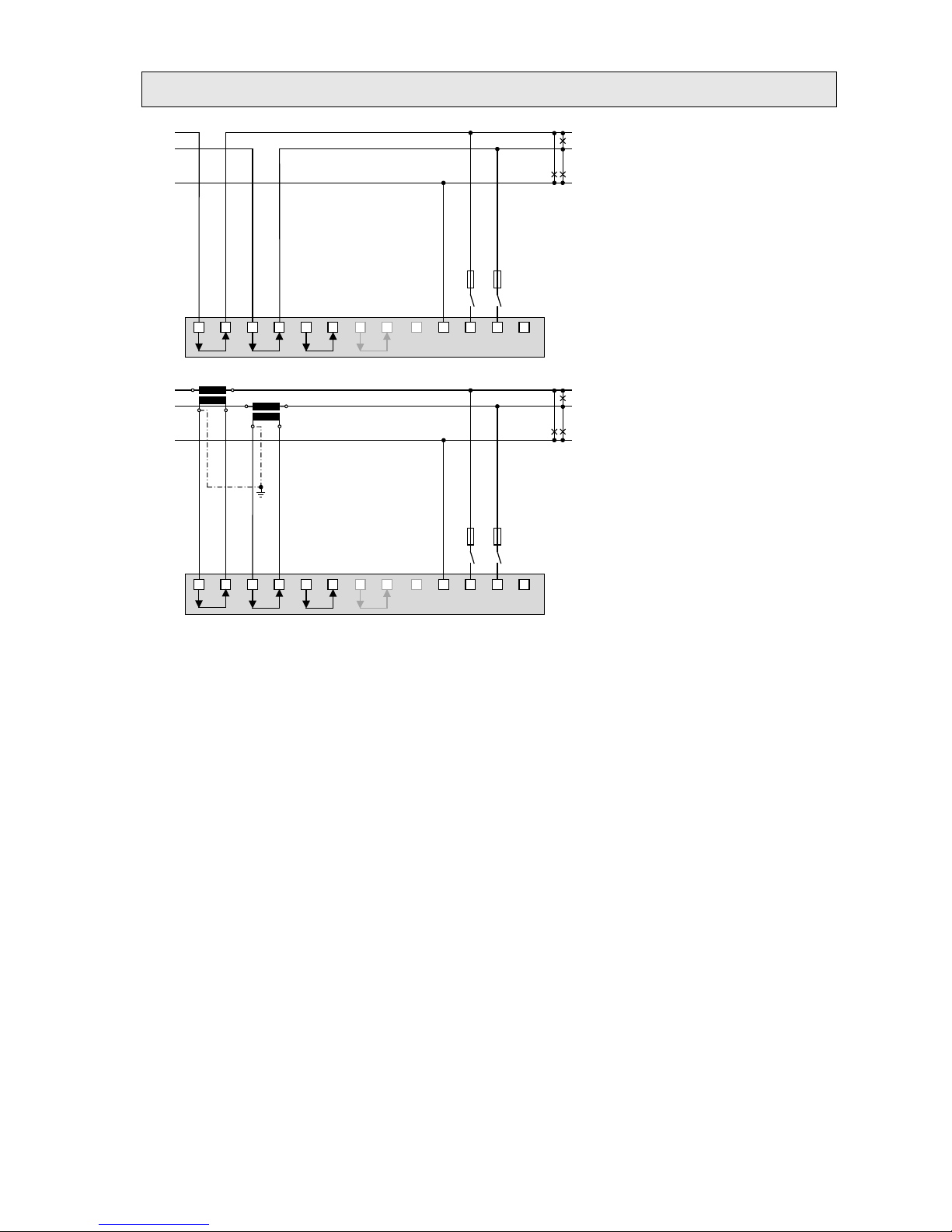
Earth fault monitoring in IT systems
Via the determination of the zero displacement voltage it's possible to detect a first earth fault in an
unearthed IT system. To do so, the device is configured for measurement in a 4-wire system with
unbalanced load and the neutral connector is connected to earth. In case of a single phase earth fault
there is a resulting zero displacement voltage of ULL/ √3. The alarming may be done e.g. by means of a
relay output.
Transformer, secondary side Load
Because in case of a fault the voltage triangle formed by the three phases does not change, the voltage
and current measurements as well as the system power values will still be measured and displayed
correctly. Also the meters carry on to work as expected.
The method is suited to detect a fault condition during normal operation. A declination of the isolation
resistance may not be detected this way. This should be measured during a periodical control of the
system using a mobile system.
Another possibility to analyze fau lt condit ions in a grid offers the method of the symmetrical components
as described in A3.

43/62 Device handbook SINEAX AM2000, 173 849, 04/2015
A2 Harmonic analysis
The harmolnic analysis is performed according IEC 61000-4-7 over 10 cycles at 50Hz resp. 12 cycles at
60Hz. If a measured quantity is available depends on the selected system.
Measurement
present
max
1L
2L
3Lb
3Lu
3Lu.A
4Lb
4Lu.O
4Lu
THD Voltage U1N/U
● ● √ √ √ √
√
THD Voltage U2N
● ● √ √ √
√
THD Voltage U3N
● ● √
√
THD Voltage U12
● ● √ √ √
THD Voltage U23
● ● √ √ √
THD Voltage U31
● ● √ √ √
THD Current I1/I
● ● √ √ √ √ √ √ √
√
THD Current I2
● ● √ √ √ √
√
THD Current I3
● ● √ √ √
√
TDD Current I1/I
● ● √ √ √ √ √ √ √
√
TDD Current I2
● ● √ √ √ √
√
TDD Current I3
● ● √ √ √
√
Harmonic contents 2nd...50th U1N/U
● ● √ √ √ √
√
Harmonic contents 2nd...50th U2N
● ● √ √
√
Harmonic contents 2nd...50th U3N
● ● √
√
Harmonic contents 2nd...50th U12
● ● √ √ √
Harmonic contents 2nd...50th U23
● ● √ √ √
Harmonic contents 2nd...50th U31
● ● √ √ √
Harmonic contents 2nd...50th I1/I
● ● √ √ √ √ √ √ √
√
Harmonic contents 2nd...50th I2
● ● √ √ √ √
√
Harmonic contents 2nd...50th I3
● ● √ √ √
√
√
Available via Modbus/RTU communication interface only
Harmonics
Harmonics are multiples of the fundamental resp. system frequency. They arise if non-linear loads, such
as RPM regulated drives, rectifiers, thyristor controlled systems or fluorescent lamps are present in the
power system. Thus undesired side effects occur, such as additional thermical stress to operational
resources or electrical mains, which lead to an advanced aging or even damage. Also the reliability of
sensitive loads can be affected and unexplainable disturbances may occur. In industrial networks the
image of the harmonics gives good information about the kind of loads connected. See also:
► Increase of reactive power due to harmonic currents
TDD (Total Demand Distortion)
The complete harmonic content of the currents is calculated additionally as Total Demand Distortion,
briefly TDD. This value is scaled to the rated current resp. rated power. Only this way it's possible to
estimate the influence of the current harmonics on the connected equipment correctly.
Maximum values
The maximum values of the harmonic analysis arise from the monitoring of THD and TDD. The maximum
values of individual harmonics are not monitored separately, but are stored if a maximum value of THD or
TDD is detected. The image of the maximum harmonics therefore always corresponds to the dedicated
THD resp. TDD.
The accuracy of the harmonic analysis strongly depends on the quality of the current and voltage
transformers possibly used. In the harmonics range transformers normally change both, the
amplitude and the phase of the signals to measure. It's valid: The higher the frequency of the
harmonic, the higher its damping resp. phase shift.

44/62 Device handbook SINEAX AM2000, 173 849, 04/2015
A3 System imbalance
Measured quantity
present
max
min
1L
2L
3Lb
3Lu
3Lu.A
4Lb
4Lu.O
4Lu
UR1: Positive sequence [V]
● √ √ √ √
UR2: Negative sequence [V]
● √ √ √ √
U0: Zero sequence [V]
● √
U: Imbalance UR2/UR1
● ● √ √ √ √
U: Imbalance U0/UR1
● ● √
IR1: Positive sequence [A]
● √ √ √
IR2: Negative sequence [A]
● √ √ √
I0: Zero sequence [A]
● √ √
I: Imbalance IR2/IR1
● ● √ √ √
I: Imbalance I0/IR1
● ● √ √
Imbalance in three-phase systems may occur due to single-phase loads, but also due to failures, such as
e.g. the blowing of a fuse, an earth fault, a phase failure or an isolation defect. Also harmonics of the 3rd,
9th, 15th, 21st etc. order, which add in the neutral wire, may lead to imbalance. Operating resources
dimensioned to rated values, such as three-phase generators, transformers or motors on load side, may
be excessively stressed by imbalance. So a shorter life cycle, a damage or failure due to thermical stress
can result. Therefore monitoring imbalance helps to reduce the costs for maintenance and extends the
undisturbed operating time of the used resources.
Imbalance or unbalanced load relays use different measurement principles. One of them is the approach
of the symmetrical components, the other one calculates the maximum deviation from the mean-value of
the three phase values. The results of these methods are not equal and don't have the same intention.
Both of these principles are implemented in the device.
Symmetrical components (acc. Fortescue)
The imbalance calculation method by means of the symmetrical components is ambitious and intensive to
calculate. The results may be used for disturbance analysis and for protection purposes in three-phase
systems. The real existing system is divided in symmetrical system parts: A positive sequence, a negative
sequence and (for systems with neutral conductor) a zero sequence system. The approach is easiest to
understand for rotating machines. The positive sequence represents a positive rotating field, the negative
sequence a negative (braking) rotating field with opposite sense of direction. Therefore the negative
sequence prevents that the machine can generate the full turning moment. For e.g. generators the
maximum permissible current imbalance is typically limited to a value of 8...12%.
Maximum deviation from the mean value
The calculation of the maximum deviation from the mean value of the phase currents resp. phase
voltages gives the information if a grid or substation is imbalanced loaded. The results are independent of
rated values and the present load situation. So a more symmetrical system can be aspired, e.g. by
changing loads from one phase to another.
Also failure detection is possible. The capacitors used in compensation systems are wear parts, which fail
quite often and then have to be replaced. When using three phase power capaci t or s all phases will be
compensated equally which leads to almost identical currents flowing through the capacitors, if the system
load is comparable. By monitoring the current imbalance it's then possible to estimate if a capacitor failure
is present.
The maximum deviations are calculated in the same steps as the instantaneous values and therefore are
arranged there (see A1
).

45/62 Device handbook SINEAX AM2000, 173 849, 04/2015
A4 Mean values and trend
Measured quantity
Present
Trend
max
min
History
Active power incoming 1s...60min. 1)
● ● ● ● 5
Active power outgoing 1s...60min. 1)
● ● ● ● 5
Reactive power incoming 1s...60min. 1)
● ● ● ● 5
Reactive power outgoing 1s...60min. 1)
● ● ● ● 5
Apparent power 1s...60min. 1)
● ● ● ● 5
Mean value quantity 1 1s...60min. 2)
● ● ● ● 1
….
Mean value quantity 12 1s...60min. 2)
● ● ● ● 1
1)
Interval time t1 2) Interval time t2
The device calculates automatically the mean values of all system power quantities. In addition up to 12
further mean value quantities can be freely selected.
Calculating the mean-values
The mean value calculation is performed via integration of the measured instanta neous va lues ov er a
configurable averaging inte r val. The interval time may be selected in the range from one second up to one
hour. Possible interim values are set the way that a multiple of it is equal to a minute or an hour. Mean
values of power quantities (interval time t1) and free quantities (interval time t2) may have different
averaging intervals.
Synchronization
For the synchronization of the averaging intervals the internal clock or an external signal via digital input
may be used. In case of an external synchronization the interval should be within the given range of one
second up to one hour. The synchronization is important for making e.g. the mean value of power
quantities on generating and demand side comparable.
Trend
The estimated final value (trend) of mean values is determined by weighted addition of measurements of
the past and the present interval. It serves for early detection of a possible exceeding of a given maximum
value. This can then be avoided, e.g. by switching off an active load.
History
For mean values of system powers the last 5 interval values may be displayed on the device or read via
interface. For configurable quantities the value of the last interval is provided via communication interface.
Bimetal current
This measured quantity serves for measuring the long-term effect of the current, e.g. for monitoring the
warming of a current-carrying line. To do so, an exponential function is used, similar to the charging curve
of a capacitor. The response time of the bimetal function can be freely selected, but normally it
corresponds to the interval for determining the power mean-values.
Measured quantity
Present
max
min
1L
2L
3Lb
3Lu
3Lu.A
4Lb
4Lu.O
4Lu
Bimetal current IB, 1...60min. 3)
● ● √ √ √
Bimetal current IB1, 1...60min. 3)
● ● √ √ √ √ √
Bimetal current IB2, 1...60min. 3)
● ● √ √ √ √ √
Bimetal current IB3, 1...60min. 3)
● ● √ √ √ √
3)
Interval time t3

46/62 Device handbook SINEAX AM2000, 173 849, 04/2015
A5 Meters
Measured quantity
1L
2L
3Lb
3Lu
3Lu.A
4Lb
4Lu.O
4Lu
Active energy incoming, high tariff
● ● ● ● ● ● ●
●
Active energy outgoing, high tariff
● ● ● ● ● ● ● ●
Reactive energy incoming, high tariff
● ● ● ● ● ● ● ●
Reactive energy outgoing, high tariff
● ● ● ● ● ● ● ●
Active energy incoming, low tariff
● ● ● ● ● ● ● ●
Active energy outgoing, low tariff
● ● ● ● ● ● ● ●
Reactive energy incoming, low tariff
● ● ● ● ● ● ● ●
Reactive energy outgoing, low tariff
● ● ● ● ● ● ● ●
User configured meter 1
Only basic quantities can be
selected which are supported in
the present system.
User configured meter 2
User configured meter 3
User configured meter 4
User configured meter 5
User configured meter 6
User configured meter 7
User configured meter 8
User configured meter 9
User configured meter 10
User configured meter 11
User configured meter 12
Standard meters
The meters for active and reactive energy of the system are always active.
User configured meters
To each of these meters the user can freely assign a basic quantity and a tariff. For application with short
measurement time, e.g. energy consumption of a working day or shift, the resoluti on can be ada pted .

47/62 Device handbook SINEAX AM2000, 173 849, 04/2015
B Display matrices
B0 Used abbreviations for the measurements
Instantaneous values
Name Measurement identification Unit Description
U U
TRMS
V
Voltage system
U1N U
1N TRMS
V
Voltage between phase L1 and neutral
U2N U
2N TRMS
V
Voltage between phase L2 and neutral
U3N U
3N TRMS
V
Voltage between phase L3 and neutral
U12 U
12 TRMS
V
Voltage between phases L1 and L2
U23 U
23 TRMS
V
Voltage between phases L2 and L3
U31 U
31 TRMS
V
Voltage between phases L3 and L1
UNE U
NE TRMS
V
Zero displacement voltage 4-wire systems
I I
TRMS
A
Current system
I1 I
1 TRMS
A
Current phase L1
I2 I
2 TRMS
A
Current phase L2
I3 I
3 TRMS
A
Current phase L3
IN I
N TRMS
A
Neutral current
P P
TRMS
W
Active power system (P=P1+P2+P3)
P1 P
1 TRMS
W
Active power phase L1
P2 P
2 TRMS
W
Active power phase L2
P3 P
3 TRMS
W
Active power phase L3
Q Q
TRMS
var
Reactive power system (Q=Q1+Q2+Q3)
Q1 Q
1 TRMS
var
Reactive power phase L1
Q2 Q
2 TRMS
var
Reactive power phase L2
Q3 Q
3 TRMS
var
Reactive power phase L3
S S
TRMS
VA
Apparent power system
S1 S
1 TRMS
VA
Apparent power phase L1
S2 S
2 TRMS
VA
Apparent power phase L2
S3 S
3 TRMS
VA
Apparent power phase L3
F F
TRMS
Hz
System frequency
PF PF
TRMS
Active power factor P/S
PF1 PF
1 TRMS
Active power factor P1/S1
PF2 PF
2 TRMS
Active power factor P2/S2
PF3 PF
3 TRMS
Active power factor P3/S3
QF QF
TRMS
Reactive power factor Q / S
QF1 QF
1 TRMS
Reactive power factor Q1 / S1
QF2 QF
2 TRMS
Reactive power factor Q2 / S2
QF3 QF
3 TRMS
Reactive power factor Q3 / S3
LF LF
TRMS
Load factor system
LF1 LF
1 TRMS
Load factor phase L1
LF2 LF
2 TRMS
Load factor phase L2
LF3 LF
3 TRMS
Load factor phase L3
UR1
U
pos SEQ
V
Positive sequence voltage
UR2
U
neg SEQ
V
Negative sequence voltage
U0
U
zero SEQ
V
Zero sequence voltage
IR1
I
pos SEQ
A
Positive sequence current
IR2
I
neg SEQ
A
Negative sequence current
I0
I
zero SEQ
A
Zero sequence current
UR2R1
U
neg/pos UNB
%
Unbalance factor voltage UR2/UR1
IR2R1 I
neg/pos UNB
% Unbalance factor current IR2/IR1
U0R1 U
zero/pos UNB
% Unbalance factor voltage U0/UR1
I0R1 I
zero/pos UNB
% Unbalance factor current I0/IR1

48/62 Device handbook SINEAX AM2000, 173 849, 04/2015
Minimum and maximum of instantaneous values
Name Measurement identification Unit Description
U_MM U
TRMS
V
Minimum and maximum value of U
U1N_MM U
1N
TRMS
V
Minimum and maximum value of U1N
U2N_MM U
2N
TRMS
V
Minimum and maximum value of U2N
U3N_MM U
3N
TRMS
V
Minimum and maximum value of U3N
U12_MM U
12
TRMS
V
Minimum and maximum value of U12
U23_MM U
23
TRMS
V
Minimum and maximum value of U23
U31_MM U
31
TRMS
V
Minimum and maximum value of U31
I_MAX I
TRMS
A
Maximum value of I
I1_MAX I
1
TRMS
A
Maximum value of I1
I2_MAX I
2
TRMS
A
Maximum value of I2
I3_MAX I
3
TRMS
A
Maximum value of I3
IN_MAX I
N
TRMS
A
Maximum value of IN
P_MAX P
TRMS
W
Maximum value of P
P1_MAX P
1
TRMS
W
Maximum value of P1
P2_MAX P
2
TRMS
W
Maximum value of P2
P3_MAX P
3
TRMS
W
Maximum value of P3
Q_MAX Q
TRMS
var
Maximum value of Q
Q1_MAX Q
1
TRMS
var
Maximum value of Q1
Q2_MAX Q
2
TRMS
var
Maximum value of Q2
Q3_MAX Q
3
TRMS
var
Maximum value of Q3
S_MAX S
TRMS
VA
Maximum value of S
S1_MAX S
1
TRMS
VA
Maximum value of S1
S2_MAX S
2
TRMS
VA
Maximum value of S2
S3_MAX S
3
TRMS
VA
Maximum value of S3
F_MM F
TRMS
Hz
Minimum and maximum value of F
UR21_MAX
U
neg/pos
UNB
%
Maximum value of UR2/UR1
IR21_MAX
I
neg/pos
UNB
%
Maximum value of IR2/IR1
THD_U_MAX
U
THD
%
Max. Total Harmonic Distortion of U
THD_U1N_MAX
U
1N
THD
%
Max. Total Harmonic Distortion of U1N
THD_U2N_MAX
U
2N
THD
%
Max. Total Harmonic Distortion of U2N
THD_U3N_MAX
U
3N
THD
%
Max. Total Harmonic Distortion of U3N
THD_U12_MAX U
12
THD
% Max. Total Harmonic Distortion of U12
THD_U23_MAX U
23
THD
% Max. Total Harmonic Distortion of U23
THD_U31_MAX U
31
THD
% Max. Total Harmonic Distortion of U31
TDD_I_MAX I
TDD
% Max. Total Demand Distortion of I
TDD_I1_MAX
I
1
TDD
%
Max. Total Demand Distortion of I1
TDD_I2_MAX
I
2
TDD
%
Max. Total Demand Distortion of I2
TDD_I3_MAX
I
3
TDD
%
Max. Total Demand Distortion of I3
TS: Timestamp of occurrence, e.g. 2014/09/17 11:12:03
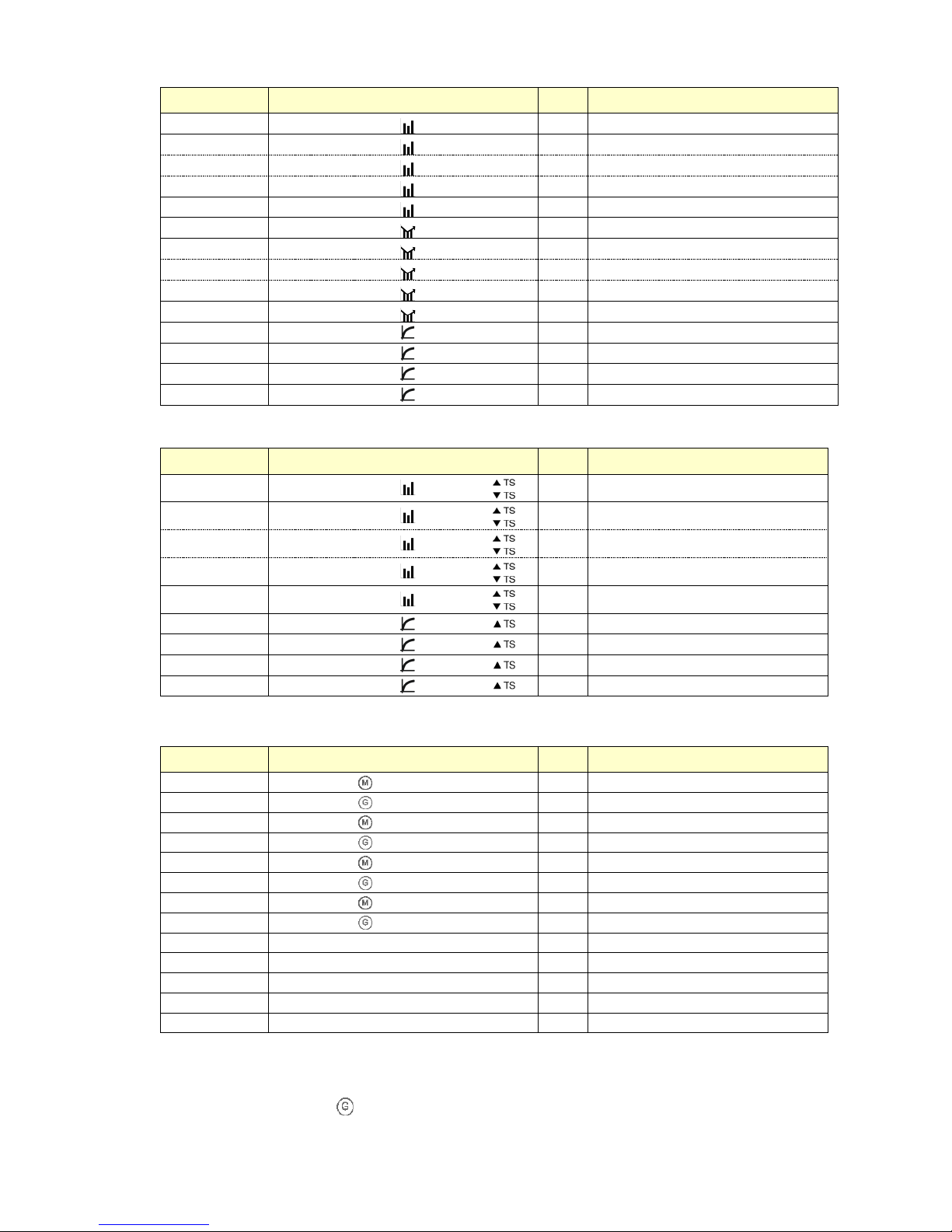
49/62 Device handbook SINEAX AM2000, 173 849, 04/2015
Mean-values, trend and bimetal current
Name Measurement identification Unit Description
M1
(m) (p) (q)
(t2)
(mu)
Mean-value 1
M2
(m) (p) (q)
(t2)
(mu)
Mean-value 2
….
(m) (p) (q)
(t2)
(mu)
….
M11
(m) (p) (q)
(t2)
(mu)
Mean-value 11
M12
(m) (p) (q)
(t2)
(mu)
Mean-value 12
TR_M1
(m) (p) (q)
(t2)
(mu)
Trend mean-value 1
TR_M2
(m) (p) (q)
(t2)
(mu)
Trend mean-value 2
….
(m) (p) (q)
(t2)
(mu)
….
TR_M11
(m) (p) (q)
(t2)
(mu)
Trend mean-value 11
TR_M12
(m) (p) (q)
(t2)
(mu)
Trend mean-value 12
IB
IB
(t3)
A
Bimetal current, system
IB1
IB 1
(t3)
A
Bimetal current, phase L1
IB2
IB 2
(t3)
A
Bimetal current, phase L2
IB3
IB 3
(t3)
A
Bimetal current, phase L3
Minimum and maximum of mean-values and bimetal-current
Name Measurement identification Unit Description
M1_MM
(m) (p) (q)
(t2)
..
Min/Max mean-value 1
M2_MM
(m) (p) (q)
(t2)
..
Min/Max mean-value 2
….
(m) (p) (q)
(t2)
..
….
M11_MM
(m) (p) (q)
(t2)
..
Min/Max mean-value 11
M12_MM
(m) (p) (q)
(t2)
..
Min/Max mean-value 12
IB_MAX
IB
(t3)
A
Maximum bimetal current, system
IB1_MAX
IB 1
(t3)
A
Maximum Bimetal current, phase L1
IB2_MAX
IB 2
(t3)
A
Maximum Bimetal current, phase L2
IB3_MAX
IB 3
(t3)
A
Maximum Bimetal current, phase L3
Meters
Name Measurement identification Unit Description
ΣPIN_HT P
ΣHT
Wh Meter P incoming high tariff
ΣPOUT_HT P
ΣHT
Wh Meter P outgoing high tariff
ΣQIN_HT Q
ΣHT
varh Meter Q incoming high tariff
ΣQOUT_HT Q
ΣHT
varh Meter Q outgoing high tariff
ΣPIN_NT P
ΣLT
Wh Meter P incoming low tariff
ΣPOUT_NT P
ΣLT
Wh Meter P outgoing low tariff
ΣQIN_NT Q
ΣLT
varh Meter Q incoming low tariff
ΣQOUT_NT Q
ΣLT
varh Meter Q outgoing low tariff
ΣMETER1 (m) (p) (q) Σ(T)
(mu)
User meter 1, Tarif HT oder NT
ΣMETER2 (m) (p) (q) Σ(T)
(mu)
User meter 2, Tarif HT oder NT
….. (m) (p) (q) Σ(T)
(mu)
…..
ΣMETER11 (m) (p) (q) Σ(T)
(mu) Us er m eter 11, Tarif HT oder NT
ΣMETER12 (m) (p) (q) Σ(T)
(mu) Us er m eter 12, Tarif HT oder NT
(m): Short description of basic quantity, e.g. „P“
(p): Phase reference of the selected quantity, e.g. „1 “
(q): Quadrant information, e.g. „ “ (outgoing)
(t2), (t3): Averaging interval, e.g. „5s“, or „15min“
(T): Associated tariff, e.g. „HT" or „LT“
(mu): Unit of basic quantity

50/62 Device handbook SINEAX AM2000, 173 849, 04/2015
Graphical measurement displays
Name Presentation Description
Px_TRIANGLE
Graphic of the power triangle consisting of:
• Active, reactive and apparent power Px,Qx,Sx
• Distortion reactive power Dx
• Fundamental reactive power Qx(H1)
• cos(φ) of fundamental
• Active power factor PFx
PF_MIN
Graphic: Minimum active power factor PF in all 4 quadrants
Cφ_MIN (as PF_MIN) Graphic: Minimum cos(φ) in all 4 quadrants
MT_S
Graphic mean-value S: Trend, last 5 interval val ues, minimum and
maximum
MT_PIN (as MT_S)
Graphic mean-value P incoming: Trend, last 5 interval values, minimum
and maximum
MT_POUT (as MT_S)
Graphic mean-value P outgoing: Trend, last 5 interval values, minimum
and maximum
MT_QIN (as MT_S)
Graphic mean-value Q incoming: Trend, last 5 interval values, minimum
and maximum
MT_QOUT (as MT_S)
Graphic mean-value Q outgoing: Trend, last 5 interval values, minimum
and maximum
HO_UX
Graphic: Odd harmonics 3rd up to 49th + Total Harmonic Distortion of all
voltages
HO_IX (as HO_UX)
Graphic: Odd harmonics 3
rd
up to 49th + Total Harmonic Distortion of all
currents
HE_UX (as HO_UX)
Graphic: Even harmonics 2
nd
up to 50th + Total Harmonic Distortion of all
voltages
HE_IX (as HO_UX)
Graphic: Even harmonics 2
nd
up to 50th + Total Harmonic Distortion of all
currents
HO_UX_MAX (as HO_UX)
Graphic: Maximum values odd harmonics 3rd up to 49th + Total Harmonic
Distortion of all voltages
HO_IX_MAX (as HO_UX)
Graphic: Maximum values odd harmonics 3rd up to 49th + Total Harmonic
Distortion of all currents
HE_UX_MAX (as HO_UX)
Graphic: Maximum values even harmonics 2nd up to 50th + Total
Harmonic Distortion of all voltages
HE_IX_MAX (as HO_UX)
Graphic: Maximum values even harmonics 2nd up to 50th + Total
Harmonic Distortion of all currents
PHASOR
Graphic: All current and voltage phasors with present load sitution

51/62 Device handbook SINEAX AM2000, 173 849, 04/2015
B1 Display matrices for single phase system
Display menu Corresponding matrix
U
U_MM
I I_MAX
P P_MAX
F F_MM
P P_MAX
Q Q_MAX
S S_MAX
PF
P_TRIANGLE
PF_MIN
Cφ_MIN
ΣPIN_HT
ΣPIN_LT
ΣQIN_HT
ΣQIN_LT
ΣPOUT_HT
ΣPOUT_LT
ΣQOUT_HT
ΣQOUT_LT
ΣMETER1
ΣMETER2
ΣMETER3
ΣMETER4
ΣMETER5
ΣMETER6
ΣMETER7
ΣMETER8
ΣMETER9
ΣMETER10
ΣMETER11
ΣMETER12
MT_PIN
MT_POUT
MT_QIN
MT_QOUT
MT_S
TR_M1 / M1
TR_M5 / M5
TR_M9 / M9
M1_MM
M1_MM
M1_MM
TR_M2 / M2
TR_M6 / M6
TR_M10 / M10
M2_MM
M2_MM
M2_MM
TR_M3 / M3
TR_M7 / M7
TR_M11 / M11
M3_MM
M3_MM
M3_MM
TR_M4 / M4
TR_M8 / M8
TR_M12 / M12
M4_MM
M4_MM
M4_MM
IB
IB_MAX

52/62 Device handbook SINEAX AM2000, 173 849, 04/2015
B2 Display matrices for split-phase (two-phase) systems
Display menu Corresponding matrix
U1N
U1N_MM
U2N
U2N_MM
U
U_MM
F
F_MM
I1
I2
I1_MAX
I2_MAX
P
P1
P_MAX / P1_MAX
Q P2
Q_MAX / P2_MAX
S Q1
S_MAX / Q1_MAX
PF
Q2
- / Q2_MAX
P_TRIANGLE
P1_TRIANGLE
P2_TRIANGLE
PF_MIN
Cφ_MIN
ΣPIN_HT
ΣPIN_LT
ΣQIN_HT
ΣQIN_LT
ΣPOUT_HT
ΣPOUT_LT
ΣQOUT_HT
ΣQOUT_LT
ΣMETER1
ΣMETER2
ΣMETER3
ΣMETER4
ΣMETER5
ΣMETER6
ΣMETER7
ΣMETER8
ΣMETER9
ΣMETER10
ΣMETER11
ΣMETER12
MT_PIN
MT_POUT
MT_QIN
MT_QOUT
MT_S
TR_M1 / M1
TR_M5 / M5
TR_M9 / M9
M1_MM
M1_MM
M1_MM
TR_M2 / M2
TR_M6 / M6
TR_M10 / M10
M2_MM
M2_MM
M2_MM
TR_M3 / M3
TR_M7 / M7
TR_M11 / M11
M3_MM
M3_MM
M3_MM
TR_M4 / M4
TR_M8 / M8
TR_M12 / M12
M4_MM
M4_MM
M4_MM
IB1
IB2
IB1_MAX
IB2_MAX

53/62 Device handbook SINEAX AM2000, 173 849, 04/2015
B3 Display matrices for 3-wire system, balanced load
Display menu Corresponding matrix
U12
U12_MM
UR1 U23
U23_MM
UR2 U31
U31_MM
UR2R1
F
F_MM
UR21_MAX
I
I_MAX
P
P_MAX
Q Q_MAX
S S_MAX
PF
P_TRIANGLE
PF_MIN
Cφ_MIN
ΣPIN_HT
ΣPIN_LT
ΣQIN_HT
ΣQIN_LT
ΣPOUT_HT
ΣPOUT_LT
ΣQOUT_HT
ΣQOUT_LT
ΣMETER1
ΣMETER2
ΣMETER3
ΣMETER4
ΣMETER5
ΣMETER6
ΣMETER7
ΣMETER8
ΣMETER9
ΣMETER10
ΣMETER11
ΣMETER12
MT_PIN
MT_POUT
MT_QIN
MT_QOUT
MT_S
TR_M1 / M1
TR_M5 / M5
TR_M9 / M9
M1_MM
M1_MM
M1_MM
TR_M2 / M2
TR_M6 / M6
TR_M10 / M10
M2_MM
M2_MM
M2_MM
TR_M3 / M3
TR_M7 / M7
TR_M11 / M11
M3_MM
M3_MM
M3_MM
TR_M4 / M4
TR_M8 / M8
TR_M12 / M12
M4_MM
M4_MM
M4_MM
IB
IB_MAX

54/62 Device handbook SINEAX AM2000, 173 849, 04/2015
B4 Display matrices for 3-wire systems, unbalanced load
Display menu Corresponding matrix
U12
U12_MM
UR1 U23
U23_MM
UR2 U31
U31_MM
UR2R1
F
F_MM
UR21_MAX
I1
I1_MAX
IR1
I2
I2_MAX
IR2
I3
I3_MAX
IR2R1
IR21_MAX
P
P_MAX
Q Q_MAX
S S_MAX
PF
P_TRIANGLE
PF_MIN
Cφ_MIN
ΣPIN_HT
ΣPIN_LT
ΣQIN_HT
ΣQIN_LT
ΣPOUT_HT
ΣPOUT_LT
ΣQOUT_HT
ΣQOUT_LT
ΣMETER1
ΣMETER2
ΣMETER3
ΣMETER4
ΣMETER5
ΣMETER6
ΣMETER7
ΣMETER8
ΣMETER9
ΣMETER10
ΣMETER11
ΣMETER12
MT_PIN
MT_POUT
MT_QIN
MT_QOUT
MT_S
TR_M1 / M1
TR_M5 / M5
TR_M9 / M9
M1_MM
M1_MM
M1_MM
TR_M2 / M2
TR_M6 / M6
TR_M10 / M10
M2_MM
M2_MM
M2_MM
TR_M3 / M3
TR_M7 / M7
TR_M11 / M11
M3_MM
M3_MM
M3_MM
TR_M4 / M4
TR_M8 / M8
TR_M12 / M12
M4_MM
M4_MM
M4_MM
IB1
IB1_MAX
IB2
IB2_MAX
IB3
IB3_MAX

55/62 Device handbook SINEAX AM2000, 173 849, 04/2015
B5 Display matrices for 3-wire systems, unbalanced load, Aron
Display menu Corresponding matrix
U12
U12_MM
UR1 U23
U23_MM
UR2 U31
U31_MM
UR2R1
F
F_MM
UR21_MAX
I1
I1_MAX
IR1
I2
I2_MAX
IR2
I3
I3_MAX
IR2R1
IR21_MAX
P
P_MAX
Q Q_MAX
S S_MAX
PF
P_TRIANGLE
PF_MIN
Cφ_MIN
ΣPIN_HT
ΣPIN_LT
ΣQIN_HT
ΣQIN_LT
ΣPOUT_HT
ΣPOUT_LT
ΣQOUT_HT
ΣQOUT_LT
ΣMETER1
ΣMETER2
ΣMETER3
ΣMETER4
ΣMETER5
ΣMETER6
ΣMETER7
ΣMETER8
ΣMETER9
ΣMETER10
ΣMETER11
ΣMETER12
MT_PIN
MT_POUT
MT_QIN
MT_QOUT
MT_S
TR_M1 / M1
TR_M5 / M5
TR_M9 / M9
M1_MM
M1_MM
M1_MM
TR_M2 / M2
TR_M6 / M6
TR_M10 / M10
M2_MM
M2_MM
M2_MM
TR_M3 / M3
TR_M7 / M7
TR_M11 / M11
M3_MM
M3_MM
M3_MM
TR_M4 / M4
TR_M8 / M8
TR_M12 / M12
M4_MM
M4_MM
M4_MM
IB1
IB1_MAX
IB2
IB2_MAX
IB3
IB3_MAX

56/62 Device handbook SINEAX AM2000, 173 849, 04/2015
B6 Display matrices for 4-wire system, balanced load
Display menu Corresponding matrix
U
U_MM
I
I_MAX
P
P_MAX
F
F_MM
P
P_MAX
Q
Q_MAX
S
S_MAX
PF
P_TRIANGLE
PF_MIN
Cφ_MIN
ΣPIN_HT
ΣPIN_LT
ΣQIN_HT
ΣQIN_LT
ΣPOUT_HT
ΣPOUT_LT
ΣQOUT_HT
ΣQOUT_LT
ΣMETER1
ΣMETER2
ΣMETER3
ΣMETER4
ΣMETER5
ΣMETER6
ΣMETER7
ΣMETER8
ΣMETER9
ΣMETER10
ΣMETER11
ΣMETER12
MT_PIN
MT_POUT
MT_QIN
MT_QOUT
MT_S
TR_M1 / M1
TR_M5 / M5
TR_M9 / M9
M1_MM
M1_MM
M1_MM
TR_M2 / M2
TR_M6 / M6
TR_M10 / M10
M2_MM
M2_MM
M2_MM
TR_M3 / M3
TR_M7 / M7
TR_M11 / M11
M3_MM
M3_MM
M3_MM
TR_M4 / M4
TR_M8 / M8
TR_M12 / M12
M4_MM
M4_MM
M4_MM
IB
IB_MAX

57/62 Device handbook SINEAX AM2000, 173 849, 04/2015
B7 Display matrices for 4-wire systems, unbalanced load
Display menu Corresponding matrix
U1N
U12
U1N_MM / U12_MM
UR1 U2N
U23
U2N_MM / U23_MM
UR2 U3N
U31
U3N_MM / U31_MM
U0 UNE F F_MM / UR2_MM
UNB_UR2_UR1
I1
I1_MAX
IR1 I2
I2_MAX
IR2 I3
I3_MAX
I0 IN
IN_MAX
UNB_IR2_IR1
P P1
Q1
S1
P1_MAX
Q1_MAX
S1_MAX
Q
P2
Q2
S2
P2_MAX
Q2_MAX
S2_MAX
S
P3
Q3
S3
P3_MAX
Q3_MAX
S3_MAX
PF P Q S P_MAX
Q_MAX
S_MAX
P_TRIANGLE
P1_TRIANGLE
P2_TRIANGLE
P3_TRIANGLE
PF_MIN
Cφ_MIN
ΣPIN_HT
ΣPIN_LT
ΣQIN_HT
ΣQIN_LT
ΣPOUT_HT
ΣPOUT_LT
ΣQOUT_HT
ΣQOUT_LT
ΣMETER1
ΣMETER2
ΣMETER3
ΣMETER4
ΣMETER5
ΣMETER6
ΣMETER7
ΣMETER8
ΣMETER9
ΣMETER10
ΣMETER11
ΣMETER12
MT_PIN
MT_POUT
MT_QIN
MT_QOUT
MT_S
TR_M1 / M1
TR_M5 / M5
TR_M9 / M9
M1_MM
M1_MM
M1_MM
TR_M2 / M2
TR_M6 / M6
TR_M10 / M10
M2_MM
M2_MM
M2_MM
TR_M3 / M3
TR_M7 / M7
TR_M11 / M11
M3_MM
M3_MM
M3_MM
TR_M4 / M4
TR_M8 / M8
TR_M12 / M12
M4_MM
M4_MM
M4_MM
IB1
IB1_MAX
IB2
IB2_MAX
IB3
IB3_MAX

58/62 Device handbook SINEAX AM2000, 173 849, 04/2015
B8 Display matrices for 4-wire system, unbalanced load, Open-Y
Display menu Corresponding matrix
U1N
U12
U1N_MM / U12_MM
U2N
U23
U2N_MM / U23_MM
U3N
U31
U3N_MM / U31_MM
F F
F_MM / --
I1
I1_MAX
IR1 I2
I2_MAX
IR2 I3
I3_MAX
I0 IN
IN_MAX
UNB_IR2_IR1
P P1
Q1
S1
P1_MAX
Q1_MAX
S1_MAX
Q
P2
Q2
S2
P2_MAX
Q2_MAX
S2_MAX
S
P3
Q3
S3
P3_MAX
Q3_MAX
S3_MAX
PF P Q S P_MAX
Q_MAX
S_MAX
P_TRIANGLE
P1_TRIANGLE
P2_TRIANGLE
P3_TRIANGLE
PF_MIN
Cφ_MIN
ΣPIN_HT
ΣPIN_LT
ΣQIN_HT
ΣQIN_LT
ΣPOUT_HT
ΣPOUT_LT
ΣQOUT_HT
ΣQOUT_LT
ΣMETER1
ΣMETER2
ΣMETER3
ΣMETER4
ΣMETER5
ΣMETER6
ΣMETER7
ΣMETER8
ΣMETER9
ΣMETER10
ΣMETER11
ΣMETER12
MT_PIN
MT_POUT
MT_QIN
MT_QOUT
MT_S
TR_M1 / M1
TR_M5 / M5
TR_M9 / M9
M1_MM
M1_MM
M1_MM
TR_M2 / M2
TR_M6 / M6
TR_M10 / M10
M2_MM
M2_MM
M2_MM
TR_M3 / M3
TR_M7 / M7
TR_M11 / M11
M3_MM
M3_MM
M3_MM
TR_M4 / M4
TR_M8 / M8
TR_M12 / M12
M4_MM
M4_MM
M4_MM
IB1
IB1_MAX
IB2
IB2_MAX
IB3
IB3_MAX

59/62 Device handbook SINEAX AM2000, 173 849, 04/2015
C Logic funct ions
The principal function of the logical gates is given in the following table, for simplicity shown for gates with
two inputs only.
function symbol
older symbols
truth table plain text
ANSI 91-1984
DIN 40700 (alt)
AND
A B Y 0 0 0 0 1 0
1 0 0
1 1 1
Function is true if all input
conditions are fulfilled
NAND
A B Y 0 0
1
0 1 1
1 0 1 1 1
0
Function is true if at least
one of the input
conditions is not fulfilled
OR
A B Y
0 0 0
0 1 1 1 0 1 1 1 1
Function is true if at least
one of the input
conditions is fulfilled
NOR
A B Y
0 0 1 0 1 0 1 0 0 1 1
0
Function is true if none of
the input conditions is
fulfilled
Using DIRECT or INVERT the input is directly connected to the output of a monitoring function, without
need for a logical combination. Only one input is allowed for these functions.
DIRECT
A
Y
A Y 0 0 1
1
The monitoring function is reduced to one input only. The state of
the output corresponds to the input.
INVERT
=1
A
Y
A Y 0 1 1
0
The monitoring function is reduced to one input only. The state of
the output corresponds to the inverted input.

60/62 Device handbook SINEAX AM2000, 173 849, 04/2015
D Declaration of conformity
D1 CE conformity

61/62 Device handbook SINEAX AM2000, 173 849, 04/2015
D2 FCC statement
The following statement applies to the products covered in this manual, unless otherwise specified herein.
The statement for other products will appear in the accompanying documentation.
NOTE: This equipment has been tested and found to comply with the limits for a Class A digital device,
pursuant to Part 15 of the FCC Rules and meets all requirements of the Canadian Interference-Causing
Equipment Standard ICES-003 for digital apparatus. These limits are designed to provide reasonable
protection against harmful interference in a residential installation. This equipment generates, uses, and
can radiate radio frequency energy and, if not installed and used in accordance with the instructions, may
cause harmful interference to radio communications. However, there is no guarantee that interference will
not occur in a particular installation. If this equipment does cause harmful interference to radio or
television reception, which can be determined by turning the equipment off and on, the user is
encouraged to try to correct the interference by one or more of the following measures:
• Reorient or relocate the receiving antenna.
• Increase the separation between the equipment and receiver.
• Connect the equipment into an outlet on a circuit different from that to which the receiver is connected.
• Consult the dealer or an experienced radio/T.V. technician for help.
Camille Bauer AG is not responsible for any radio television interference caused by unauthorized
modifications of this equipment or the substitution or attachment of connecting cables and equipment
other than those specified by Camille Bauer AG. The correction of interference caused by such
unauthorized modification, substitution or attachment will be the responsibility of the user.

62/62 Device handbook SINEAX AM2000, 173 849, 04/2015
INDEX
C
Commissioning ..................................................... 22
Configuration
menu ................................................................. 29
D
Declaration of conformity ...................................... 60
Demounting ............................................................. 7
Device overview ...................................................... 6
Dimensional drawing ............................................ 38
Display matrices.................................................... 47
Driving a counter mechanism ............................... 20
E
Electrical connections
analog outputs .................................................. 20
Aron connection ................................................ 15
cross sections ..................................................... 9
digital input ....................................................... 19
digital output ..................................................... 20
I/O extensions ..................................................... 9
inputs ................................................................ 10
Modbus interface .............................................. 21
Open-Y ............................................................. 17
power supply .................................................... 19
relays ................................................................ 19
split phase ........................................................ 18
I
Installation check .................................................. 23
L
Logic components
AND .................................................................. 59
DIRECT ............................................................ 59
INVERT ............................................................ 59
NAND................................................................ 59
NOR .................................................................. 59
OR .................................................................... 59
M
Measured quantities ............................................. 39
Basic measurements ....................................... 39
Bimetal current ................................................. 45
earth fault monitoring ....................................... 42
harmonic analysis ............................................ 43
Load factors ..................................................... 41
mean values and trend .................................... 45
meters .............................................................. 46
system imbalance ............................................ 44
zero displacement voltage ............................... 42
Measurement displays ......................................... 25
Measurements
reset ................................................................. 29
Mechanical mounting ............................................. 7
Menu operation .................................................... 24
Mounting ................................................................ 7
O
Operating elements .............................................. 24
R
Reactive power .................................................... 41
Resetting measurements ..................................... 29
S
Safety notes ........................................................... 6
Scope of supply ..................................................... 5
Service and maintenance .................................... 31
Symbols ............................................................... 26
Symmetrical components..................................... 44
T
Technical data ...................................................... 32
Z
Zero suppression ................................................. 33
 Loading...