

Page 1

D I S T R I B U T E D V A L V E S
Installation, Operation and Maintenance Manual
®
WKM MODEL MB
®
DYNACENTRIC HIGH PERFORMANCE
BUTTERFLY VALVE
®
WKM
IOM-WKM-HPBV-MBInstallation, Operation and Maintenance Manual
Page 2

D I S T R I B U T E D V A L V E S
TABLE OF CONTENTS
WKM DYNACENTRIC MB HIGH PERFORMANCE
BUTTERFLY VALVE
Bill of Materials .......................................................... 1
Catalog Number Information ..................................... 3
Nameplate Information .............................................. 3
Scope ........................................................................ 4
Storage ...................................................................... 4
Installation ................................................................. 4
End-of-Line Service ........................................ 5
Disc/Pipe Clearance ....................................... 5
Gaskets ......................................................... 6
Flange Bolt and Stud Size .............................. 6
Procedure ....................................................... 7
Operation .................................................................. 8
Routine Maintenance ................................................ 9
Trouble Shooting ....................................................... 9
© Cameron’s Valves & Measurement Group Rev. 2 04/09 IOM-WKM-HPBV-MB
IOM-WKM-HPBV-MBInstallation, Operation and Maintenance Manual
Page 3

Bill of Materials
11
9
10
D I S T R I B U T E D V A L V E S
13
21
23
20
7
8
1
7
4
19
16
(Wafer body with slip-in seat
retainer shown.)
17
14 22 3 2
Figure 1 - Cameron Valves' WKM 2 1/2" - 24" Class 150 and 300 DynaCentric Wafer Valve Components.
ITEM DESCRIPTION
1. Body
2. Seat Retainer
3. Seat Retainer O-ring
3a. Seat Retainer Screw
4. Stem/Disc Spring
7. Stem Bearing
8. Nameplate
9. Gland Retainer
10. Gland Retainer Stud
11. Gland Retainer Nut
13. Stem
14. Disc
15. Lower Stem*
ITEM DESCRIPTION
16. Stem Pins
17. Disc Spacer
18. Key (8" - 12" Only)
19. Stem Retainer Pins
20. Packing Spacer
21. Gland Ring
22. Seat
23. Packing Set
25. Bottom Cover*
26. Bottom Cover Gasket*
27. Bottom Cover Screw*
*(10" 300 and larger and 12” 150 and larger)
1
IOM-WKM-HPBV-MBInstallation, Operation and Maintenance Manual
Page 4

Bill of Materials
11
9
10
21
23
20
7
8
13
19
16
D I S T R I B U T E D V A L V E S
(Lug body with bolt-in seat
retainer shown.)
17
14 22 32
1
7
4
Figure 2 - Cameron Valves' WKM 2 1/2" - 36” Class 150 and 300 DynaCentric Lug Valve Components.
Detail of Bottom Cap
(10" 300 and larger and 12” 150 and larger)
26
25, 15
27
2
IOM-WKM-HPBV-MBInstallation, Operation and Maintenance Manual
Page 5
D I S T R I B U T E D V A L V E S
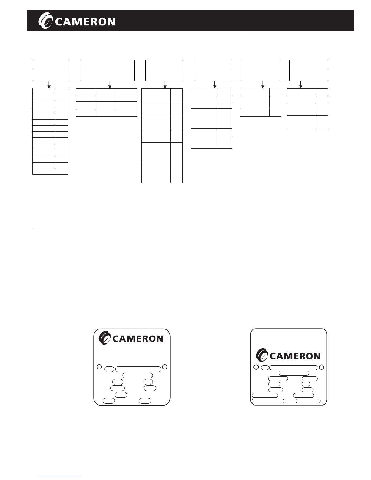
Catalog Number Information
XX - B5XXX - XX - XXX - XX - XX
Size Body Trim Seal Packing Actuation
Inches Group Group Group Gr ou p
1 1/2" 02
3" 03
4" 04
5" 05
6" 06
8" 08
10" 10
12" 12
14" 14
16" 16
18" 18
20" 20
24" 24
36" 36
Class Material Style
1=150 1-CS 0-Wafer
3=300 2=SS
3=CS2
1
2=Wafer
3=Lug
SS Disc 02
17-4 Stem
3
SS Disc 03
3
Ni-Cr
Ni-Cu Disc 04
and Stem
SS Disc 05
316SS Stem
SS Disc
HF-6 O/L 06
17-4 Stem
SS Disc
HF-6O/L
NI-Cr Stem
4
Stem
5
4
TFE S01
RTFE S02
SS/RTFE F02
4
Ni-Cr
(UNS 6625) F03
/RTFE
2
6
316SS M01
4
Ni-Cr
(UNS 6625)
M03
TFE VEE 11
High Temp 13
Galvenized
Grafoil 14
Note: Valves with optional materials of construction
6
07
are available on application.
1
Controlled hardness carbon steel (H S Service).
2
Valves equipped with 316 SS stems may require
derating depending on size and class.
3
With bolted seat retainer.
4
Ref. "Inconel”
5
Ref. "Monel”
6
Ref. "Stellite" overlay
Bare Stem 00
Handle HL
Handwheel WG
Worm Gear
Chainwheel CH
Worm Gear
2
The WKM DynaCentric MB High Performance Butterfly Valves are available in three levels of certification:
MB-1: Standard Valve.
MB-2: Standard with MTR package.
MB-3: P.E.D. compliant with CE marking.
Nameplate Information
Standard Nameplate P.E.D. Compliant Nameplate
Item Stamp
1 Valve Size
2 Model Number
4 Bill of Material
Number
5 Stem Material
6 Disc Material
7 Seat Material
8 Packing Material
9 Maximum CWP
10 Seat Ratings
Valves & Measurement
Oklahoma City, OK, USA
®
WKM
1
B/M:
Stem:
Seat:
5
7
9
PSI @ °F
10 10
DynaCentric
2
4
Disc:
6
Pkg.:
8
PSI CWP
Item Stamp
1 Valve Size
2 Model Number
3 Bill of Material
Number
4 Serial Number
5 Manufacture Date
6 Stem Material
7 Disc Material
8 Seat Material
9 Packing Material
10 Maximum CWP
11 Min. Operating
Temperature
12 Seat Ratings
3
Valves & Measurement
®
WKM
DynaCentric
Oklahoma City, OK, USA
1 2
B/M:
S/N:
Stem:
Seat:
4
6
8
10
PSI CWP
12 12
PSI @
IOM-WKM-HPBV-MBInstallation, Operation and Maintenance Manual
3
Mfr:
Disc:
Pkg.:
11
0038
5
7
9
°F Min.
°F
Page 6

D I S T R I B U T E D V A L V E S
Scope
The WKM DynaCentric MB High Performance
Butterfly Valve offers all the benefits of a wafer
valve -smaller size, lower price, lighter weight and
throttling capabilities - and the high performance
characteristics of ball and gate valves. Because of
their quarter turn operation, they are easily and
economically adapted to power actuation.
The WKM DynaCentric MB High Performance
Butterfly Valve is available in 2-1/2" thru 36" 150
and 300 pressure classes.
The valve is available in both flangeless wafer
style and single flanged tapped lug style.
Installation
Although The WKM DynaCentric MB High
Performance Butterfly Valves have Bi-directional
sealing capabilities and will operate in most
positions, the following positions are generally
recommended for specific applications.
Flow Direction -
Normally the preferred position is with the seat
upstream (Figure 4) where the seat retainer
provides protection for the seat against erosion
due to line flow. This position also reduces
operating torque and provides better throttling
characteristics.
For handle operated valves or valves in failclosed service, the seat should be downstream
(Figure 5) with the stem side of the disc facing
the flow. This position results in positive closing
torque with increasing pressure and reduces the
hazard associated with handle operation.
Although The WKM DynaCentric MB High
Performance Butterfly Valves will seal with flow
from either direction, switching flow from side to
side should be avoided. Once a flow direction is
Storage
After assembly and test, The WKM DynaCentric
MB High Performance Butterfly Valves are placed
in the closed position. Carbon steel valve internals
are coated with rust preventative and painted on
the external surfaces. Flange protection is provided
for all valves. Valves should be stored in a clean,
dry location. Outdoor storage is permissible, but
should be off the ground and protected from the
elements. For long term storage, contact your
Cameron representative.
established, the seat tends to conform to the disc
edge and may take a set making it difficult to
establish a seal from the opposite direction.
Stem Position -
The WKM DynaCentric MB High Performance
Butterfly Valves perform equally well
with the stem in the vertical or horizontal
position. However, the stem horizontal position
is always preferred. When the lading contains
solids, which can build up over long periods of
closure, it is particularly important that this
position be used. A flushing action of the flow
media during opening and closing cycles cleans
sediment from the bottom of the line by a jetting
action. When such action is desired, the valve
should be installed with the seat upstream (flow
from the seat side of the valve) with the integral
disc stop in the vertical up position. (Figure 6).
Note: some installations may present unique
circumstances that may require installation in
a position different than outlined above.
Figure 4
Preferred Position - Seat Upstream
Figure 5
Seat Downstream (Fail Close)
Figure 6
Stem Horizontal
4
IOM-WKM-HPBV-MBInstallation, Operation and Maintenance Manual
Page 7
End-of-Line Service
Threaded style lug valves are recommended for
end-of-line or equipment isolation service. With
the bolted seat retainer, the MB lug valve can
handle flow from either direction. To prevent
unintentional removal of the seat retainer with
the pressure on the valve, it is recommended
that the valve be installed with the seat retainer
against the upstream flange if possible.
Disc/Pipe Clearance
Before beginning installation, note the required
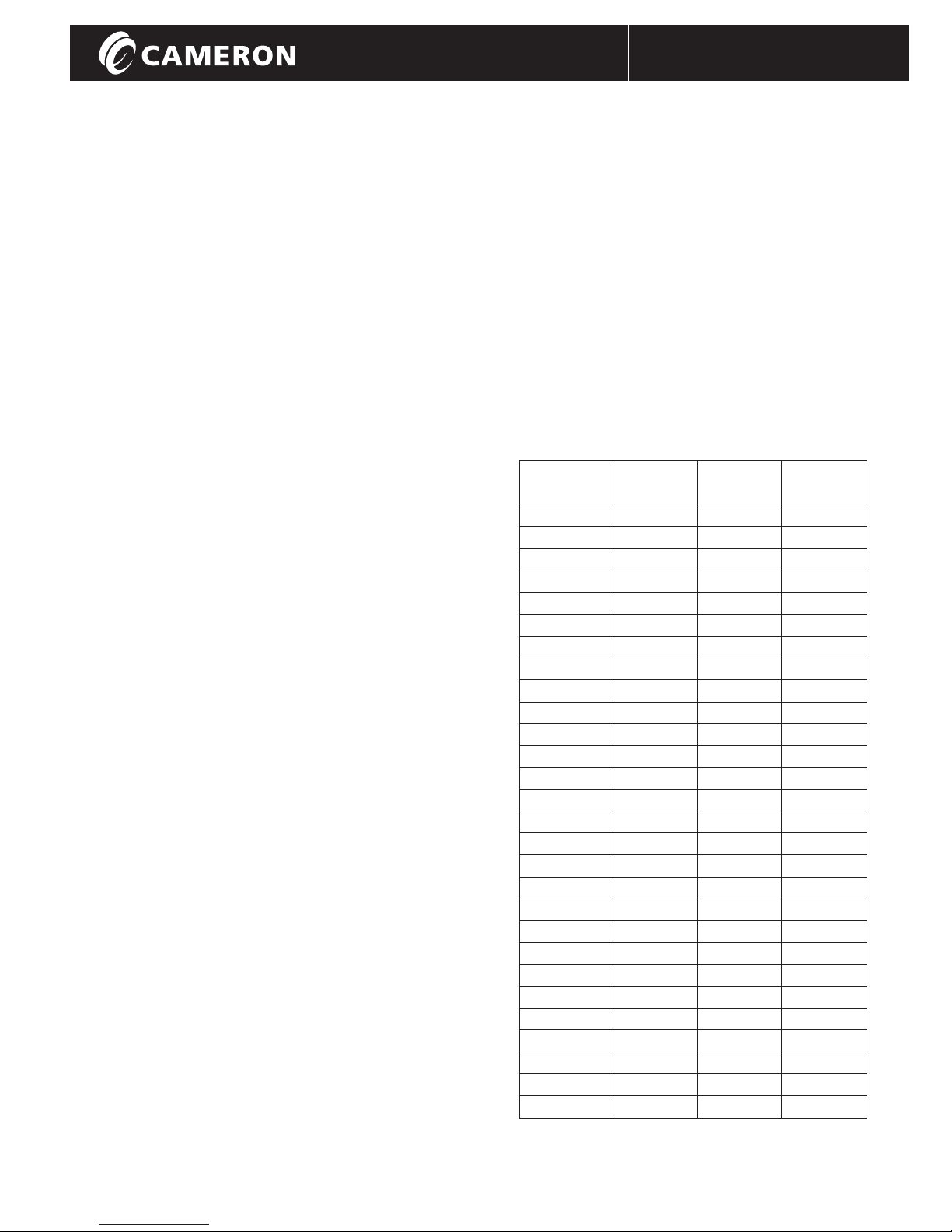
minimum pipe I.D. for proper disc/pipe clearance.
Pipes smaller than those shown in Table 1 will
require a bevel to prevent the disc edge from
scraping on the pipe I.D. damaging the sealing
surface. (See Figure 7).
Minimum Disc/Pipe
Swing Clearance
X
Figure 7
ØD
30°
D I S T R I B U T E D V A L V E S
Seat Retainer
Valve Size Schedule Schedule Minimum
and Class 40 80 Pipe I.D.
2 1/2" - 150 X X 1.69
2 1/2" - 300 X X 1.69
3" - 150 X X 2.63
3" - 300 X X 2.63
4" - 150 X X 3.65
4" - 300 X X 3.65
5" - 150 X X 4.61
5" - 300 X X 4.61
6" - 150 X 5.83
6" - 300 X 5.83
8" - 150 X 7.87
8" - 300 X X 7.65
10" - 150 X 9.85
10" - 300 X X 9.60
12" - 150 X 11.8
12" - 300 X 11.63
14" - 150 X 12.55
14" - 300 X X 12.4
16" - 150 X 14.45
16" - 300 X X 14.23
18" - 150 X 16.45
18" - 300 X X 16.05
20" - 150 X 18.12
20" - 300 X X 17.82
24" - 150 X 21.71
24" - 300 X X 21.5
30" - 150 X X 28.02
36" - 150 X 34.12
5
IOM-WKM-HPBV-MBInstallation, Operation and Maintenance Manual
Page 8
Gaskets
Non-asbestos gaskets made in accordance with
ASME B16.5, Group 1a and 1b are standard for the
The WKM DynaCentric MB High Performance
Butterfly Valve.
ASME 16.20 standard spiral wound gaskets may
also be used. Slip-in seat retainers provide 100%
gasket contact. The screw heads of bolt-in seat
retainers protrude into the gasket surface less than
33%.
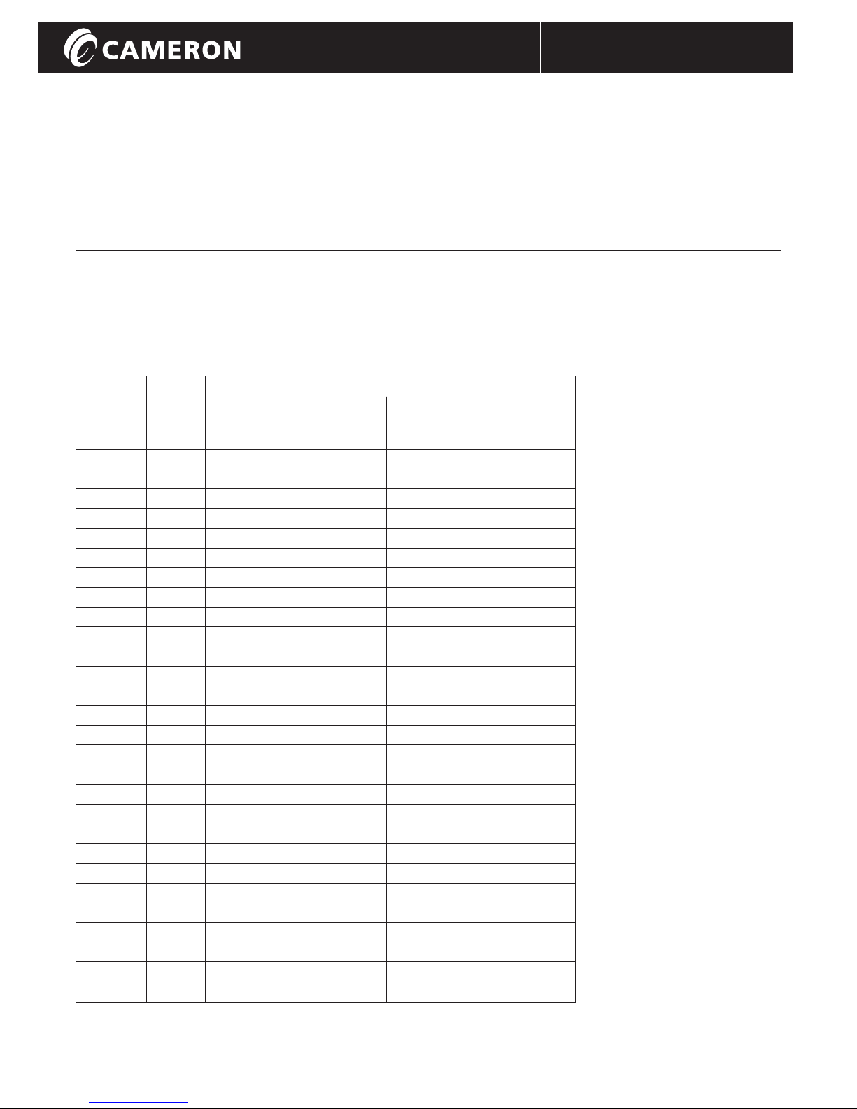
Flange Bolts
Recommended bolt and stud lengths for installation in ASME B16.5 flanges are
provided in Table 2.
Valve Bolt Bolt Wafer Body Lug Body
Size Circle Size Qty. Stud Capscrew Qty. Capscrew
(in.) Dia. (in.) Length 'A' Length 'B' Length 'B'
2 1/2" - 150 5 1/2 5/8-11 UNC 4 5.25 - 8 1.75
2 1/2" - 300 5 7/8 3/4-10 UNC 8 5.75 - 16 1.75
3" - 150 6 5/8-11 UNC 4 5.50 - 8 1.75
3" - 300 6 5/8 3/4-10 UNC 8 6.25 - 16 2.00
3" - 600 6 5/8 3/4-10 UNC 8 6.75 - 16 2.25
4" - 150 7 1/2 5/8-11 UNC 8 5.75 - 16 2.00
4" - 300 7 7/8 3/4-10 UNC 8 6.50 - 16 2.25
5" - 150 8 1/2 3/4-10 UNC 8 6.00 - 16 2.00
5" - 300 9 1/4 3/4-10 UNC 8 7.00 - 16 2.25
6" - 150 9 1/2 3/4-10 UNC 8 6.25 - 16 2.00
6" - 300 10 5/8 3/4-10 UNC 12 7.25 - 24 2.50
8" - 150 11 3/4 3/4-10 UNC 8 6.75 - 16 2.25
8" - 300 13 7/8-9 UNC 12 8.25 - 24 3.00
10" - 150 14 1/4 7/8-9 UNC 12 7.25 - 24 2.50
10" - 300 15 1/4 1-8 UNC 16 9.50 - 32 3.25
12" - 150 17 7/8-9 UNC 12 7.75 - 24 2.75
12" - 300 17 3/4 1 1/8-8 UN 16 10.50 - 32 3.75
14" - 150 18 3/4 1-8 UNC 12 9.00 - 24 3.00
14" - 300 20 1/4 1 1/8-8 UN 16 (8) 12.00 (3.70) 40 3.75
16" - 150 21 1/4 1-8 UNC 16 9.50 - 32 3.00
16" - 300 22 1/2 1 1/4-8 UN 16 (8) 13.00 (3.75) 32 (8) 4.00 (3.75)
18" - 150 22 3/4 1 1/8-8 UN 16 10.50 - 32 3.50
18" - 300 24 3/4 1 1/4-8 UN 20 (8) 14.00 (3.75) 40 (8) 4.00 (3.75)
20" - 150 25 1 1/8-8 UN 20 11.50 - 40 3.75
20" - 300 27 1 1/4-8 UN 20 (8) 14.50 (4.00) 48 4.00
24" - 150 29 1/2 1 1/4-8 UN 20 13.00 - 40 4.50
24" - 300 32 1 1/2-8 UN 20 (8) 16.50 (4.50) 40 (8) 5.00 (4.50)
30" - 150 36 1 1/4-8 UN 20 (16) 16.50 (4.25) 48 (8) 5.00 (4.25)
36" - 150 42 3/4 1 1/2-8 UN - - - 64 5.50
D I S T R I B U T E D V A L V E S
Wafer Body
Studs and
Hex Nuts
A
Figure 8
Lug Body
Capscrews
B
Figure 9
6
IOM-WKM-HPBV-MBInstallation, Operation and Maintenance Manual
Page 9

Procedure
The following procedure applies to new
installation between standard ASME B16.5
pipe flanges.
When replacing a valve from an existing
installation, clean the flange faces of any
residual gasket material before starting.
Actuation should not be removed from the
valve for installations unless the actuator
must be transferred during replacement.
1. Remove protective covers from valve.
Be sure valve is completely closed.
2. When installing wafer body valves,
install lower flange bolts without
tightening (Figure 10). Position valve
and flange gaskets between flanges,
within the pocket formed by the flange
bolts. Install the remaining flange
bolts, taking care that the gaskets are
centered on the flange faces (Figure 11).
Note: While the WKM DynaCentric
MB High Performance Butterfly
Valve has bi-directional sealing
capabilities, the preferred position
is seat upstream (Figure 4).
Handle operated valves or fail close
valves should be installed seat
downstream (stem side facing flow).
3. Lug body valves should be positioned
between the flanges with gaskets
properly centered and then the
capscrews inserted (Figure 12).
4. Carefully check disc clearance by
placing the valve in the full open
position. Should automated valves be
difficult or impossible to cycle, check
that the raised face of the flange
matches the raised area on the valve
face.
5. Tighten all bolts or capscrews in a
crossover or star pattern to insure
even sealing (Figures 11 and 12).
6. Packing gland tightness is pre-tested
at the factory. Should stem leakage
occur at start-up, the gland can be
adjusted to stop the leak.
Avoid over tightening which may
result in excessive operating torque
or premature packing wear.
D I S T R I B U T E D V A L V E S
Raised Face
Area
Figure 10
Wafer Body
Figure 11
Lug Body
Figure 12
7
IOM-WKM-HPBV-MBInstallation, Operation and Maintenance Manual
Page 10

Operation
Manually Operated
The WKM DynaCentric MB High Performance
Butterfly Valve operates from fully open to fully
closed by a 90° turn of the handle.
Visual "OPEN - CLOSED" indicators on the stop
plate and handle enable the valve's position to
be determined at a glance.
The 3" through 6" WKM DynaCentric MB High
Performance Butterfly Valves have flatted stems.
The larger valves have a single square key.
Both stem flats and keyway indicate valve
position. When they are in line with the flow
stream, the valve is open. When perpendicular,
the valve is closed.
In all cases, when the valve is closed, the handle
is perpendicular to the run of the pipe (Figure 13)
and when the valve is open, the handle is parallel
to the pipe (Figure 14).
Maximum recommended pressure differential for
handle operated valves:
2 1/2"......... 450 psi
3" .............. 400 psi
4" .............. 300 psi
5" .............. 200 psi
6" .............. 150 psi
8" .............. 50 psi
D I S T R I B U T E D V A L V E S
Worm Gear Operated
Worm gear operators, available as standard
equipment on all valves 8" and larger, which are
not power actuated, have an arrow on top of the
operator that indicates the "OPEN - CLOSED"
position of the disc (Figure 15).
Counter-clockwise rotation of the handwheel
opens the valve; clockwise rotation closes the
valve.
Figure 13
Figure 15Figure 14
8
IOM-WKM-HPBV-MBInstallation, Operation and Maintenance Manual
Page 11
Routine Maintenance
Because of the simple design and operation, the
WKM DynaCentric MB High Performance Butterfly
Valve requires virtually no maintenance. Its nonlubricated construction and protected seat design
provides reliable leak free performance without
routine servicing.
The only preventive maintenance recommended for
the valve is to periodically inspect for leaks around
the stem packing. Should a leak appear, the packing
can be adjusted by tightening the gland retainer nuts
slightly. Avoid excessive tightening which may result
in excessive valve torque or premature packing wear.
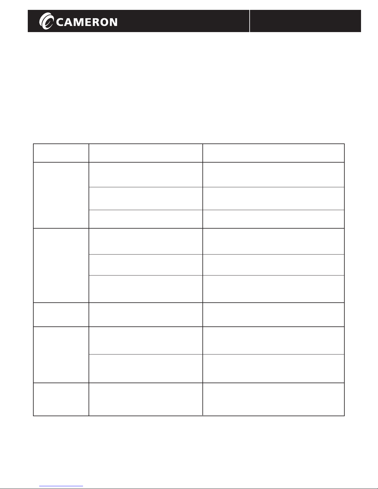
Troubleshooting
Trouble Probable Cause Remedy
The seat and/or disc is worn or Replace worn parts.*
damaged.
D I S T R I B U T E D V A L V E S
The valve will
not seal properly.
The valve is
hard to operate.
The valve
will not open.
The valve is
leaking around
stem.
Foreign matter is present between Operate several times to wipe clean.
seat and disc.
Operator stops are not set properly. Adjust stops to proper setting.
Build up of solids or roughness on Operate several times to wipe clean or
edge of disc. disassemble valve and clean disc edge.*
Stem packing is too tight. Tighten packing only sufficiently to stop leaks.
Operator is not installed properly. Reinstall operator in proper alignment with
valve stem.
Disc hits on side of pipe. Check for proper pipe clearance.
Gland nuts are loose. Tighten gland nuts.
Packing is damaged or worn. Replace packing.
The valve opens
and closes with
line flow.
* Contact your Cameron representative for technical information or repair manual.
Additional information is also available on-line at www.c-a-m.com
Handle or actuator does not provide Restrain handle or actuator when in
proper restraint. static position.
9
IOM-WKM-HPBV-MBInstallation, Operation and Maintenance Manual
Page 12

D I S T R I B U T E D V A L V E S
Contact your Cameron’s Valves & Measurement group representative for a Repair Manual
For the most current contact and location information go to: www.c-a-m.com/valvesandmeasurement
WKM
3250 Briarpark Drive, Suite 300
Houston, Texas 77042
USA Toll Free 800 323 9160
© Cameron’s Valves & Measurement Group Rev. 3 03/10 IOM-WKM-HPBV-MB
IOM-WKM-HPBV-MBInstallation, Operation and Maintenance Manual
®
 Loading...