

Page 1

TOV
Installation, Operation and Maintenance Manual 1 WKM-TOV-IOM
Installation, Operation and Maintenance Manual
3”-24” 150/300/600 CLASS
WKM
®
- TRIPLE OFFSET VALVE
WKM
®
Page 2

TOV
Installation, Operation and Maintenance Manual 2 WKM-TOV-IOM
TABLE OF CONTENTS
List of components 3
Catalog number information 4
Nameplate information 4
Scope 5
Storage 5
Installation 5
Flow direction 5
Shaft position 5
Disc/pipe clearance 6
Disc protrusion length inside pipe 7
Procedure 8
Worm gear operated 8
Valve position verification 12
Routine maintenance 13
Troubleshooting guide 13
Packing maintenance 14
Sealing elements maintenance 15
Bottom cap gasket maintenance 17
Mounting Operators 18
Torque charts 19
© Cameron’s Valves & Measurement Segment Released 07/2018 WKM-TOV-IOM
Notes:
This manual is a general representation of the information required for correct usage of the CAMERON WKM® TOV
valve. More specific information is available and can be supplied per customer request. CAMERON valve reserves
the right to amend this document, with no prior notice. Please reference the applicable drawing and/or parts list
when using this IOM manual.
Page 3

TOV
Installation, Operation and Maintenance Manual 3 WKM-TOV-IOM
List of components
Page 4

TOV
Installation, Operation and Maintenance Manual 4 WKM-TOV-IOM
Catalog number information
Figure number:
The figure number shown below identifies specific valve configuration details of WKM® Triple
Offset Valves such as valve type, pressure class, end connections, body/bonnet and trim
materials, and special features.
Nameplate information
1. Valve size
2. Valve class
3. Seal material See for reference nameplate drawing below.
4. Body material
5. Disc material
6. Shaft material
7. Flange type
8. Figure number
9. Serial number
10. Maximum CWP
Page 5

TOV
Installation, Operation and Maintenance Manual 5 WKM-TOV-IOM
Shaft position
WKM® Triple Offset Butterfly Valves perform equally well
with the shaft in the vertical or horizontal position. Cameron
recommends that the optimum valve installation is with the
shaft in the horizontal plane.
Installing the valve with the shaft at an angle will minimize
any problem associated with solid particles present in the
fluid that otherwise could deposit in the lower bearing area.
Scope
The WKM® Triple Offset Valves are metal seated
butterfly valves. They are designed and manufactured in
a manner that allows the disc to rotate into and out of
the seat with absolutely no interference. This results in a
sealing system that does not depend upon interference
to achieve the seal like other butterfly valves.
Storage
After assembly and test, WKM® Triple Offset Valves
are placed in the closed position. Carbon steel valves
are painted on the external surfaces. Flange
protection is provided for all valves. Valves should be
stored in a clean, dry location. Outdoor storage is
permissible, but should be off the ground and
protected from the elements. For long term storage,
contact your Cameron representative.
Installation
Although WKM® Triple Offset Butterfly Valves have bidirectional sealing capabilities and will operate in any
position, the following positions are generally
recommended.
Flow direction
It is preferred to install the valve in the flow direction
as indicated by the arrow on the valve body. The best
sealing performance will be maintained even when
pressure acts on the non-preferred side of the valve,
however it is recommended to install the valve in the
direction of the flow arrow when the service tightness
requirements are more stringent in one specific
direction (Figure 1).
Figure 1: Flow direction
Flow direction
Page 6

TOV
Installation, Operation and Maintenance Manual 6 WKM-TOV-IOM
Disc/pipe clearance
Before beginning installation, note the following:
Disc/pipe clearance should be checked before
beginning installation to avoid the possibility of
scraping on the seal ring edge on the pipe I.D. and
damaging the sealing surface. Chamfer is
recommended on the pipe flange.
Minimum pipe I.D. required for disc swing clearance:
Class 150 valves - Standard pipe or equivalent
Class 300 valves - Schedule40/XS pipe or equivalent
Class 600 valves - Schedule 100 pipe or equivalent
Consult Table 1 - Disc clearance for required flange
modifications for other pipe schedules (Figure 2).
Table 1 – Disc Clearance
Figure 2: Disc/pipe clearance
Pipe Flange
Page 7
TOV
Installation, Operation and Maintenance Manual 7 WKM-TOV-IOM
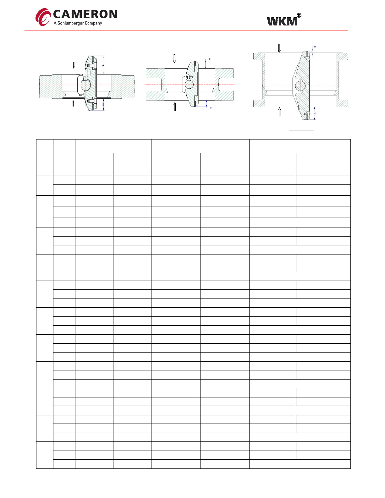
Disc Protrusion length inside pipe
LUG DESIGN
ISO DESIGN
PPE - PREFERRED PRESSURE END
NPPE - NON PREFERRED PRESSURE END
PPE
NPPE
SIZE
CLASS
LUG DESIGN
ISO DESIGN
LP DESIGN
PROTRUSION
ON PPE
SIDE- "A"
(mm)
PROTRUSION
ON NON PPE
SIDE- "B'
(mm)
PROTRUSION ON
PPE SIDE- "X"
(mm)
PROTRUSION ON
NON PPE SIDE- "Y'
(mm)
PROTRUSION ON
PPE SIDE- "M"
(mm)
PROTRUSION ON
NON PPE SIDE- "N'
(mm)
3"
150
21
8
NO PROTRUSION
NO PROTRUSION
NO PROTRUSION
NO PROTRUSION
300
18
11
NO PROTRUSION
NO PROTRUSION
NO PROTRUSION
NO PROTRUSION
4"
150
32
13
NO PROTRUSION
NO PROTRUSION
NO PROTRUSION
NO PROTRUSION
300
28
17
NO PROTRUSION
NO PROTRUSION
NO PROTRUSION
NO PROTRUSION
600
25
10
NO PROTRUSION
NO PROTRUSION
-
6"
150
48
32
4
NO PROTRUSION
NO PROTRUSION
NO PROTRUSION
300
48
32
4
NO PROTRUSION
NO PROTRUSION
NO PROTRUSION
600
23
38.0
NO PROTRUSION
NO PROTRUSION
-
8"
150
69
47
20
10
NO PROTRUSION
NO PROTRUSION
300
63
44
20
10
NO PROTRUSION
NO PROTRUSION
600
46.5
34.5
NO PROTRUSION
NO PROTRUSION
-
10"
150
91
72
39
31
NO PROTRUSION
NO PROTRUSION
300
85
66
39
31
NO PROTRUSION
NO PROTRUSION
600
61.5
51.5
NO PROTRUSION
NO PROTRUSION
-
12"
150
107
86
53
44
NO PROTRUSION
NO PROTRUSION
300
101
80
53
44
NO PROTRUSION
NO PROTRUSION
600
80.0
57.0
9.0
NO PROTRUSION
-
14"
150
119
95
66
52
NO PROTRUSION
22
300
106
84
66
53
NO PROTRUSION
NO PROTRUSION
600
80
66
11.5
1
-
16"
150
139
118
79
66
NO PROTRUSION
44
300
123
104
79
67
NO PROTRUSION
15
600
96
76
25.5
15.5
-
18"
150
166
136
104
92
NO PROTRUSION
63
300
143
124
104
92
NO PROTRUSION
28
600
111.0
88.0
41.0
30
-
20"
150
179
151
120
111
NO PROTRUSION
75
300
159
139
120
111
NO PROTRUSION
30
600
119.5
99.0
48.5
38.0
-
24"
150
221
184
154
142
NO PROTRUSION
109
300
154
142
154
142
NO PROTRUSION
66
600
156
138
74
64
-
NPPE
PPE
LP DESIGN
PPE
NPPE
Page 8
TOV
Installation, Operation and Maintenance Manual 8 WKM-TOV-IOM
Procedure
The following procedure applies to new installation
between standard ASME B16.5 pipe flanges.
When replacing a valve from an existing installation,
The flange faces shall be cleaned of any residual
gasket material before starting.
Actuation shall not be removed from the valve for
installations unless the actuator must be transferred
during replacement.
1. Protective covers shall be removed from the valve.
Be sure valve is completely closed.
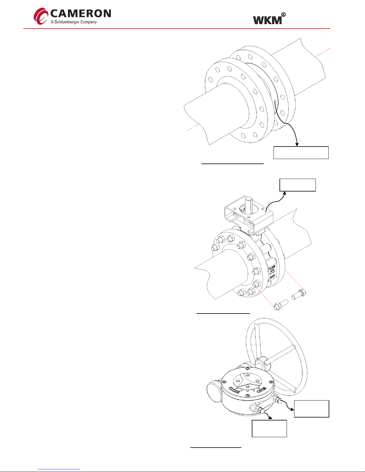
2. Lug body valves shall be positioned between the
flanges with gaskets properly centered and then the
bolting inserted (Figure 4).
3. Disc clearance shall be carefully checked by placing
the valve in the full open position. Should automated
valves be difficult or impossible to cycle, check that the
raised face of the flange matches the raised area on
the valve face.
4. All bolting shall be tightened in a crossover or star
pattern to insure even sealing (Figure 4), refer figure 9
for star pattern tightening method
5. Packing retainer tightness is pre-tested at the
factory. Should shaft leakage occur at start-up, the
packing retainer can be adjusted to stop the leak.
Avoid over tightening which may result in excessive
operating torque or premature packing wear.
Worm gear operated
Worm gear operators, available as standard
equipment on all valves, which are not power actuated,
have an arrow on top of the operator that indicates the
"OPEN - CLOSED" position of the disc (Figure 5)
Counter-clockwise rotation of the hand wheel opens
the valve, clockwise rotation closes the valve.
Raised Face Area
Lug Body
Figure 5: Gearbox
Figure3: Flange detail
Figure 4: Lug body
Close stop
adjustment
Open stop
adjustment
Page 9
TOV
Installation, Operation and Maintenance Manual 9 WKM-TOV-IOM
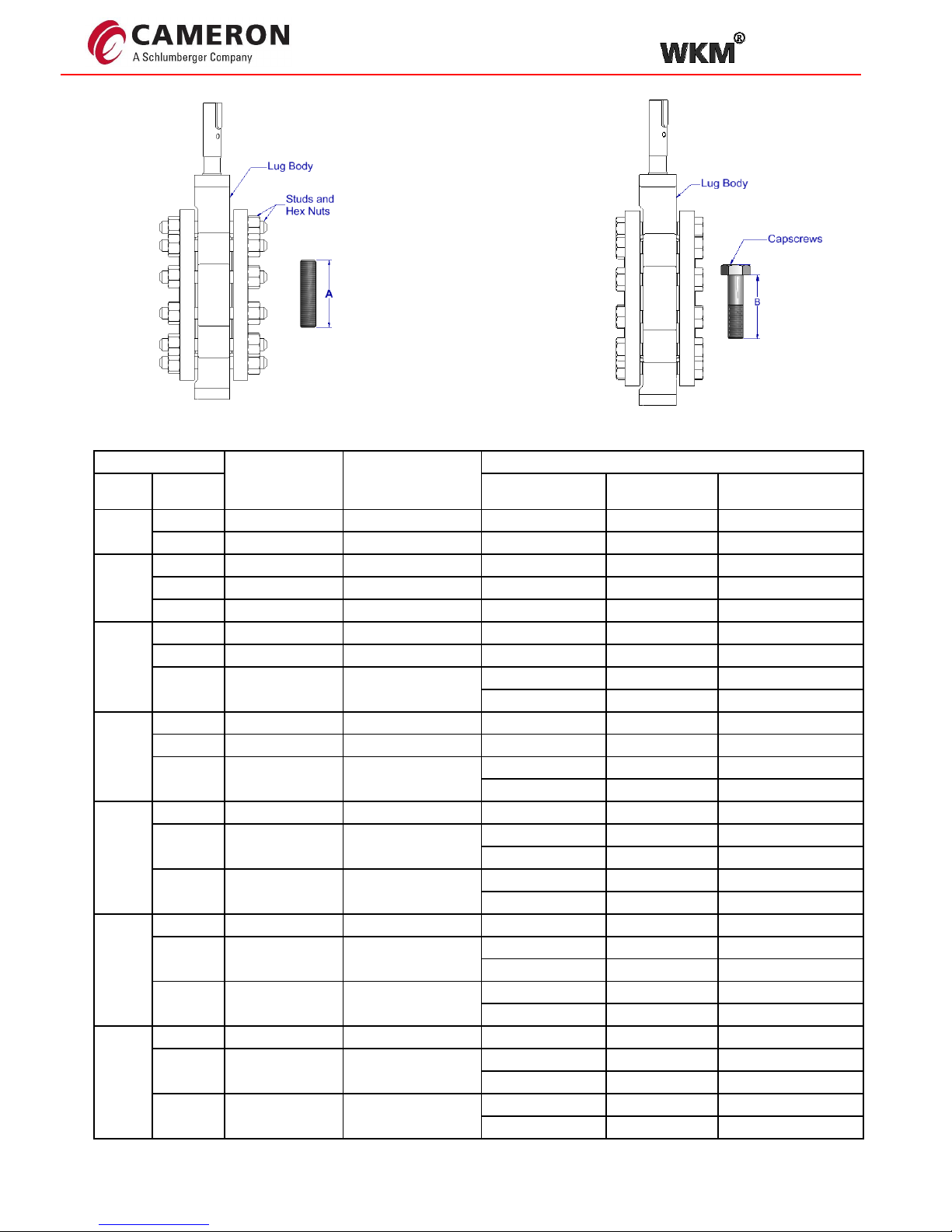
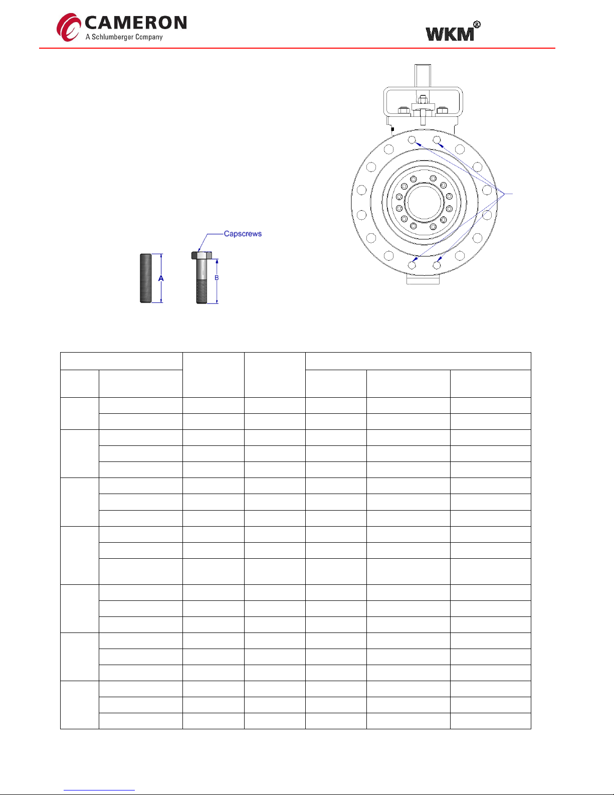
Recommended bolt and stud lengths for installation in ASME B16.5 flanges are provided in the Table 2.
Valve
Bolt Circle
Dia. (in)
Bolt Size
Lug Body
Size
Class
Qty.
Stud length
"A" (in.)
Cap screw length
"B" (in.)
3''
150
6.00
5/8-11 UNC
8
2.70
1.95
300
6.63
3/4-10 UNC
16
3.01
2.13
4''
150
7.50
5/8-11 UNC
16
2.85
2.11
300
7.88
3/4-10 UNC
16
3.29
2.42
600
8.50
7/8-9 UNC
16
4.20
3.20
6''
150
9.50
3/4-10 UNC
16
3.04
2.17
300
10.63
3/4-10 UNC
24
3.56
2.68
600
11.50
1.000-8 UNC
20
4.98
3.85
4
4.10
3.23
8''
150
11.75
3/4-10 UNC
16
3.32
2.45
300
13.00
7/8-9 UNC
24
3.83
2.83
600
13.75
1 1/8-8 UN
20
5.89
4.64
4
4.91
3.65
10''
150
14.25
7/8-9 UNC
24
3.67
2.67
300
15.25
1.000-8 UNC
24
4.41
3.28
8
3.91
2.78
600
17.00
1 1/4-8 UN
24
6.44
5.07
8
5.38
4.01
12''
150
17.00
7/8-9 UNC
24
3.73
2.73
300
17.75
1 1/8-8 UN
28
4.86
3.60
4
4.27
3.01
600
19.25
1 1/4-8 UN
32
6.64
5.27
8
5.51
4.14
14"
150
18.75
1-8 UNC
24
4.22
3.09
300
20.25
1 1/8-8 UN
32
5.26
4.00
8
3.25
3.13
600
20.75
1 3/8-8 UN
32
6.97
5.48
8
4.49
4.37
Note:
For blind threaded holes
stud and nut is preferable
Table 2
Page 10
TOV
Installation, Operation and Maintenance Manual 10 WKM-TOV-IOM
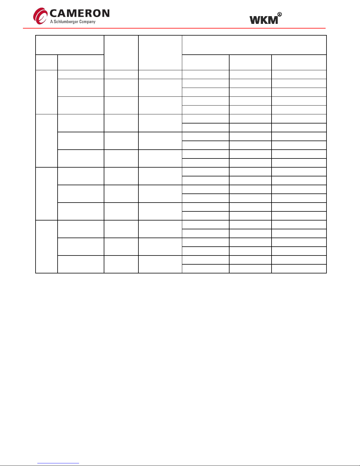
Valve
Bolt Circle
Dia. (in)
Bolt Size
Lug Body
Size
Class
Qty.
Stud length
"A" (in.)
Cap screw length
"B" (in.)
16"
150
21.25
1-8 UNC
32
4.17
3.04
300
22.50
1 1/4-8 UN
32
5.73
4.36
8
4.71
3.34
600
23.75
1 1/2-8 UN
32
7.54
5.92
8
6.32
4.70
18"
150
22.75
1 1/8-8 UN
28
4.77
3.51
4
3.83
2.57
300
24.75
1 1/4-8 UN
40
5.86
4.49
8
4.83
3.46
600
25.75
1 5/8-8 UN
32
8.24
6.49
8
6.78
5.03
20"
150
25.00
1 1/8-8 UN
32
5.02
3.68
8
3.95
2.62
300
27.00
1 1/4-8 UN
40
6.06
4.61
8
5.04
3.59
600
28.50
1 5/8-8 UN
40
8.56
6.74
8
7.19
5.36
24"
150
29.50
1 1/4-8 UN
32
5.32
3.87
8
4.41
2.96
300
32.00
1 1/2-8 UN
40
6.92
5.22
8
5.70
4.00
600
33.00
1 7/8-8 UN
40
9.59
7.51
8
8.02
5.94
Page 11
TOV
Installation, Operation and Maintenance Manual 11 WKM-TOV-IOM
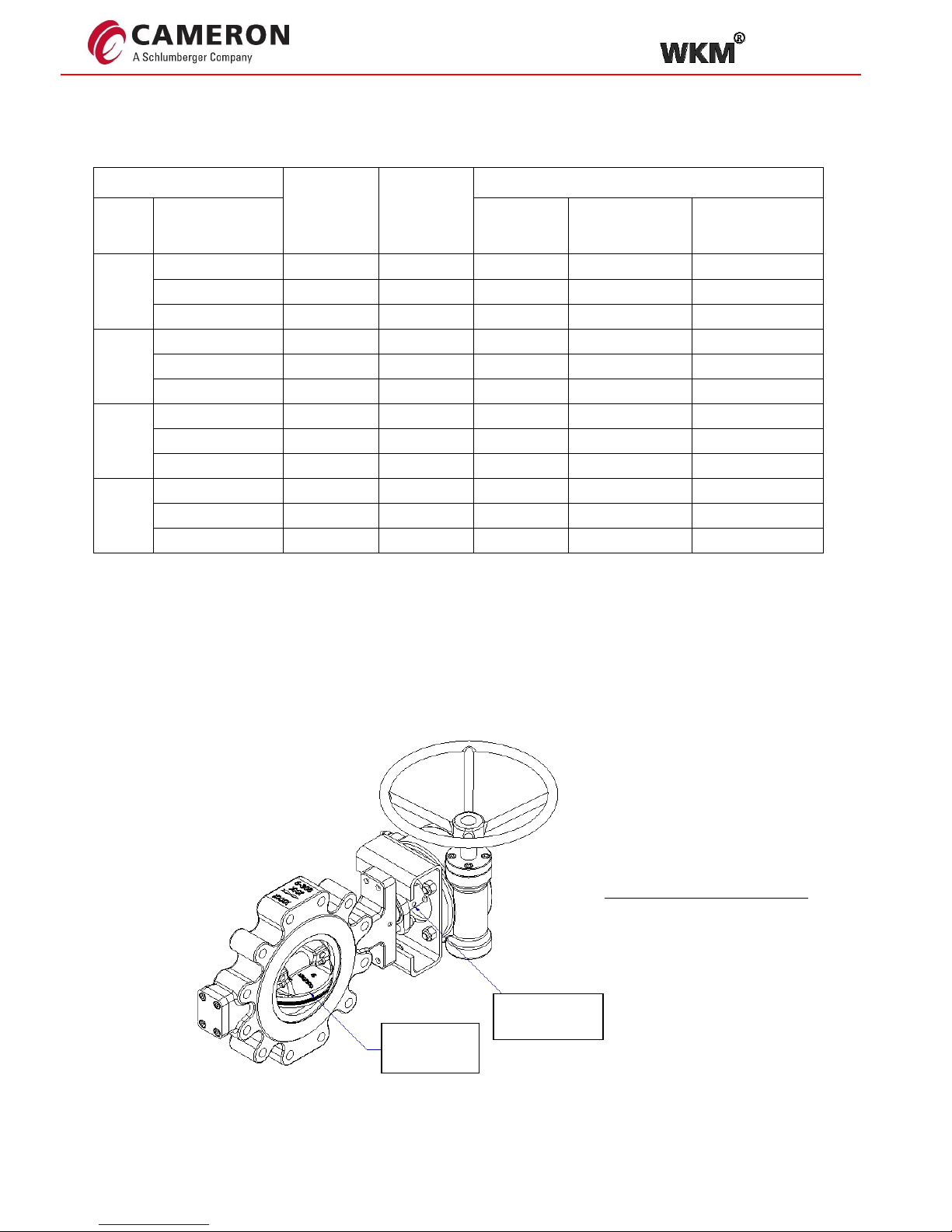
Recommended bolt and stud lengths for installation in ASME B16.5 flanges are provided in the Table 3
Valve
Bolt Circle
Dia. (in.)
Bolt Size
ISO Body
Size
Class
Qty.
Stud length "A"
(in.)
Cap screw
length "B" (in.)
3''
150
6
5/8-11 UNC
_ _ _
300
6.63
3/4-10 UNC
8
3.09
2.21
4''
150
7.5
5/8-11 UNC
8
2.80
2.05
300
7.88
3/4-10 UNC
8
3.13
2.26
600
8.5
7/8-9 UNC
8
4.28
3.28
6''
150
9.5
3/4-10 UNC
8
2.97
2.09
300
10.63
3/4-10 UNC
8
3.40
2.53
600
11.5
1-8 UNC 8 5.18
4.05
8''
150
11.75
3/4-10 UNC
8
3.17
2.29
300
13
7/8-9 UN
8
3.83
2.83
600
13.75
1 1/8-8
UNC 8 5.70
4.44
10''
150
14.25
7/8-9 UNC
8
3.44
2.43
300
15.25
1-8 UNC 8 4.41
3.28
600
17
1 1/4-8 UN
8
6.44
5.07
12''
150
17
7/8-9 UNC
8
3.50
2.50
300
17.75
1 1/8-8 UN
8
4.86
3.60
600
19.25
1 1/4-8 UN
8
6.44
5.07
14"
150
18.75
1-8 UNC 8 4.22
3.09
300
20.25
1 1/8-8 UN
8
5.18
3.92
600
20.75
1 3/8-8 UN
16
6.97
5.48
Table 3
ISO 5752 Flanged Body style
For ISO body style valves, the flange free holes
shall be assembled with studs whose lengths are as
specified in the standard ASME B 16.5 and threaded
holes shall be assembled with the bolts and studs whose
lengths are as recommended in table 3.
Threaded hole
Quantity
specified in
Table 3.
Page 12
TOV
Installation, Operation and Maintenance Manual 12 WKM-TOV-IOM
Recommended bolt and stud lengths for installation in ASME B16.5 flanges are provided in the Table 3
Valve
Bolt Circle
Dia. (in.)
Bolt Size
ISO Body
Size
Class
Qty.
Stud length
"A" (in.)
Cap screw
length "B" (in.)
16"
150
21.25
1-8 UNC
8
4.29
3.16
300
22.5
1 1/4-8 UN
8
5.42
4.05
600
23.75
1 1/2-8 UN
16
7.58
5.96
18"
150
22.75
1 1/8-8 UN
8
4.61
3.36
300
24.75
1 1/4-8 UN
8
5.54
4.17
600
25.75
1 5/8-8 UN
16
7.84
6.09
20"
150
25
1 1/8-8 UN
8
5.02
3.68
300
27
1 1/4-8 UN
8
5.75
4.30
600
28.5
1 5/8-8 UN
16
8.05
6.22
24"
150
29.5
1 1/4-8 UN
8
5.12
3.67
300
32
1 1/2-8 UN
8
6.64
4.94
600
33
1 7/8-8 UN
16
9.12
7.04
Valve position verification
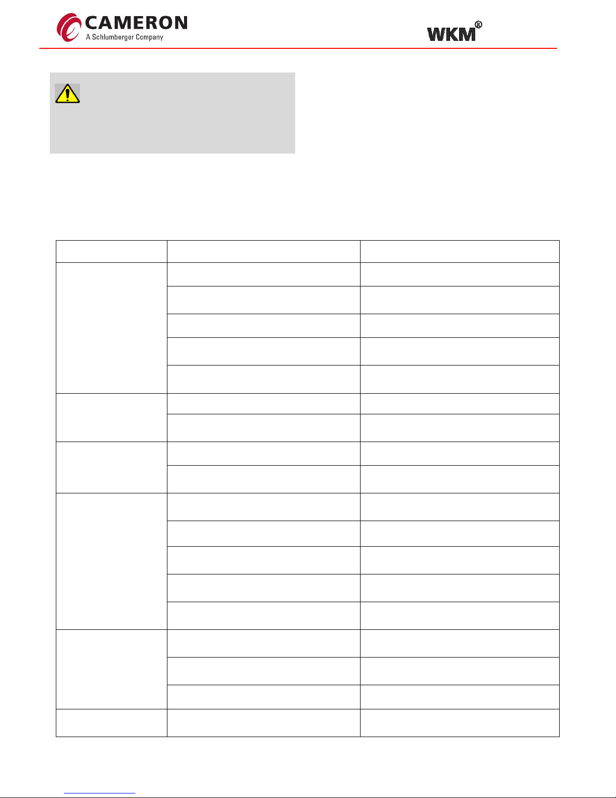
1. Check the operation of the valve by stroking it to "full open" and "full close". To verify the valve orientation, the disc
position is accomplished by dimple on shaft. When the dimple is inline with flow axis, disc is open (Figure 6).
Disc position
indicator mark
Disc in open
position
Figure 6: Position indicator
Table 3
Page 13
TOV
Installation, Operation and Maintenance Manual 13 WKM-TOV-IOM
Troubleshooting guide
Symptom
Possible Cause
Resolution
Valve does not seal
properly
1. Valve not fully closed.
1. Close valve.
2. Foreign matter is present between seat
and disc.
2. Operate several times to wipe clean.
3. Operator stops are not set properly.
3. Adjust stops to proper setting.
4. The seat and/ or disc is worn or
damaged.
4. Replace worn parts.
5. Seat retainer screws are not tight.
6. Tighten seat retainer screws as per
torquing method.
Valve is leaking around
the stem
1. Packing retainer flange nuts too loose.
1. Tighten packing nuts.
2. Packing damaged.
2. Replace packing - See “Packing
maintenance”.
Bottom cap gasket
leaking
1. Bottom cap bolting loose.
1. Tighten bottom cap bolting.
2. Spiral wound gasket damage.
2. Replace spiral wound gasket – See
“Bottom cap gasket maintenance”.
Valve is hard to rotate
1. Shaft packing too tight.
1. Tighten packing only sufficiently to stop
leaks.
2. Operator failed/ not installed properly.
2. Replace or repair.
3. Build up of solids or roughness on edge
of disc.
3. Operate several times to wipe clean or
disassemble valve and clean disc edge.
4. Shaft key has sheared.
4. Determine cause of shearing and
correctly replace shaft key.
5. Fluid solidification between bearings
and shaft.
5. Flush bearings.
Jerky operation
1. Packing is too tight.
1. Loosen packing nuts, cycle valve,
retighten.
2. Air supply inadequate for the actuator.
2. Increase air supply pressure and/or
volume.
3. Actuator/shaft adapter misaligned.
3. Remove actuator mounting and realign.
The valve will not open
1. Disc hits on side of pipe.
1. Check for proper pipe clearance.
Routine maintenance
Caution:
The line shall be depressurized before starting any
maintenance. Failure to do so may cause serious
personal injury and or equipment damage.
Because of the simple design and operation, WKM®
Triple Offset Valves require virtually no maintenance.
Its non-lubricated construction provides reliable leak free
performance without routine servicing.
The only preventative maintenance recommended for
the valve is to periodically inspect for leaks around the
shaft packing. Should a leak appear, the packing can be
adjusted by tightening the packing retainer nuts slightly.
Avoid excessive tightening which may result in excessive
valve torque or premature packing wear.(Refer Chart B
for recommended retainer torque values)
Page 14
TOV
Installation, Operation and Maintenance Manual 14 WKM-TOV-IOM
Packing maintenance
Caution:
Torque shall be applied accurately per Torque chart
‘B’. Over torquing will increase the opearting torque of
the valve and will also negatively effect the packing life.
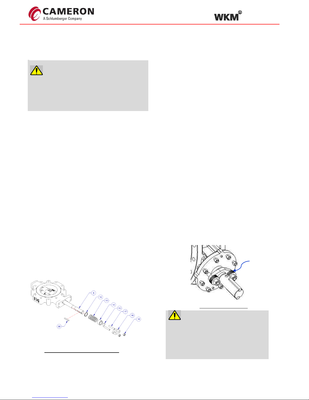
1. Actuator/ Gear shall be removed including the
connecting Key(s) (30). Actuator position relative
to the valve position shall be noted for
reassembly.
2. Mounting bracket shall be removed from the valve
including the connecting studs/nuts.
3. Packing retainer nuts (18) shall be removed.
Assembly configuration shall be noted for ease of
reassembly later.
4. Packing retainer (16) shall be removed by
removing the nuts (18) and studs (17).
5. Blow-out ring (15) and packing bushing (14) shall
be removed..
6. Packing rings (13) shall be removed followed by
packing washer (12).
If leakage is found around the shaft area through the packing, retainer nuts shall be tightened slowly and evenly
until the leakage stops.
7. Packing cavity shall be cleaned with Light Mineral Oil
and shaft with Molykote ® -P74 (Grease) or
Equivalent.
8. Packing washer (12), new packings (13), packing
bushing (14), blow out ring (15), and packing retainer
(16) shall be reassembled according to the assembly
configuration noted in point 3.
9. Packing retainer nuts (18) shall be assembled by hand
without torque tightening equipment after applying a
thin film of lubricant on the threads of the stud bolts by
Molykote ® -P74 (Grease) or Equivalent can be used.
Keys(s) (30) on the shaft end shall be reassembled.
10. Gear/actuator shall be reassembled and the Valve
shall be closed.
11. Packing retainer nuts (18) shall be tightened in
accordance with Torque chart “B” (Torque values for
packing nuts).
12. If a leak is detected, pressure shall be released and
packing retainer nuts shall be tightened (18) slowly
and evenly until the leak stops.
Figure 7: Packing maintenance
Belleville Spring
Live loaded Packing
Caution:
For live loaded packing design, make sure to
note down the sequence and pattern of the
belleville springs before removing them.
The live load packing nuts shall be tightened in
accordance with Torque chart “B”.
Page 15
TOV
Installation, Operation and Maintenance Manual 15 WKM-TOV-IOM
Sealing elements maintenance
Packing maintenance
Fig: 4.1
using Molykote ® Spray – 321 R (Dry lubricant) or
equivalent and also to the external edge (sealing
conical surface) of the seal rings.
15. The disc (6) shall be rotated 90° clockwise (fully open
position from 180°).
16. The gear box (31) shall be assembled.
17. The valve shall be seated and unseated twice by using
the gear box.
18. The valve shall be kept in the closed position without
applying torque to avoid the seal ring moving from the
position.
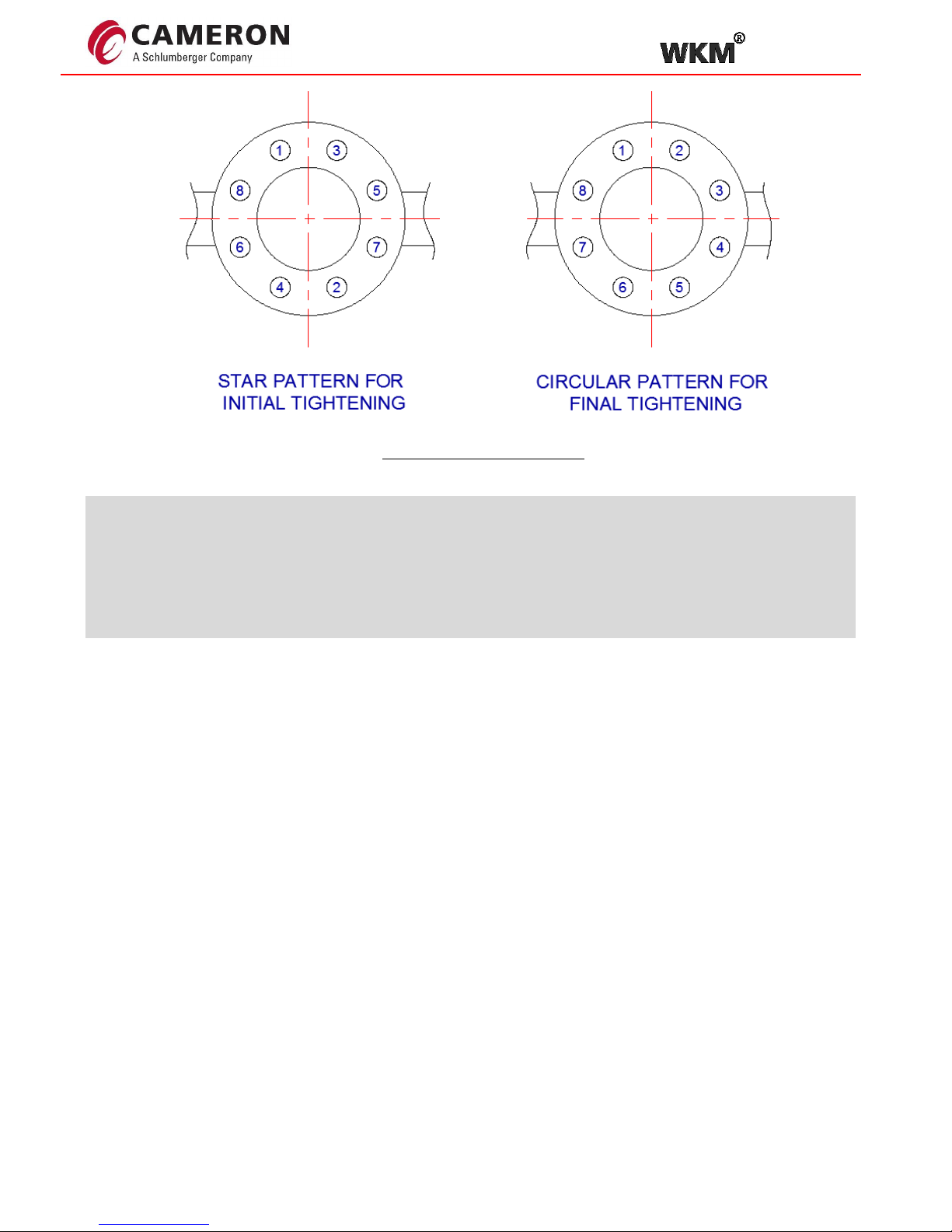
19. With the valve in the closed position, all the retaining
ring screws (29) shall be tightened using star pattern
as per Figure 9.
a. Packing nuts are tightened as per the torque
chart.
Caution:
Bolt torque shall be applied in small increments (25 percent
of final torque) so that gasket is compressed evenly.
Caution: Seal and seat shall contact uniformly
around circumference. No light shall be visible around seal.
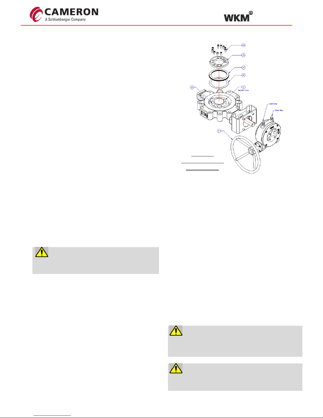
1. The valve shall be removed from the line with the disc (6)
in the closed position.
2. The valve shall be fully open (90°) by using the gear box
(31).
3. The gear box (31) shall be removed from the valve.
4. The valve shall be opened further 90° counterclockwise
(up to 180° from the closed position along with shaft
[Figure 8]).
a. If needed, the packing nuts shall be loosened for
frictionless rotation.
5. The seal retainer screws (29) shall be removed and the
seal retainer shall be carefully removed (28).
6. The seal ring assembly (27) and the graphite gasket (26)
shall be removed.
7. The body seat shall be inspected and cleaned with a fine
abrasive cloth (No. 600 or finer), if necessary.
8. The disc seal ring area and serrations shall be inspected
and cleaned. No foreign particles shall be present on the
serrations where GHR gasket (26) will be placed.
9. A thin film of light mineral oil shall be applied on the
surface area of the disc where seal ring (27) will be
located.
Caution:
Serration surfaces shall be fully cleaned such that no
foreign particles are present.
10. The new GHR gasket (26) shall be assembled on the
serration surface.
11. Seal ring (27) shall be replaced after making sure that the
slot on the edge of the seal ring (27) is in correspondence
with the locating pin (25).
12. The seal retainer ring (28) shall be assembled after making
sure that the slot on the edge of the seal ring (27) is in
correspondence with the locating pin (25).
13. All the fastening screws (29) shall be hand tightened after
applying Loctite ® type 242 or equivalent on the threads.
Then, verify that the seal ring can be moved freely by hand
without rotating it.
14. A thin film of lubricant shall be applied to the body seat
Figure 8:
Sealing elements
maintenance
Page 16
TOV
Installation, Operation and Maintenance Manual 16 WKM-TOV-IOM
Note:
Bolting shall be hand tightened for positioning of the seal ring assembly into the seat face without any damage. Refer
to the torquing method for fasteners as mentioned below.
Torquing method for fasteners:
✓ Use star pattern – torque socket head cap screw 25% of required bolt torque
✓ Use star pattern – torque sockethead cap screw 50% of required bolt torque
✓ Use star pattern – torque sockethead cap screw 75% of required bolt torque
✓ Use star pattern – torque sockethead cap screw 100% of required bolt torque
✓ Use circular pattern – repeat 100% bolt torque to equalize load.
A. Gear box: “Close stop adjustment”
Using gear box, back out close stop adjustment 5 turns. Apply handwheel torque to close valve completely. Turn
stop in until contact and lock the Position with jam nut as shown in the figure 5.
B. Gear box: “Open stop adjustment”
Open valve and visually align disc assembly parallel to valve bore (full Open). Set the open stop adjustment of the
gear box and lock the position With jam nut as shown in the figure 5.
Figure 9: Torquing method
Page 17
TOV
Installation, Operation and Maintenance Manual 17 WKM-TOV-IOM
Bottom cap gasket maintenance
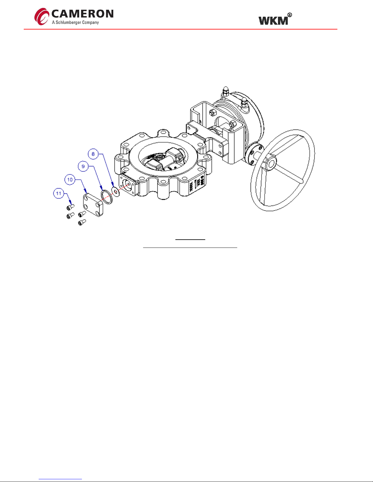
The following procedure shall be followed, when replacing the bottom spiral wound gasket (Figure 10).
`
1. The bottom cap socket head cap screws (11) shall be loosened and the bottom flange (10) shall be
removed.
2. The spiral wound gasket (9) shall be removed.
3. The spiral wound gasket groove in the bottom cap shall be inspected and cleaned.
4. A thin film of lubricant, Light Mineral Oil, shall be applied on the new spiral wound gasket (9).
5. The spiral wound gasket shall then be inserted on the bottom cap (10), it shall also be centered and
positioned on the body bore.
6. The bottom cap shall be rotated to be accommodated to the correct position and the holes shall be
centered with the threaded holes on the body.
7. A thin film of lubricant by Molykote ® – P74 (Grease) or equivalent shall be applied on the threads of the
screws (11), and they shall be fitted and tightened using the appropriate torque value from the torque
chart A.
Figure 10:
Bottom cap gasket maintenance
Page 18

TOV
Installation, Operation and Maintenance Manual 18 WKM-TOV-IOM
Mounting Operators To WKM TOV’s
1. Before mounting the operator, the valve position shall be verified for open and close by using the dimple feature
provided on the stem as mentioned on page 9.
2. WKM TOV’s are torque seated in the closed position and are position seated in the open position, therefore to
achieve valve shut off, a few degrees over travel may be required in the operator. Travel stops shall be adjusted
accordingly.
3. Mounting bracket shall be sufficiently rigid to support operator weights and weight imbalances. Stacking mounting
brackets over one another shall be avoided.
4. Parallelism between the top and bottom surfaces of mounting bracket and the flatness of each of these surfaces
shall be maintained to close tolerances. A maximum deviation of 0.2mm is recommended for Parallelism as well
as for Flatness independently.
5. Mounting bracket bolt holes of the top and the bottom surfaces shall be aligned precisely with each other as well
as with the corresponding bolt holes of the actuator and the valve.
6. Adapters for the valve stem/ operator interface shall be designed and manufactured to prevent eccentricity which
can cause misalignment and possible side loads.
7. For scotch yoke type operators, sizing shall be performed such that the run torque is greater than at least 50% of
the published valve break to open torque.
8. Mounting brackets shall be designed to accommodate for the dowel pins on the valve top flange. For the bracket/
operator interface, it is recommended to secure the alignment by using a dowel pin or a spigot mechanism.
Page 19
TOV
Installation, Operation and Maintenance Manual 19 WKM-TOV-IOM
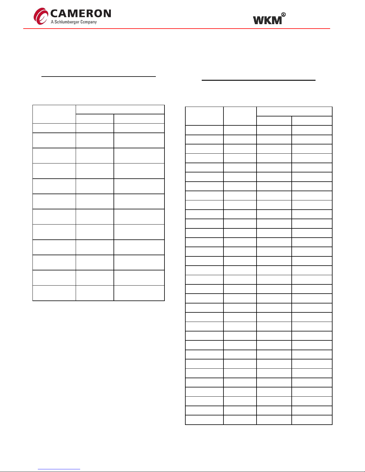
Torque charts
CHART “A” – TORQUE TABLE
(FOR RETAINER, BOTTOM CAP &
CENTER KEY BOLTS)
FASTENERS
SIZE
TORQUES
FT - LB
N.M
M6 x 1.0 5 6
M8 x 1.25
12
16
M10 x 1.5
23
31
M12 x 1.75
39
53
M14 x 2.0
63
86
M16 x 2.0
100
135
M18 x 2.5
160
217
M20 x 2.5
194
263
M22 x 2.5
272
370
M24 x 3.0
337
457
M30 x 3.5
682
925
M36 x 4.0
1204
1633
CHART “B” – TORQUE TABLE
(FOR PACKING NUTS)
SIZE-
CLASS
BOLT
SIZE
TORQUES
FT - LB
N.M
3"-150
M10
11
15
3"-300
M10
15
20
4"-150
M10
15
20
4"-300
M10
15
20
4"-600
M12
21
29
6"-150
M12
22
30
6"-300
M12
26
35
6"-600
M16
52
70
8"-150
M12
22
30
8"-300
M14
33
45
8"-600
M16
41
55
10"-150
M14
33
45
10"-300
M16
44
60
10"-600
M16
48
65
12"-150
M16
44
60
12"-300
M16
52
70
12"-600
M16
52
70
14"-150
M18
74
100
14"-300
M20
103
140
14"-600
M20
95
129
16"-150
M18
81
110
16"-300
M20
111
150
16"-600
M24
129
175
18"-150
M20
103
140
18"-300
M22
133
180
18”-600
M24
142
192
20"-150
M24
177
240
20"-300
M18
89
120
20"-600
M30
229
310
24"-150
M18
89
120
24"-300
M20
103
140
24"-600
M30
275
373
Page 20

TOV
Installation, Operation and Maintenance Manual 20 WKM-TOV-IOM
For the most current contact and location information go to: www.products.slb.com
© Cameron’s Valves & Measurement Segment Released 09/2018 WKM-TOV-IOM
 Loading...