

Page 1

NUFLO™
Align hole in
expansion board
with stando.
Align pins on back
of expansion board
with black headers.
Scanner® 2000 Expansion Board
QuickStart
The Scanner 2000 Expansion Board expands the
Scanner 2000’s input/output to include:
an additional turbine input
•
a pulse input (3-30 VDC or contact closure)
•
two analog inputs (1-5 V, 0-5 V, or 4-20 mA)
•
an analog output (4-20 mA)
•
Installation
Before installing the
expansion board,
remove all power from
the Scanner 2000
(battery and external
power). The expansion
board attaches to two
headers positioned
between the two large
terminal blocks on the
main board. Remove
wiring from the main
board if necessary to
guide the expansion
board into position.
CAUTION: FAILURE TO ALIGN PINS AND HEADERS
CAN DAMAGE THE BOARDS.
Remove the stando
1.
from packaging and
press it into the hole
near the center of the
main board until it
snaps into place.
Guide the expansion
2.
board over the stando and align the pins
on the under side
with the headers on
the main board.
When the board is
positioned correctly,
text on both boards
should face the same
direction.
Gently press the
3.
expansion board and
the main board
together until the
expansion board
snaps into place over
the stando.
Restore wiring con-
4.
nections to the main
board, reconnect the
MVT if disconnected,
and make eld wiring
connections to the
expansion board.
Restore power to the
5.
Scanner 2000 and
reboot the Scanner to
allow detection of the
expansion board.
Part No. 9A-30165026, Rev. 03
Page 2

PULSE INPUT
(TB8)
25 26
TB9
TB8 TB7
TB6
TB4
TB5
PULSE INPUT
3 TO 30 VDC
PULSE INPUT/
SWITCH
(TB7 &TB8)
25
24
26
23
SWITCH
CLOSURE
TB9
TB8 TB7
TB6
TB4
TB5
TB7 AND TB8 ARE
CONNECTED BY JUMPER;
TB7 IS THEN WIRED TO
THE SWITCH.
Expansion
Board PN:
9A-30160014
Expansion
Board PN:
9A-30160014
TURBINE INPUT
(TB9)
TURBINE
MAGNETIC
PICKUP
B
A
2827
TB9
TB8 TB7
TB6
TB4
TB5
Expansion
Board PN:
9A-30160014
Turbine Input 2
The Turbine Input 2
accepts a turbine
owmeter input signal
generated by a magnetic
pickup. The Scanner
2000 can be congured
to use this signal to
calculate and display
instantaneous ow rates
and accumulated totals.
Another turbine input
(Turbine Input 1) is provided on the main circuit
board. When the expansion board is installed, a
dierential pressure ow
run and two turbine runs
can be monitored and
logged simultaneously.
Pulse Input
The pulse input provides
an optically isolated
input for high-amplitude
pulse (frequency) signals,
which includes signals
from a turbine meter
equipped with a
preamplier or signals
from a PD meter (via
contact closure).
The Scanner 2000 can
calculate ow from no
more than two pulse
(frequency) inputs at
a time. Therefore, a
pulse input can be used
simultaneously with only
one turbine input (main
board or expansion
board).
Page 3
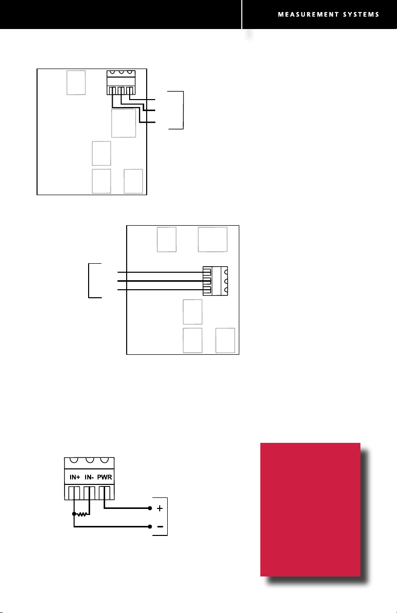
1-5 VDC
TRANSMITTER
POWER
RETURN
SIGNAL
ANALOG INPUT 1
(TB5) WITH 1-5V
TRANSMITTER
17 18 19
TB9
TB8 TB7
TB6
TB5
PWRIN+ IN-
TB4
Expansion
Board PN:
9A-30160014
ANALOG INPUT 2
(TB6) WITH 1-5V
TRANSMITTER
20
21
TB9
TB8 TB7
TB6
TB5
PWRIN+ IN-
22
TB4
Expansion
Board PN:
9A-30160014
POWER
RETURN
SIGNAL
1-5 VDC
TRANSMITTER
Analog Inputs
4-20 mA
TRANSMITTER
Resistor Required
(250-ohm recommended)
TB5
4-20 mA TRANSMITTER WIRING
(CAN BE USED WITH ANALOG INPUT 1 OR 2)
17 18 19
The analog inputs, which
can be congured for a
1-5 V, 0-5 V or 4-20 mA
signal, can receive readings from a pressure or
temperature sensor for
use in AGA-7 gas calculations. Alternatively,
they can be used to log
measurements from any
device with a 1-5 V, 0-5 V
or 4-20 mA output.
Transmitter power is
provided by the Scanner
only when the Scanner is
externally powered. The
output voltage equals
the input voltage less
0.25 VDC, and is limited
to 20 mA.
If a 4-20 mA transmitter
is used, a resistor must
be added to the circuit.
The expansion board
circuit will support a
resistor range of 200 to
300 ohms; 250 ohms is
recommended.
Conguring
Inputs/Outputs
All inputs and outputs
are congured with
ModWorX™ Pro
software provided
with each Scanner
2000 microEFM.
Page 4
15 16
TB9
TB8 TB7
TB6
TB5
Resistor may
be included in
readout device.
*
POWER
–
+
7
8
9
10
11
12
GROUND
SCREW INSIDE
ENCLOSURE
ANALOG READOUT
POWER SUPPLY
8-30 VDC
GND
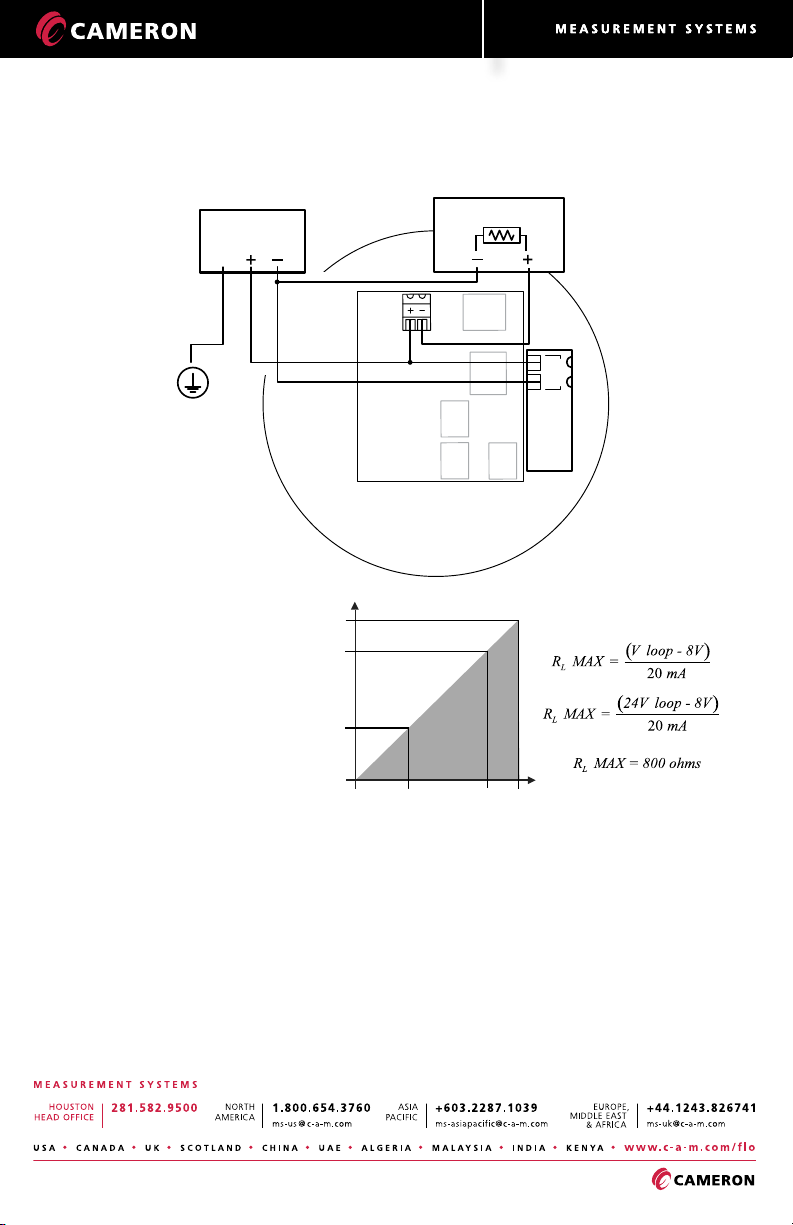
ANALOG OUTPUT (TB4)
WITH POWER SUPPLIED VIA MAIN BOARD (TB2)
SCANNER 2000
Main Circuit Board
PN: 9A-30160010
Expansion
Board PN:
9A-30160014
TB2
TB4
Analog Output
800
200
0
8 12 24 30
OPERATING
REGION
LOOP SUPPLY VOLTAGE (VDC)
LOAD RESISTANCE (OHMS)
(4-20 mA)
The 4-20 mA linear
current output can be
congured with
ModWorX™ Pro
software to represent
any parameter in the
holding registers. This
output requires a twoconductor cable to be
connected to an 8 to 30
VDC power supply (voltage required is dependent on loop resistance)
and an analog readout
device to be located in
the remote location.
The graph above shows
the minimum voltage
required to power the
instrument for a given
loop resistance. In addition, the mathematical
relationship between
loop voltage and load
resistance is given.
For example, if a power
supply voltage of 24
volts is available to
power the current loop,
the maximum load
resistance would be 800
ohms.
 Loading...