


IOMSRD
IOM FOR DYNATORQUE™ SPRING RETURN MANUAL OVERRIDE (SRD TYPE)
Scope:
It is the purpose of this document to provide general installation, operation, storage, and maintenance
instructions for DYNATORQUE™ manual spring return override worm gear operator.
NOTE: DYNATORQUE SRD automated valve manual overrides may be used with electric, hydraulic or
pneumatic spring return valve actuators. For purposes of convention, the term “pneumatic actuator” will
be used to refer to torque-generating driving device (actuator). The term “operator” will refer to the
DYNATORQUE manual override.
Installation Tips:
All Cameron DYNATORQUE operators & accessories have been designed to transmit the rated output
torque of the operator. When designing mounting kits, torque transmission devices, or specifying
mounting hardware the operator rating should be considered. Camero n recommends using grade 5 and
higher bolts with lock washers for mounting DYNATORQUE devices to valve actuators, valve mounting
flanges and/or valve adaptation kits. DYNATORQUE components should not be installed in areas where
those components will be subjected to high temperatures, corrosive atmospheres, or high pressures
without prior knowledge by Cameron or unless originally designed for that purpose. Doi ng so may affect
the product warranty.
Cameron recommends a watertight seal be established at time of installation between the bottom of the
SRD override and the valve, as well as the top of the SRD override and the actuator mounting pad. Apply
a liberal amount of a liquid gasket material (Cameron recommends using DOW Corning RTV #732 multipurpose sealant) on both surfaces prior to SRD override installation. Make sure to surround the mounting
holes with sealant to assure a complete seal.
Installation:
The Cameron DYNATORQUE model SRD manual override operator offers safe and easy positioning of
valves when manually overriding a spring return pneumatic actuator. Each SRD operator comes complete
with a handwheel and machined or blank drive coupling, which can be easily removed for machining to
match the pneumatic actuator and valve stem requirements.
Important Note: Since the external key in the blank drive coupling mentioned above is not contained in
the mating part in a traditional manor, it is necessary to bolt that key to the drive coupling to prevent
possible key roll. The key has been pre-drilled and counter-bored, and hardware has been supplied for
blank drivers. Position the key in the key slot to provide maximum engagement in the override output and
using the key as a guide, drill and tap two holes for the hardware provided.
The following steps should be taken to install the DYNATORQUE SRD override. Cameron recommends
operator mounting while on the test stand with the valve in the fail position.
Proper orientation and initial commissioning of the SRD manual override is a vital step as a part of the
total valve and pneumatic actuator system. [The following information is designed for the installation start-
up procedure of a valve system including a DYNATORQUE SRD override operator. It is critical the
installer verify the pneumatic actuator, the valve, the SRD override, and drive coupling, and any adapting
bracketing are all in the correct orientation when fully assembled.]
2076 NORTHWOODS DR MUSKEGON, MI 49442
PHONE (231) 788-7025 FAX (231) 788-7030
www.dynatorque.com
ISO 9001:2008 CERTIFIED
Revised: 4-15-11
Page 1 of 7
IOMSRD
IOM FOR DYNATORQUE™ SPRING RETURN MANUAL OVERRIDE (SRD TYPE)
The SRD is unidirectional
(counterclockwise rotation as viewed from above) or “Fail CW” (clockwise as viewed from above) with
proper key arrangement and assembly.
Typical Example: Overrides for use with fail closed (CW) actuators:
: The same SRD unit may be used for either, but not both, “Fail CCW”
[Although the pictures show a CW (clockwise) fail closure; the same
mirrored steps can be followed for a CCW (counter-clockwise) fail
closure.
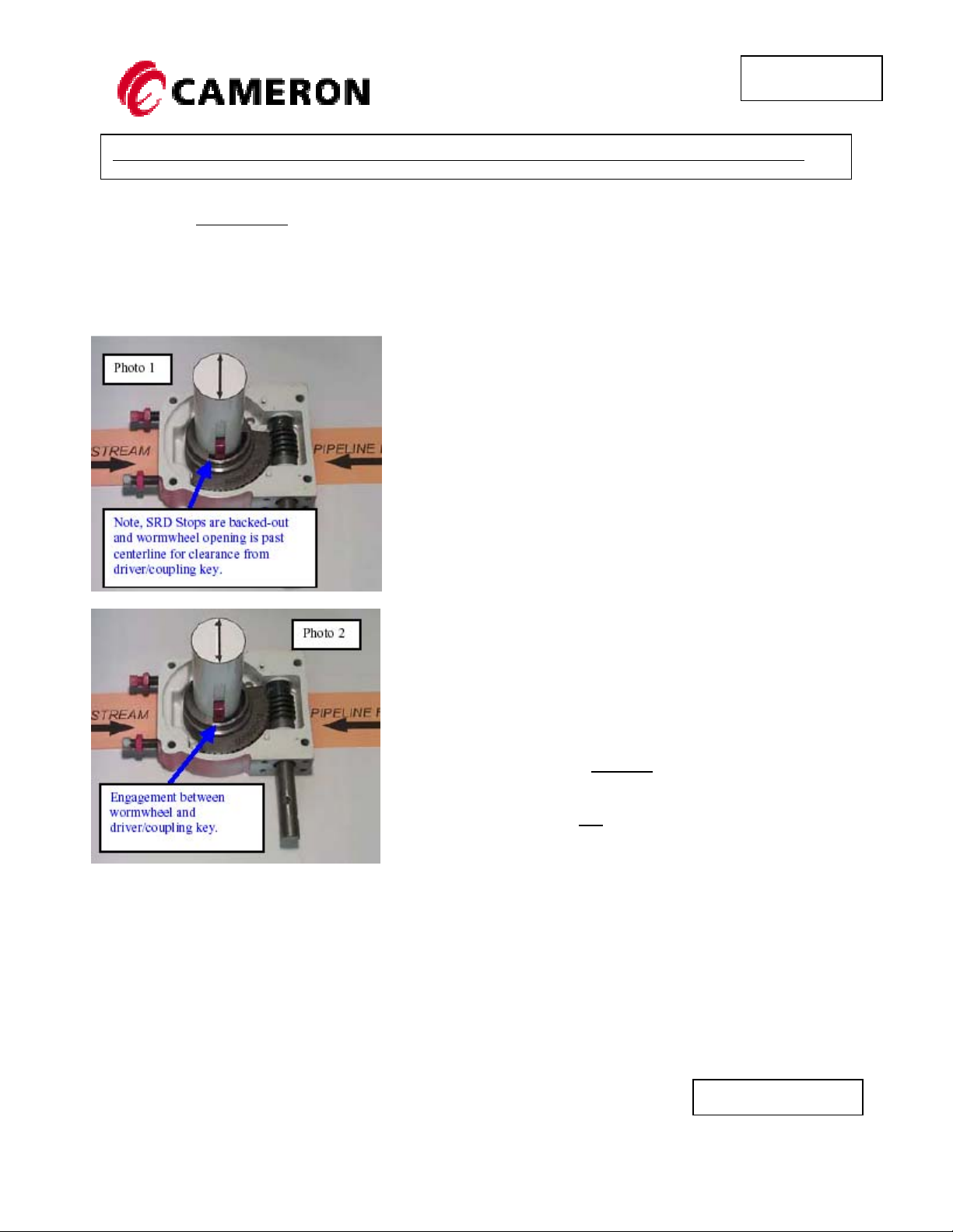
Step 1. Prior to installation in the valve and actuator system, loosen
(back-out) both SRD travel stop bolts from the main housing
approximately six to eight turns (Warning: rotating the stop bolt more
than six to eight turns may allow the worm wheel and worm to
disengage during the next phase of Step 1). Rotate the input shaft
CW which in turn rotates the override output clockwise until the end
of the key slot is just past centerline. (Ref Photo 1).
Step 2. Install the SRD override in the valve and actuator assembly
making sure that the valve and actuator are in the closed position.
Note: Mounting holes on some SRD overrides break into the
housing cavity creating a grease leak path. The use of Teflon
tape is recommended for all valve side bolt installations.
Step 3. Set the pneumatic actuator position stop for full closed
position. The actuators position stop will always be contacted for the
full closed position during normal operation, not the SRD’s stop.
IMPORTANT NOTE: The actuator
must be set to establish the full clockwise and
counterclockwise travel of the actuator. The SRD stops should
be set so that they are not
generated by the actuator.
subject to the rotational force
stops (NOT the SRD stops)
2076 NORTHWOODS DR MUSKEGON, MI 49442
PHONE (231) 788-7025 FAX (231) 788-7030
www.dynatorque.com
ISO 9001:2008 CERTIFIED
Revised: 4-15-11
Page 2 of 7
IOMSRD
IOM FOR DYNATORQUE™ SPRING RETURN MANUAL OVERRIDE (SRD TYPE)
Step 4. Rotate the SRD input shaft CCW until the key
in the drive coupling comes into contact with the end of
the key slot and the coupling just begins to turn. (Ref
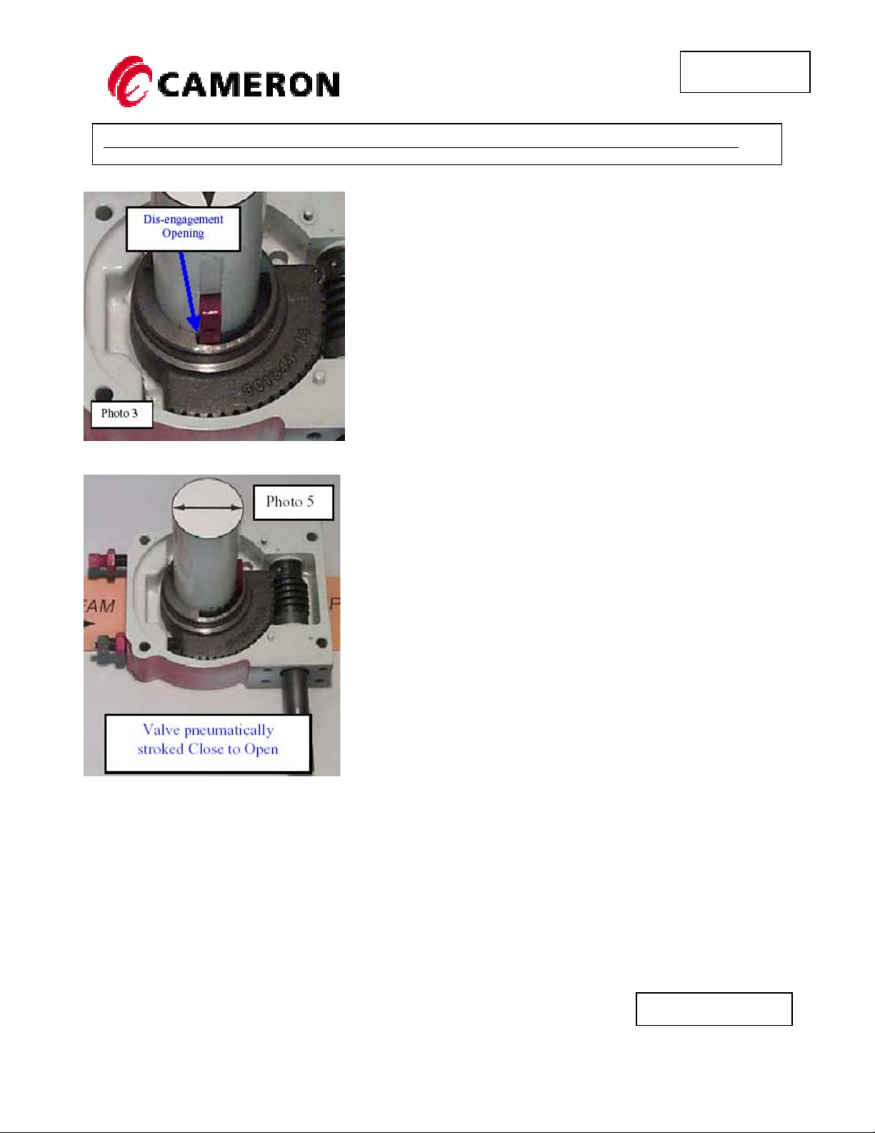
Photo 2). Upon contact, reverse the SRD input shaft ½
to ¾ of a turn to disengage the drive coupling key from
the worm wheel. This will put a very small opening
between the key slot and the drive coupling key. This is
the SRD unit’s Home Position. (Ref Photo 3)
Step 5. Set the SRD travel stop for the closed position (Home
Position) by turning the bolt clockwise until the bolt comes into
contact with the end of the worm wheel. Reverse the bolt ½
turn to ensure that the SRD travel stop is not used as the
primary seating element for the pneumatic actuator. Tighten
the lock/jam nut against the body of the override. (Note: If the
SRD override has been optionally equipped with the Home
Position Indicating Stop Bolt, the indicating head will be
extended to indicate the SRD override is in the “Home
”
Step 6. Reposition the valve to the full open position using the
pneumatic actuator. (Note: There should be no interruption of
the 90 degree strike of the valve by the SRD or any other
component. If there is an interruption, identify the problem and
make the necessary corrections.) Set the
travel stop for the full valve and actuator open position. (Ref.
pneumatic actuator
2076 NORTHWOODS DR MUSKEGON, MI 49442
PHONE (231) 788-7025 FAX (231) 788-7030
www.dynatorque.com
ISO 9001:2008 CERTIFIED
Revised: 4-15-11
Page 3 of 7
 Loading...