

Page 1
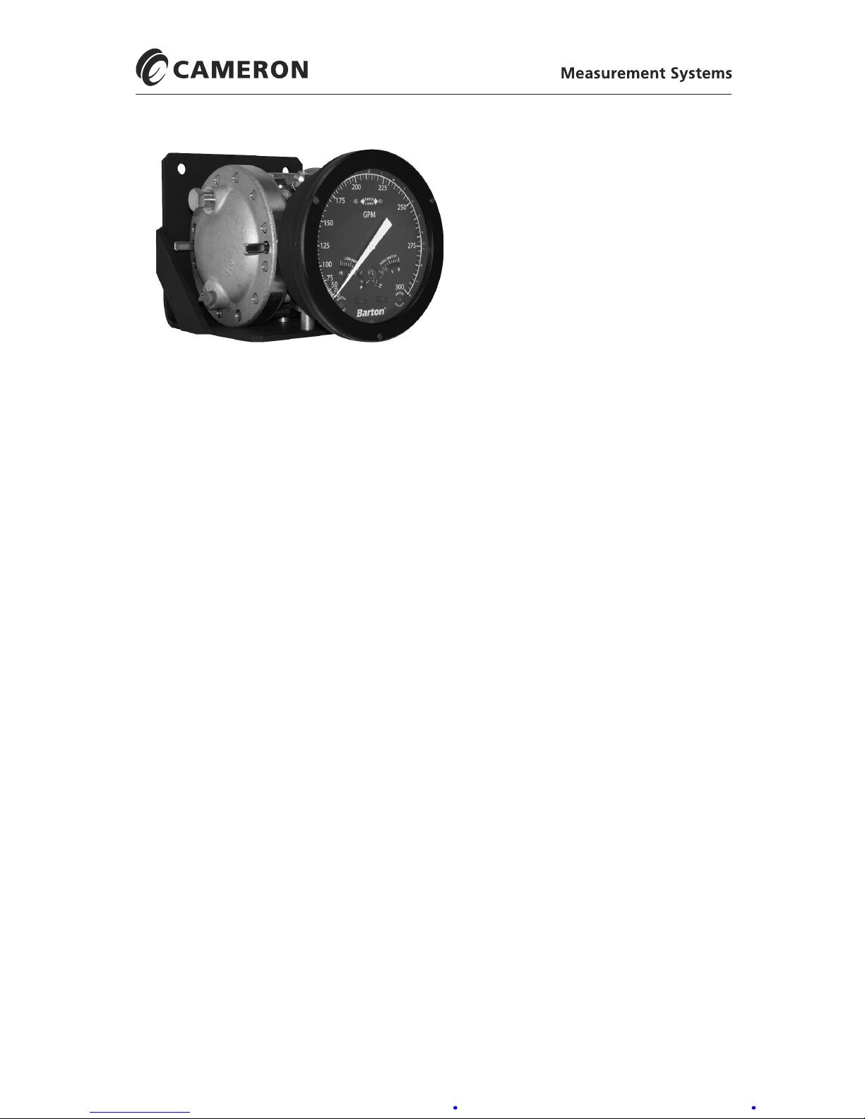
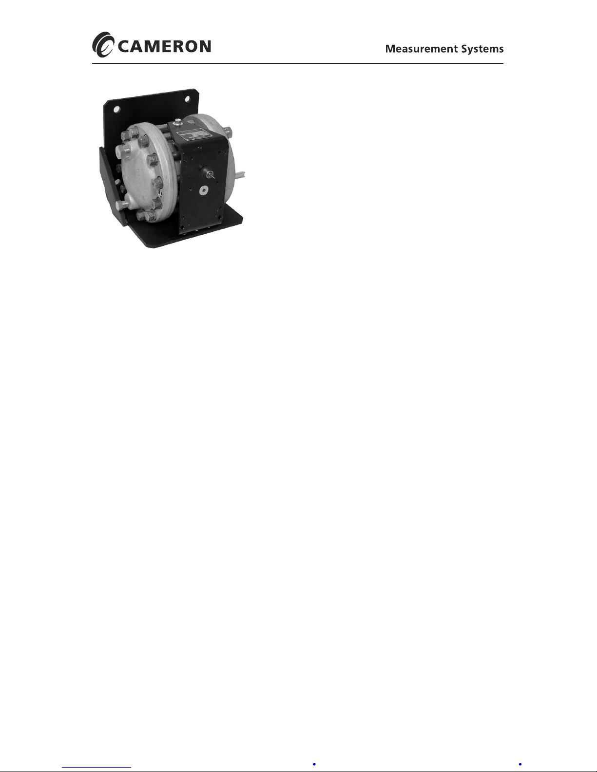
BARTON® NUCLEAR MODEL 289A
DIFFERENTIAL PRESSURE
INDICATING SWITCH
User Manual
Part No. 9A-C10310, Rev. 03
January 2019
Contents
Safety ............................................................................................................ 2
Section 1—Introduction ................................................................................. 3
General ......................................................................................................... 3
Main Components ......................................................................................... 3
Indicating Switch ...................................................................................... 4
Relays ....................................................................................................... 5
Wiring ........................................................................................................ 5
Differential Pressure Unit (DPU) ............................................................... 5
Specications ............................................................................................... 5
Nuclear Qualications ............................................................................... 6
Section 2—Installation ................................................................................... 7
General ......................................................................................................... 7
Mounting/Piping/DPU Installation ................................................................. 7
Electrical Connection (Switches/Relays) ...................................................... 7
Switch Use .................................................................................................... 7
Startup .......................................................................................................... 8
Switch and Relay Wiring Diagrams............................................................... 9
Section 3—Maintenance and Calibration ................................................... 14
Tools............................................................................................................ 14
Bezel/Lens (or Cover) Installation and Removal......................................... 14
Calibration Check........................................................................................ 15
Pointer Installation and Removal ................................................................ 16
Pointer Installation .................................................................................. 16
Pointer Removal ...................................................................................... 16
Indicator Calibration .................................................................................... 17
Drive Arm Tightness Test ......................................................................... 19
Drive Arm Stop Adjustment .................................................................... 20
Switch Calibration ..................................................................................... 20
Calibration Setup ..................................................................................... 20
Calibration Procedure ............................................................................. 21
Page 2

2
Safety
Before installing this product, become familiar with the installation instructions presented in Section 3 and in the Model 199 DPU manual (Appendix A),
and all safety notes throughout.
!
WARNING:Thissymbolidentiesinformationaboutpracticesorcircum-
stancesthatcanleadtopersonalinjuryordeath,propertydamage,or
economic loss.
CAUTION: Indicatesactionsorprocedureswhichifnotperformedcorrectly
mayleadtopersonalinjuryorincorrectfunctionoftheinstrument
orconnectedequipment.
IMPORTANT: Indicates actions or procedures which may affect instrument operation or
may lead to an instrument response that is not planned.
Changing Switch Set Point ........................................................................ 22
Denitions of Terms ................................................................................. 22
Best Practices for Set Points ................................................................... 22
Changing Set Point of an In-Service Instrument (Not Recommended for
Nuclear Qualied Units)
.......................................................................... 23
Changing Set Point of an Out-of-Service Instrument
.............................. 24
Range Changes ...................................................................................... 24
Parts repalcement....................................................................................25
Troubleshooting ......................................................................................... 26
Section4—AssemblyDrawingandPartsLists ......................................... 29
Section5—Installation/DimensionalDrawings ......................................... 35
AppendixA—Model199DPUUserManual ...............................................A-1
Page 3
3
Model 289A Differential Pressure Indicating Switch Section 1
Section 1—Introduction
General
The weatherproof Model 289A is a differential pressure indicating switch.
The Model 289A has a NEMA-4 watertight die-cast aluminum case (nished
with a weather-resistant black epoxy resin paint). The cover lens is secured in
the bezel with an elastomer ring to reduce the possibility of accidental breakage. This ring also acts as a seal between the bezel and the case to ensure a
moisture, fume and dust-free atmosphere for the indicator and switch mechanism. The large cover lens allows maximum readability of the indicating
pointer.
Switches and all adjustments are readily accessible when the cover is removed.
The built-in switches energize either single or dual alarm circuits when the
measured differential pressures exceed predetermined limits. These limits
may be either maximum, minimum, or both.
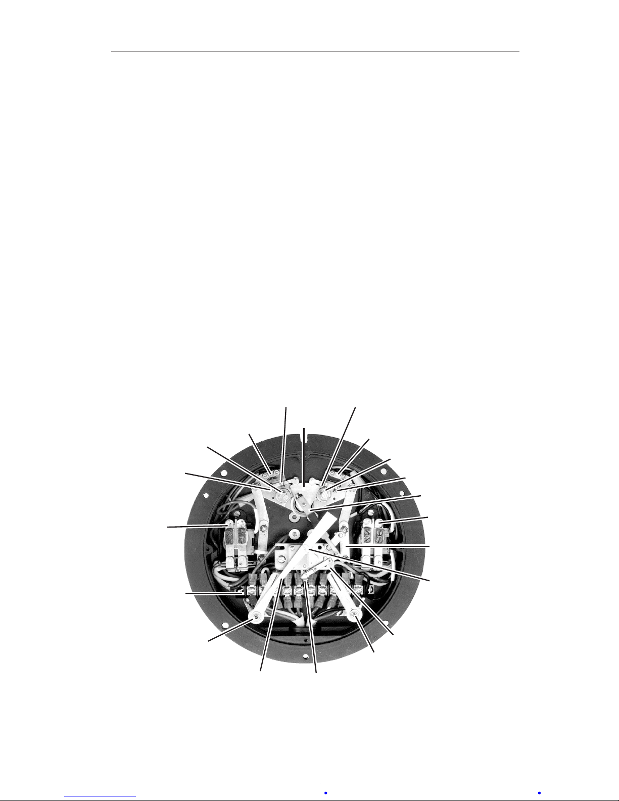
MainComponents
Low Alarm
Relay
Plunger
Screw
Switch
Lock
Low Alarm
Switch
Actuating
Cam
High Alarm
Switch
Switch
Lock
Plunger
Screw
Differential
Drive
Arm
High Alarm
Relay
Hex Hub
Zero
Adjust
Switch Link
Movement
Assembly
High Alarm
Switch
Adjust
Range
Adjust
Pointer
Low Alarm
Switch
Adjust
Terminal
Strip
Stop Screw
Stop Screw
Figure 1.1—Switch components
Page 4

4
Section 1 Model 289A Differential Pressure Indicating Switch
Indicating Switch
(refer to Figure 1.2, Figures 2.1 to 2.6, and Table 2.1)
Rotation of the DPU torque tube shaft is coupled through connecting linkage
within the switch case to move the pointer across the scale plate. An actuating cam, directly connected to the torque tube shaft, rotates with the motion
of the shaft. Two cam follower roller/actuator arm assemblies, one for each
switch, respond to torque tube rotation by opening and closing the switches as
they ride on and off the cam. The levels of differential pressure at which the
switches actuate are adjustable with high and low alarm switch adjustments
on the scale plate.
RED
YELLOW
BLUE
BLACK
1000
50
Mid-point DP
ORANGE
VIOLET
SWITCH
CLOSED
CONTACTS
OPEN
CONTACTS
YELLOW & BLUE RED & YELLOW
VIOLET & ORANGE VIOLET & BLACK
A (LEFT)
B (RIGHT)
1000
50
Zero DP
SWITCH
CLOSED
CONTACTS
OPEN
CONTACTS
YELLOW & BLUERED & YELLOW
VIOLET & ORANGE VIOLET & BLACK
A (LEFT)
B (RIGHT)
1000
50
Maximum DP
SWITCH
CLOSED
CONTACTS
OPEN
CONTACTS
YELLOW & BLUE RED & YELLOW
VIOLET & ORANGEVIOLET & BLACK
A (LEFT)
B (RIGHT)
BOTH SWITCHES RELAXED
SWITCH “A” ACTUATED/SWITCH “B” RELAXED
SWITCH “A” RELAXED/SWITCH “B” ACTUATED
CAM
SWITCH
PLUNGER
SCREW
SWITCH “A”
(LEFT)
LOW
SWITCH “B”
(RIGHT)
HIGH
TERMINAL
BLOCK IN
CASE
SWITCH “A”
(LEFT)
LOW
SWITCH “B”
(RIGHT)
HIGH
SWITCH “A”
(LEFT)
LOW
SWITCH “B”
(RIGHT)
HIGH
Figure 1.2—Switch actuation example
Page 5

5
Model 289A Differential Pressure Indicating Switch Section 1
Standard models can have one or two alarm switches. Each switch can be
connected to operate normally-opened or normally-closed. The direct-set
switch contacts are adjustable over a scale range of 5-95% nominal for SPDT
switches and 6-94% for DPDT switches.
The cam rotates counterclockwise with increased pressure. In Figure 1.2, the
low switch is set at 25% differential pressure, and the high switch is set at
75% differential pressure.
Switches are available in several variations.
• SPDT: This is the standard model (low, high, or both)
• DPDT: Two switches are stacked and actuated by a single lever (low,
high, or both)
• Three or four SPDT: Switches have independent switch points.
Switches 1 and 3 are usually low switches set for decreasing pressures;
switches 2 and 4 are usually high switches set for increasing pressures.
Relays
Relays are actuated by internal switches and are available in several variations:
• one or two SPDT switches
• one or two DPDT switches
Wiring
No. 22 AWG is used for internal wiring and No. 18 AWG is used for external
wiring.
Differential Pressure Unit (DPU)
For detailed information on the DPU, see the Model 199 DPU user manual in
Appendix A.
Specications
General:
Actuating Unit (DPU) ...................... Model 199 DPU
Dial Size ......................................... 6 inches (150 mm)
Temperature Limits (Ambient) ........ -40°F (-40°C) to +180°F (+82°C)
Switch Repeatability ....................... ±0.25% of full scale
Switch Deadband ........................... ±5% (SPDT); ±6% (DPDT)
Switch Type .................................... Mechanical, Snap-Acting; all switches are SPDT
(DPDT switches are stacked SPDT switches with a
common actuator)
Relay Contact Type ........................ Single Pole, Double Throw (SPDT)
Double Pole, Double Throw (DPDT)
Adjustability .................................... 5% to 95% of factory calibrated scale
Activation ........................................ Increasing or decreasing scale
Page 6

6
Section 1 Model 289A Differential Pressure Indicating Switch
Switch Contact Rating:
5.0 Amps @ 125 VAC
5.0 Amps @ 250 VAC, 50/60 Hz
1
3.0 Amps @ 30 VDC (resistive)
1,2
1.0 Amp @ 30 VDC (inductive with arc suppression)
1,2,3
0.4 Amp @ 125 VDC (resistive)
0.2 Amp @ 125 VDC (inductive w/arc suppression)
1. CSA Approved
2. CE Approved (Voltage limited to less than 50 VDC or 35 VAC for CE applications)
3. Arc suppression recommended for inductive loadings
Relay Contact Ratings:
10 Amps @ 150/250 VAC
10 Amps @ 14/28 VDC
1.0 HP @ 208/240 VAC
Relay Coil Voltages:
120 VAC @ 5VA Max.
110 VDC @ 2W Max.
Coil Power Requirement:
DC Relay ........................................ 1.5 Watts
AC Relay ........................................ 2.75 Volt Amps
Accuracy of Indications
Standard (1 or 2 SPDT Switches) .....................±1% of factory calibrated span
(10-349 inches wc)
.....................±1.25% of factory calibrated span
(350 inches wc to 115 psig)
1 or 2 DPDT Switches (S401) .......................... Add ±1/2% to standard accuracy
Near switch setpoint (±10% full scale) ............. Add ±1/2% to standard accuracy
For suppressed ranges .................................... Add ±1/4% to standard accuracy
3 or 4 SPDT Switches ...................................... Add ±3/4% to standard accuracy
Switch Deadband:
SPDT .............................................. ±5% of full scale DP (max)
DPDT .............................................. ±6% of full scale DP (max)
Accuracy of Repeatability ............... ±0.25% of full scale DP
Nuclear Qualications
The following nuclear qualication applications are based on Cameron Engineering
Report 9A-CR3-288A-13 with switch chatter sensitivity addressed in Cameron Engineering Report 9A-CR3-288A-19:
• One or two SPDT switches: Radiation Augmented (3 MRads), Full Functional, 12G,
Mild Environment Applications
• One or two DPDT switches: Structural and Pressure Boundary Integrity Applications
• One or two relays: Structural and Pressure Boundary Integrity Applications
• Three or four independently adjustable SPDT switches: Structural and Pressure
Boundary Integrity Applications
Page 7

7
Model 289A Differential Pressure Indicating Switch Section 2
Section 2—Installation
General
The instrument should be inspected at time of unpacking to detect any damage that may have occurred during shipment.
IMPORTANT: The DPU was checked for accuracy at the factory. Do not change any of
the settings during examination or accuracy could be affected.
For applications requiring special cleaning/precautions, a polyethylene bag
is used to protect the instrument from contamination. This bag should be
removed only under conditions of extreme cleanliness.
Mounting/Piping/DPUInstallation
Dimensional drawings are provided in page 35. See the Model 199 DPU
user manual in Appendix A for DPU installation and maintenance information.
ElectricalConnection(Switches/Relays)
Units are supplied with either single or dual alarm switches and/or relays
(depending on customer order). The direct-set switch contacts are adjustable
over 5% to 95% of the scale range for SPDT switches and 6% to 94% of the
scale range for DPDT switches.
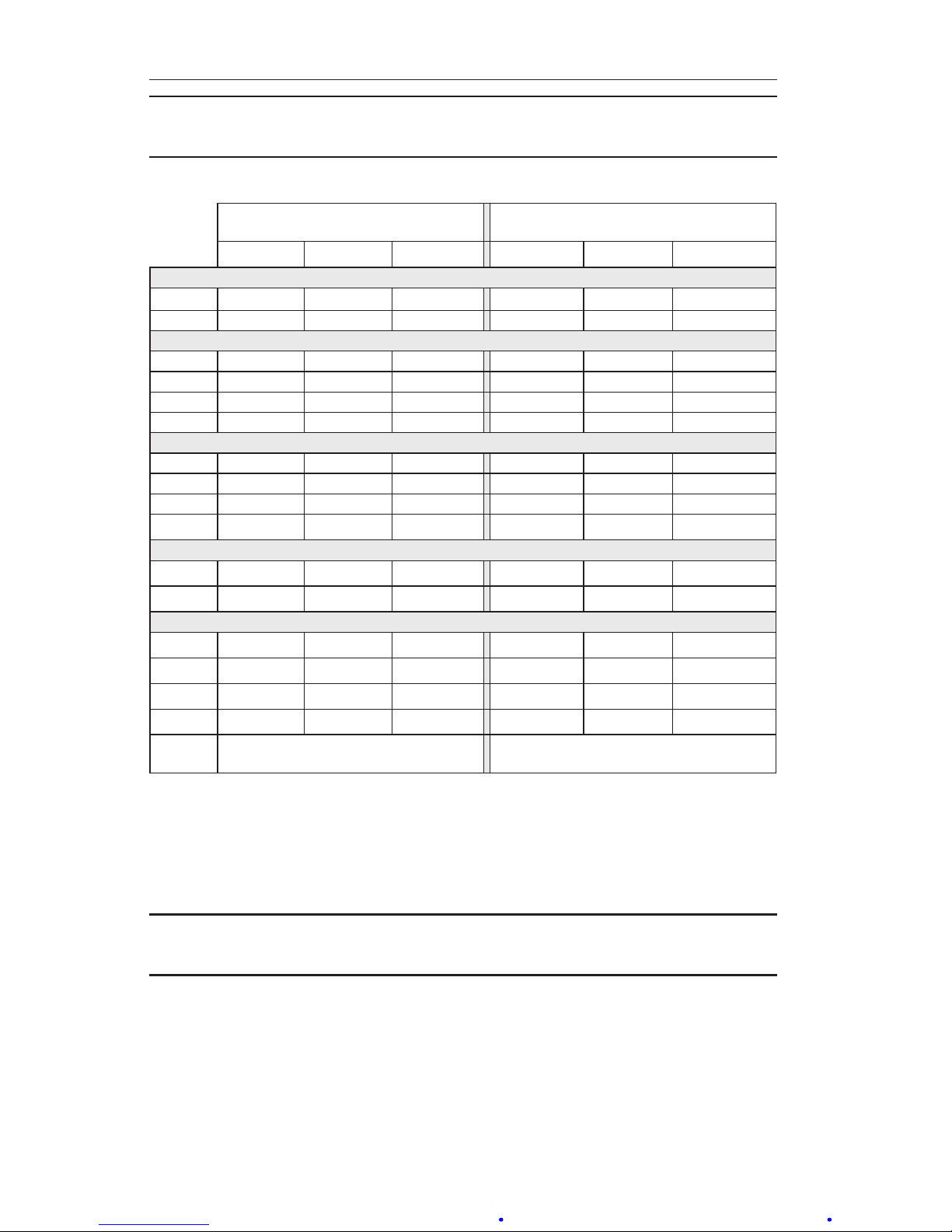
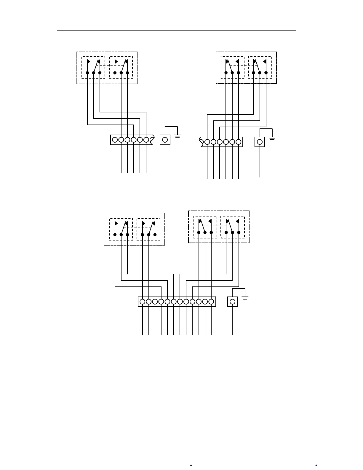
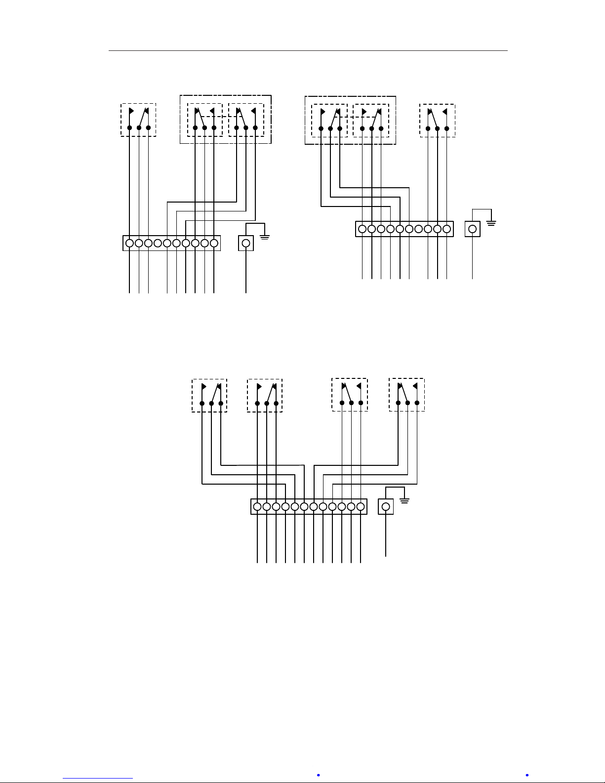
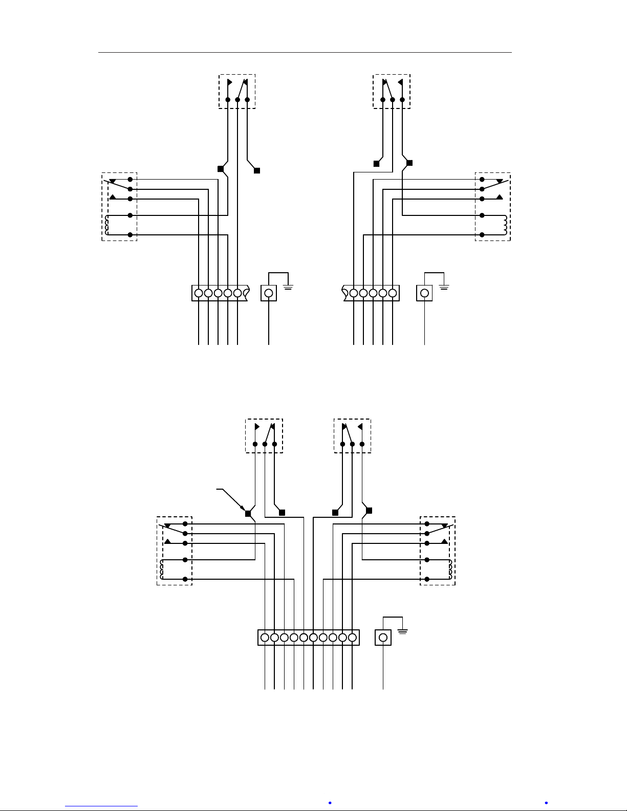
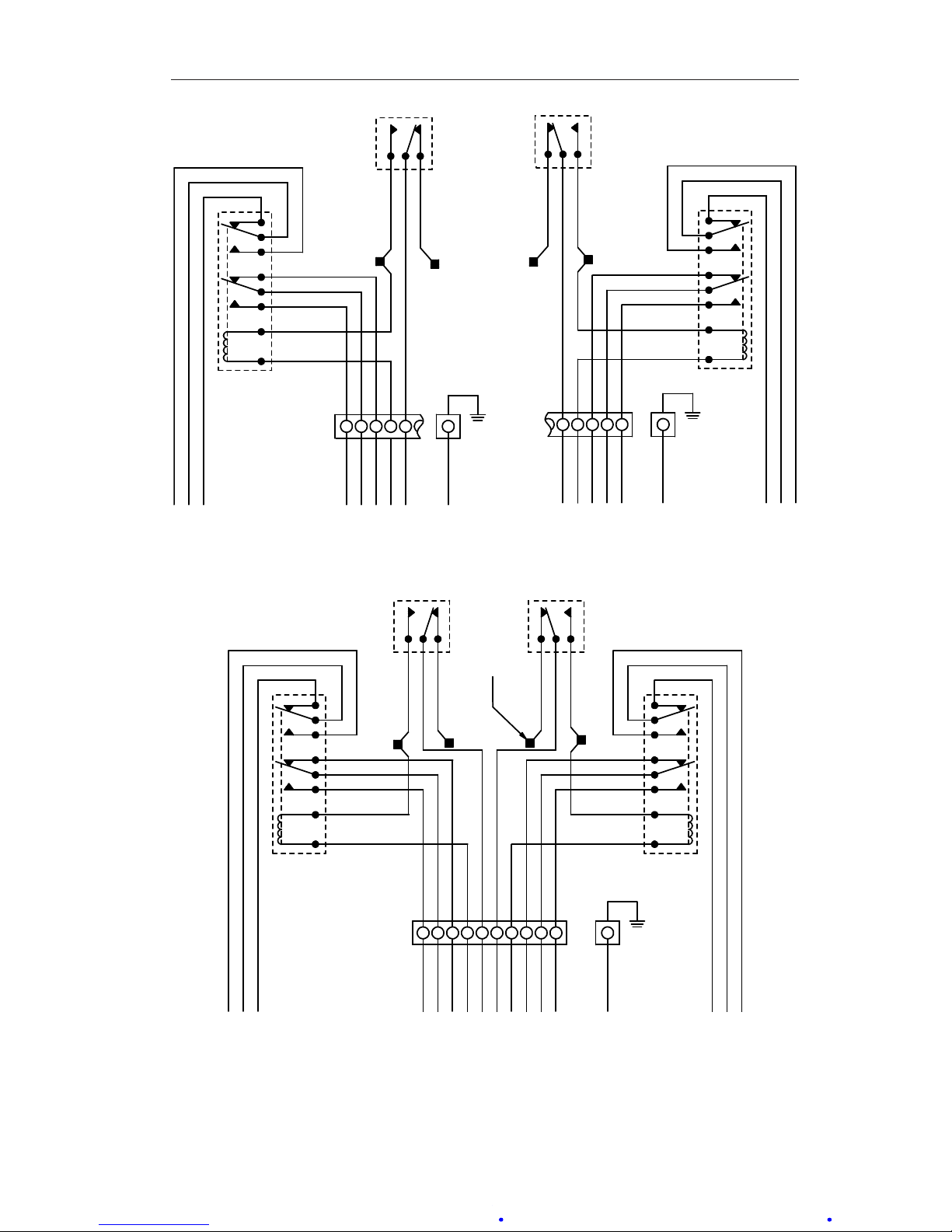
Table 2.1, page 8, shows switch and relay wiring color coding for legacy
and current congurations. Figures 2.1 through 2.6 show switch and relay
wiring.
The high switch and low switch set point adjustment procedures are covered
in Changing Switch Set Point, page 22.
For physical location of switches, see Figure 1.1, page 3.
SwitchUse
Switch contact life is inuenced by various application conditions such as
temperature, humidity, airborne contamination, vibration, amount of plunger
travel, cycling rate, and rate of plunger travel (and others), as well as by the
electrical (circuit) characteristics.
IMPORTANT: Arc suppression for inductive loads will prolong the life of the switch
contacts.
Page 8
8
Section 2 Model 289A Differential Pressure Indicating Switch
IMPORTANT: Due to their size, subminiature switches have small mechanical clear-
ances; therefore, no rating above 250 VAC has been established.
Table2.1—Switch/RelayWireColorCoding(4/06c)
289A LEGACY CONFIGURATIONS
(priortoApr.2006)
289A CURRENT CONFIGURATIONS
NO C NC NO C NC
SPDT SWITCHES
Low Red Yellow Blue Red Yellow Blue
High Black Green White Black Violet Orange
DPDT SWITCHES
Low #1 Red Yellow Blue Red Yellow Blue
Low #2 White/Red White/Yellow White/Blue White/Red White/Yellow White/Blue
High #1 Black Green White Black Violet Orange
High #2 White/Black White/Green White/Violet White/Black White/Violet White/Orange
4-INDEPENDENTLY ADJUSTABLE SWITCHES
Low #1 Red Yellow Blue Red Yellow Blue
Low #2 White/Red White/Yellow White/Blue White/Red White/Yellow White/Blue
High #1 Black Green White Black Violet Orange
High #2 White/Black White/Green White/Violet White/Black White/Violet White/Orange
SWITCHES FOR RELAYS
Low Red Yellow Blue (Note 1) White/Brown Brown White (Note 1)
High Black Green White (Note 1) White/Gray Gray White (Note 1)
RELAYS
Low #1 Gray Blue Brown Red Yellow Blue
Low #2 White/Gray White/Blue White/Brown White/Red White/Yellow White/Blue
High #1 Violet White Orange Black Violet Orange
High #2 White/Violet White/Black White/Orange White/Black White/Violet White/Orange
Coil
Wiring:
Legacy Ver.: Low = Red and High = Black Current Ver.: Low = White/Brown and High = White/
Gray
Note 1: Wire is NOT connected.
Startup
For startup procedures, warnings, and other information, refer to the Model
199 DPU user manual in Appendix A.
IMPORTANT: To ensure the unit calibration is within factory-set calibration tolerances,
perform the Calibration Check procedure on page 15.
Page 9
9
Model 289A Differential Pressure Indicating Switch Section 2
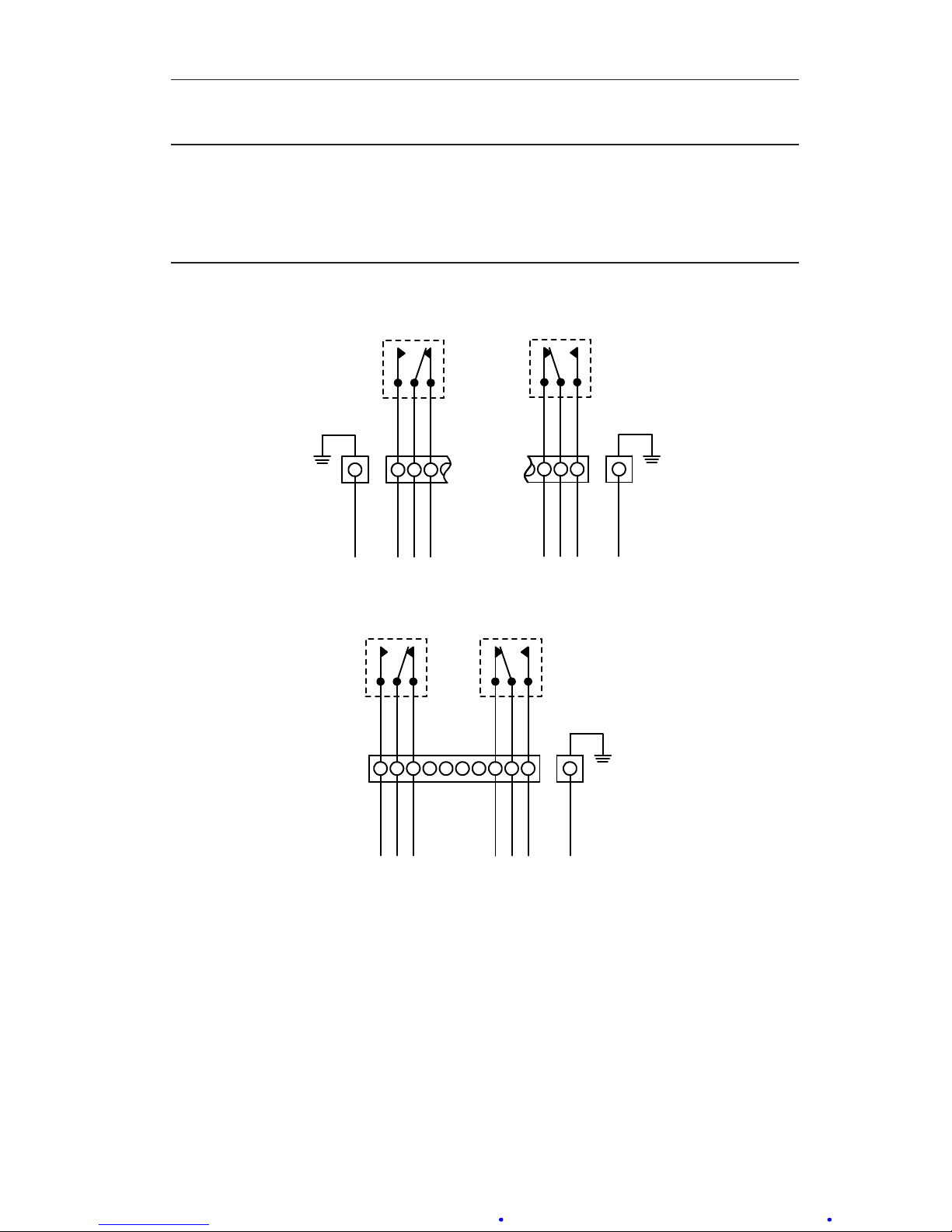
SwitchandRelayWiringDiagrams
IMPORTANT: Figures 2.1 through 2.6 show: switch & relay contacts in the relaxed
(shelf) condition, the low switch set to trip at a position below the pointer
scale position, and the high switch set to trip at a position above the
pointer scale position. NO = Normally Open in (shelf) condition. NC =
Normally Closed in (shelf) condition. C= Common.
HIGH SPDT SWITCH
NOCNC
CASE GROUND
GREEN
ORANGE
VIOLET
BLACK
ORANGE
VIOLET
BLACK
8 9 10
LOW SPDT SWITCH
NO
1
2 3
C NC
RED
YELLOW
BLUE
RED
CASE GROUND
GREEN
YELLOW
BLUE
LOW & HIGH SPDT SWITCHES
NO NOC CNC NC
RED
YELLOW
BLUE
RED
CASE GROUND
GREEN
YELLOW
BLUE
ORANGE
VIOLET
BLACK
ORANGE
VIOLET
BLACK
1 2 3 4 5 6 7 8 9 10
Figure 2.1—Low/high SPDT switch diagrams
(current conguration color codes - see Table 2.1, page 8)
Page 10
10
Section 2 Model 289A Differential Pressure Indicating Switch
HIGH DPDT SWITCH
NOCNC NOCNC
ORANGE
VIOLET
BLACK
ORANGE
CASE GROUND
GREEN
VIOLET
BLACK
WHITE/ORANGE
WHITE/VIOLET
WHITE/BLACK
WHITE/ORANGE
WHITE/VIOLET
WHITE/BLACK
5 6 7 8 9 10
LOW DPDT SWITCH
NO C NC NO C NC
RED
YELLOW
BLUE
RED
CASE GROUND
GREEN
YELLOW
BLUE
WHITE/RED
WHITE/YELLOW
WHITE/BLUE
WHITE/RED
WHITE/YELLOW
WHITE/BLUE
1 2 3 4 5 6
LOW & HIGH DPDT SWITCHES
NO C NC NO C NC
RED
YELLOW
BLUE
RED
CASE GROUND
GREEN
YELLOW
BLUE
WHITE/RED
WHITE/YELLOW
WHITE/BLUE
WHITE/RED
WHITE/YELLOW
WHITE/BLUE
1 2 3 4 5 6
NOCNC NOCNC
ORANGE
VIOLET
BLACK
ORANGE
VIOLET
BLACK
WHITE/ORANGE
WHITE/VIOLET
WHITE/BLACK
WHITE/ORANGE
WHITE/VIOLET
WHITE/BLACK
7 8 9 10 11 12
Figure 2.2—Low/high DPDT switch diagrams
(current conguration color codes - see Table 2.1, page 8)
Page 11
11
Model 289A Differential Pressure Indicating Switch Section 2
3-SWITCHES
SPDT LOW & DPDT HIGH
NO
1
2 3 4
C NC
RED
YELLOW
BLUE
RED
YELLOW
BLUE
NOCNC NOCNC
ORANGE
VIOLET
BLACK
ORANGE
CASE GROUND
GREEN
VIOLET
BLACK
WHITE/ORANGE
WHITE/VIOLET
WHITE/BLACK
WHITE/ORANGE
WHITE/VIOLET
WHITE/BLACK
5 6 7 8 9 10
3-SWITCHES
DPDT LOW & SPDT HIGH
NO C NC NO C NC
RED
YELLOW
BLUE
RED
YELLOW
BLUE
WHITE/RED
WHITE/YELLOW
WHITE/BLUE
WHITE/RED
WHITE/YELLOW
WHITE/BLUE
1 2 3 4 5 6 7
NOCNC
CASE GROUND
GREEN
ORANGE
VIOLET
BLACK
ORANGE
VIOLET
BLACK
8 9 10
Figure 2.3—3-switch diagram
(current conguration color codes - see Table 2.1, page 8)
4-SWITCHES
INDEPENDENTLY ADJUSTABLE
NO C NC NO C NC
RED
YELLOW
BLUE
RED
YELLOW
BLUE
WHITE/RED
WHITE/YELLOW
WHITE/BLUE
WHITE/RED
WHITE/YELLOW
WHITE/BLUE
1 2 3 4 5 6
NOCNC NOCNC
ORANGE
VIOLET
BLACK
ORANGE
CASE GROUND
GREEN
VIOLET
BLACK
WHITE/ORANGE
WHITE/VIOLET
WHITE/BLACK
WHITE/ORANGE
WHITE/VIOLET
WHITE/BLACK
7 8 9 10 11 12
Figure 2.4—4-switch diagram (3 or 4 independently adjustable switches)
(current conguration color codes - see Table 2.1, page 8)
Page 12
12
Section 2 Model 289A Differential Pressure Indicating Switch
HIGH SWITCH
WITH SPDT RELAY
NO
NO
6
7 8 9 10
CCNC
NC
BLACK
VIOLET
ORANGE
WHITE/GRAY
WHITE/GRAY
WHITE
GR AY
WHITE/GRAY
CASE GROUND
GREEN
VIOLET
BLACK
GR AY
WHITE/GRAY
ORANGE
LOW SWITCH
WITH SPDT RELAY
NO
NO
1
2 3 4 5
CCNC
NC
RED
YELLOW
BLUE
WHITE/BROWN
WHITE/BROWN
WHITE/BROWN
BROWN
WHITE/BROWN
BROWN
WHITE
RED
CASE GROUND
GREEN
YELLOW
BLUE
LOW & HIGH
SWITCHES WITH
SPDT RELAYS
NO
NO
1
2 3 4 567 8 9 10
CCNC
NC
RED
YELLOW
WIRE NUT (TYPICAL)
BLUE
WHITE/BROWN
WHITE/BROWN
WHITE/BROWN
BROWN
WHITE/BROWN
BROWN
WHITE
RED
CASE GROUND
GREEN
YELLOW
BLUE
NO
NO
CCNC
NC
BLACK
VIOLET
ORANGE
WHITE/GRAY
WHITE/GRAY
WHITE
GR AY
WHITE/GRAY
VIOLET
BLACK
GR AY
WHITE/GRAY
ORANGE
Figure 2.5—Low/high switch(es) w/SPDT relay(s) diagrams
(current conguration color codes - see Table 2.1, page 8)
Page 13
13
Model 289A Differential Pressure Indicating Switch Section 2
HIGH SWITCH
WITH DPDT RELAY
NO
6
7 8 9 10
C
NC
NO
C
NC
BLACK
VIOLET
ORANGE
WHITE/BLACK
WHITE/VIOLET
WHITE/ORANGE
WHITE/GRAY
WHITE/GRAY
VIOLET
WHITE
BLACK
GR AY
WHITE/GRAY
GR AY
CASE GROUND
GREEN
WHITE/GRAY
ORANGE
NO
C
NC
LOW SWITCH
WITH DPDT RELAY
NO
1
2 3 4 5
C
NC
NO
C
NC
RED
YELLOW
BLUE
WHITE/RED
WHITE/YELLOW
WHITE/BLUE
WHITE/BROWN
WHITE/BROWN
WHITE/BROWN
WHITE/BROWN
BROWN BROWN
WHITE
RED
CASE GROUND
GREEN
YELLOW
BLUE
NO C NC
NO
1
2 3 4 5
C
NC
NO
C
NC
RED
YELLOW
BLUE
WHITE/RED
WHITE/YELLOW
WHITE/BLUE
WHITE/BROWN
WHITE/BROWN
WHITE/BROWN
WHITE/BROWN
BROWN
BROWN
WHITE
RED
CASE GROUND
GREEN
YELLOW
BLUE
NO C NC
LOW & HIGH SWITCHES
WITH DPDT RELAYS
NO
6
7 8 9 10
C
NC
NO
C
NC
BLACK
VIOLET
ORANGE
WHITE/BLACK
WHITE/VIOLET
WHITE/ORANGE
WHITE/GRAY
WHITE/GRAY
VIOLET
WHITE
BLACK
GR AY
WHITE/GRAY
GR AY
WHITE/GRAY
ORANGE
NO
C
NC
WIRE NUT
(TYPICAL)
Figure 2.6—Low/high switch(es) w/DPDT relay(s) diagrams
(current conguration color codes - see Table 2.1, page 8)
Page 14

14
Section 3 Model 289A Differential Pressure Indicating Switch
Section 3—Maintenance and Calibration
The following checks are recommended for preventive maintenance:
• Periodically inspect alarm switch mechanism to verify that all mounting
screws are seated properly.
• Inspect linkage for wear.
• Inspect integrity of electrical circuits. Tighten as necessary.
When repairs are necesssary, review this section for maintenance procedures
such as bezel/lens installation and removal, pointer installation and removal,
indicator calibration, switch calibration, and switch set point changes.
IMPORTANT: DPU maintenance is not addressed in this manual. See the Model 199
DPU user manual in Appendix A for related warning/caution notices and
instructions on DPU inspection, cleaning, service, repair, range change,
and BUA replacement. Neverperformmaintenance/repaironthein-
strumentorDPUwithoutrstreviewingallproceduresandwarning/
caution notices in the DPU manual.
Tools
The following tools are recommended for general maintenance of the Model
289A DP indicating switch.
Table 3.1—Tools
Equipment Purpose
Pointer Puller Pointer removal
Small Screwdriver Calibration adjustment
Medium Screwdriver Bezel removal and replacement
1/4" and 1/8" Open-end Wrenches Zero (1/4") and Range (1/8") adjustments
1/8 Hex Allen Wrench Switch set point adjustment
3/32" Hex Allen Wrench Drive Arm Tightness Test
Bezel/Lens(orCover)InstallationandRemoval
To remove the bezel and lens (or cover), perform the following steps, using
Figure 3.1 for reference.
1. Loosen the three screws on the front of bezel.
2. Tilt the bottom of the bezel and slide the bezel upward.
To reinstall the bezel and lens, assemble the components per Figure 3.1,
page 15. The two snubbers (Part No. 9A-C0266-0028C) on the scale plate
should not be compressed against the lens cover and the pointer should not
touch the lens.
Page 15
15
Model 289A Differential Pressure Indicating Switch Section 3
Bezel
(9A-C0277-0029C)
Cover (Lens)
(9A-C0181-0038C)
Gasket
(9A-C0277-0026C)
Case
Figure 3.1—Bezel and lens cover
IMPORTANT: Ensure the bezel gasket is properly oriented before placing the instru-
ment back in service. Incorrect gasket orientation will cause the instrument indicator to jam, resulting in inaccurate readings.
Calibration Check
To ensure the unit calibration is within factory-set calibration tolerances,
perform the following procedure.
IMPORTANT: Review all procedures, WARNINGS/NOTICES in the Model 199 DPU
user manual (Appendix A) BEFORE performing this procedure.
HUB
Pointer "slipped"
rotated on hub
Hub held in place
with 1/4" wrench
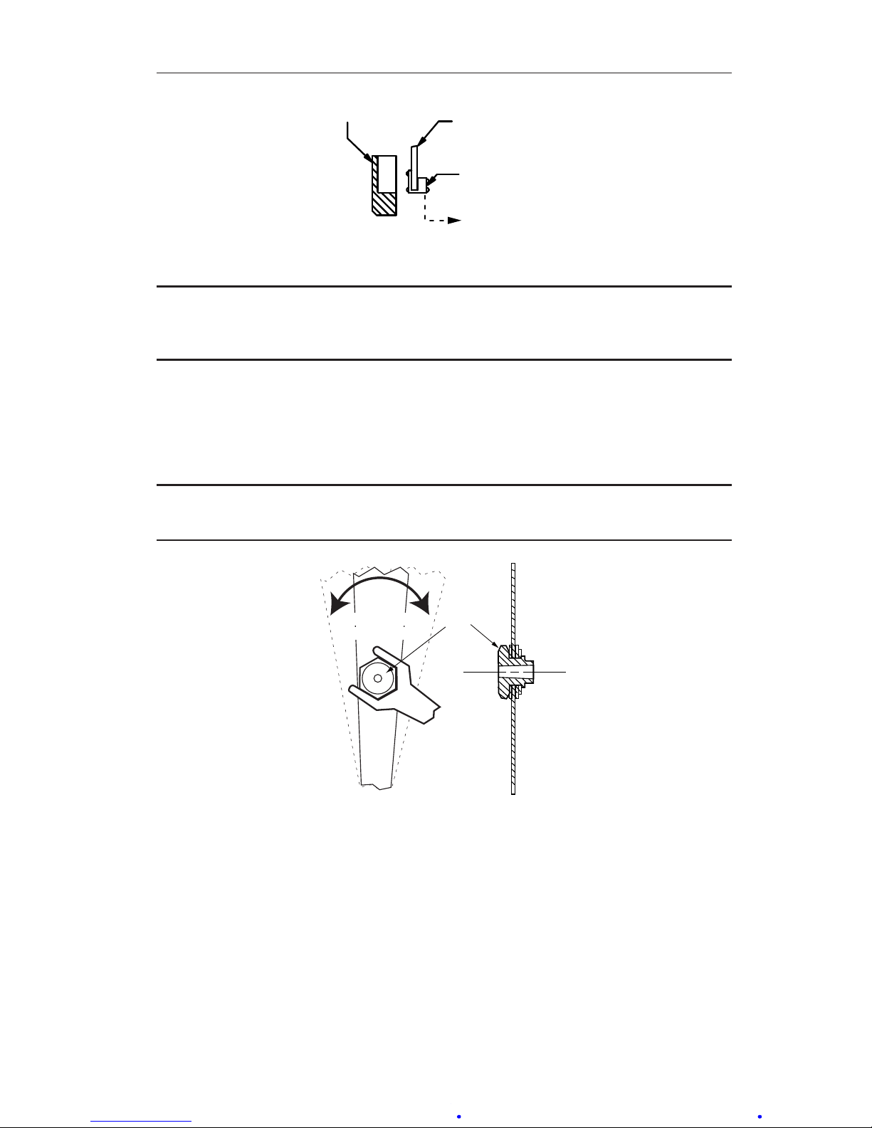
Figure 3.2—"Slipping" pointer
1. Mount the instrument in an approximately level position and connect to
a standard pressure source (see the Model 199 DPU user manual in Appendix A).
2. If the zero indication is incorrect, adjust it as follows:
a. Remove the bezel/lens assembly.
b. Using a 1/4" open-end wrench (included in calibration toolkit, Part
No. 9A-0288-1032B), hold the hexagon pointer hub xed and rotate
the pointer with ngers until the pointer indicates zero on the scale.
See Figure 3.2.
c. Replace the bezel/lens assembly.
Page 16

16
Section 3 Model 289A Differential Pressure Indicating Switch
3. To test for reverse travel, connect the pressure source to the LP housing
and vent the HP housing. Apply pressures approximately 150% of the DP
range. The pointer should move approximately 5% to 10% below zero.
4. To test for overtravel, connect the pressure source to the HP housing and
vent the LP housing. Apply pressures approximately 150% of DP range.
The pointer should move approximately 5% to 10% above full scale.
5. Apply 0, 50, and 100% of full scale pressure. If indication is within
specied limits, no adjustments are necessary. If indication is not within
specied limits, perform a complete calibration (see Indicator Calibra-
tion, page 17).
6. Make sure the instrument zero indication is correct; otherwise, repeat
step 2.
7. Verify the switch set points (refer to Changing Switch Set Point, page
22).
Pointer Installation and Removal
During adjustment and calibration of the unit, it may be necessary to remove
and reinstall the pointer according to the following procedures.
Pointer Installation
1. Position the pointer on the movement shaft with the pointer set at zero
scale. Obtain 75% to 90% pointer hub engagement on the movement
pinion shaft. The pinion shaft must not extend through the pointer hub.
It may be necessary to enlarge the hub hole, using a tapered broach (included in the calibration toolkit, Part No. 9A-0288-1032B).
2. Lightly tap the pointer hub with a hand-set or other at-end tool. Use
perpendicular blows to avoid bending the shaft.
3. Check the calibration of the indicating switch over its entire range (refer
to Indicator Calibration, page 17). If the indicating switch is correctly
calibrated, secure the pointer to the movement shaft by tapping the hub
with a hand-set or other at-end tool.
4. Test the pointer for tightness by moving the pointer from the zero to the
50% position manually, and then letting the pointer return freely to zero.
If the pointer indicates a shift, tap the pointer hub to tighten it to the
shaft.
Pointer Removal
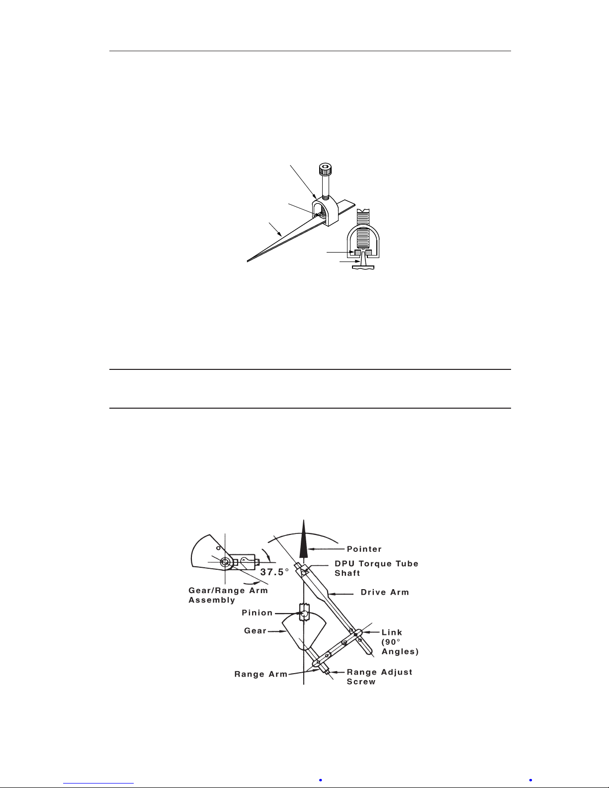
The pointer is removed with a pointer puller shown in Figure 3.3, page 17.
This tool is included in the calibration toolkit, Part No. 9A-0288-1032B.
To remove the pointer, perform the following steps:
1. Slide the pointer puller along the pointer until the pin protruding from the
tip of the screw in the pointer puller is directly over the movement shaft
and the arms of the pointer puller are directly under the pointer.
Page 17
17
Model 289A Differential Pressure Indicating Switch Section 3
2. Gently turn the knurled head of the screw clockwise, pushing the pin
against the movement shaft and lifting the pointer with the arms. Finger
pressure should be sufcient to pull the pointer free. If more pressure is
required, an Allen wrench (inserted into head of the screw) can be used.
However, care should be exercised to avoid breaking the pin.
HUB
MOVEMENT SHAFT
POINTER
HUB
POINTER PULLER
Figure 3.3—Pointer puller (Part No. 9A-0163-0005B)
Indicator Calibration
A complete calibration of instrument is required whenever the DPU assembly
is replaced.
IMPORTANT: Review all procedures, WARNINGS/NOTICES in the Model 199 DPU
user manual (Appendix A) BEFORE performing this procedure.
1. Securely mount the instrument in an approximately level position and
connect the DPU (see the Model 199 DPU user manual in Appendix A).
2. Remove the bezel/lens assembly.
3. Align the linkage between the drive arm and the movement at 50% differential pressure (DP) as shown in Figure 3.4. Inspect parts for straightness
and pivot-t without binding.
Figure 3.4—Range/linearity adjustment (50% DP)
Page 18
18
Section 3 Model 289A Differential Pressure Indicating Switch
4. Check the pointer for zero indication. If necessary, set the pointer to zero
by slipping the pointer on the hub, per Calibration Check, step 2, page
15.
5. Apply 100% pressure. If the pointer exceeds full-scale, lengthen the
movement range arm by adjusting the range adjust screw with a 1/8-in.
open-end wrench.
6. Release pressure. Set the pointer to zero, by slipping the pointer on the
hub, per Calibration Check, step 2, page 15.
7. Repeat steps 4 and 5, as necessary, to obtain the correct zero/full-scale.
8. Apply 50% DP. If the pointer indicates 50%, proceed to step 9. If the
pointer does not indicate 50% scale, adjust linearity as follows.
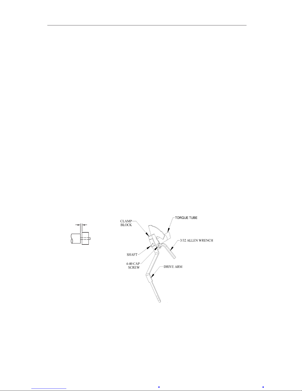
a. Loosen the drive arm screw (Figure 3.5) and move the arm to shift
the pointer in the direction of the error a distance of about 10 times
the linearity error.
b. Check to see that the drive arm clears the end of torque-tube housing
by approximately 0.030 in. before retightening the drive arm screw
to prevent interference.
c. While supporting the block/shaft, tighten clamp screw until snug to
shaft.
d. Still supporting block/shaft, tighten clamp screw an additional 1/3
to 1/2 turn. (This screw can normally turn one full revolution before
breaking.)
e. Perform the Drive Arm Tightness Test described on page 19.
1/8” WRENCH
(PN 9A-0163-0044C)
CLAMP SCREW
DRIVE ARM
LINK
SINTERED
CLAMP BLOCK
TO TIGHTEN
.03 (approx)
M224
SHAFT
Figure 3.5—Drive arm to torque tube connection
9. Release pressure and reset the pointer at zero. Check the span. If the gear
in the movement reaches a limit of travel as a result of linearity adjustment (step 7), slip the range arm along the gear approximately 5 degrees
from the normal 37.5 degree angle to approximately 43 degrees (see step
2). The range arm is slipped by applying pressure to the range arm with
Page 19

19
Model 289A Differential Pressure Indicating Switch Section 3
thumb, while holding the gear rmly in place. Retest the pointer response
at 50%, 0%, and 100% of full-scale differential pressure, and adjust the
linkage until the readings are acceptable.
10. Apply 0%, 25%, 50%, 75%, 100%, 75%, 50%, 25%, and 0% of full-scale
differential pressure consecutively to the instrument without overshoot.
Lightly tap the indicator to overcome friction. The pointer should accurately indicate each applied pressure.
11. Test the instrument repeatability by applying 0%, 50%, 0%, 50% of fullscale differential pressure. The indicator should accurately indicate each
applied pressure.
12. Set the drive arm stop to prevent the pointer from striking the snubbers
on the scale. (See Drive Arm Stop Adjustment, page 20.)
13. Test the pointer for tightness per the pointer installation instructions on
page 16.
14. If the drive arm screw has been loosened, verify that it is adequately tight
by performing the Drive Arm Tightness Test described below.
15. Reassemble the unit per the cover installation instructions on page 14.
Drive Arm Tightness Test
This procedure tests the tightness of the drive arm's connection to the torque
tube by applying torque developed by the DPU onto a xed drive arm. Care
should be taken to apply pressure slowly, as torque is being applied to the
connection through the torque tube drive shaft.
1. With the pointer at normal 0% torque tube rotation position (0% on a
normal 0 to 100% scale unit), adjust the drive arm stop bracket (or use
alternate means) to prevent the pointer from moving (stop bracket interferes with drive arm movement).
IMPORTANT: On reverse acting/split range units, it will be necessary to pressurize the
DPU to move the pointer to maximum minimum scale position, and on
suppressed units, it will be necessary to apply pressure to establish a
reference point to check for "zero" shift.
2. Pressurize the DPU to full calibrated scale DP (100% of full scale range)
to achieve 8 degrees of torque tube equivalent torque onto the connection.
3. Observe the shift in the unit "zero" following DPU depressurization (as
required) and drive arm stop bracket readjusting (to allow free movement of drive arm and pointer). A downscale (counter-clockwise) shift in
"zero" of greater than 1/2% is indicative of drive arm slippage, necessitating further clamp block tightening.
Page 20
20
Section 3 Model 289A Differential Pressure Indicating Switch
Drive Arm Stop Adjustment
1. Apply sufcient pressure to the high-pressure housing to deect the
pointer against the full range stop snubber on the scale plate.
2. Slide the upper drive arm stop bracket against the drive arm and tighten
the drive arm stop bracket screw.
3. Apply sufcient pressure to the low pressure housing to deect the
pointer against the zero stop snubber on the scale plate.
4. Bend the zero drive arm stop against the drive arm.
5. Verify calibration as applicable.
SwitchCalibration
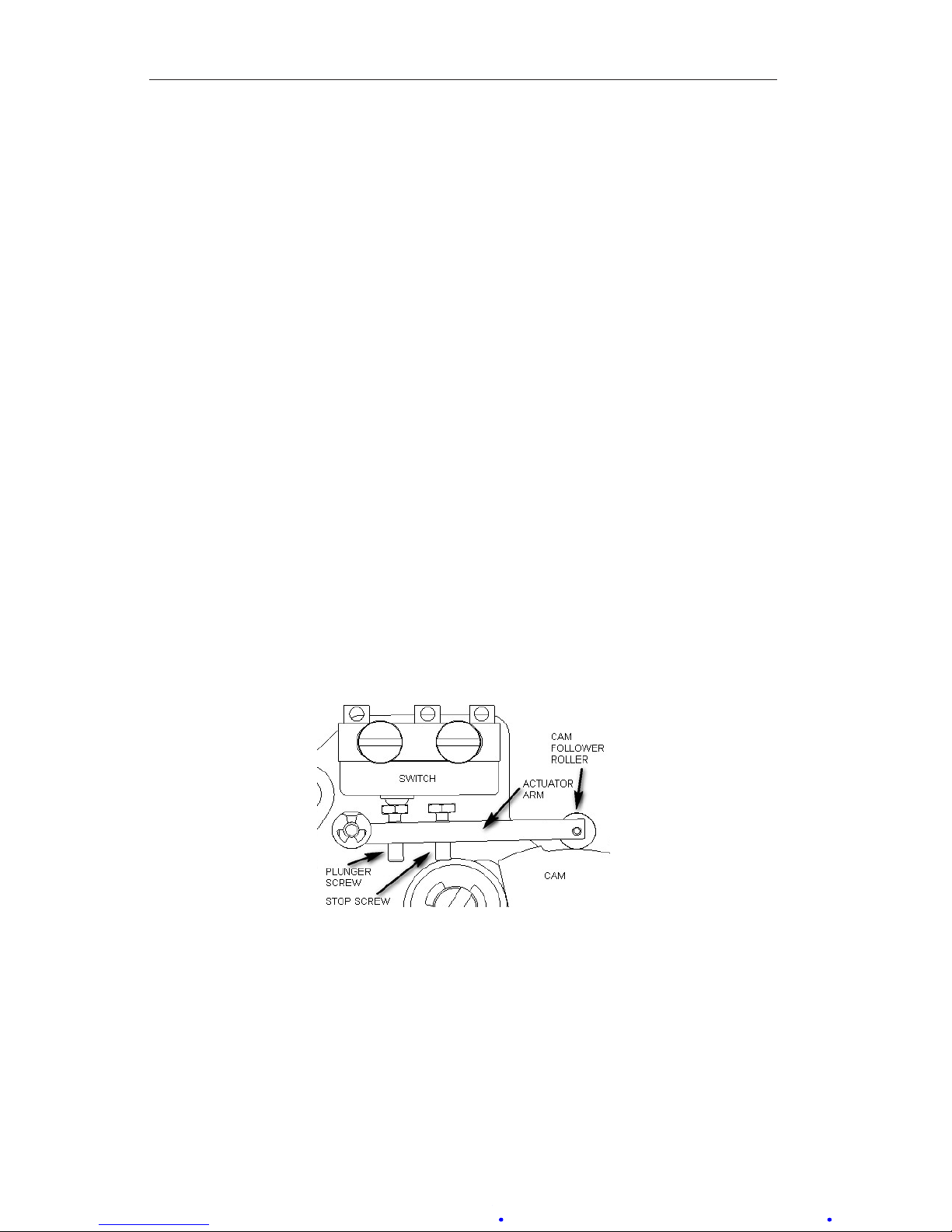
Before performing a complete calibration procedure, verify that the instrument is out of calibration, by performing a calibration check procedure (page
15). If the instrument is out of calibration, before performing a complete
calibration procedure, remove the bezel/lens and scale plate and inspect the
switch mechanism (Figure 3.6) to verify the following:
• The roller rotates without wobble or binding.
• The cam is relatively centered under the roller.
• The actuator arm moves freely on its pivot.
• All switch mounting screws are tight.
• Linkages are straight and do not bind at the pivots.
Correct any problems that are observed.
Figure 3.6—Switch mechanism
Calibration Setup
1. Connect the lamp or buzzer to the switch output leads.
2. Connect a test voltage to the switch input terminals on the terminal strip.
(A low voltage is recommended for safety.) If a relay is installed in the
instrument, coil voltage must be applied to the switch.
3. Unlock the switch plate and move the plate until the roller is positioned
at the top of the cam.
Page 21
21
Model 289A Differential Pressure Indicating Switch Section 3
4. Advance the plunger screw until the switch actuates, then advance the
plunger screw an additional 60° (one at).
5. Exercise the switch roller up and down the cam to verify consistent on/
off operation. Advance the stop screw to touch the switch, then back out
the screw 1.5 turns (9 ats).
Calibration Procedure
To calibrate the switch linkage (required when the unit is rebuilt), perform the
following steps. Refer to Figure 3.7 as needed.
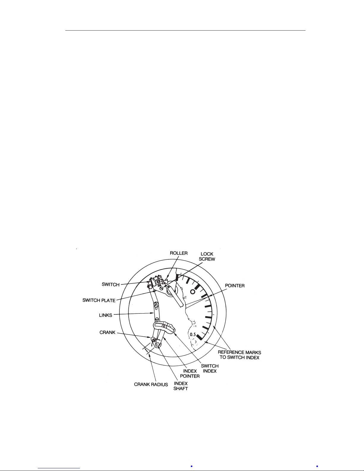
1. Loosen the three linkage screws and turn the crank to the 12 o’clock
position.
2. Use a 1/8-inch Allen wrench to hold the index shaft and slip the index
pointer to 0 on the switch index. Tighten the screw on the crank to the
mid-slot position.
3. Turn the switch index pointer to “1” (index numbers refer to numbers on
outer edge of scale plate).
4. Apply 10% differential pressure and adjust the switch plate until the
switch actuates. Lock the two linkage screws.
5. Rotate the index pointer to “9.” Apply 90% differential pressure and
adjust the crank radius until the switch actuates.
6. Recheck 10% and 90% set points. Adjust the crank radius and the index
pointer until both set points are 2% accurate (nominal).
Figure 3.7—Linkage arrangement
Page 22

22
Section 3 Model 289A Differential Pressure Indicating Switch
7. If the switch is to be eld-set at low differential pressure values (1% or
2% of pressure range), check the crank to prevent a top-dead-center position. Otherwise, the minimum set point position will be restricted and the
set point may become reversed.
8. Adjust the switch to actuate at the desired pressure by applying test pressures in a decreasing direction, in discrete steps. Allow the unit and the
pressure system to stabilize. Then change the pressure by a small amount.
The magnitude of the pressure change is determined by the desired
accuracy of the test. Tighten the lock screw before testing the switch
performance.
IMPORTANT: The high switch is usually set to actuate at increasing pressure — when
calibrating the high switch, apply test pressure in an increasing direction.
This amount of loading will prevent cam-runout of a similar condition.
IMPORTANT: Excessive plunger loading (more than 3 ats) may cause the roller to
drag on the cam. Cam friction will be apparent by excessive hysteresis,
erratic pointer readings and inconsistent switch operation.
9. Check the switch deadband, (actuate to reset) by applying differential
pressure, rst in a decreasing direction, then in an increasing direction
(opposite for high switch direction). Observe pressures. To reduce dead-
band, advance the plunger screw (two ats maximum).
10. Adjust the high switch to actuate at the desired pressure. The procedure is
the same as for the low switch.
ChangingSwitchSetPoint
(Tools: Screwdriver, 1/8-in. hex Allen wrench)
Denitions of Terms
Set Point. The measured pressure at which the snap-switch actuates and
thereby changes the states of the N.O and N.C. contacts. For example, the set
point of the low switch is 24 psid with decreasing pressure.
Deadband. The difference in measured pressures between switch-actuation
and switch-reset. Deadband is usually expressed as percent of full scale (%
of F.S.). Deadband is not adjustable. For example, the switch in the set point
example above was found to reset at 26.4 psid with increasing pressure. The
deadband was 2.4 psi, or 4% of the full scale for a unit calibrated 0 to 60 psid.
Best Practices for Set Points
1. Always check the set point after tightening switch lock screws.
2. Switch setpoints may be set at any point of the scale range, except in a
location that will prevent the deadband from enabling the switch to reset
Page 23
23
Model 289A Differential Pressure Indicating Switch Section 3
itself. For example, the high switch (right side of scale) may be set at
full scale, but should not be set near zero. The low switch may be set at
zero, but should not be set near full scale. (Observe deadband values for
specic models).
3. If switch performance is unsatisfactory (set point does not repeat, deadband is excessive, pointer exhibits hysteresis, contacts are unstable, etc.),
remove the scale and inspect the switch and the switch mechanism. The
scale is split to allow for removal without pulling the pointer.
Changing Set Point of an In-Service Instrument (Not Recommended for
Nuclear Qualied Units)
Use the following procedure to set a set point for an instrument that is in ser-
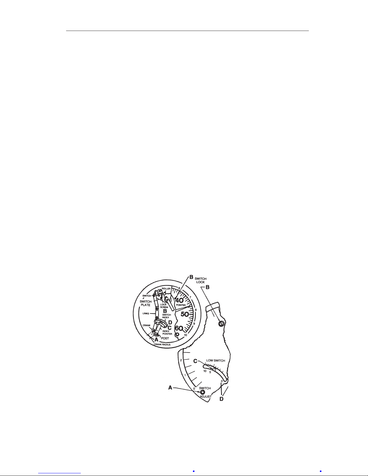
vice, when calibration pressures cannot be applied. See Figure 3.8 for specic
locations denoted by items A, B, C and D.
1. Remove the bezel/cover. Do not remove the pointer or scale.
2. Insert hex wrench in the switch adjust post.
3. Loosen the switch lock-screw, (item B), 1/2 to 1 turn.
4. With a hex wrench, move the index pointer (item C) to the new set point
as indicated on the switch index (item D).
5. If possible, check the set point by varying the process pressures and
observing the pointer readings when the switch actuates. (Open the manifold bypass valve slowly and watch for “pointer-jump” at the set point or
by electrical signal.) Adjust the setting, if necessary, and repeat the test
several times to verify stability.
Figure 3.8—Set point adjustment
Page 24

24
Section 3 Model 289A Differential Pressure Indicating Switch
IMPORTANT: The switch index has 10 divisions, marked 0, 5, and 10. These match the
markings on the outer edge of the scale.
Example: Scale has range of 0-60 psid. Set point is 24 psid, with decreasing
pressure, (24/60 x 10 = 4).
1. Move the index pointer (item C) for the low switch from division 0 to
division 4.
2. Tighten switch lock (Item B) snug plus 1/4 turn to place the set point
within ±2% of full scale. Do not overtighten.
3. Repeat step 1 for the high switch, moving the index pointer from division
10 to division 4, and tighten the switch lock as described in step 2.
Changing Set Point of an Out-of-Service Instrument
Use the following procedure to set a set point for an instrument that is out of
service—typically, an instrument that is disconnected from process lines or
mounted on a bench.
1. Drain and vent housings.
2. Attach the calibration pressure source (air or N2) to the DPU HP housing.
3. Apply varying pressures and observe pointer readings for accuracy. Use a
pressure standard (Heise gage or equiv.) for reference. Change pressures
slowly in discrete steps. A “bleed-pressure” method may cause errors.
4. Change switch set point as described in In-Service Instruments, page 23.
5. Check the set point by changing measured pressure to actuate the switch.
For example: To verify a low-switch set point of 24 psid, apply approximately 30 psi. Reduce pressure to approximately 25 psid, hold for a few
seconds, then continue in 1/4 psid steps until the switch actuates. If the
set point is incorrect, continue instructions in In-Service Instruments,
page 23.
6. To measure the switch deadband, reduce the pressure to zero, then increase pressure until the switch resets.
7. To verify repeatability of a set point, repeat step 5 several times. For
improved accuracy, use smaller increments of pressure. Allow extra time
for slow response gages and for test systems that have long runs of smallbore tubing.
High alarm switches (right side of the scale) are adjusted in a similar manner.
Apply increasing pressure to establish the switch set point, and apply decreasing pressure to measure the deadband.
Range Changes
Changing the range of a Model 289A differential pressure indicating switch
typically requires replacment of the 199 DPU.
Page 25

25
Model 289A Differential Pressure Indicating Switch Section 3
PartsReplacement
Due to the new snap-acting microswitch being used in Model 289A differential pressure indicating switch, the Drive Arm and Switch & Plate Assemblies
have been redesigned. These assemblies are not backwards compatible and
have to be installed at the same time for proper operation of the Model 289A.
Drive Arm and Switch & Plate Assemblies
1. Remove the bezel/cover per Bezel/Lens (or Cover) Installation and Removal, page 15.
2. Remove pointer (see Pointer Installation and Removal, page 17)
3. Remove scale plate by removing (4) Mounting Screws (see Figure 4.1).
4. Disconnect the Link from the original Drive Arm Assembly (see Figure
3.4).*
5. Loosen the Clamp Screw using 1/8” Open-end Wrench (for old style
Drive Arm) or 3/32” Hex Allen Wrench (for new style Drive Arm).*
6. Carefully move the Actuator Arms away from the Cam and slide the
Drive Arm Assembly off the Torque Tube.*
7. Disconnect the switch leads from the Terminal Block.
8. Carefully remove the Grip Ring and Washer securing the Drive/Link
Plate assembly from the Switch and Plate Assembly and save for the
installation process.
9. Remove the Lock Screw securing the high side Switch and Plate Assem-
bly rst and uninstall the Switch and Plate Assembly. Repeat for the low
side assembly.
10. Install and secure the replacement Switch and Plate Assemblies in the
reverse order above.
11. Install the replacement Drive Arm Assembly and ensure that the cam is
relatively centered under the cam rollers. Tighten the Clamp Screw using
3/32” Hex Allen Wrench.*
12. Reconnect the switch leads to the Terminal Block.
13. Calibrate the switches per Calibration Procedure, page 21.
*Note: These steps may be omitted if the Model 289A is already
equipped with the new Drive Arm and Switch & Plate Assemblies.
Page 26
26
Section 3 Model 289A Differential Pressure Indicating Switch
Troubleshooting
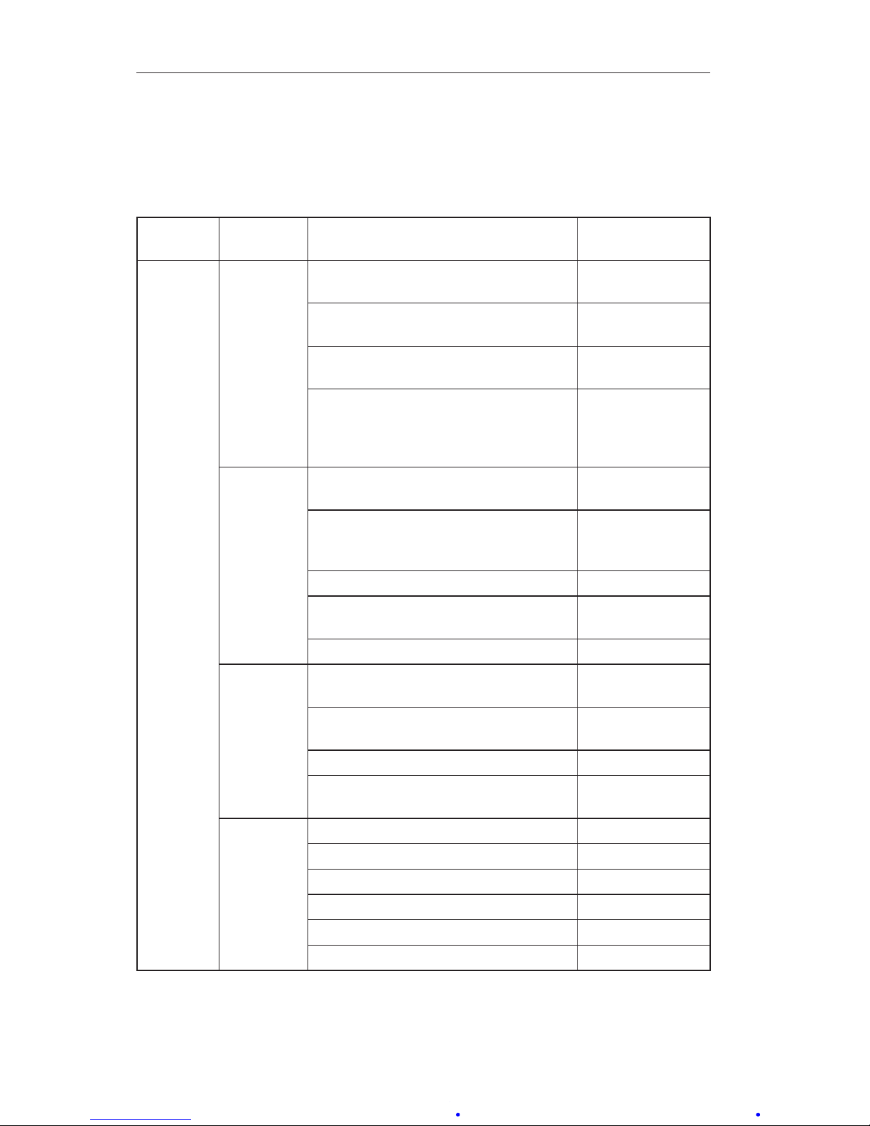
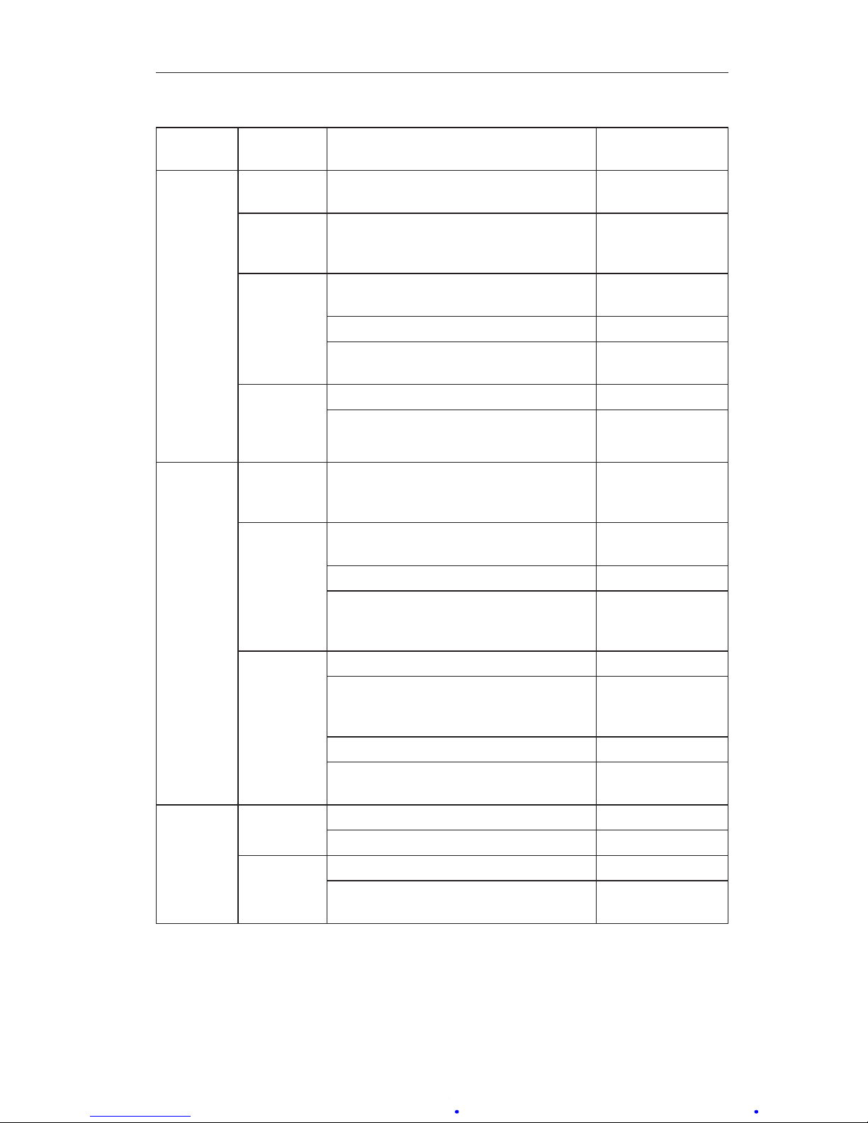
For troubleshooting tips, see Table 3.2 below. For information related to the
DPU, see the Model 199 DPU user manual in Appendix A.
Table3.2—Troubleshooting
Problem Possible
Source
Probable Cause Corrective
Action
Low or No
Indication
Primary
Element or
DPU
(Refer
to DPU
Manual)
Orice installed backwards or over
-
sized
Replace orice
Flow blocked upstream from run Clean out run or
open valve
Loss of liquid in reference leg (liquid
level)
Rell reference
leg
Density changes in process media or
reference leg
Rell reference
leg with same
density liquid as
process media
Primary
Element
to DPU
Piping
(Refer
to DPU
Manual)
Pressure tap holes plugged and/or
piping plugged
Clean out piping
Bypass valve open or leaking Close bypass
valve(s) and/or
repair leaks
Liquids or gases trapped in piping Vent piping
Block or shutoff valves closed Open block or
shutoff valves
Piping leaks on HP side Repair leaks
Bellows
Unit
(Refer
to DPU
Manual)
Housing lled with solids restricting
bellows movement
Clean out housing
Gas (liquid service) or liquid (gas service) trapped in housing
Vent housing
HP housing gasket leak Replace gasket
DPU tampered with Return BUA for
repair
Indicator, Alarm
Switch
Mechanism
Loose linkage or movement Tighten or replace
Out of calibration Calibrate
Pointer loose Tighten pointer
Dirty or corroded mechanism Clean or replace
Wiring interfering with movement Re-route wiring
Dirty mechanism
Clean mechanism
Page 27
27
Model 289A Differential Pressure Indicating Switch Section 3
Table3.2—Troubleshooting
Problem Possible
Source
Probable Cause Corrective
Action
High
Indication
Primary
Source
Orice partially restricted or too small Clean out or
replace
Primary
Element to
DPU piping
Piping leaks on LP side Repair leaks
Bellows
Unit (Refer
to DPU
Manual)
Gas (liquid service) or liquid (gas service) trapped in housing
Vent housing
LP housing gasket leak Replace gasket
Range spring broken or DPU tampered
with
Return BUA for
repair
Indicator,
AlarmSwitch
Mechanism
Loose linkage or movement
Tighten or replace
Out of calibration Calibrate
Erratic
Indication
Primary
Element
Flow pulsating Install dampening
device upstream
of DPU run
Primary
Element to
DPU piping
Liquid (gas service) or gas bubble
(liquid service) trapped in piping
Remove
Vapor generator incorrectly installed Re-pipe
Reference leg gassy or liquid vapor
-
izing
See piping
instructions in
DPU Manual
Bellows
Unit
(Refer
to DPU
Manual)
Obstructed bellows travel Clean bellows
Gas trapped in DPU HP or LP housing Remove (see
startup procedure)
Linkage dragging or dirty Adjust or clean
Pointer dragging on scale plate Adjust pointer
position
Inaccurate or No
Electrical
Alarm
Power
Supply
Blown fuse Replace fuse
Broken or loose wire Repair
Alarm
Switch
Switch not properly adjusted Adjust switch
Dirty or burned Replace switch
contacts
Page 28

28
Section 3 Model 289A Differential Pressure Indicating Switch
Table3.2—Troubleshooting
Problem Possible
Source
Probable Cause Corrective
Action
Switch
Drifts
(set
point not
repeatable)
Process
Changes
Transients or surges cause switches to
actuate prematurely
Add time delay
gages or add time
circuit
Set point and/or deadband are too
wide in pressure valves
Specify DP range
as low as practical; set point
repeatability and
deadband are
percentage of full
range
Electrical overloads affect the spring
properties of the leaf actuator in the
switch
Examine circuits
for voltage,
amperes
DC inductive loads cause arcing and
burning of contacts
Consider arc-suppression devices
or relays
Accumulation of uids in piping generate articial signal
Vent gas or drain
liquids from signal
lines
Calibration
Techniques
Failure to check set point after locking
Verify set point
repeatability after
locking switch
plate
Rapid pressure change or venting
system
During calibration,
make pressure
changes in slow,
discrete steps
Pressure application in reverse Test low-alarm
with decreasing
pressure and
high-alarm with
increasing pressure
Reference gage inaccuracy Suitable pressure
standard such
as manometer, dead-weight
tester, or Heisetype gage may be
required
Damage to switch contacts Adjust plunger
screws carefully
to avoid damage
to internal parts of
switch
Page 29
29
Section 4 Model 289A Differential Pressure Indicating Switch
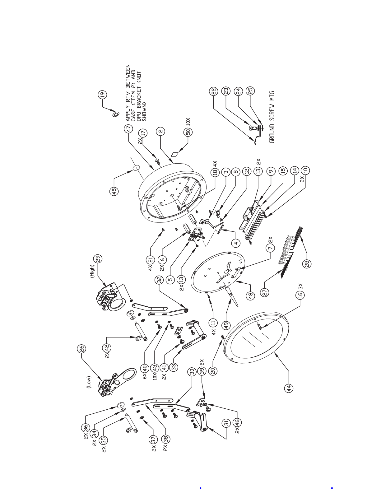
Section4—AssemblyDrawingandPartsLists
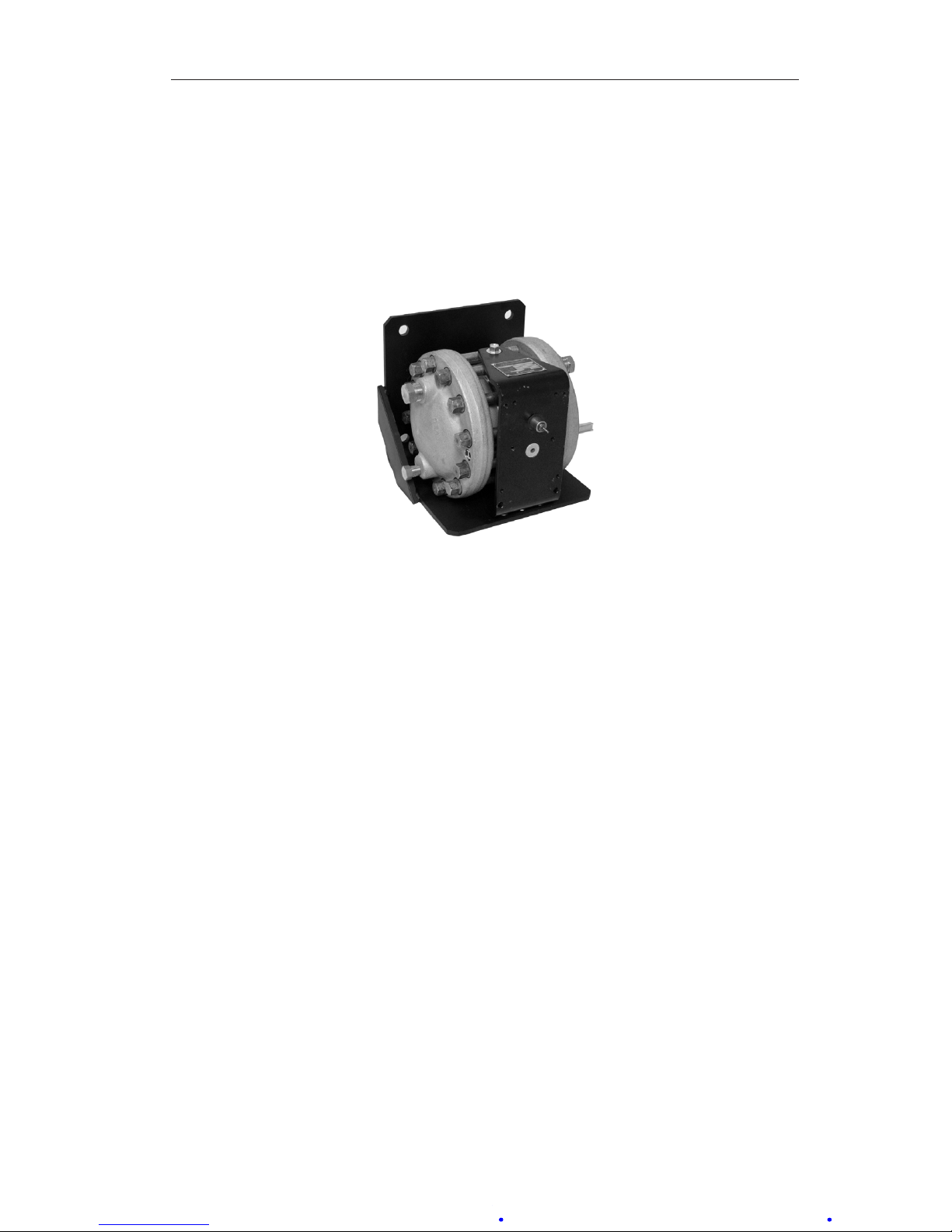
Figure 4.1—Model 289A
Page 30
30
Section 4 Model 289A Differential Pressure Indicating Switch
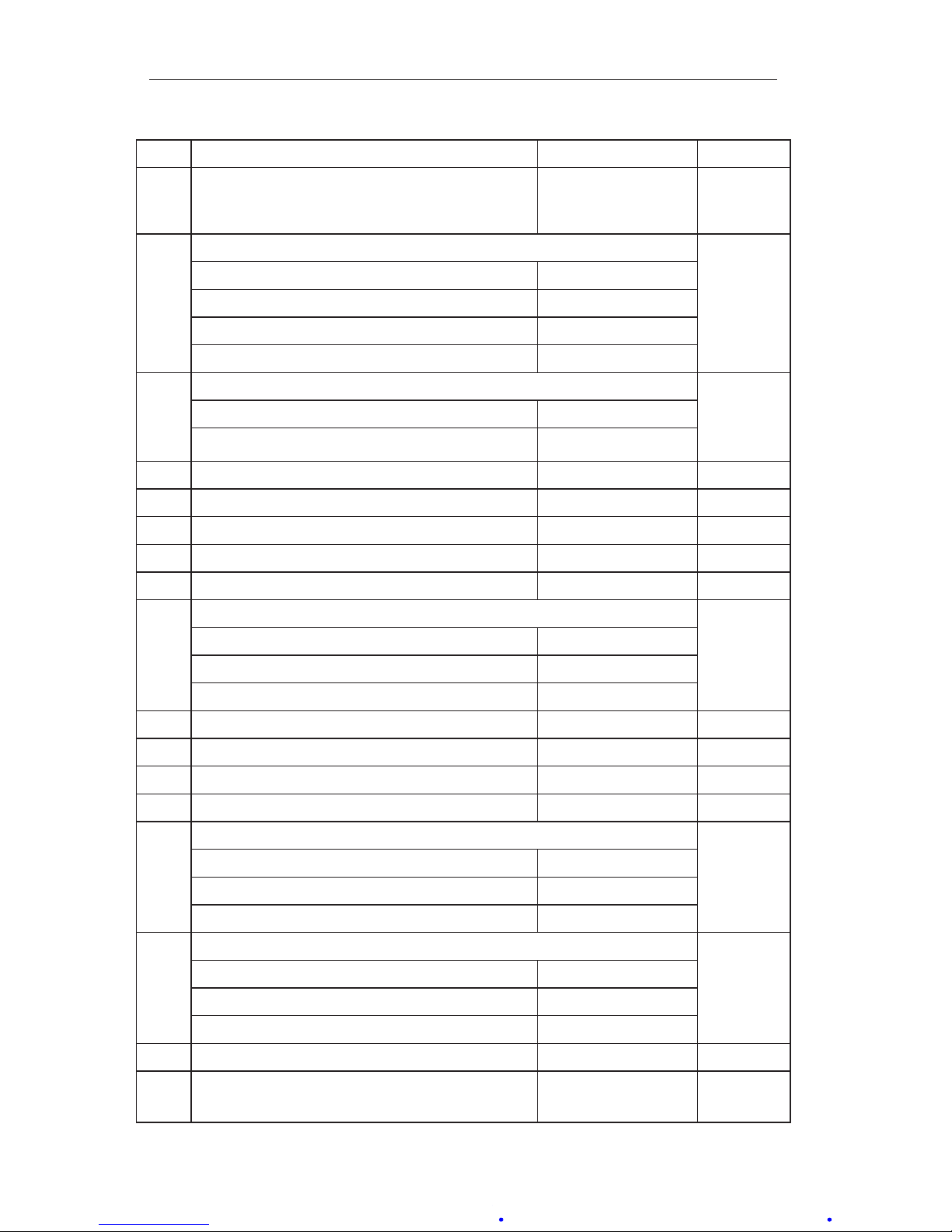
Table4.1—PartsList,Model289AIndicatingSwitch
Item Description Part No. Per Unit
1 Differential Pressure Unit (not shown) See Model 199
DPU User Manual
in Appendix A
1
2 Case Assembly 1
1/2 NPT Conduit, 1 & 2 Switches 9A-C0289-0003B
3/4 NPT Conduit, 1 & 2 Switches 9A-CS666-0051Z
1/2 NPT Conduit, 3 & 4 Switches 9A-CS469-0017Z
3/4 NPT Conduit, 3 & 4 Switches 9A-CS469-0078B
3 Drive Arm Assembly 1
Drive Arm Assembly, 1 & 2 Switches 9A-C0288-1204B-N
Drive Arm Assembly, 3 & 4 Switches 9A-CS469-1007B-N
4 Link Assembly 9A-C0288-0036B 1
5 Movement Assembly 9A-C0288-0035B 1
6 Movement Riser 9A-C0277-0035C 2
7 Snubber 9A-C0226-0028C 2
8 Stop Bracket 9A-C0288-0028C 1
9 Bracket, Terminal Block 1
10-Position (Standard) 9A-C0288-0029C
10-Position (For 14 AWG Terminal Blocks) 9A-C0288-1161C
12-Position 9A-CS469-0060Z
10 Screw, Rd Hd, 6-32 x 3/8, BRS, NP 9A-C0111-0015J 2
11 Screw, Sl Fil., Hd., 4-40 X 3/16, SST 9A-C0114-0023J 4
12 Screw, Bd Hd, 4-40 x 3/16, SST 9A-C0117-0012J 1
13 Screw, Bd Hd, 6-32 x 3/16, SST 9A-C0117-0013J 4
14 Terminal Block 1
10-Position (Standard) 9A-C0038-0033T
10-Position, 14 AWG 9A-C0288-1160C
12-Position 9A-CS469-0061Z
15 Strip, Insulator 1
10-Position (Standard) 9A-C0038-1345T
10-Position (For 14 AWG Terminal Blocks) 9A-C0038-1379T
12-Position 9A-C0038-1351T
16 Screw, Bezel 9A-C0181-0007C 3
17 Screw, Flat, Skt Cap, 10-32 x 1/2, SST (Riser/
DPU)
9A-C0240-0019J 2
Page 31
31
Model 289A Differential Pressure Indicating Switch Section 4
Table4.1—PartsList,Model289AIndicatingSwitch
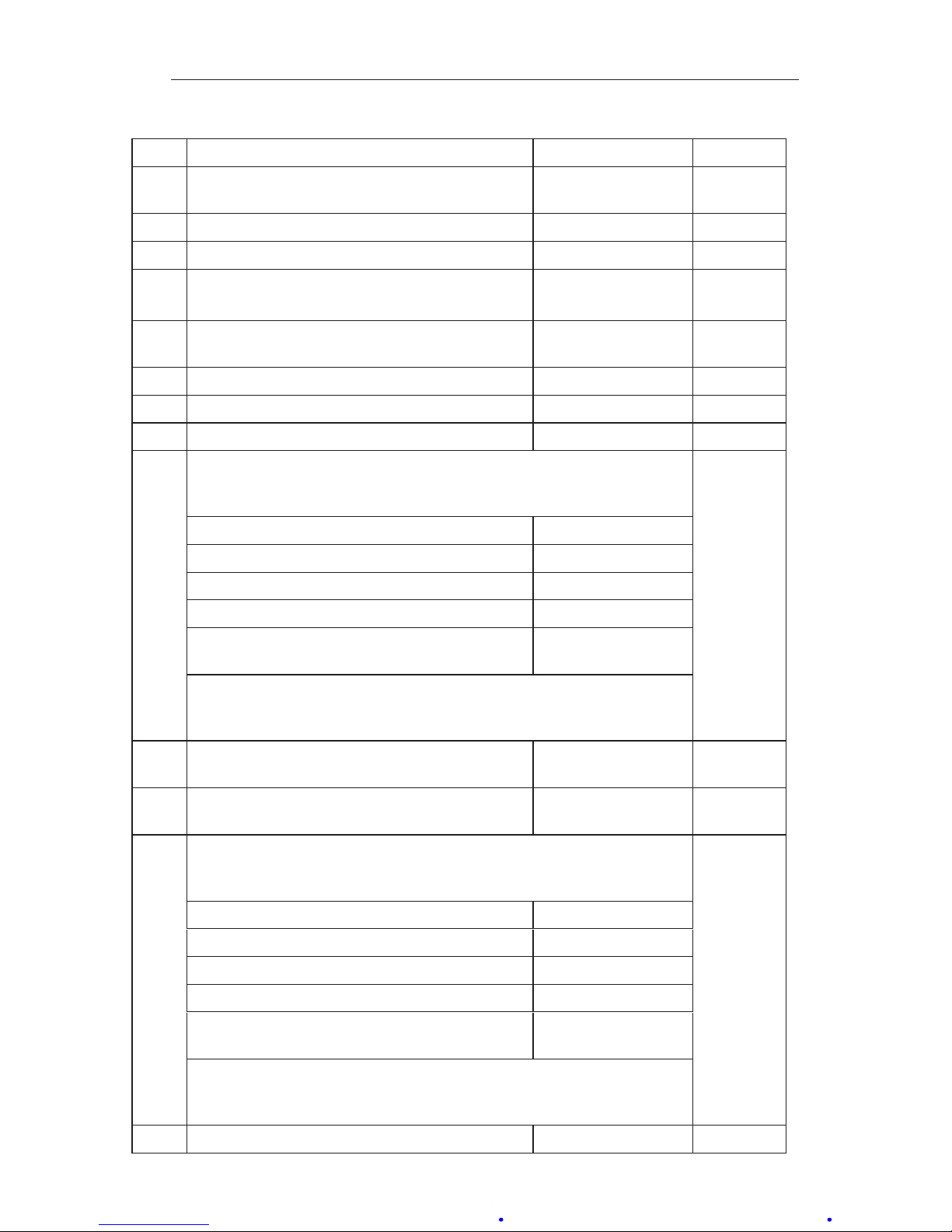
Item Description Part No. Per Unit
18 Screw, Flat, Skt Cap, 1/4-20 x 5/8, SST (Case
to DPU bracket)
9A-C0240-0009J 4
19 Gasket, Torque Tube 9A-C0199-0209C 1
20 Stud, Drive-Lok, Retaining, Bezel 9A-C0004-0005K 1
21 Screw, Relay Mtg. Hole Filler (if relay is not
installed, 2 per relay, not shown)
9A-C0111-0007J A/R
22 Ground Wire Assembly, External Wire See Table 4.2,
page 34
A/R
23
Ground Screw, Hex HD, 8-32 x 5/16, Grn
9A-C0117-1012J
1
24 Washer, Lock, Internal Tooth, #8, SST 9A-C0003-0066K 1
25 Washer, Lock, ET, #8, SST 9A-C0003-0050K 1
26 Switch and Plate Assembly:
(Tefzel Insulation-Radiation Resistant)
see also item 29
A/R
Low, SPDT 9A-CS666-1200B-N
Low, DPDT 9A-CS401-0184B-N
Low Relay 9A-CS666-0284B-N
Low #1, Independently Adjustable* 9A-CS666-0286B-N
Low #2, Independently Adjustable*
(not shown)
9A-CS666-0287B-N
*Note: If 3 or 4 independently adjustable switches are used, Low #1
is installed in the upper left position, and Low #2 is installed in the
lower right position.
27 External Wire Assembly, Low See Table 4.2,
page 34
A/R
28 External Wire Assembly, High See Table 4.2,
page 34
A/R
29 Switch and Plate Assembly:
(Tefzel Insulation-Radiation Resistant)
see also item 26
A/R
High, SPDT 9A-CS666-1201B-N
High DPDT 9A-CS401-0185B-N
High Relay 9A-CS666-0291B-N
High #1, Independently Adjustable* 9A-CS666-0288B-N
High #2, Independently Adjustable*
(not shown)
9A-CS666-0289B-N
*Note: If 3 or 4 independently adjustable switches are used, High #1
is installed in the upper right position, and High #2 is installed in the
lower left position.
30 Low Alarm, Drive Plate Assembly 9A-C0288-0026B A/R
Page 32
32
Section 4 Model 289A Differential Pressure Indicating Switch
Table4.1—PartsList,Model289AIndicatingSwitch
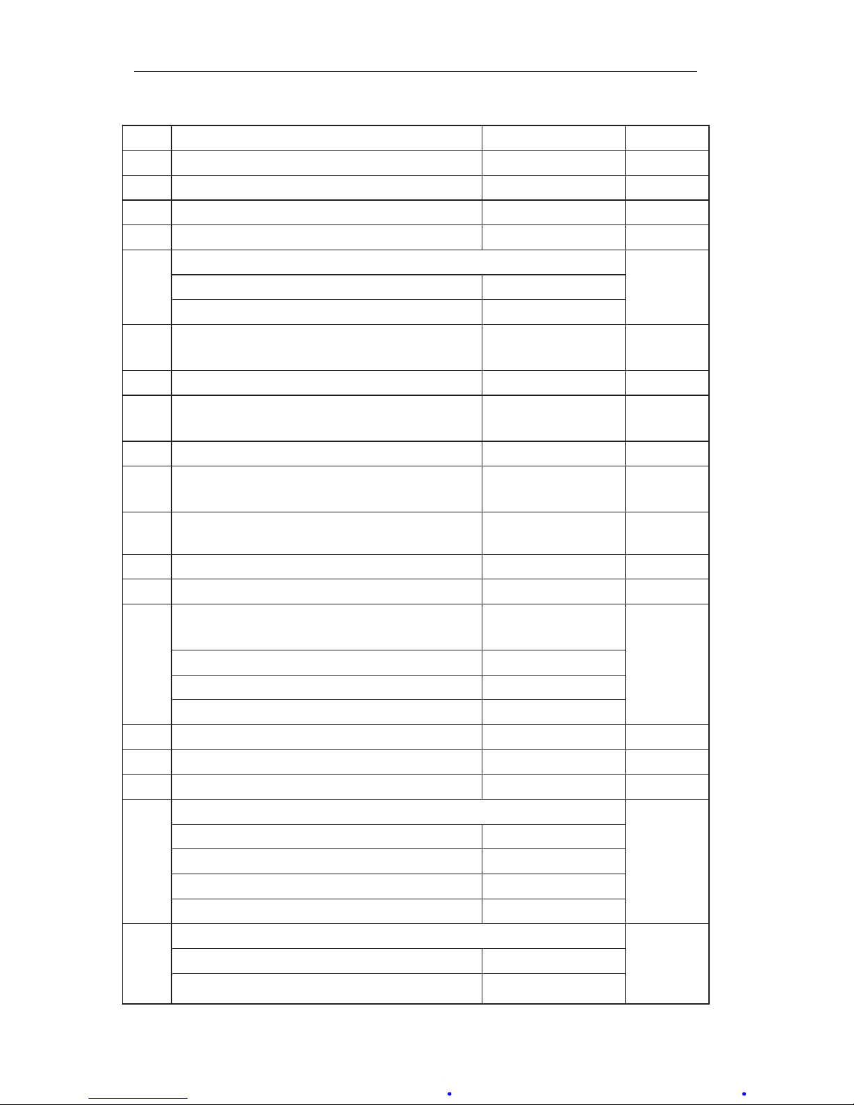
Item Description Part No. Per Unit
31 Low Switch, Switch Adjustment Index Assy 9A-C0288-0028B A/R
32 High Alarm, Drive Plate Assembly 9A-C0288-0027B A/R
33 High Switch, Switch Adjustment Index Assy 9A-C0288-0029B A/R
34 Washer, Spring (1 per switch) 9A-C0257-0019C A/R
35 Screw, Lock (1 per switch) A/R
Switch #1 and #2 9A-C0317-0012C
Switch #3 and #4 (not shown) 9A-CS469-0045Z
36
Washer, 1/2 OD x 0.14 ID, SST (1 per switch)
9A-C0317-0019C
A/R
37 Grip Ring (1 per switch) 9A-C0087-0011T A/R
38 Link Plate (2 required when both low and high
switches are used)
9A-C0288-0016C A/R
39 Strap 9A-C0288-0017C A/R
40 Screw, 3-48 x 3/16, SST, Binding Hd.
(3 per switch)
9A-C0117-0007J A/R
41 Screw, 8-32 x 1/4, SST, Binding Hd. (1 per
switch)
9A-C0117-0016J 1
42 Retaining Ring (1 per switch) 9A-C0087-0015T A/R
43 Washer, Flat, #3, SST (5 per switch) 9A-C0003-0045K A/R
44 Bezel Assembly (Bezel, Lens Cover, and
Gasket)
9A-C0277-0018B 1
Bezel (part of 9A-C0277-0018B) 9A-C0277-0029C
Lens Cover (part of 9A-C0277-0018B) 9A-C0181-0038C
Gasket (part of 9A-C0277-0018B)* 9A-C0277-0026C
45 Disc, Sealer, 1/2" (w/3M 468 Adhesive) 9A-C0192-1035T 1
46 Washer, Split Lock, #8, SST (1 per switch) 9A-C0003-0036K A/R
47 Sealing Compound, RTV 103 9A-C0006-1001V A/R
48** Scale Plate 1
White, 1 & 2 Switches 9A-C0288-1014C
Black, 1 & 2 Switches 9A-C0288-0031C
White, 3 & 4 Switches 9A-CS469-0025Z
Black, 3 & 4 Switches 9A-CS469-0068Z
49* Pointer Assembly 1
White 9A-C0288-0030B
Black 9A-C0288-0031B
Page 33
33
Model 289A Differential Pressure Indicating Switch Section 4
Table4.1—PartsList,Model289AIndicatingSwitch
Item Description Part No. Per Unit
50 Tape Seal Patches 9A-CIT10-1045G 10
Low Relay Assy (not shown)
(with Tefzel insulated wires)
Coil Voltage Wired SPDT Wired DPDT
115 VAC 9A-CS666-0238Z 9A-CS666-0245B
110 VDC 9A-CS666-0231Z 9A-CS666-0256B
1
High Relay Assy (not shown)
(with Tefzel insulated wires)
Coil Voltage Wired SPDT Wired DPDT
115 VAC 9A-CS666-0237Z 9A-CS666-0246B
110 VDC 9A-CS666-0230Z 9A-CS666-0279B
1
Spacer, Switch Plate (used w/ single high
switch or 3 independently adjustable switches
when #3 position is not used, not shown)
9A-C0258-0007C 1
Screw, Switch Lock Hole Filler (if switch is not
installed, 1 per switch, not shown)
9A-C0111-0028J A/R
Screw, Strap Hole Filler (if switch is not
installed, 1 per switch, not shown)
9A-C0119-0042J A/R
* Calibration Kit (not shown) 9A-0288-1032B A/R
* Recommended spare part
** If the scale plate is not identied with an SCR number, provide the following informtion:
Square root or linear graduations,
Scale (e.g., 0-100, 25-0-100, etc.)
Number of graduations (linear scales only)
Data (e.g., PSI, bar, inches of water column, meter, etc.)
Additional Notes:
1. A/R indicates as required.
2. When ordering parts, specify serial number of instrument.
3. For 199 DPU parts, refer to the Model 199 DPU user manual in Appendix A.
Page 34
34
Section 4 Model 289A Differential Pressure Indicating Switch
Table4.2—TefzelInsulation(RadiationResistant)ExternalWireLeads
(Table4.1,Items27and28)
WireType 2.5 ft 10ft 15 ft 20ft
Low #1 9A-CS666-0213Z 9A-CS666-0190Z 9A-CS666-0194Z 9A-CS666-0201Z
High #1 9A-CS666-0140Z 9A-CS666-0191Z 9A-CS666-0195Z 9A-CS666-0202Z
Low #2 9A-CS666-0166Z 9A-CS666-0241Z 9A-CS666-0268B 9A-CS666-0203Z
High #2 9A-CS666-0167Z 9A-CS666-0242Z 9A-CS666-0269B 9A-CS666-0204Z
Low Relay 9A-CS594-0137Z — — —
High Relay 9A-CS594-0138Z — — —
Ground 9A-CS666-0270B 9A-CS666-0271B 9A-CS666-0272B 9A-CS666-0273B
Page 35
35
Model 289A Differential Pressure Indicating SwitchSection 5
Section5—Installation/DimensionalDrawings
IMPORTANT: For DPU dimensional information, refer to the Model 199 DPU user
manual in Appendix A.
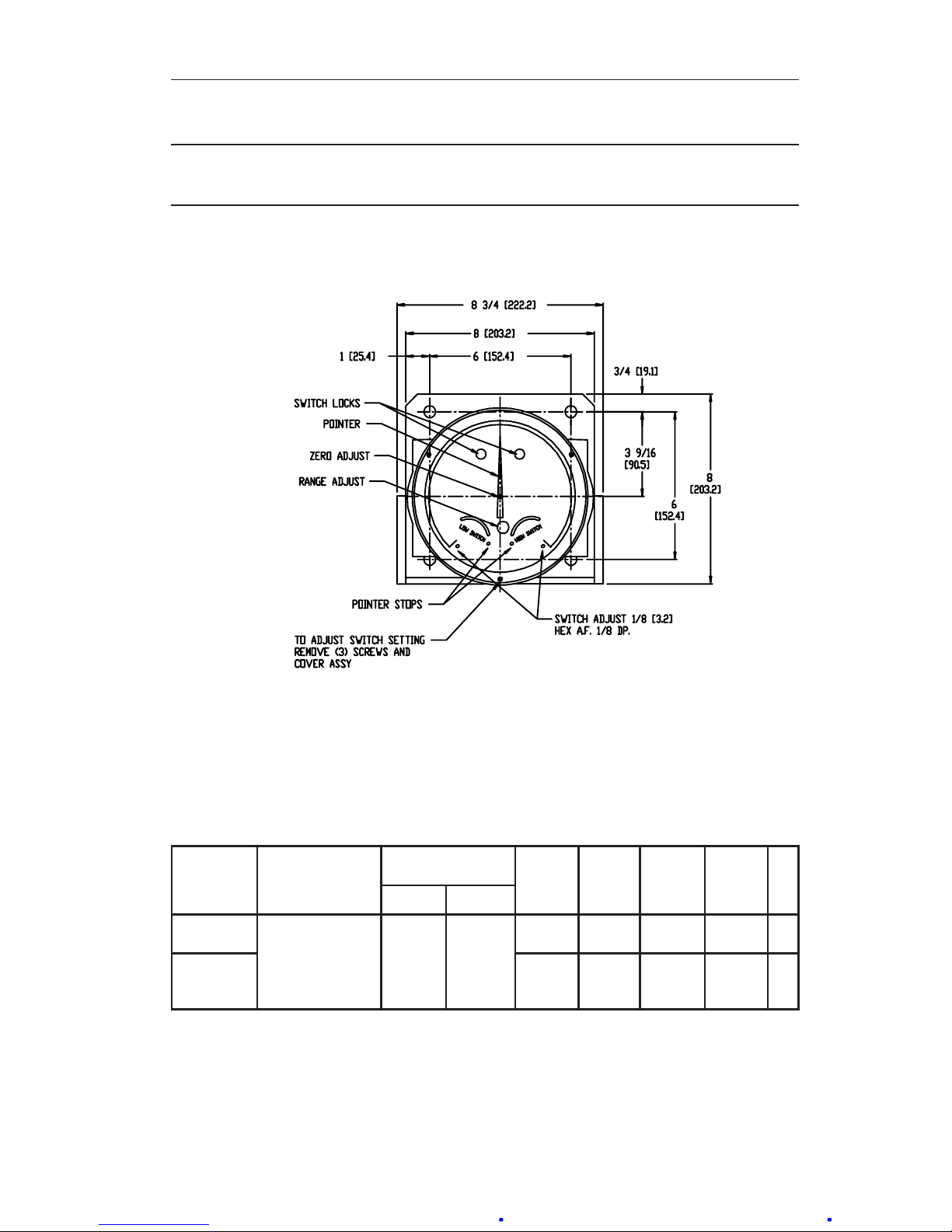
Figure 5.1—Model 289A, front view
Table 5.1—Model 289A Dimensions
(seeFigures5.2and5.3,page36)
PRESSURE
RATING
PSI
(MPa)
HOUSING
MATERIAL
PRESSURE
CONNECTION
DIM. A
INCHES
(mm)
DIM. B
INCHES
(mm)
DIM. C
INCHES
(mm)
DIM. D
INCHES
(mm)
# BOLTS
TOP BOTTOM
1,000
(6.9)
FORGED STNL
ST 316
1/2" NPT
1/4" NPT
1/4" NPT
1/2" NPT
1/4" NPT
1/2" NPT
1/4" NPT
1/2" NPT
9-29/32
(251.6)
6-5/8
(168.3)
2
(50.8)
2-9/64
(51.2)
12
3,000
(20.7)
10-5/32
(257.9)
7-1/8
(181.0)
2
(50.8)
2-9/64
(51.2)
12
NOTES:
Cast aluminum pipe mount supplied, unless otherwise specied. Specify pipe size when ordering threaded steel
adapter.
Metric conversions are approximate.
Page 36
36
Section 5 Model 289A Differential Pressure Indicating Switch
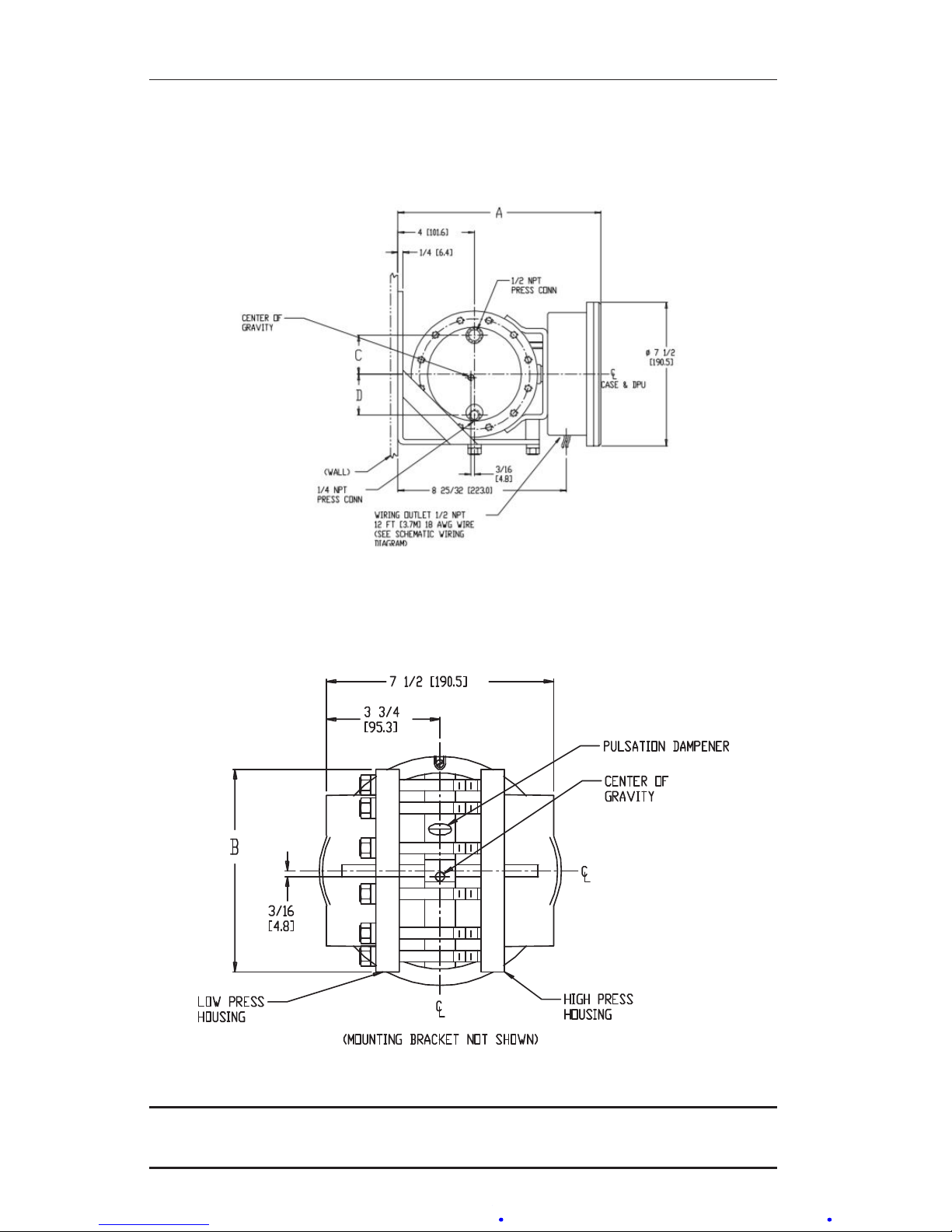
Figure 5.2—Model 289A, side view; see Table 5.1, page 35 for dimensions A, C and D
Figure 5.3—Model 289A, rear view; see Table 5.1, page 35 for dimension B
IMPORTANT: Model 289A version congurations are limited to nuclear applications;
also refer to the Model 199 DPU user manual in Appendix A.
Page 37

37
Product Warranty
A. Warranty
Cameron International Corporation ("Cameron") warrants that at the time of shipment, the prod-
ucts manufactured by Cameron and sold hereunder will be free from defects in material and
workmanship, and will conform to the specications furnished by or approved by Cameron.
B. Warranty Adjustment
(1) If any defect within this warranty appears, Buyer shall notify Cameron immediately.
(2) Cameron agrees to repair or furnish a replacement for, but not install, any product which
within one (1) year from the date of shipment by Cameron shall, upon test and examination by Cameron, prove defective within the above warranty.
(3) No product will be accepted for return or replacement without the written authorization of
Cameron. Upon such authorization, and in accordance with instructions by Cameron, the
product will be returned shipping charges prepaid by Buyer. Replacements made under
this warranty will be shipped prepaid.
C. Exclusions from Warranty
(1) THE FOREGOING WARRANTY IS IN LIEU OF AND EXCLUDES ALL OTHER
EXPRESSED OR IMPLIED WARRANTIES OF MERCHANTABILITY, OR FITNESS FOR
A PARTICULAR PURPOSE, OR OTHERWISE.
(2) Components manufactured by any supplier other than Cameron shall bear only the war-
ranty made by the manufacturer of that product, and Cameron assumes no responsibility
for the performance or reliability of the unit as a whole.
(3) "In no event shall Cameron be liable for indirect, incidental, or consequential damages
nor shall the liability of Cameron arising in connection with any products sold hereunder
(whether such liability arises from a claim based on contract, warranty, tort, or otherwise)
exceed the actual amount paid by Buyer to Cameron for the products delivered hereunder."
(4) The warranty does not extend to any product manufactured by Cameron which has
been subjected to misuse, neglect, accident, improper installation or to use in violation of
instructions furnished by Cameron.
(5) The warranty does not extend to or apply to any unit which has been repaired or
altered at any place other than at Cameron's factory or service locations by persons not
expressly approved by Cameron.
Product Brand
Barton® is a registered trademark of Cameron International Corporation ("Cameron").
Page 38
APPENDIX A
BARTON® NUCLEAR MODEL 199
DIFFERENTIAL PRESSURE UNIT (DPU)
User Manual
Part No. 9A-C10034, Rev. 03
November 2018
Contents
Technical Support ......................................................................................A-2
Section 1—Introduction ..............................................................................A-3
General ......................................................................................................A-3
Product Description....................................................................................A-3
Specications .............................................................................................A-4
Section 2—Theory of Operation .................................................................A-5
Basic Components .....................................................................................A-5
Pressure Housings.....................................................................................A-5
Bellows.......................................................................................................A-5
Range Springs ...........................................................................................A-7
Torque Tube Assembly...............................................................................A-7
Pulsation Dampener ..................................................................................A-8
Section 3—Installation/Operation ..............................................................A-9
Unpacking ..................................................................................................A-9
Mounting ....................................................................................................A-9
Flush or Panel Mounting ............................................................................A-9
Piping—Standard Practices .......................................................................A-9
All Applications (Flow and Liquid Level).....................................................A-9
Flow Applications .....................................................................................A-10
Liquid Level Applications..........................................................................A-10
Piping Diagrams.......................................................................................A-11
General Startup Practice Considerations.................................................A-17
Section 4—Maintenance, Adjustment, & Calibration .............................A-18
Tools Required for Maintenance and Calibration ..................................... A-18
DPU Inspection and Cleaning ..................................................................A-18
Pressure Check Procedure ......................................................................A-18
Inspection and Cleaning Procedure .........................................................A-19
Calibration Setup .....................................................................................A-20
Torque Tube Rotation Check (Replacement Units)..................................A-21
Range Change .........................................................................................A-21
2-1/8-inch Diameter Bellows ....................................................................A-21
Page 39
A-2
Safety
Before installing this product, become familiar with the installation instructions presented in Section 3 and all safety notes throughout.
WARNING:Thissymbolidentiesinformationaboutpracticesorcircumstances that can lead to personal injury or death, property damage, or
economic loss.
CAUTION: Indicates actions or procedures which if not performed correctly
may lead to personal injury or incorrect function of the instrument
or connected equipment.
IMPORTANT: Indicates actions or procedures which may affect instrument operation or
may lead to an instrument response that is not planned.
3-3/4-inch Diameter Bellows Without Kickoff Spring (>47" w.c.) .............. A-22
3-3/4-inch Diameter Bellows with Kickoff Spring ....................................A-23
Setting Bellows Travel..............................................................................A-25
Bellows Unit Assembly (BUA) Replacement
............................................A-25
Attaching Drive Arm to Torque Tube ........................................................A-26
Drive Arm Tightness Test
.........................................................................A-27
Adjusting Pulsation Dampener.................................................................A-27
Troubleshooting .......................................................................................A-27
Section 5—Parts Drawing/List .................................................................A-30
Section 6—Dimensional Drawings
..........................................................A-35
Technical Support
Cameron
Measurement Systems Division
14450 John F. Kennedy Blvd.
Houston, TX 77032
Phone: 1-800-654-3760; 281-582-9500
Fax: 281-582-9599
Barton is a registered trademark of Cameron.
© 2012 Cameron International Corporation (“Cameron”). All information contained in this
publication is condential and proprietary property of Cameron. Any reproduction or use
of these instructions, drawings, or photographs without the express written permission of
an ofcer of Cameron is forbidden.
All Rights Reserved.
Printed in the United States of America.
Page 40
A-3
Model 199 Differential Pressure Unit (DPU) Section 1
Section 1—Introduction
General
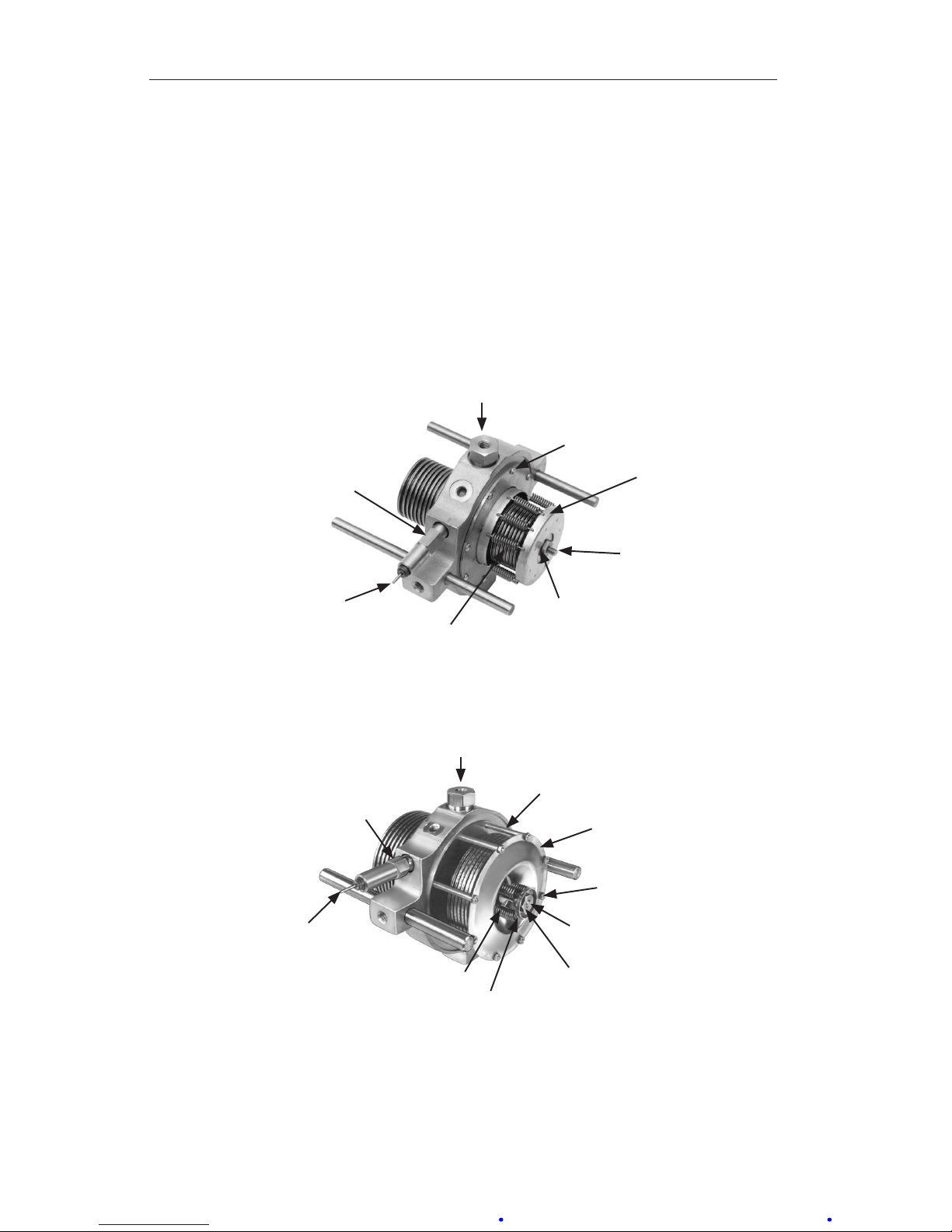
The Barton® Model 199 Differential Pressure Unit (DPU) (see Figure 1.1) is
a mechanical device which accurately measures differential pressure relative
to a gas or liquid owing through a process system, or to the level of a liquid
contained in a process vessel.
Figure 1.1—Model 199 DPU unit
For process ow measurements, the DPU is connected across a primary device (a venturi, an orice plate or a ow tube) located in the process system.
For liquid level measurements, the DPU may be connected in a variety of
ways to measure the difference in pressure caused by variations in the level of
the liquid in the process vessel.
Product Description
The Model 199 DPU is a dual bellows assembly enclosed within pressure
housings. The dual bellows assembly consists of two opposing internally con-
nected liquid-lled bellows, a center plate, range springs, overrange valves,
and a torque tube assembly.
The pressure housings are connected by pipe or tubing to the primary device
located in the system piping. Variations in differential pressure within the
pressure housings cause the bellows to expand or contract in a linear direction
towards the side having the lowest pressure.
The linear movement of the bellows is converted into angular rotation when
transmitted to the torque tube shaft by the drive arm and this mechanical
motion actuates the mechanism of the process monitoring instrument. The
process monitoring instrument that is connected to the torque tube assembly may be an indicator, a switch, a transmitter, a recorder, or other process
control device.
Page 41

A-4
Section 1 Model 199 Differential Pressure Unit (DPU)
Specications
Housing Material............................. Forged 316 Stainless Steel
Torque Tube Rotation (full scale DP) 8° ±10%
Torque Tube Material ...................... Beryllium Copper (BeCu)
Temperature Limits ......................... -40°F (-40°C) to +180°F (+82°C)
Maximum Non-linearity: .................. 0-10" w.c. to 0-400" w.c.
(0-25 mbar to 0-993 mbar)
±0.5% of full scale with appropriate linkage
........................................................ 0-401" w.c. to 0-100 psi
(0-996 mbar to 0-6.9 bar)
±0.75% of full scale with appropriate linkage
Repeatability ................................... 0.20% of full scale DP
Housing Materials/Ranges ............. Refer to Table 1.1
Table 1.1—Differential Pressure Ranges for Model 199 DPUs
SWP - psi
(bar)
Stainless Steel or Inconel Bellows
2 1/8”(55 mm) O.D. 3 3/4” (95 mm) O.D.
1,000
(69)
0-15 psi to 0-115 psi
(0-1 bar to 0-7.9 bar)
0-10" w.c. to 0-400" w.c.
(0-25 mbar to 0-995 mbar)
3,000
(207)
Net Volume, L.P. Head
(cu. in.)
35 cu. in. (575 cc) 30 cu. in. (490 cc)
Net Volume, H.P. Head
(cu. in.)
31 cu. in. (510 cc) 26 cu. in. (425 cc)
Displacement (cu. in.)
for full-scale travel
0.5 cu. in. (8.2 cc) 1.5 cu. in. (25 cc)
NOTES: Zero center or split ranges available on special order (e.g., 0-50" w.c. (0-124
mbar) range may be ordered 25-0-25" w.c. (62-0-62 mbar) or 10-0-40" w.c. (25-0-99 mbar).
Intermediate DP ranges available from 0-20" w.c. to 0-100 psi (0-50 mbar ot 0-6.9 bar).
Standard pressure connections are 1/2" (top) and 1/4" (bottom) NPT. Range springs are not
interchangeable between the different size bellows. Metric conversions are approximate.
Dimensional drawings available on request.
Page 42
A-5
Model 199 Differential Pressure Unit (DPU) Section 1
Section 2—Theory of Operation
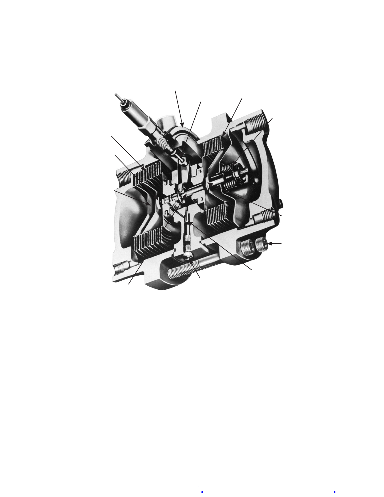
Basic Components
Low Pressure
Housing
HP Housing
Torque Tube
Shaft
Center Plate
Torque Tube
Low Pressure Bellows
Range Spring
High Pressure
Bellows
High Pressure
Overrange
Valve
Temperature
Compensator
Valve Stem
Low Pressure
Overrange
Valve
Housing
Bolts
Pulsation Damper
Damping Valve Plug
Figure 2.1—199 BUA cutaway
Pressure Housings
The two pressure housings of the Model 199 DPU are available in the various
safe working pressure ratings dened in Table 1.1, page A-4, and in the dimen-
sional drawings in Section 6.
Each pressure housing has two tapped connection ports: one port is located in
the top of the housing, the other port is located in the bottom of the housing.
Bellows
The bellows of the Model 199 DPU are available in the various materials
and sizes (refer to Table 1.1, page A-4) to accommodate the various calibration
ranges.
Page 43
A-6
Section 2 Model 199 Differential Pressure Unit (DPU)
The DPU has two bellows. One end of each bellows is sealed. The open end
of each bellows is attached and sealed to a side of the center plate (one bellows on each side) as shown in Figure 2.2.
The bellows and center plate are lled with ll liquid via the drive arm hole
plug. An opening through the center plate provides a passageway for the
transfer of ll liquid between the two bellows. This opening also allows the
bellows to be connected internally by a valve stem.
Drive Arm
Hole Plug
(DO NOT LOOSEN)
Retainer
Screws
Range
Spring
Assembly
Push
Rod
Lock Nut
Range
Springs
Torque
Tube
Shaft
Torque Tube Gland Nut
(DO NOT LOOSEN)
2-1/8" Bellows Unit Assembly (BUA)
Spring Post
Drive Arm
Hole Plug
(DO NOT LOOSEN)
Range Spring
Assembly
Retainer Nut
Spring
End Cup
Push Rod
Lock Nut
Range
Springs
Torque
Tube
Shaft
Torque Tube Gland Nut
(DO NOT LOOSEN)
3-3/4" Bellows Unit Assembly (BUA)
Figure 2.2—Bellows unit assemblies (BUAs)
Page 44
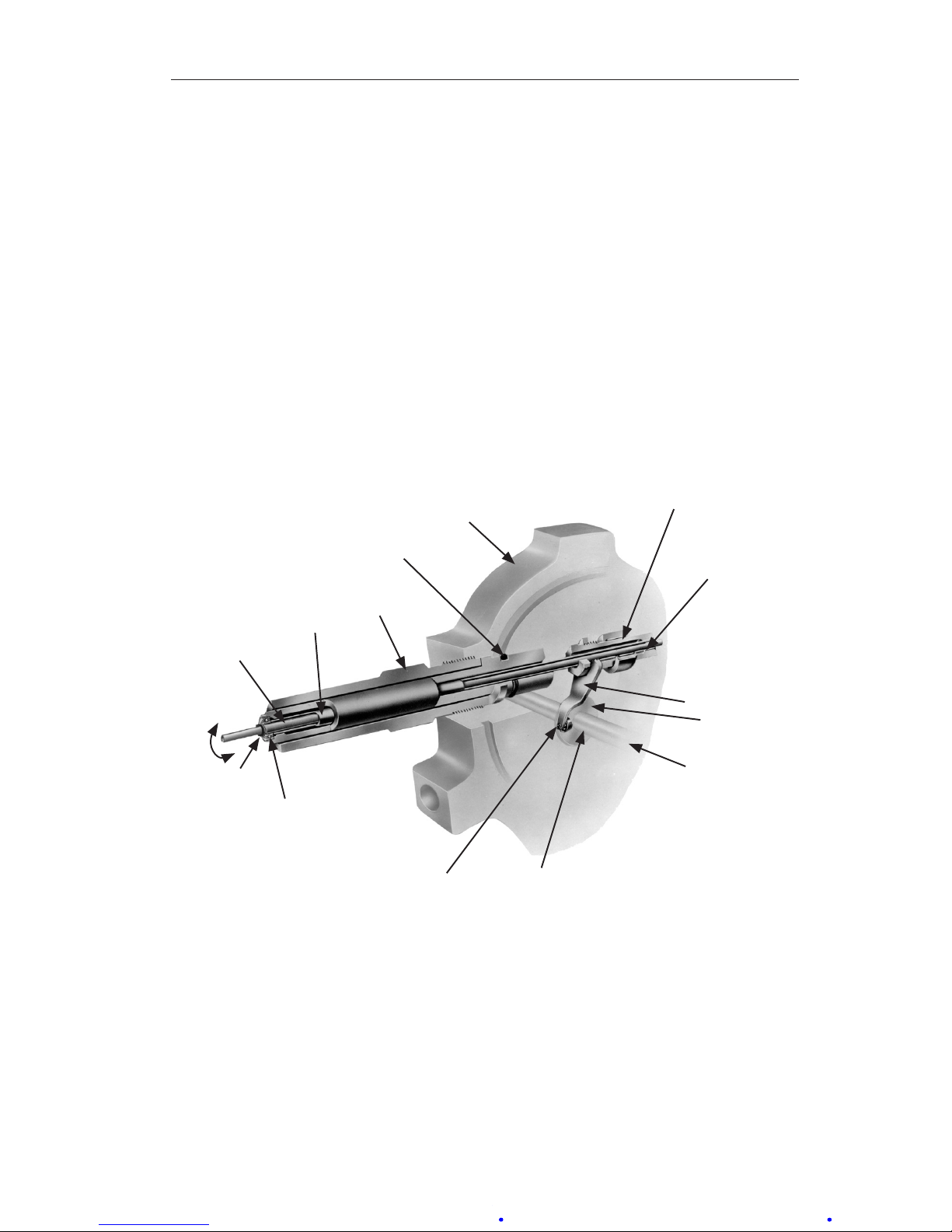
A-7
Model 199 Differential Pressure Unit (DPU) Section 2
Range Springs
The range of the dual-bellows type DPU is determined by the force required
to move the bellows through their normal range of travel.
The range springs, which are available in various ranges (see Table 1.1, page
A-4), act with the bellows and torque tube to balance the differential pressure ap-
plied to the unit. The number of springs used and their spring rate depends on
the individual differential pressure range requirement.
Torque Tube Assembly
As illustrated in Figure 2.3, the torque tube assembly consists of a torque
tube, a torque tube shaft, and the supporting members. The outboard end of
the torque tube shaft is attached to the center plate. The torque tube shaft,
located in the center of the torque tube, is welded to the inboard end of the
tube.
Needle Beaing
Center Plate
Weld
Drive Arm
Valve Stem
Disc
0.200"
Bellows Travel
Valve Stem
Minature
Precision
Ball Bearing
Jewel Bearing
Torque Tube
Shaft
Torque Tube
Torque Tube
Lock Nut
O-Ring Seal
Weld
8°
Rotation
Figure 2.3—Torque tube assembly
Movement of the bellows is transmitted by the drive arm to the torque tube as
a rotary motion. Since the torque tube is attached to the center plate, the tube
must twist when subjected to torque. The torque tube shaft, which is freely
supported within the torque tube at its outer end, but connected to the torque
tube and drive arm at its inner end, rotates through the same angle as the differential pressure unit.
Page 45

A-8
Section 2 Model 199 Differential Pressure Unit (DPU)
Pulsation Dampener
The pulsation dampener (Figure 2.1, page A-5) controls the ow of ll-liquid
between the high and low-pressure bellows with an externally adjustable pul-
sation dampener needle valve. Restriction of liquid ow reduces the effects of
pulsation. In applications where pulsation is not a problem, the needle valve is
set to the full-open position.
Page 46

A-9
Model 199 Differential Pressure Unit (DPU) Section 3
Section 3—Installation/Operation
Unpacking
The 199 DPU should be inspected at time of unpacking to detect any damage
that may have occurred during shipment.
IMPORTANT: The instrument was checked for accuracy at the factory. Do not change
any of the settings during examination or accuracy will be affected.
IMPORTANT: For application in critical media, requiring special cleaning processes
and precautions, a polyethylene bag is used to protect the instrument
from contamination. This protective bag should be removed only under
conditions of controlled extreme cleanliness.
IMPORTANT: Do not locate the instrument near vents or bleed holes that discharge
corrosive vapors or gases.
Mounting
Flush or Panel Mounting
Attach the case of the instrument (switch or indicator) to the panel or wall.
Refer to the instrument's installation manual for mounting details.
Piping—Standard Practices
All Applications (Flow and Liquid Level)
1. Shorten the distance between the primary device and the DPU as much
as possible. Distances exceeding 100 feet are not recommended. For distances up to 50 feet, use 1/4-inch or 3/8-inch pipe or tubing. For runs of
50 to 100 feet, use 1/2-inch pipe or tubing. The recommended limitation
does not apply if an air purge or blow-back system is used.
2. Slope all piping at least one inch per linear foot to avoid liquid or gas
entrapment.
3. Provide 2 feet of non-insulated piping between the DPU and the primary
device for each 100°F (+37.8°C) in excess of +200°F (+93.3°C).
4. Assure that the temperature of the DPU never exceeds 180°F (+82°C).
When steam tracing is necessary, the steam pressure should not exceed
5 pounds per square inch and insulation should not be used. If pressure
must exceed 5 pounds per square inch, limit the length of tubing around
the DPU to two turns and do not insulate.
Page 47
A-10
Section 3 Model 199 Differential Pressure Unit (DPU)
5. Install a suitable pulsation dampening device upstream of the DPU.
Where severe pulsation is present, the accuracy of the ow measurement
will be affected.
6. Mount the DPU on a solid support to minimize vibration. Tighten all
points, using a suitable compound; leaks in piping can cause measurement errors.
7. Install a valve manifold connecting the DPU and the source of differential pressure to facilitate operation and checking of the DPU.
8. Locate all shutoff valves and bypass valves to be readily accessible from
the front of the instrument. Locate block valves at the source of differential pressure.
Flow Applications
Assure that the DPU high-pressure housing is connected to the upstream tap
of the primary device.
IMPORTANT: To prevent overheating the DPU during blowdown, monitor the tempera-
ture by placing hands on the pipe between the DPU and the manifold
pipe containing the vent valves.
Liquid Level Applications
The process media may be used as a reference leg seal uid if it will condense
in the reference leg under all conditions.
If the process or process media characteristics are such that the above condi-
tions cannot be met, a special reference leg seal uid is required. The special
seal uid must not be volatile and must not be miscible with the process
media. Also, the difference in the densities of the special seal uid and the
process media will require compensation in calculating the differential pressure range of the DPU.
WARNING: Explosion Hazard—Organic compounds, oil, grease, dirt, or
scale of any kind cannot be tolerated in an oxygen installation.
Page 48
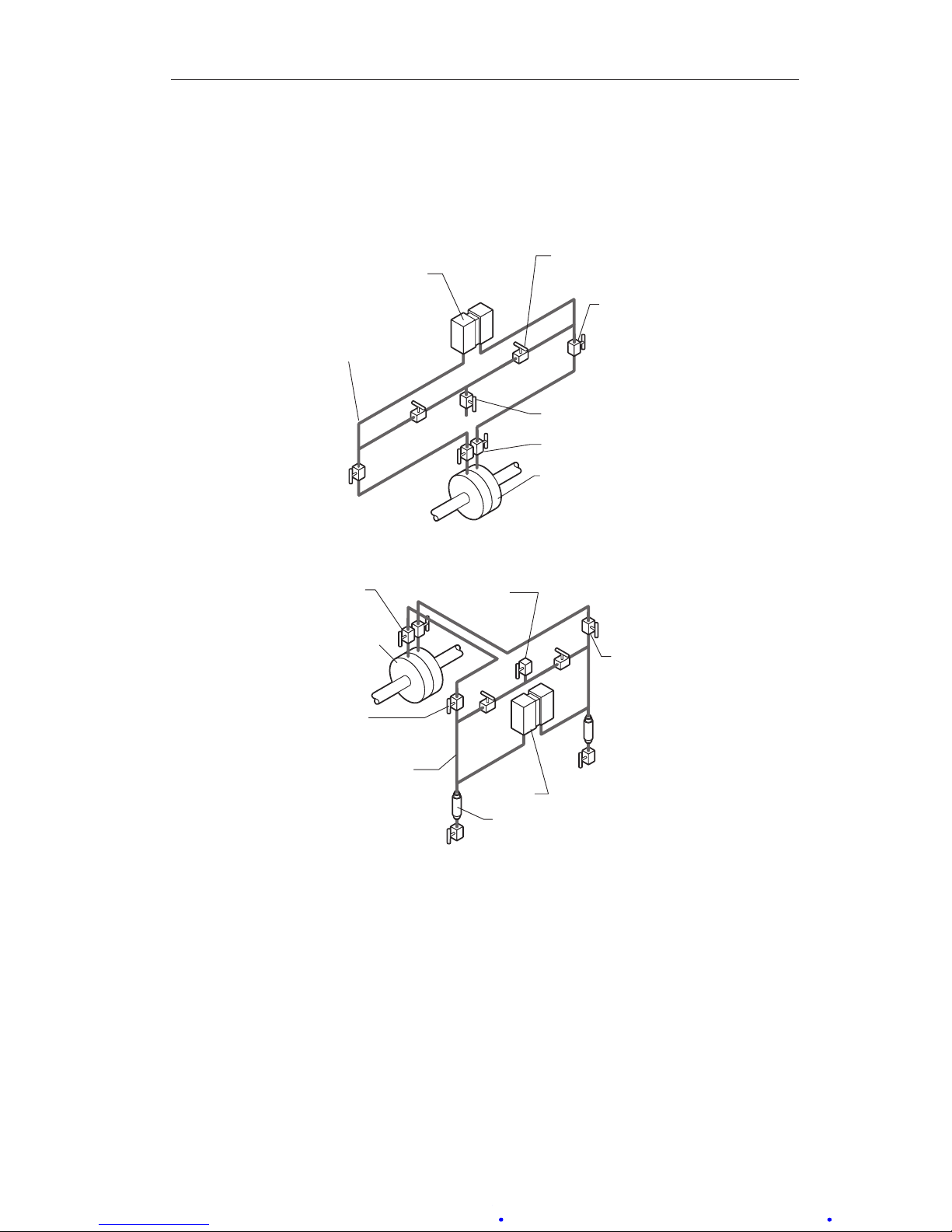
A-11
Model 199 Differential Pressure Unit (DPU) Section 3
Piping Diagrams
Diagrams for typical and special ow applications are presented on the following pages. Use the diagram best suited for the application as a guide for
piping conguration.
BLOCK VALVES
PRIMARY DEVICE
STATIC PRESSURE
CONNECTION
(USE ONLY ONE)
BYPASS
VALVES
VENT VALVE
SHUT-OFF
VALVES
DPU
Figure 3.1—Gas Flow, DPU Above Run
BLOCK
VALVES
PRIMARY
DEVICE
STATIC PRESSURE
CONNECTION
(USE ONLY ONE)
BYPASS
VALVES
VENT
VALVE
SHUT-OFF
VALVES
DPU
DRIP POTS
Figure 3.2—Gas Flow, DPU Below Run
Page 49
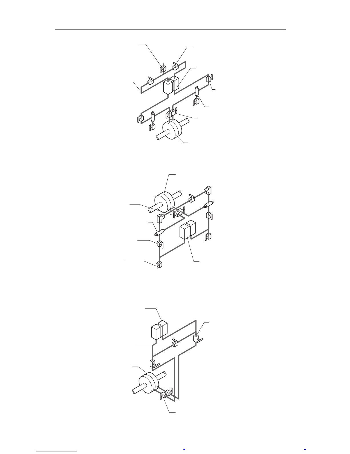
A-12
Section 3 Model 199 Differential Pressure Unit (DPU)
BLOCK
VALVES
PRIMARY DEVICE
DRIP POTS
STATIC PRESSURE
CONNECTION
(USE ONLY ONE)
BYPASS
VALVES
VENT
VALVE
SHUT-OFF
VALVES
DPU
Figure 3.3—Gas Flow, Hydrates Present
DPU
PLUGS
BLOCK
VALVES
CONDENSING
RESERVOIR
PRIMARY
DEVICE
SHUT-OFF
VALVES
VENT
VALVES
(OPTIONAL)
Figure 3.4—Steam Flow, DPU Below Run
BLOCK VALVES
PRIMARY
DEVICE
BYPASS
VALVE
SHUT-OFF
VALVES
DPU
Figure 3.5— Liquid Flow, DPU Above Run
Page 50
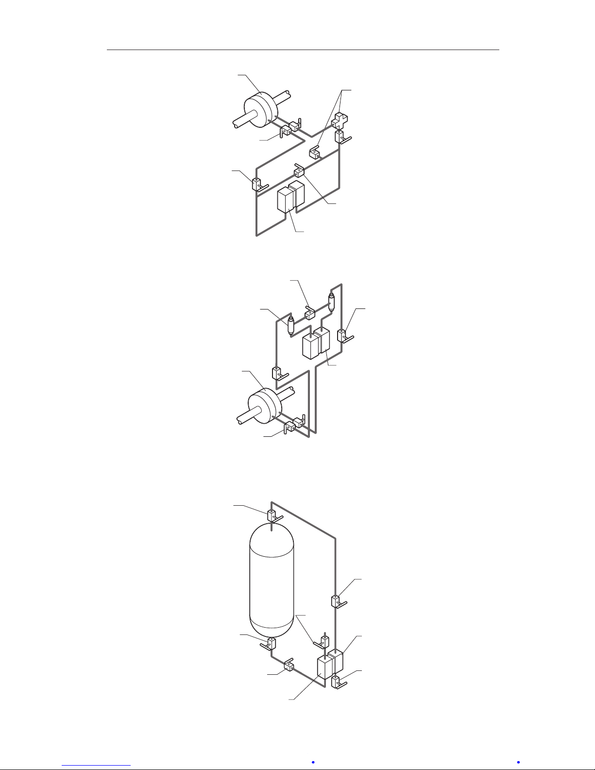
A-13
Model 199 Differential Pressure Unit (DPU) Section 3
BLOCK
VALVES
PRIMARY
DEVICE
BYPASS
VALVE
FILL TEE AND
VENT VALVE
FOR HOT OR
GASSY LIQUIDS
SHUT-OFF
VALVES
DPU
Figure 3.6—Liquid Flow, DPU Below Run
BLOCK
VALVES
SEAL
POTS
PRIMARY
DEVICE
BYPASS
VALVE
SHUT-OFF
VALVES
DPU
Figure 3.7—Corrosive Liquid Flow
DRAIN
VALVE
BLOCK
VALVE
HIGH-PRESSURE
DPU
BLOCK
VALVE
SHUT-OFF
VALVE
VENT
VALVE
SHUT-OFF
VALVE
Figure 3.8—Cool Non-Condensing Liquid, DPU Level with Tank Bottom
Page 51
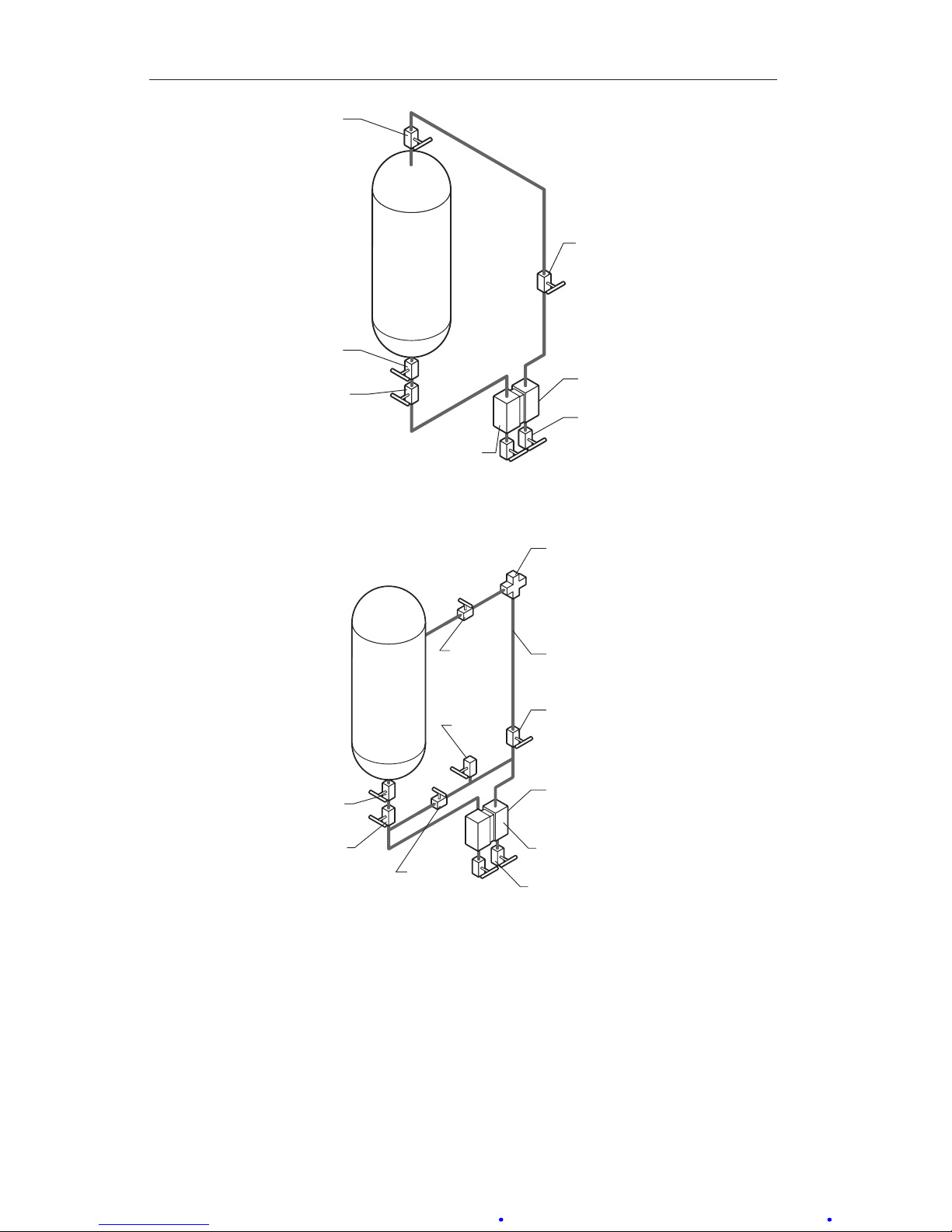
A-14
Section 3 Model 199 Differential Pressure Unit (DPU)
HIGH-PRESSURE
SHUT-OFF
VALVE
BLOCK
VALVE
DRAIN
VALVE
DPU
SHUT-OFF
VALVE
BLOCK
VALVE
Figure 3.9—Cool Non-Condensing Liquid, DPU Below Tank
HIGH-PRESSURE
SHUT-OFF
VALVE
REFERENCE
LEG
2" CROSS
BYPASS
VALVE
VENT
VALVE
BLOCK
VALVE
BLOCK
VALVE
DPU
SHUT-OFF
VALVE
DRAIN VALVE
Figure 3.10—DPU Below Tank Bottom with Reference Leg
Page 52
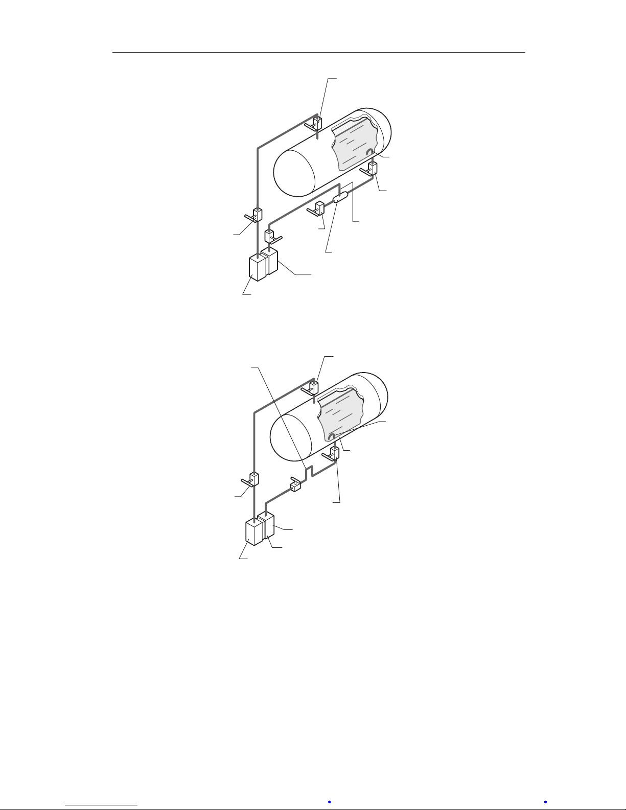
A-15
Model 199 Differential Pressure Unit (DPU) Section 3
SHUT-OFF
VALVE
LOW-PRESSURE
DRAIN
VALVE
BLOCK
VALVE
INVERTED "U"
GAS TRAP
MINIMUM LENGTH
6 INCHES
DPU
BLOCK VALVE
VAPOR GENERATOR
Figure 3.11—Liquid CO2
LOW-PRESSURE
HIGH-PRESSURE
SHUT-OFF
VALVE
INVERTED "U"
GAS TRAP
VAPOR GENERATOR
FLAT TUBULAR SPIRAL
IN OUTER 1/3 OF TANK
INSULATION KEEP
DEAD LEG BETWEEN
TANK AND SPIRAL
5 INCHES OR LESS
MINIMUM LENGTH
12 INCHES
BLOCK VALVE
BLOCK
VALVE
DPU
Figure 3.12—Cryogenic Liquids
Page 53

A-16
Section 3 Model 199 Differential Pressure Unit (DPU)
SHUT-OFF VALVES
BLOCK VALVES
HIGH PRESSURE
GAS
SUPPLY
SIGHT FLOW
GAGE
BYPASS VALVE
DPU
INPUT GAS
REGULATOR
Figure 3.13—Bubbler System
SHUT-OFF VALVES
BLOCK VALVES
HIGH-PRESSURE
GAS
SUPPLY
INPUT GAS
REGULATOR
SIGHT FLOW GAGES
WITH THROTTLING VALVES
BYPASS VALVE
DPU
Figure 3.14—Liquid Specic Gravity
Page 54

A-17
Model 199 Differential Pressure Unit (DPU) Section 3
General Startup Practice Considerations
Observe the following practices when starting up an instrument.
1. Always start with the block valves closed.
2. Perform a zero check on the instrument as follows.
IMPORTANT: For gas service, it is recommended that zero check be performed with
both block valves closed. If the gas ow is pulsating, there may be a
standing wave effect in the process line which can displace the indicator
and appear as a zero error.
a. Open the bypass valve(s), then open one shutoff valve. This proce-
dure equalizes the pressure between both sides of the instrument.
The instrument should indicate zero.
b. If the instrument does not indicate zero, check for gas or liquid en-
trapment in the lines or in the DPU (depending on the orientation of
the piping layout and service).
c. If necessary, adjust the pen or pointer by turning the zero adjust on
the instrument.
3. Check the manifold and piping for leaks as follows.
a. Open the bypass valve(s), then open one shutoff valve to pressurize
the instrument.
b. Close the shutoff valve and the bypass valve.
c. Any leakage will be indicated by pen or pointer movement, up or
down scale.
IMPORTANT: Be careful not to subject the DPU to unnecessary shock or overrange
pressure during operations.
Page 55
A-18
Section 4 Model 199 Differential Pressure Unit (DPU)
Section 4—Maintenance, Adjustment, & Calibration
Tools Required for Maintenance and Calibration
Cameron's calibration tool kit (Part No. 9A-0202-1005B) contains the tools
necessary for calibrating the Model 199 DPU. The tools listed in Table 4.1 are
also recommended for performing general maintenance.
Table 4.1—Tools
Description Purpose
7/16" Hex wrench Housing bolts
5/8" Hex wrench Housing bolts
1/8" Allen wrench Dampener Adjustment
1/2" Open ended wrench Push rod - bellows cup connection
Modied box/open-ended wrench (7/16") Kickoff spring lock nut
100 ft-lb Torque wrench Housing bolts
DPU Inspection and Cleaning
Instruments used in services where solids or semi-solids may accumulate
inside the pressure housings require periodic inspection and cleaning. Always
check for internal pressure using the procedure below before removing the
DPU housing bolts.
Pressure Check procedure
WARNING: Failure to perform this procedure can result in severe injury,
death or substantial property damage due to the release of internal
pressure. If the DPU has been installed in gas applications with working
pressures greater than 200 psig, PERFORM THIS PROCEDURE BEFORE
REMOVING THE DPU HOUSING BOLTS.
1. Back off all housing bolts 4 turns.
2. Check for internal pressure by attempting to move the housing in and out
along the bolts.
a. If the housing moves freely, no pressure is present and servicing or
repair may continue.
b. If the housing does not move freely, the bellows may be pressurized
and is potentially hazardous if further disassembled. Tighten the
bolts and return the unit to the factory or authorized Barton service
center for repair. Tag the unit and specify "Gas in Bellows".
Page 56
A-19
Model 199 Differential Pressure Unit (DPU) Section 4
Inspection and Cleaning Procedure
Instruments used in services where solids or semi-solids may accumulate
inside the pressure housings require periodic inspection and cleaning, as follows.
1. Remove the DPU from service and remove the pressure housings.
2. Carefully remove the pressure housings from the bellows unit assembly.
IMPORTANT: If accumulation of solids or semi-solids is extensive, rapid removal of the
pressure housings can damage the bellows.
3. Remove the accumulation from between the bellows convolutions and
from the inside of the housings. Use a solvent if possible. Do not use a
sharp instrument to clean between convolutions.
4. Look for broken range springs and replace as necessary.
5. Replace the housings and seals.
6. Install NEW pressure housing bolts and torque in accordance with Table
4.2.
WARNING: Do not reuse housing bolts. Reuse of housing bolts, especiallyincriticalapplicationslikehydrogensuldeandsaltwaterexposures, can result in severe injury, death or substantial property damage
due to bolt failure.
Table 4.2—Standard Bolt Torque Ratings
SWP
Housing
Mat'l
Bolt
Mat'l
Size Qty Part No.
Lube
(Note 1)
Torque (lb/ft)
(Note 2)
Rotation
(Note 3)
1000
Stainless
Steel
Steel 3/8-16 x 4.5 12 9A-C0199-1345C Ye s 40 270°
3000
Stainless
Steel
Steel
1/2-13 x 5.5 12 9A-C0199-0085C Yes 80 180°
NOTES:
1. Lubricants: Molykote G paste, Teon-base pipe dope, graphite-base grease, or similar lubricants. Lube rst 2 threads only. Do not lube bearing surface.
2. Torque on bolts is accomplished in 3 or 4 steps. Tighten UNIFORMLY.
3. Rotation of bolt head is measured after bolt is "snug," with approximately 5 lb/ft torque. DO NOT
EXCEED THIS ROTATION. To tighten bolts without torque wrench, use rotation values.
Page 57
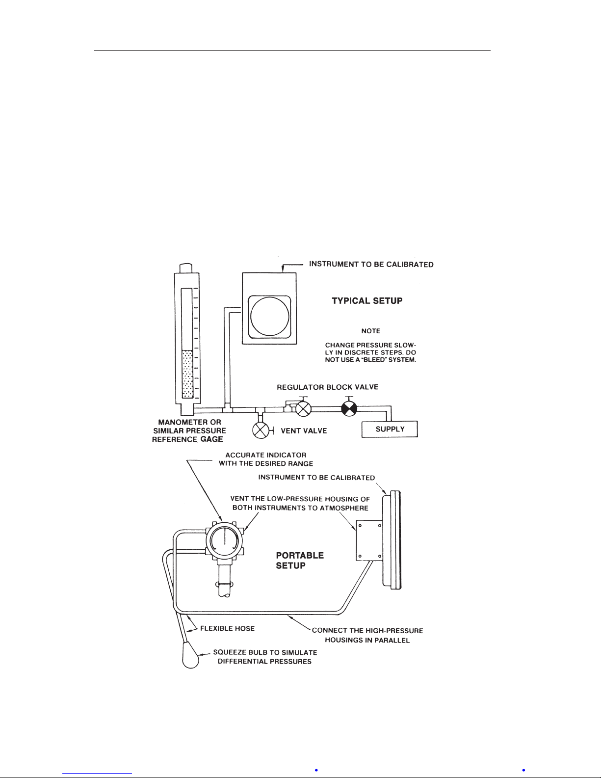
A-20
Section 4 Model 199 Differential Pressure Unit (DPU)
Calibration Setup
The test equipment required to calibrate the Model 199 DPU, when attached
to an indicator or switch is shown in Figure 4.1.
All Barton instruments using the Model 199 DPU as actuator are calibrated at
the factory.
All DPUs sold as replacement units or as actuators for other applications are
checked for accuracy prior to shipment.
Normally, the DPU is calibrated after installation on a specic instrument.
Refer to the separate instrument manual for specic calibration procedures.
Figure 4.1—Calibration setup
Page 58

A-21
Model 199 Differential Pressure Unit (DPU) Section 4
Torque Tube Rotation Check (Replacement Units)
Prior to installation as a replacement unit, a DPU should be checked for
proper torque tube rotation, per the following procedure:
1. Mount DPU on a stable base and connect to a standard pressure source.
2. Adapt a scale graduated in degrees to the torque tube housing.
3. Adapt a pointer to the exposed end of the torque tube shaft.
4. Apply 100% DP to the high pressure (HP) housing of the DPU. The
pointer should indicate 8 degrees of travel.
Range Change
Changing the range of the Model 199 DPU may require replacing the bellows
unit assembly with a unit of the desired range (see Bellows Unit Assembly
(BUA) Replacement, page A-25).
WARNING: High-pressure gas hazard on disassembly of the DPU in
installations with pressures greater than 200 psig. To prevent possible
severe personal injury, death, or substantial property damage due to the
release of internal pressure, PERFORM THE PRESSURE CHECK BEFORE
REMOVING DPU HOUSING BOLTS.
IMPORTANT: If accumulation of solids or semi-solids is extensive, remove the hous-
ings carefully to prevent damaging the bellows.
IMPORTANT: The calibration range of the DPU was carefully set at the factory. The
following procedure maintains the original factory bellows travel setting
while the range spring change is performed. This procedure must be
strictly followed while changing the range spring assembly or altering the
adjustment.
To replace the range spring assembly with either a new assembly of the same
range or one with a different range value, proceed as follows (this procedure
assumes that the DPU is either connected to an indicating instrument or tted
with a scale and pointer to measure torque tube shaft movement):
2-1/8-inch Diameter Bellows
1. Remove the DPU from service.
2. Remove the pressure housing bolts and the low-pressure housing.
3. With the pointer at zero, remove the spring retainer screw, retainer
springs, and the range spring assembly.
IMPORTANT: The pointer will shift from zero. This is a normal action and the pointer
should not be readjusted at this point.
Page 59
A-22
Section 4 Model 199 Differential Pressure Unit (DPU)
4. Install the new range spring assembly onto the push rod, and replace the
spring retainer screw.
5. If the pointer is set above zero, rotate the spring adjustment clockwise
until the pointer is set at zero. If the pointer is below zero, rotate the
spring adjustment counterclockwise until the pointer is set at zero.
6. Replace and tighten the lock nut. If the pointer shifts from zero, loosen
the lock nut and reset the pointer as in step 5. Tighten the lock nut.
7. Replace the low-pressure housing and install NEW bolts (new gaskets
are also recommended). Torque the bolts in accordance with Table 4.2,
page A-19.
WARNING: Do not reuse housing bolts. Reuse of housing bolts, especiallyincriticalapplicationslikehydrogensuldeandsaltwaterexposures, can result in severe injury, death or substantial property damage
due to bolt failure.
8. Calibrate in accordance with the manual for the actuated instrument.
3-3/4-inch Diameter Bellows Without Kickoff Spring (>47" w.c.)
1. Remove the instrument from service.
2. Remove the pressure housing bolts and the low-pressure housing.
3. With the pointer set at zero, remove the lock nut retainer nuts, and the
range spring assembly. To remove the range spring assembly, rotate the
assembly counterclockwise while pulling outward on the assembly.
IMPORTANT: The pointer will shift from zero. This is a normal action and the pointer
should not be readjusted at this point.
4. Thread the new assembly onto the push rod, and align the holes in the
range spring assembly with the spring posts. Replace and tighten the
retainer nuts.
5. Using a spanner wrench, rotate the spring adjustment until the pointer
is set at exact zero. Replace and tighten the lock nut. The pointer must
remain at the zero setting. If the pointer shifts from zero, loosen the lock
nut and repeat this step.
6. Replace the low-pressure housing and install NEW bolts (new gaskets
are also recommended). Torque the bolts in accordance with Table 4.2,
page A-19.
WARNING: Do not reuse housing bolts. Reuse of housing bolts, especiallyincriticalapplicationslikehydrogensuldeandsaltwaterexposures, can result in severe injury, death or substantial property damage
due to bolt failure.
7. Calibrate in accordance with the manual for the actuated instrument.
Page 60
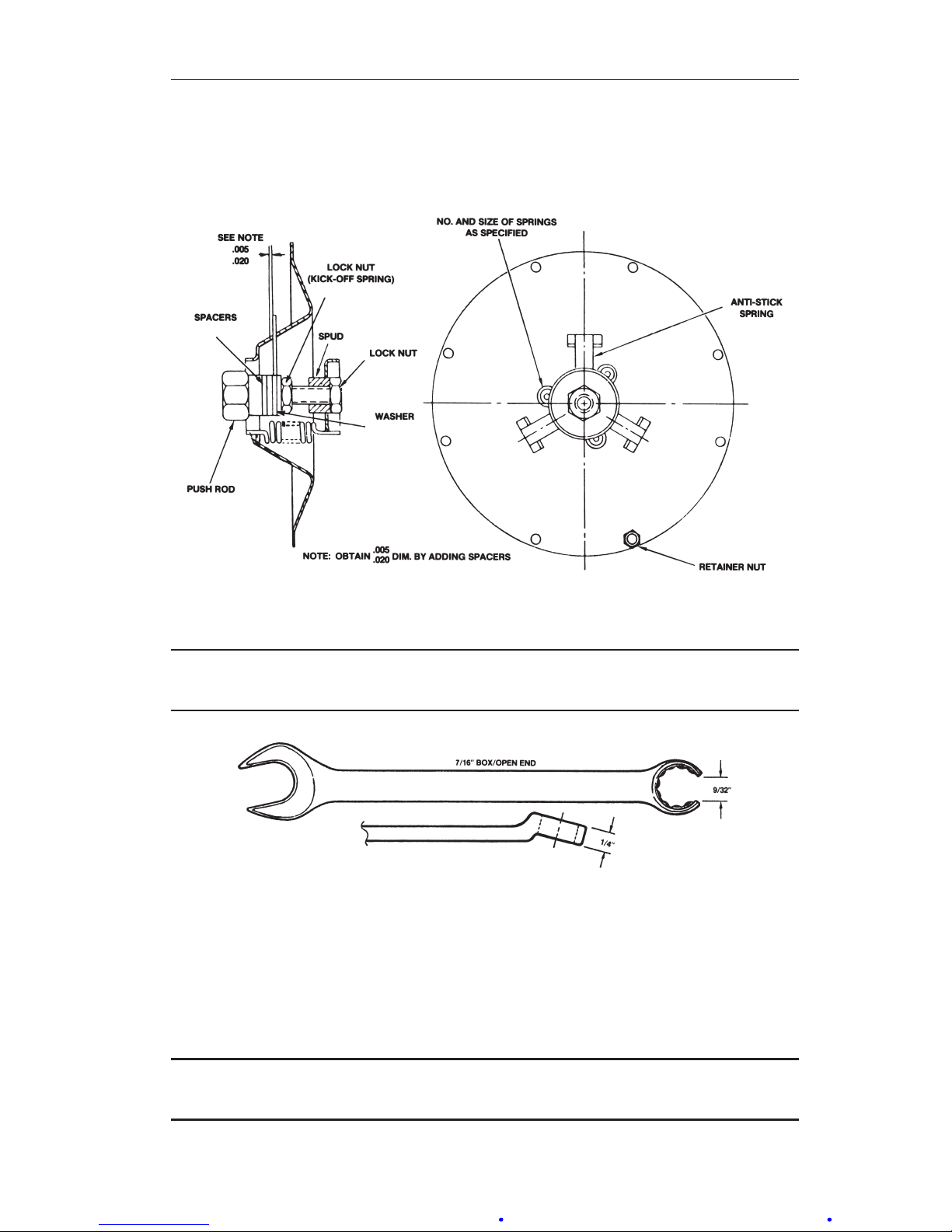
A-23
Model 199 Differential Pressure Unit (DPU) Section 4
3-3/4-inch Diameter Bellows with Kickoff Spring
The kickoff spring (also referred to as the "anti-stick" spring) is supplied as
standard equipment with 46" w.c. and lower range DPUs.
Figure 4.2—Kickoff spring assembly
IMPORTANT: The lock nut requires a modied 7/16", 12-point box wrench for tighten-
ing (Figure 4.3).
Figure 4.3—Wrench modication
1. Remove the instrument from service. Set the pointer at zero using the
instrument zero adjustment.
2. Remove the pressure housing bolts and remove the low-pressure housing.
3. With the pointer set at zero, remove the lock nut, spring retainer nuts,
washer and lock nut, and range spring assembly.
IMPORTANT: The pointer will shift from zero. This is a normal action and the pointer
should not be readjusted at this time.
Page 61
A-24
Section 4 Model 199 Differential Pressure Unit (DPU)
4. Install the range spring assembly, using a 1/2-inch open-ended wrench to
connect the push rod to the low-pressure bellows cup.
IMPORTANT: The range spring assembly consists of the range springs, kickoff spring
assembly, and the push rod. The assembly is furnished as a complete
and assembled unit.
5. Position range spring assembly over retainer posts and replace retainer
nuts.
6. Insert the tubing between the range springs and tighten inboard lock nut.
7. Zero the pointer by adjusting the spud on the push rod. Be sure that the
kickoff spring is not engaged during this operation.
8. Position the kickoff spring to prevent interference with the coil springs
and tighten the kickoff spring lock nut. If clearance is needed for the
wrench, note the position of the spud (measure with a scale or count
threads to the end of the push rod) and move the spud for the required
clearance. After the lock nut is tightened, return the spud to its original
position.
9. Check the back-clearance between the kickoff spring and the slot. Use a
wire feeler gage or comparable measuring device. The clearance between
slots will vary, but must be at least 0.005-in. to prevent interference with
instrument zero. Add or remove washers as required to obtain the proper
clearance. Tighten the lock nut securely.
10. Install the jam nut and lock the spud to the push rod. Hold with pliers.
If the spud was moved in step 8, return the spud to the proper position
before tightening the jam nut.
11. Apply 100 percent negative pressure to the high-pressure side of the DPU
and repeat the clearance check and adjustment described in step 9.
12. Apply 100 percent positive pressure to the high-pressure side of the DPU
and repeat the clearance check and adjustment described in step 9.
13. Release all pressure from the instrument, replace the low-pressure housing and install NEW bolts (new gaskets are also recommended). Torque
the bolts in accordance with Table 4.2, page A-19.
WARNING: Do not reuse housing bolts. Reuse of housing bolts, especiallyincriticalapplicationslikehydrogensuldeandsaltwaterexposures, can result in severe injury, death or substantial property damage
due to bolt failure.
Page 62
A-25
Model 199 Differential Pressure Unit (DPU) Section 4
Setting Bellows Travel
The travel of the DPU bellows must be adjusted if one of the following occurs.
1. The range spring assembly is removed without following the procedure.
2. Broken range springs are replaced.
3. The indicator pointer has excessive overtravel.
4. The indicator pointer has excessive undertravel.
Setting the bellows travel requires that the DPU be attached to the actuated
instrument and connected to a test pressure source. The procedure for this
adjustment is presented in the manual for the actuated instrument.
Bellows Unit Assembly (BUA) Replacement
Before replacing the BUA, read the following warning messages and reference Figure 2.1, page A-5, to locate parts described in the following procedure.
WARNING: High-pressure gas hazard on disassembly of the DPU in
installations with pressures greater than 200 psig. To prevent possible
severe personal injury, death, or substantial property damage due to the
release of internal pressure, perform the pressure check procedure on
page A-18 before removing the DPU housing bolts.
IMPORTANT: If accumulation of solids or semi-solids is extensive, remove the hous-
ings carefully to prevent damaging the bellows.
IMPORTANT: Component Removal—See the manual for the actuated instrument for
particular components that must be removed to gain access to DPU case
mounting screws. Support DPU during disassembly. Do not loosen the
drive arm hold plug (located in the top of the BUA center plate) when
removing the mounting bracket. If the plug is loosened, bellows ll uid
will be lost.
1. Disconnect the DPU piping and remove the instrument from service.
2. Loosen the actuated instrument drive arm and slide off of the torque tube
shaft. Do not disconnect the instrument linkage.
3. Remove the case-retaining screws and remove the case assembly.
4. Remove the indicator bracket screws and the indicator bracket.
5. Remove the pressure housings bolts and pressure housings.
6. Place the pressure housings on the replacement bellows unit assembly
and insert and start (only) the pressure housing bolts.
Page 63

A-26
Section 4 Model 199 Differential Pressure Unit (DPU)
WARNING: Do not reuse housing bolts. Reuse of housing bolts, especial-
lyincriticalapplicationslikehydrogensuldeandsaltwaterexposures,
can result in severe injury, death or substantial property damage due to
bolt failure.
7. Attach the indicator bracket to the replacement assembly, using the indicator bracket screws.
8. Attach the mounting bracket using the screws provided.
9. Support the DPU and tighten and torque the pressure housing bolts in
accordance with Table 4.2, page A-19.
10. Attach the case assembly using case retaining screws.
11. Attach the drive arm and linkage.
12. Tighten the drive arm to the torque tube, as described below.
13. Replace any instrument components that were removed (refer to the "Important: Component Removal" notice on page A-19).
14. Calibrate the instrument before returning it to service.
Attaching Drive Arm to Torque Tube
1/8” WRENCH
(PN 9A-0163-0044C)
CLAMP SCREW
DRIVE ARM
LINK
SINTERED
CLAMP BLOCK
TO TIGHTEN
.03 (approx)
SHAFT
Figure 4.4—Drive arm to torque tube connection
1. Slip the drive arm over the torque tube shaft; clear the end of the torque
tube housing by approximately 0.030 inches before securing to prevent
interference.
2. To tighten the drive arm assembly onto the torque tube shaft:
a. Supporting the block and shaft, tighten the clamp screw until it is
snug to the shaft.
b. Still supporting the block/shaft, tighten the clamp screw an addition-
al 1/3 to 1/2 turn. (The screw can normally turn one full revolution
before breaking.)
Page 64

A-27
Model 199 Differential Pressure Unit (DPU) Section 4
Drive Arm Tightness Test
This procedure tests the tightness of the drive arm's connection to the torque
tube by applying torque developed by the DPU onto a xed drive arm. Care
should be taken to apply pressure slowly, as torque is being applied to the
connection through the torque tube drive shaft.
1. With the pointer at normal 0% torque tube rotation position (0% on a
normal 0 to 100% scale unit), adjust the drive arm stop bracket (or use
alternate means) to prevent the pointer from moving (stop bracket interferes with drive arm movement).
IMPORTANT: On reverse acting/split range units, it will be necessary to pressurize
the DPU to move the pointer to the minimum scale position, and on
suppressed units, it will be necessary to apply pressure to establish a
reference point to check for "zero" shift.
2. Pressurize the DPU to full calibrated scale DP (100% of full scale range)
to apply 8 degrees of torque tube equivalent torque to the connection.
3. Observe the shift in the unit "zero" following DPU depressurization (as
required) and drive arm stop bracket readjusting (to allow free movement
of drive arm and pointer). If the "zero" shifts counter-clockwise more
than 1/2%, tighten the clamp block to prevent drive arm slippage.
Adjusting Pulsation Dampener
Reference Figure 6.1, page A-35, for the location of the pulsation dampener valve.
1. Remove the dust cover and insert a 1/8-in. hex key into the needle valve.
2. Turn the valve clockwise to the closed position, approximately 3 turns.
3. Back out the valve 1/2 turn or as required to reduce pulsations/shock
pressures.
Troubleshooting
See Table 4.3, page A-28, and refer to actuated instrument manual for more infor-
mation.
Page 65

A-28
Section 4 Model 199 Differential Pressure Unit (DPU)
Table 4.3—Troubleshooting Chart
Trouble
Possible Source
Probable Cause
Corrective Action
Low or No
Indication
Primary Element
or Differential
Pressure Source
Orice installed backwards
or oversized
Replace orice
Flow blocked upstream
from run
Clean out run or
open valve
Loss of liquid in reference
leg (liquid level)
Rell reference leg
Density changes in process media or reference
leg
Rell reference leg
with same density
liquid as process
media
Piping from
Primary Element
to DPU
Pressure tap holes
plugged
Clean out piping
Bypass valve open or
leaking
Close bypass
valve(s) or repair
leaks
Liquids or gases trapped
in piping
Vent piping
Block or shutoff valves
closed
Open block or shutoff valves
Piping leaks, HP side Repair leaks
Bellows Unit Housing(s) lled up with
solids, restricting bellows
movement
Clean out housing(s)
Gas trapped (liquid service) or liquid trapped (gas
service) in housing(s)
Vent housing(s)
HP Housing gasket leaks Replace gasket
DPU tampered with Return BUA for
repair
Mechanism Loose links/movements Tighten or replace
Out of calibration Calibrate
Corrosion or dirt in mechanism
Clean or replace
Pointer loose Tighten pointer
Page 66

A-29
Model 199 Differential Pressure Unit (DPU) Section 4
Table 4.3—Troubleshooting Chart
Trouble
Possible Source
Probable Cause
Corrective Action
High
Indication
Primary Orice partially restricted
or too small
Clean out or replace
Piping from
Primary Element
to DPU
Leak in LP side piping Repair leaks
Bellows Unit Gas trapped (liquid
service) in LP housing or
liquid trapped (gas service) in HP housing
Vent housing
LP housing gasket leaks Replace gasket
Range spring broken or
DPU tampered with
Return BUA for
repair
Mechanism Loose links or movements Repair or replace
Out of calibration Calibrate
Erratic
Indication
Primary Flow pulsating Install dampening
device upstream of
DPU run
Piping from
Primary Element
to DPU
Liquid trapped in gas
piping or gas bubble in
liquid piping
Remove (see
Startup Procedure,
Section 3)
Vapor generator incorrectly installed
Repipe
Reference leg gassy or
liquid vaporizing
See piping instructions
Bellows Unit Obstructed bellows travel Clean bellows
Gas trapped in DPU HP or
LP housing
Remove (see
Startup Procedure,
Section 3)
Mechanism Linkage dragging or dirty Adjust or clean
Pointer dragging on scale
plate
Adjust
Page 67
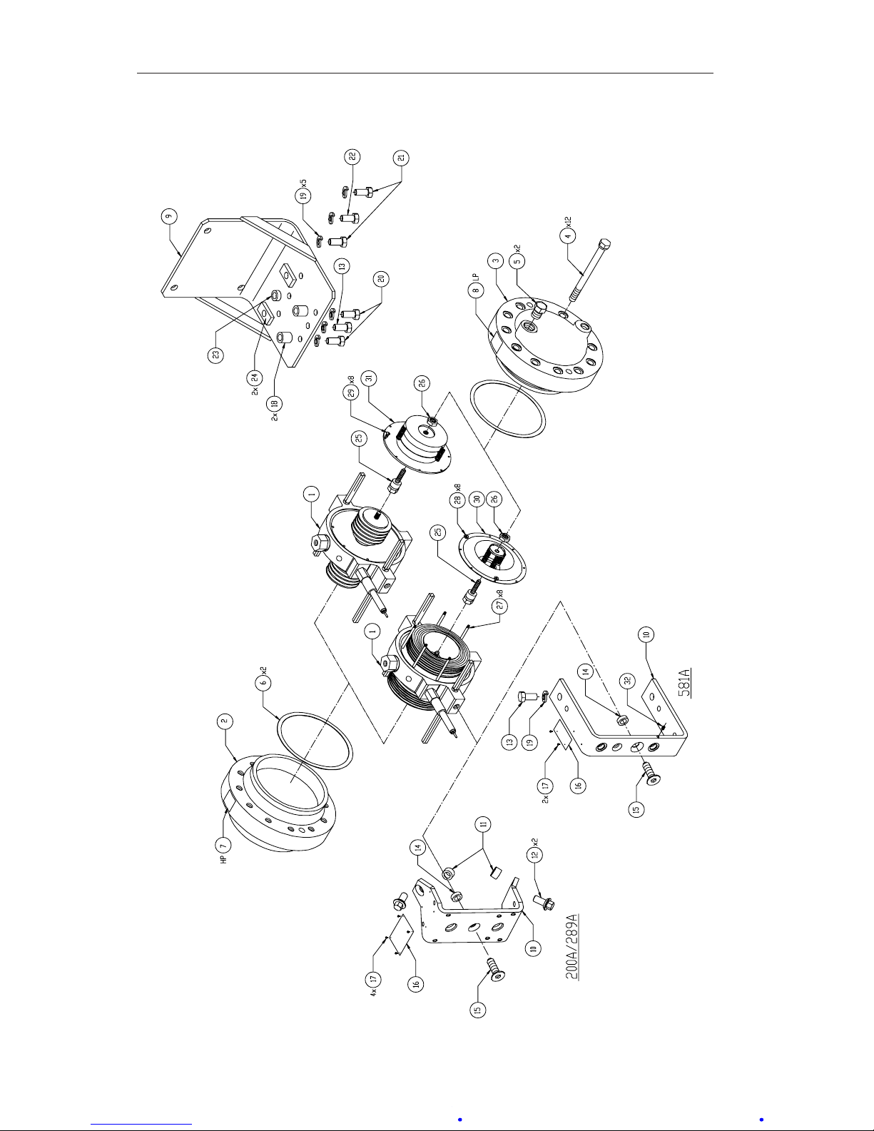
A-30
Section 5 Model 199 Differential Pressure Unit
Section 5—Parts Drawing/List
Figure 5.1—Model 199 DPU parts drawing (indicator and indicator switch mounting
brackets vary as shown; see 200A/289A and 581A insets)
Page 68
A-31
Model 199 Differential Pressure Unit Section 5
Table 5.1—Model 199 Parts List
Item Description Part No.
Per
Unit
1 BUA (BELLOWS UNIT ASSEMBLY) SELECT 1
2 HOUSING, PRESSURE, TAPPED (MATCH PORTS WITH
ITEM 3)
1
HOUSING, 1 K SST, 1/4 X 1/4 NPT 9A-CS787-0071C
HOUSING, 1 K SST, 1/4 X 1/2 NPT (TOP/BOTTOM) 9A-CS787-0061C
HOUSING, 1 K SST, 1/2 X 1/4 NPT (TOP/BOTTOM) 9A-C0199-1038C
HOUSING, 1 K SST, 1/2 X 1/2 NPT 9A-CS787-0025Z
HOUSING, 3 K SST, 1/4 X 1/4 NPT 9A-CS787-0066C
HOUSING, 3 K SST, 1/4 X 1/2 NPT (TOP/BOTTOM) 9A-CS787-0057Z
HOUSING, 3 K SST, 1/2 X 1/4 NPT (TOP/BOTTOM) 9A-C0199-1042C
HOUSING, 3 K SST, 1/2 X 1/2 NPT 9A-CS787-0058C
3 HOUSING, PRESSURE, DRILLED (MATCH PORTS
WITH ITEM 2)
1
HOUSING, 1 K SST, 1/4 X 1/4 NPT 9A-CS787-0072C
HOUSING, 1 K SST, 1/4 X 1/2 NPT (TOP/BOTTOM) 9A-CS787-0060C
HOUSING, 1 K SST, 1/2 X 1/4 NPT (TOP/BOTTOM) 9A-C0199-1037C
HOUSING, 1 K SST, 1/2 X 1/2 NPT 9A-CS787-0026Z
HOUSING, 3 K SST, 1/4 X 1/4 NPT 9A-CS787-0067C
HOUSING, 3 K SST, 1/4 X 1/2 NPT (TOP/BOTTOM) 9A-CS787-0056Z
HOUSING, 3 K SST, 1/2 X 1/4 NPT (TOP/BOTTOM) 9A-C0199-1041C
HOUSING, 3 K SST, 1/2 X 1/2 NPT 9A-CS787-0059C
4 BOLT, HOUSING, 1 K 9A-C0199-1345C 12
BOLT, HOUSING, 3 K 9A-C0220-1116J
5 PLUG, PIPE, 1/4"NPT, 316 SST 9A-C0199-0214C 2
PLUG, PIPE, 1/2"NPT, 316 SST 9A-C0199-0215C
6 GASKET, PRESSURE HOUSING, NICKEL 9A-C0199-0184C 2
7 LABEL, HIGH PRESSURE 9A-0199-0194C 1
8 LABEL, LOW PRESSURE 9A-0199-0195C 1
9 BRACKET, MOUNTING, 1 K MODEL 200A/289A 9A-C0199-1493B 1
BRACKET, MOUNTING, 3 K MODEL 200A/289A 9A-CS787-0047Z
BRACKET, MOUNTING, 3 K MODEL 581A 9A-C0199-1109B
10 BRACKET, INDICATOR - MODEL 200A/289A 9A-CS748-0006Z 1
BRACKET, INDICATOR - MODEL 581A 9A-C0197-1019C
11 SPACER, INDICATOR BRACKET - MODEL 200A/289A 9A-C0199-0006C 2
12 SCREW, HEX WASHER HEAD, 3/8-16 X 1-1/8 9A-C0002-1009T 2
13 SCREW, HEX HD, 3/8-16 X 3/4 - MODEL 581A 9A-C0116-0007J 2
14 BRACKET SPACER 9A-C0199-0003C 1
Page 69
A-32
Section 5 Model 199 Differential Pressure Unit
Table 5.1—Model 199 Parts List
Item Description Part No.
Per
Unit
15 SCREW, FL HEX SOC CAP HD 3/8-16 X 7/8, ST -
MODEL 200A/289A
9A-C0240-0003J 1
SCREW, FL HEX SOC CAP HD 3/8-16 X 1 -
MODEL 581A
9A-C0240-0004J
16 TAG, S/N, DPU MTG BRK - MODEL 200A/289A 9A-C0199-0002G 1
TAG, S/N, DPU MTG BRK - MODEL 581A 9A-C0224-0003G
17 DRIVE SCREW, RD HD, #0 X 3/16, SS -
MODEL 200A/289A
9A-C0600-1003J 4
DRIVE SCREW, RD HD, #0 X 3/16, SS - MODEL 581A 2
18 SPACER, MOUNTING BRACKET - MODEL 200A/289A 9A-CS787-0008Z 2
19 WASHER, SPLIT LOCK, 3/8, SST 9A-C0003-0093K 5
20 SCREW, CAP HEX HD 3/8-16 X 1-1/2 ST ZP -
MODEL 200A/289A
9A-C0210-0011J 2
21 SCREW, CAP HEX HD 3/8-16 X 1 ST ZP, 1 K -
MODEL 200A/289A
9A-C0210-1007J 2
SCREW, CAP HEX HD 3/8-16 X 3/4 ST ZP, 3 K -
MODEL 200A/289A
9A-C0210-0012J
SCREW, CAP HEX HD 3/8-16 X 3/4 ST ZP, 3 K -
MODEL 581A
9A-C0116-0007J
22 SCREW, CAP HEX HD 3/8-16 X 1 ST ZP -
MODEL 200A/289A
9A-C0210-1007J 1
SCREW, HEX HD, 3/8-16 X 1 - MODEL 581A 9A-C0116-0006J
23 SPACER, CENTER PLATE - MODEL 200A/289A 9A-CS787-0009Z 1
24 SPACER - BLACK EPOXY, 1 K - MODEL 200A/289A 9A-CS787-0006Z 2
25 SPRING PUSH ROD 9A-C0199-0049C 1
26 LOCK NUT, SPRING ADJUST 9A-C0199-0144C 1
27 SPRING RETAINER POST, ROUND, 10-19"WC 9A-C0199-0257C 8
SPRING RETAINER POST, HEX, 20-400"WC 9A-C0199-1337C
28 NUT, SPRING POST, 8-32, ROUND 9A-C0199-0258C 8
NUT, SPRING POST, 6-32, HEX 9A-C0500-0028J
29 SCREW, CALIBRATION SPRING RETAINER, RD HD,
6-32 X 5/16, SST
9A-C0111-0049J 8
30 CALIBRATION SPRING ASSEMBLY, 3-3/4 BELLOWS 1
SPRING ASSY, INC, 0 - 10" WC 9A-C0199-1385B
SPRING ASSY, INC, 0 - 12" WC 9A-C0199-1387B
SPRING ASSY, INC, 0 - 14" WC 9A-C0199-1388B
SPRING ASSY, INC, 0 - 16" WC 9A-C0199-1392B
SPRING ASSY, INC, 0 - 18" WC 9A-C0199-1393B
SPRING ASSY, INC, 0 - 20" WC 9A-C0199-1389B
SPRING ASSY, INC, 20 - 22" WC 9A-C0199-1386B
Page 70
A-33
Model 199 Differential Pressure Unit Section 5
Table 5.1—Model 199 Parts List
Item Description Part No.
Per
Unit
30
(cont.)
SPRING ASSY, INC, 23 - 27" WC 9A-C0199-1391B 1
SPRING ASSY, INC, 28 - 31" WC 9A-C0199-1395B
SPRING ASSY, INC, 32 - 38" WC 9A-C0199-1397B
SPRING ASSY, INC, 39 - 46" WC 9A-C0199-1390B
SPRING ASSY, INC, 47 - 55" WC 9A-C0199-1410B
SPRING ASSY, INC, 56 - 64" WC 9A-C0199-1396B
SPRING ASSY, INC, 65 - 72" WC 9A-C0199-1399B
SPRING ASSY, INC, 73 - 79" WC 9A-C0199-1402B
SPRING ASSY, INC, 80 - 88" WC 9A-C0199-1412B
SPRING ASSY, INC, 89 - 96" WC 9A-C0199-1394B
SPRING ASSY, INC, 97 - 107" WC 9A-C0199-1420B
SPRING ASSY, INC, 108 - 120" WC 9A-C0199-1409B
SPRING ASSY, INC, 121 - 130" WC 9A-C0199-1405B
SPRING ASSY, INC, 131 - 142" WC 9A-C0199-1411B
SPRING ASSY, INC, 143 - 155" WC 9A-C0199-1415B
SPRING ASSY, INC, 156 - 167" WC 9A-C0199-1398B
SPRING ASSY, INC, 168 - 183" WC 9A-C0199-1403B
SPRING ASSY, INC, 184 - 195" WC 9A-C0199-1407B
SPRING ASSY, INC, 196 - 212" WC 9A-C0199-1426B
SPRING ASSY, INC, 213 - 232" WC 9A-C0199-1401B
SPRING ASSY, INC, 233 - 245" WC 9A-C0199-1406B
SPRING ASSY, INC, 246 - 258" WC 9A-C0199-1417B
SPRING ASSY, INC, 259 - 276" WC 9A-C0199-1418B
SPRING ASSY, INC, 277 - 291" WC 9A-C0199-1419B
SPRING ASSY, INC, 292 - 316" WC 9A-C0199-1425B
SPRING ASSY, INC, 317 - 349" WC 9A-C0199-1422B
SPRING ASSY, INC, 350 - 383" WC 9A-C0199-1428B
SPRING ASSY, INC, 384 - 400" WC 9A-C0199-1437B
31 CALIBRATION SPRING ASSEMBLY, 2-1/8 BELLOWS 1
SPRING ASSY, INC, 0 - 15 PSI 9A-C0199-1400B
SPRING ASSY, INC, 0 - 17 PSI 9A-C0199-1408B
SPRING ASSY, INC, 0 - 18 PSI 9A-C0199-1435B
SPRING ASSY, INC, 0 - 21 PSI 9A-C0199-1416B
SPRING ASSY, INC, 0 - 24 PSI 9A-C0199-1414B
SPRING ASSY, INC, 0 - 27 PSI 9A-C0199-1421B
SPRING ASSY, INC, 0 - 30 PSI 9A-C0199-1413B
SPRING ASSY, INC, 0 - 35 PSI 9A-C0199-1424B
Page 71
A-34
Section 5 Model 199 Differential Pressure Unit
Table 5.1—Model 199 Parts List
Item Description Part No.
Per
Unit
31
(cont.)
SPRING ASSY, INC, 0 - 40 PSI 9A-C0199-1429B 1
SPRING ASSY, INC, 0 - 45 PSI 9A-C0199-1427B
SPRING ASSY, INC, 0 - 50 PSI 9A-C0199-1423B
SPRING ASSY, INC, 0 - 60 PSI 9A-C0199-1445B
SPRING ASSY, INC, 0 - 75 PSI 9A-C0199-1446B
SPRING ASSY, INC, 0 - 80 PSI 9A-C0199-1464B
SPRING ASSY, INC, 0 - 90 PSI 9A-C0199-1465B
SPRING ASSY, INC, 0 - 100 PSI 9A-C0199-1466B
SPRING ASSY, INC, 0 - 115 PSI 9A-C0199-1467B
32 SCREW, SET, 6-32 X 1/4 - MODEL 581A 9A-C0320-1010J 1
Page 72
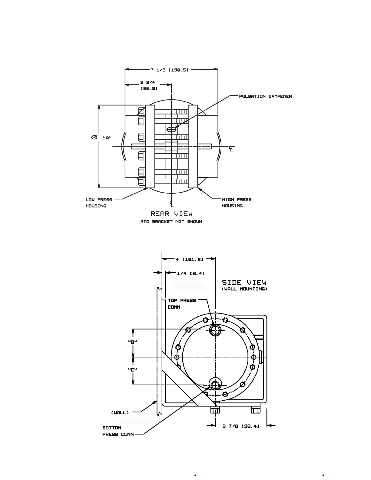
A-35
Model 199 Differential Pressure Unit (DPU) Section 6
Section 6—Dimensional Drawings
Figure 6.1—Dimensional drawing, Model 199 DPU, rear view
Figure 6.2—Dimensional drawing, Model 199 DPU, side view
Page 73

A-36
Section 6 Model 199 Differential Pressure Unit (DPU)
Table 6.1—Model 199 DPU Dimensions
Pressure Rating
psi (bar)
Dim. A
inches (mm)
Dim. B
inches (mm)
Dim. C
inches (mm)
# Bolts
1,000 (69) 6-5/8 (168.3) 2 (50.8) 2-9/64 (54.4) 12
3,000 (207) Ø 7 (177.8) 2 (50.8) 2-9/64 (54.4) 12
All Standard pipe ttings furnished by customer.
(Metric conversions are approximate.)
Page 74

Product Warranty
A. Warranty
Cameron International Corporation (“Cameron”) warrants that at the time of shipment, the
products manufactured by Cameron and sold hereunder will be free from defects in mate-
rial and workmanship, and will conform to the specications furnished by or approved by
Cameron.
B. Warranty Adjustment
1. If any defect within this warranty appears, Buyer shall notify Cameron immediately
2. Cameron agrees to repair or furnish a replacement for, but not install, any product
which within one (1) year from the date of shipment by Cameron shall, upon test and
examination by Cameron, prove defective within the above warranty.
3. No product will be accepted for return or replacement without the written authoriza-
tion of Cameron. Upon such authorization, and in accordance with instructions by
Cameron, the product will be returned shipping charges prepaid by Buyer. Replacements made under this warranty will be shipped prepaid.
C. Exclusions from Warranty
1. THE FOREGOING WARRANTY IS IN LIEU OF AND EXCLUDES ALL OTHER
EXPRESSED OR IMPLIED WARRANTIES OF MERCHANTABILITY, OR FITNESS FOR A PARTICULAR PURPOSE, OR OTHERWISE.
2. Components manufactured by any supplier other than Cameron shall bear only the
warranty made by the manufacturer of that product, and Cameron assumes no responsibility for the performance or reliability of the unit as a whole.
3. “In no event shall Cameron be liable for indirect, incidental, or consequential dam-
ages nor shall the liability of Cameron arising in connection with any products sold
hereunder (whether such liability arises from a claim based on contract, warranty, tort,
or otherwise) exceed the actual amount paid by Buyer to Cameron for the products
delivered hereunder.”
4. The warranty does not extend to any product manufactured by Cameron which has
been subjected to misuse, neglect, accident, improper installation or to use in violation
of instructions furnished by Cameron.
5. The warranty does not extend to or apply to any unit which has been repaired or
altered at any place other than at Cameron’s factory or service locations by persons
not expressly approved by Cameron.
Product Brand
Barton® is a registered trademark of Cameron International Corporation (“Cameron”).
Page 75

 Loading...