

Page 1

USER´S MANUAL
BEDIENUNGSANLEITUNG
MANUEL D`UTILISATION
MANUAL DE USUARIO
INSTRUKCJA OBSŁUGI
MANUALE D‘ USO
LED MULTI PAR
LED LIGHTING SET
CLMPAR3
1
Page 2

EN
You‘ve made the right choice!
We have designed this product to operate reliably over many years. Please read this User‘s Manual carefully, so that you can begin making optimum
use of your Cameo Light product quickly. Learn more about Cameo Light on our website WWW.CAMEOLIGHT.COM.
DE
Sie haben die richtige Wahl getroffen!
Dieses Gerät wurde unter hohen Qualitätsanforderungen entwickelt und gefertigt, um viele Jahre einen reibungslosen Betrieb zu gewährleisten.
Bitte lesen Sie diese Bedienungsanleitung sorgfältig, damit Sie Ihr neues Produkt von Cameo Light schnell und optimal einsetzen können.
Weitere Informationen über Cameo Light erhalten Sie auf unserer Website WWW.CAMEOLIGHT.COM.
FR
Vous avez fait le bon choix!
Cet appareil a été développé et fabriqué en appliquant des exigences de qualité très élevées: il garantit des années de fonctionnement sans problème.Veuillez lire attentivement ce Manuel Utilisateur : vous apprendrez rapidement à utiliser votre appareil Cameo Light de façon optimale.
Vous trouverez davantage d‘informations à propos de Cameo Light sur notre site Web: WWW.CAMEOLIGHT.COM.
ES
¡Gracias por elegir Cameo Light!
Este equipo está diseñado y fabricado con los estándares de calidad más exigentes, para garantizar un correcto funcionamiento durante muchos
años.Lea atentamente este manual de usuario para poder aprovechar rápidamente toda la funcionalidad de su nuevo producto de Cameo Light.
Más información sobre Cameo Light en la web WWW.CAMEOLIGHT.COM.
PL
Gratulujemy wyboru!
To urządzenie zostało zaprojektowane i wyprodukowane przy zastosowaniu najwyższych kryteriów jakościowych w celu zapewnienia wieloletniej
bezawaryjnej eksploatacji. Proszę starannie przeczytać niniejszą instrukcję obsługi, aby móc jak najszybciej zacząć użytkować ten produkt marki
Cameo Light. Więcej informacji na temat Cameo Light znajdą Państwo na naszej stronie internetowej pod adresem WWW.CAMEOLIGHT.COM.
IT
Avete fatto la scelta giusta!
Questo dispositivo è stato sviluppato e prodotto in conformità con elevati standard qualitativi che ne garantiscono il regolare funzionamento per molti
anni. Leggete attentamente questo manuale d‘uso per utilizzare al meglio il vostro nuovo prodotto Cameo Light. Per maggiori informazioni su Cameo
Light consultare la nostra pagina Web WWW.CAMEOLIGHT.COM.
EN
PREVENTIVE MEASURES
1. Please read these instructions carefully.
2. Keep all information and instructions in a safe place.
3. Follow the instructions.
4. Observe all safety warnings. Never remove safety warnings or other information from the equipment.
5. Use the equipment only in the intended manner and for the intended purpose.
6. Use only sufficiently stable and compatible stands and/or mounts (for fixed installations). Make certain that wall mounts are properly installed and secured.
Make certain that the equipment is installed securely and cannot fall down.
7. During installation, observ e the applicable safety regulations for your country.
8. Never install and operate the equipment near radiators, heat registers, ovens or other sources of heat. Make certain that the equipment is always
installed so that is cooled sufficiently and cannot overheat.
9. Never place sources of ignition, e.g., burning candles, on the equipment.
10. Ventilation slits must not be blocked.
11. This appliance is designed exclusively for indoor use, do not use this equipment in the immediate vicinity of water (does not apply to special outdoor equipment - in this case, observe the special instructions noted below). Do not expose this equipment to flammable materials, fluids or gases.
12. Make certain that dripping or splashed water cannot enter the equipment. Do not place containers filled with liquids, such as vases or drinking
vessels, on the equipment.
13. Make certain that objects cannot fall into the device.
14. Use this equipment only with the accessories recommended and intended by the manufacturer.
15. Do not open or modify this equipment.
16. After connecting the equipment, check all cables in order to prevent damage or accidents, e.g., due to tripping hazards.
17. During transport, make certain that the equipment cannot fall down and possibly cause property damage and personal injuries.
18. If your equipment is no longer functioning properly, if fluids or objects have gotten inside the equipment or if it has been damaged in anot her
way, switch it off immediately and unplug it from the mains outlet (if it is a powered device). This equipment may only be repaired by authorized,
qualified personnel.
19. Clean the equipment using a dry cloth.
20. Comply with all applicable disposal laws in your country. During disposal of packaging, please separate plastic and paper/cardboard.
21. Plastic bags must be kept out of reach of children.
FOR EQUIPMENT THAT CONNECTS TO THE POWER MAINS:
22. CAUTION: If the power cord of the device is equipped with an earthing contact, then it must be connected to an outlet with a protective ground.
Never deactivate the protective ground of a power cord.
23. If the equipment has been exposed to strong fluctuations in temperature (for example, after transport), do not switch it on immediately. Moisture
and condensation could damage the equipment. Do not switch on the equipment until it has reached room temperature.
24. Before connecting the equipment to the power outlet, first verify that the mains voltage and frequency match the values specified on the equipment. If the equipment has a voltage selection switch, connect the equipment to the power outlet only if the equipment values and the mains power
values match. If the included power cord or power adapter does not fit in your wall outlet, contact your electrician.
2
Page 3
25. Do not step on the power cord. Make certain that the power cable does not become kinked, especially at the mains outlet and/or power adapter
and the equipment connector.
26. When connecting the equipment, make certain that the power cord or power adapter is always freely accessible. Always disconnect the equipment from the power supply if the equipment is not in use or if you want to clean the equipment. Always unplug the power cord and power adapter
from the power outlet at the plug or adapter and not by pulling on the cord. Never touch the power cord and power adapter with wet hands.
27. Whenever possible, avoid switching the equipment on and off in quick succession because otherwise this can shorten the useful life of the
equipment.
28. IMPORTANT INFORMATION: Replace fuses only with fuses of the same type and rating. If a fuse blows repeatedly, please contact an authorised
service centre.
29. To disconnect the equipment from the power mains completely, unplug the power cord or power adapter from the power outlet.
30. If your device is equipped with a Volex power connector, the mating Volex equipment connector must be unlocked before it can be removed.
However, this also means that the equipment can slide and fall down if the power cable is pulled, which can lead to personal injuries and/or other
damage. For this reason, always be careful when laying cables.
31. Unplug the power cord and power adapter from the power outlet if there is a risk of a lightning strike or before extended periods of disuse.
32. The device must only be installed in a voltage-free condition (disconnect the mains plug from the mains).
33. Dust and other debris inside the unit may cause damage. The unit should be regularly serviced or cleaned (no guarantee) depending on ambient
conditions (dust etc., nicotine, fog) by qualified personnel to prevent overheating and malfunction.
CAUTION
RISK OF ELECTRIC SHOCK
DO NOT OPEN
The warning triangle with lightning symbol indicates dangerous uninsulated voltage inside the unit, which may cause an electrical shock.
The warning triangle with exclamation mark indicates important operating and maintenance
instructions.
CAUTION! HIGH VOLUMES IN AUDIO PRODUCTS!
This device is meant for professional use. Therefore, commercial use of this equipment is subject to the respectively applicable national accident
prevention rules and regulations. As a manufacturer, Adam Hall is obligated to notify you formally about the existence of potential health risks. Hearing damage due to high volume and prolonged exposure: When in use, this product is capable of producing high sound-pressure levels (SPL) that
can lead to irreversible hearing damage in performers, employees, and audience members. For this reason, avoid prolonged exposure to volumes in
excess of 90 dB.
CAUTION! IMPORTANT INFORMATION ABOUT LIGHTING PRODUCTS!
1. The product has been developed for professional use in the field of event technology and is not suitable as household lighting.
2. Do not stare, even temporarily, directly into the light beam.
3. Do not look at the beam directly with optical instruments such as magnifiers.
4. Stroboscope effects may cause epileptic seizures in sensitive people! People with epilepsy should definitely avoid places where strobes are used.
The product has been developed for professional use in the field of event technology and is not suitable as household lighting.
CAUTION:
To reduce the risk of electric shock, do not remove cover (or back). There are no user serviceable parts
inside. Maintenance and repairs should be exclusively carried out by qualified service personnel.
DE
SICHERHEITSHINWEISE
1. Lesen Sie diese Anleitung bitte sorgfältig durch.
2. Bewahren Sie alle Informationen und Anleitungen an einem sicheren Ort auf.
3. Befolgen Sie die Anweisungen.
4. Beachten Sie alle Warnhinweise. Entfernen Sie keine Sicherheitshinweise oder andere Informationen vom Gerät.
5. Verwenden Sie das Gerät nur in der vorgesehenen Art und Weise.
6. Verwenden Sie ausschließlich stabile und passende Stative bzw. Befestigungen (bei Festinstallationen). Stellen Sie sicher, dass Wandhalterungen
ordnungsgemäß installiert und gesichert sind. Stellen Sie sicher, dass das Gerät sicher installiert ist und nicht herunterfallen kann.
7. Beachten Sie bei der Installation die für Ihr Land geltenden Sicherheitsvorschriften.
8. Installieren und betreiben Sie das Gerät nicht in der Nähe von Heizkörpern, Wärmespeichern, Öfen oder sonstigen Wärmequellen. Sorgen Sie dafür,
dass das Gerät immer so installiert ist, dass es ausreichend gekühlt wird und nicht überhitzen kann.
9. Platzieren Sie keine Zündquellen wie z.B. brennende Kerzen auf dem Gerät.
10. Lüftungsschlitze dürfen nicht blockiert werden.
11. Das Gerät wurde ausschließlich für die Verwendung in Innenräumen entwickelt, betreiben Sie das Gerät nicht in unmittelbarer Nähe von Wasser (gilt
nicht für spezielle Outdoor Geräte - beachten Sie in diesem Fall bitte die im Folgenden vermerkten Sonderhinweise). Bringen Sie das Gerät nicht mit
brennbaren Materialien, Flüssigkeiten oder Gasen in Berührung.
12. Sorgen Sie dafür, dass kein Tropf- oder Spritzwasser in das Gerät eindringen kann. Stellen Sie keine mit Flüssigkeit gefüllten Behältnisse wie
Vasen oder Trinkgefäße auf das Gerät.
13. Sorgen Sie dafür, dass keine Gegenstände in das Gerät fallen können.
14. Betreiben Sie das Gerät nur mit dem vom Hersteller empfohlenen und vorgesehenen Zubehör.
15. Öffnen Sie das Gerät nicht und verändern Sie es nicht.
16. Überprüfen Sie nach dem Anschluss des Geräts alle Kabelwege, um Schäden oder Unfälle, z. B. durch Stolperfallen zu vermeiden.
17. Achten Sie beim Transport darauf, dass das Gerät nicht herunterfallen und dabei möglicherweise Sach- und Personenschäden verursachen kann.
18. Wenn Ihr Gerät nicht mehr ordnungsgemäß funktioniert, Flüssigkeiten oder Gegenstände in das Geräteinnere gelangt sind, oder das Gerät
3
Page 4

anderweitig beschädigt wurde, schalten Sie es sofort aus und trennen es von der Netzsteckdose (sofern es sich um ein aktives Gerät handelt).
Dieses Gerät darf nur von autorisiertem Fachpersonal repariert werden.
19. Verwenden Sie zur Reinigung des Geräts ein trockenes Tuch.
20. Beachten Sie alle in Ihrem Land geltenden Entsorgungsgesetze. Trennen Sie bei der Entsorgung der Verpackung bitte Kunststoff und Papier bzw.
Kartonagen voneinander.
21. Kunststoffbeutel müssen außer Reichweite von Kindern aufbewahrt werden.
BEI GERÄTEN MIT NETZANSCHLUSS:
22. ACHTUNG: Wenn das Netzkabel des Geräts mit einem Schutzkontakt ausgestattet ist, muss es an einer Steckdose mit Schutzleiter angeschlossen
werden. Deaktivieren Sie niemals den Schutzleiter eines Netzkabels.
23. Schalten Sie das Gerät nicht sofort ein, wenn es starken Temperaturschwankungen ausgesetzt war (beispielsweise nach dem Transport). Feuchtigkeit und Kondensat könnten das Gerät beschädigen. Schalten Sie das Gerät erst ein, wenn es Zimmertemperatur erreicht hat.
24. Bevor Sie das Gerät an die Steckdose anschließen, prüfen Sie zuerst, ob die Spannung und die Frequenz des Stromnetzes mit den auf dem Gerät
angegebenen Werten übereinstimmen. Verfügt das Gerät über einen Spannungswahlschalter, schließen Sie das Gerät nur an die Steckdose an, wenn
die Gerätewerte mit den Werten des Stromnetzes übereinstimmen. Wenn das mitgelieferte Netzkabel bzw. der mitgelieferte Netzadapter nicht in Ihre
Netzsteckdose passt, wenden Sie sich an Ihren Elektriker.
25. Treten Sie nicht auf das Netzkabel. Sorgen Sie dafür, dass spannungsführende Kabel speziell an der Netzbuchse bzw. am Netzadapter und der
Gerätebuchse nicht geknickt werden.
26. Achten Sie bei der Verkabelung des Geräts immer darauf, dass das Netzkabel bzw. der Netzadapter stets frei zugänglich ist. Trennen Sie das
Gerät stets von der Stromzuführung, wenn das Gerät nicht benutzt wird, oder Sie das Gerät reinigen möchten. Ziehen Sie Netzkabel und Netzadapter
immer am Stecker bzw. am Adapter und nicht am Kabel aus der Steckdose. Berühren Sie Netzkabel und Netzadapter niemals mit nassen Händen.
27. Schalten Sie das Gerät möglichst nicht schnell hintereinander ein und aus, da sonst die Lebensdauer des Geräts beeinträchtigt werden könnte.
28. WICHTIGER HINWEIS: Ersetzen Sie Sicherungen ausschließlich durch Sicherungen des gleichen Typs und Wertes. Sollte eine Sicherung wiederholt
auslösen, wenden Sie sich bitte an ein autorisiertes Servicezentrum.
29. Um das Gerät vollständig vom Stromnetz zu trennen, entfernen Sie das Netzkabel bzw. den Netzadapter aus der Steckdose.
30. Wenn Ihr Gerät mit einem Volex-Netzanschluss bestückt ist, muss der passende Volex-Gerätestecker entsperrt werden, bevor er entfernt werden
kann. Das bedeutet aber auch, dass das Gerät durch ein Ziehen am Netzkabel verrutschen und herunterfallen kann, wodurch Personen verletzt
werden und/oder andere Schäden auftreten können. Verlegen Sie Ihre Kabel daher immer sorgfältig.
31. Entfernen Sie Netzkabel und Netzadapter aus der Steckdose bei Gefahr eines Blitzschlags oder wenn Sie das Gerät länger nicht verwenden.
32. Das Gerät darf nur im spannungsfreien Zustand (Trennung des Netzsteckers vom Stromnetz) installiert werden.
33. Staub und andere Ablagerungen im Inneren des Geräts können es beschädigen. Das Gerät sollte je nach Umgebungsbedingungen (Staub,
Nikotin, Nebel etc.) regelmäßig von qualifiziertem Fachpersonal gewartet bzw. gesäubert werden (keine Garantieleistung), um Überhitzung und
Fehlfunktionen zu vermeiden.
CAUTION
RISK OF ELECTRIC SHOCK
DO NOT OPEN
ACHTUNG
Entfernen Sie niemals die Abdeckung, da sonst das Risiko eines elektrischen Schlages besteht. Im Inneren
des Geräts befinden sich keine Teile, die vom Bediener repariert oder gewartet werden können. Lassen Sie
Wartung und Reparaturen ausschließlich von qualifiziertem Servicepersonal durchführen.
Das gleichseitige Dreieck mit Blitzsymbol warnt vor nichtisolierten, gefährlichen Spannungen im Geräteinneren, die einen elektrischen
Schlag verursachen können.
Das gleichseitige Dreieck mit Ausrufungszeichen kennzeichnet wichtige Bedienungs- und Wartungshinweise.
ACHTUNG HOHE LAUTSTÄRKEN BEI AUDIOPRODUKTEN!
Dieses Gerät ist für den professionellen Einsatz vorgesehen. Der kommerzielle Betrieb dieses Geräts unterliegt den jeweils gültigen nationalen
Vorschriften und Richtlinien zur Unfallverhütung. Als Hersteller ist Adam Hall gesetzlich verpflichtet, Sie ausdrücklich auf mögliche Gesundheitsrisiken
hinzuweisen. Gehörschäden durch hohe Lautstärken und Dauerbelastung: Bei der Verwendung dieses Produkts können hohe Schalldruckpegel (SPL)
erzeugt werden, die bei Künstlern, Mitarbeitern und Zuschauern zu irreparablen Gehörschäden führen können. Vermeiden Sie länger anhaltende
Belastung durch hohe Lautstärken über 90 dB.
VORSICHT! WICHTIGE HINWEISE IN BEZUG AUF LICHT-PRODUKTE!
1. Das Produkt ist für den professionellen Einsatz im Bereich der Veranstaltungstechnik entwickelt worden und ist nicht für die Raumbeleuchtung in
Haushalten geeignet.
2. Blicken Sie niemals, auch nicht kurzzeitig, direkt in den Lichtstrahl.
3. Blicken Sie niemals mit optischen Geräten wie Vergrößerungsgläsern in den Lichtstrahl.
4. Stoboskopeffekte können unter Umständen bei empfindlichen Menschen epileptische Anfälle auslösen! Epilepsiekranke Menschen sollten daher
unbedingt Orte meiden, an denen Stroboskope eingesetzt werden.
Das Produkt ist für den professionellen Einsatz im Bereich der Veranstaltungstechnik entwickelt worden und ist nicht für die Raumbeleuchtung in
Haushalten geeignet.
4
Page 5

FR
MESURES PRÉVENTIVES
1. Veuillez lire attentivement ce manuel.
2. Rangez tous les documents d‘information et d‘instructions en lieu sûr.
3. Veuillez suivre toutes les instructions
4. Observez tous les messages d‘avertissement N‘enlevez pas de l‘appareil les étiquettes de sécurité ou autres informations.
5. N‘utilisez l‘appareil que pour des applications et de la façon appropriées.
6. Utilisez exclusivement des pieds et des dispositifs de fixation stables et adaptés lorsque l‘appareil est utilisé en installation fixe. Assurez-vous que les fixations murales ont été montées correctement, et qu‘elles sont sécurisées. Vérifiez que l‘appareil est installé en toute sécurité, et qu‘il ne peut pas tomber.
7. Lors de l‘installation, observez les règlementations de sécurité en vigueur dans votre pays.
8. N‘installez et n‘utilisez pas l‘appareil à proximité de radiateurs, d‘accumulateurs de chaleur, de fours ou de toute autre source de chaleur. Vérifiez
que l‘appareil est installé de façon à bénéficier en permanence d‘un refroidissement efficace et qu‘il ne peut pas chauffer de façon excessive.
9. Ne placez aucune source de flamme sur l‘appareil – par exemple, une bougie allumée.
10. Ne bloquez pas les ouïes d‘aération.
11. Cet appareil a été exclusivement conçu pour une utilisation en intérieur. N‘utilisez pas l‘appareil à proximité immédiate d‘eau (à moins qu‘il ne
s‘agisse d‘un appareil conçu pour une utilisation en extérieur – dans ce cas, respectez les instructions correspondantes ci après) Ne mettez pas
l‘appareil en contact avec des matériaux, des liquides ou des gaz inflammables.
13. Vérifiez qu‘aucun petit objet ne puisse tomber à l‘intérieur de l‘appareil.
14. N‘utilisez avec cet appareil que des accessoires recommandés et approuvés par le fabricant.
15. N‘ouvrez pas l‘appareil, et n‘essayez pas de le modifier.
16. Lors du branchement de l‘appareil, sécurisez le passage du câble secteur, afin d‘éviter tout dommage ou accident, par exemple quelqu‘un qui
trébuche sur le câble.
17. Lors du transport, vérifiez que l‘appareil ne peut tomber, ce qui pourrait provoquer des dommages matériels et/ou corporels.
18. Si votre appareil ne fonctionne plus correctement, que de l‘eau ou des objets ont pénétré à l‘intérieur, ou qu‘il a été endommagé de quelque
façon que ce soit, éteignez-le immédiatement et débranchez sa prise secteur (s‘il s‘agit d‘un appareil alimenté). Cet appareil ne doit être réparé que
par un personnel autorisé.
19. Pour le nettoyage de l‘appareil, utilisez un chiffon sec/
20. Observez toutes les réglementations en vigueur dans votre pays pour mettre l‘appareil au rebut. Lorsque vous jetez l‘emballage de l‘appareil,
veuillez séparer plastique, papier et carton.
21. Les films plastique doivent être mis hors de portée des enfants.
APPAREILS RELIÉS AU SECTEUR :
22. ATTENTION : Si le câble de l‘appareil est muni d‘un fil de terre, il doit être relié à une prise murale avec terre. Ne désactivez jamais la mise à la
terre d‘un appareil.
23. N‘allumez pas l‘appareil immédiatement s‘il a subi une grande différence de température ambiante (par exemple, lors du transport). L‘humidité
et la condensation pourraient l‘endommager. Ne mettez l‘appareil sous tension que lorsqu‘il est parvenu à la température de la pièce.
24. Avant de relier l‘appareil à la prise murale, vérifiez que la valeur et la fréquence de tension secteur sur laquelle il est réglé correspondent bien
à la valeur et à la fréquence de la tension secteur locale. Si l‘appareil possède un sélecteur de tension, ne le branchez sur la prise murale qu‘après
avoir vérifié que la valeur réglée correspond à la valeur effective de la tension secteur. Si la fiche du cordon secteur ou du bloc adaptateur livré avec
votre appareil ne correspond pas au format de votre prise murale, veuillez consulter un électricien.
25. Ne piétinez pas le câble secteur. Assurez-vous que le câble secteur n‘est pas trop pincé, notamment au niveau de l‘arrière de l‘appareil (ou de
son adaptateur secteur) et de la prise murale.
26. Lors du branchement de l‘appareil, vérifiez que l‘accès au câble secteur ou au bloc adaptateur reste facile. Sortez la fiche secteur de la prise murale
dès que vous n‘utilisez pas l‘appareil pendant un certain temps, ou si vous désirez nettoyer l‘appareil. Pour ce faire, tirez toujours sur la fiche elle-même,
ou sur le bloc secteur lui-même ; ne tirez jamais sur le câble. Ne manipulez jamais le câble secteur ou l‘adaptateur secteur avec des mains mouillées.
27. N‘éteignez/rallumez pas l‘appareil rapidement plusieurs fois de suite : vosu risquez de réduire la longévité de ses composants internes.
28. CONSEIL IMPORTANT : Ne remplacez le fusible que par un fusible de même type et du même calibre. Si le fusible fond de façon répétée, veuillez
consulter un centre de réparations agréé.
29. Pour séparer complètement l‘appareil du secteur, débranchez le cordon secteur ou l‘adaptateur de la prise murale.
30. Si votre appareil est muni d‘un connecteur secteur verrouillable (Volex), il faut d‘abord déverrouiller le mécanisme avant d‘enlever le cordon
secteur. Attention, lorsque vous retirez le câble secteur, à ne pas faire bouger l‘appareil, ce qui pourrait se traduire par un risque de chute, de blesser
quelqu‘un, ou tout autre dommage. Manipulez toujours le cordon secteur avec soin.
31. Débranchez la fiche secteur ou l‘adaptateur de la prise murale en cas d‘orage, ou si vous n‘utilisez pas l‘appareil pendant une longue période.
32. L‘appareil ne doit pas être alimenté lors de son installation (cordon secteur non relié à la prise murale).
33. Poussière et autres dépôts à l‘intérieur de l‘appareil sont susceptibles de l‘endommager. Si les conditions environnementales sont difficiles
(présence de poussière, de nicotine, de gouttelettes d‘eau...), il est recommandé de le confier à un personnel spécialisé pour entretien et nettoyage
(non pris en charge par la garantie), afin d‘éviter toute surchauffe et défaillance.
CAUTION
RISK OF ELECTRIC SHOCK
DO NOT OPEN
Le pictogramme en forme de triangle équilatéral contenant un éclair terminé d‘une flèche avertit l‘utilisateur de la présence d‘une
tension dangereuse à l‘intérieur de l‘appareil, tension susceptible de provoquer un choc électrique.
ATTENTION :
Ne démontez jamais le couvercle de l‘appareil, vous risquez de recevoir un choc électrique. L‘appareil ne
renferme aucune pièce ni composant réparable ou remplaçable par l‘utilisateur. Ne confiez l‘entretien et la
réparation qu‘à un personnel qualifié.
Le pictogramme en forme de triangle équilatéral renfermant un point d‘exclamation signale à l‘utilisateur la présence d‘instructions
importantes concernant l‘utilisation ou l‘entretien de l‘appareil.
5
Page 6

ATTENTION ! NIVEAUX SONORES ÉLEVÉS SUR LES PRODUITS AUDIO
Cet appareil a été conçu en vue d‘une utilisation professionnelle. L‘utilisation commerciale de cet appareil est soumise aux réglementations et
directives en vigueur dans votre pays en matière de prévention d‘accident. En tant que fabricant, Adam Hall est tenu de vous avertir formellement
des risques relatifs à la santé. Risques provoqués par une exposition prolongée à des niveaux sonores élevés : Lors de l‘utilisation de ce produit, il
est possible d‘atteindre des niveaux de pression sonore (exprimés en dB SPL) élevés, susceptibles de provoquer des dommages auditifs irréparables
chez les artistes, les techniciens et le public. Évitez toute exposition prolongée à des niveaux de pression sonore élevés (supérieurs à 90 dB SPL).
ATTENTION ! CONSEILS IMPORTANTS POUR LES PRODUITS D‘ÉCLAIRAGE
1. Ce produit est conçu pour une utilisation professionnelle dans le domaine du spectacle vivant : il n‘est pas prévu pour une utilisation en éclairage
domestique.
2. Ne regardez jamais directement le faisceau lumineux, même brièvement.
3. Ne regardez jamais le faisceau lumineux par l‘intermédiaire d‘un appareil optique grossissant (jumelles par exemple).
4. Dans certaines circonstances, les effets Stroboscope sont susceptibles de provoquer des crises d‘épilepsie auprès de personnes sensibles. Il est
donc conseillé aux personnes épileptiques d‘éviter les lieux où sont installés des stroboscopes.
Ce produit a été développé pour une utilisation professionnelle, dans le secteur du spectacle : il ne convient pas à l‘éclairage domestique.
ES
MEDIDAS DE SEGURIDAD
1. Lea atentamente las instrucciones de este manual.
2. Guarde toda la información en un lugar seguro para futuras consultas.
3. Siga las instrucciones indicadas.
4. Siga todas las advertencias. No quite las instrucciones de seguridad ni cualquier otra información indicada en el equipo.
5. Utilice el equipo únicamente según la finalidad prevista.
6. Utilice solo soportes y fijaciones que sean robustos y adecuados cuando instale el equipo en instalaciones fijas. Asegúrese de que los soportes de
pared están correctamente instalados y firmemente fijados. Asegúrese de que el equipo está sólidamente instalado y no se puede caer.
7. Al instalar el equipo, respete las normas de seguridad aplicables en su país.
8. Evite instalar el equipo cerca de radiadores, acumuladores de calor, estufas o cualquier otra fuente de calor. Asegúrese de que el equipo esté instalado en
un lugar con ventilación suficiente para evitar cualquier sobrecalentamiento.
9. No coloque sobre el equipo fuentes de llamas sin protección, por ejemplo, velas encendidas.
10. Evite bloquear las rejillas de ventilación.
11. El equipo está diseñado para uso en interiores; no lo utilice cerca del agua (excepto los equipos específicamente diseñados para uso en exterior,
en cuyo caso tenga en cuenta las indicaciones mencionadas a continuación). No exponga este equipo a materiales, líquidos o gases inflamables.
12. Evite exponer el equipo a gotas o salpicaduras que puedan caer dentro del mismo. No coloque recipientes llenos de líquido, como floreros o
vasos, sobre el equipo.
13. Asegúrese de no dejar caer ningún objeto dentro del equipo.
14. Emplee el equipo únicamente con los accesorios recomendados por el fabricante.
15. No abra el equipo ni intente modificarlo.
16. Una vez conectado el equipo, compruebe que en toda la longitud del cableado no hay peligro de que provoque una caída, por ejemplo.
17. Durante el transporte, asegúrese de que el equipo no se caiga y pueda causar daños personales o materiales.
18. Si el equipo no funciona correctamente, o si se ha vertido líquido sobre él, o si un objeto ha caído en su interior o si ha sufrido algún desperfecto,
apague inmediatamente el equipo y desenchufe el cable eléctrico (si se trata de un equipo activo). Únicamente un técnico especialista debe reparar
el equipo.
19. Para limpiar el equipo utilice un paño seco.
20. Procure seguir las normas vigentes en su país sobre reciclaje de desechos. Separe los componentes de plástico, papel y cartón del paquete para
reciclarlos en sus contenedores respectivos.
21. No deje las bolsas de plástico al alcance de los niños.
PARA LOS EQUIPOS CON TOMA ELÉCTRICA:
22. ADVERTENCIA: Si el cable eléctrico está provisto de un contacto de protección, debe conectarse a una toma eléctrica con conexión a tierra. No
desactivar nunca esta conexión de protección a tierra del cable eléctrico.
23. Si el equipo ha estado expuesto a un cambio brusco de temperatura (por ejemplo, después del transporte), no lo encienda inmediatamente. La
condensación o la humedad podrían dañar el equipo. Deje que el equipo alcance la temperatura ambiente antes de encenderlo.
24. Antes de conectar el cable eléctrico a la toma de corriente, compruebe si la tensión y la frecuencia del suministro eléctrico coinciden con las
especificaciones de este equipo. Si el equipo dispone de un selector de tensión, antes de enchufarlo a la red eléctrica, asegúrese de que el valor seleccionado coincide con la tensión de suministro. Si el enchufe o el adaptador de corriente no encajan en la toma eléctrica, consulte a un electricista.
25. Asegúrese de que el cable eléctrico no está pinzado. Evite que el cable resulte pellizcado, sobre todo en los extremos de conexión al equipo y en
la toma eléctrica.
26. Al conectar el equipo, asegúrese de que el cable eléctrico o el adaptador de corriente estén siempre accesibles. Desconecte el equipo de la toma
de corriente cuando no esté en uso o antes de limpiarlo. Para ello, desconecte el cable eléctrico y el adaptador de corriente del conector del equipo
en vez de desenchufar el cable de la toma eléctrica. No tocar el cable eléctrico ni el adaptador de corriente con las manos húmedas.
27. No encienda y apague el equipo en cortos intervalos de tiempo, ya que se reduce así la vida útil del sistema.
28. NOTA IMPORTANTE: Sustituya los fusibles únicamente por otros del mismo tipo y de las mismas características. Si el fusible se funde continuamente, póngase en contacto con un servicio técnico autorizado.
29. Para desconectar completamente el equipo de la tensión eléctrica, desenchufe el cable eléctrico o el adaptador de corriente de la toma eléctrica.
30. Si el equipo dispone de un enchufe eléctrico Volex, deberá desbloquearse el Volex del equipo para desenchufarlo. Esto implica que un tirón en el
cable eléctrico puede desplazar el equipo y provocar daños personales o materiales. Por tanto, asegúrese de instalar los cables con sumo cuidado.
31. Si es probable que caiga un rayo por una tormenta eléctrica o si no va a emplear el equipo durante mucho tiempo, desenchufe el cable eléctrico
y el adaptador de corriente.
6
Page 7
32. Al montar el equipo, asegúrese de que no está alimentado eléctricamente (el enchufe no debe estar conectado a la red eléctrica).
33. La acumulación de polvo y otras partículas en el interior del equipo puede causar daños. Dependiendo de las condiciones ambientales (polvo,
nicotina, niebla, etc.), deberá realizarse periódicamente el mantenimiento o la limpieza del equipo por personal especializado, para evitar cualquier
sobrecalentamiento o fallo de funcionamiento (mantenimiento y limpieza no cubiertos por la garantía).
CAUTION
RISK OF ELECTRIC SHOCK
DO NOT OPEN
El símbolo de rayo dentro de un triángulo equilátero advierte al usuario de la presencia de tensiones peligrosas sin aislamiento dentro
del equipo que pueden causar una descarga eléctrica.
El símbolo de exclamación dentro de un triángulo equilátero advierte al usuario de la existencia de importantes instrucciones de uso y
mantenimiento.
¡ADVERTENCIA: ALTO VOLUMEN!
Este equipo se destina a un uso profesional. Por consiguiente, si se aplica a un uso comercial, estará sujeto a las normas y reglamentos de la
Asociación para la prevención de accidentes de su sector profesional. Como fabricante, Adam Hall tiene la obligación de informar formalmente a los
usuarios de la existencia de posibles riesgos para la salud. Daños auditivos por exposición prolongada a un nivel SPL alto: este equipo puede generar
fácilmente un nivel de presión sonora (SPL) lo suficientemente elevado como para causar daños auditivos permanentes a los artistas, el personal de
producción y el público. Deben tomarse precauciones para evitar la exposición prolongada a un SPL de más de 90dB.
¡ATENCIÓN: INFORMACIÓN IMPORTANTE SOBRE LOS PRODUCTOS DE ILUMINACIÓN!
1. Este producto ha sido desarrollado para uso profesional en el sector de eventos y no está diseñado para la iluminación doméstica.
2. No mire directamente el haz de luz, ni siquiera momentáneamente.
3. No mire directamente el haz de luz con instrumentos ópticos, como lentes de aumento.
4. ¡Los efectos estroboscópicos pueden a veces causar convulsiones en personas fotosensibles! Las personas con epilepsia deben evitar los lugares
en los que se usan luces estroboscópicas.
Este producto ha sido desarrollado para uso profesional en el sector de eventos y no está diseñado para la iluminación doméstica.
PL
ŚRODKI OSTROŻNOŚCI
1. Należy dokładnie przeczytać niniejszą instrukcję.
2. Wszystkie informacje i instrukcje przechowywać w bezpiecznym miejscu.
3. Należy przestrzegać zaleceń.
4. Należy przestrzegać wszystkich wskazówek ostrzegawczych. Nie wolno usuwać wskazówek bezpieczeństwa ani innych informacji znajdujących
się na urządzeniu.
5. Używać urządzenia wyłącznie w sposób zgodny z jego przeznaczeniem.
6. Stosować wyłącznie stabilne i pasujące statywy, ew. elementy mocujące (w przypadku instalacji stałych). Należy zadbać o prawidłową instalację
uchwytów ściennych i ich odpowiednie zabezpieczenie. Zapewnić bezpieczną instalację urządzenia i upewnić się, że urządzenie nie spadnie.
7. Podczas instalacji przestrzegać obowiązujących w danym kraju przepisów bezpieczeństwa.
8. Urządzenie instalować i eksploatować z dala od grzejników, zasobników ciepła, pieców i innych źródeł ciepła. Zadbać o zainstalowanie urządzenia w taki
sposób, aby zawsze było ono wystarczająco chłodzone i nie mogło ulec przegrzaniu.
9. Nie umieszczać na urządzeniu źródeł zapłonu, takich jak np. palące się świece.
10. Nie wolno blokować szczelin wentylacyjnych.
11. Urządzenie zostało zaprojektowane wyłącznie do użytku w pomieszczeniach. Nie używać urządzenia w bezpośrednim sąsiedztwie wody (nie
dotyczy specjalnych urządzeń do stosowania na zewnątrz – w takim przypadku należy przestrzegać podanych poniżej wskazówek specjalnych).
Urządzenie nie może mieć kontaktu z palnymi materiałami, płynami ani gazami.
12. Zabezpieczyć urządzenie przed wniknięciem kapiącej lub pryskającej wody. Nie wolno stawiać na urządzeniu pojemników napełnionych płynami,
takich jak wazony czy naczynia z piciem.
13. Należy zadbać o to, aby do urządzenia nie wpadały żadne przedmioty.
14. Urządzenie można eksploatować tylko przy użyciu akcesoriów zalecanych i przewidzianych przez producenta.
15. Nie otwierać urządzenia ani nie dokonywać w nim zmian.
16. Po podłączeniu urządzenia sprawdzić wszystkie ciągi kablowe, aby zapobiec szkodom lub wypadkom np. w wyniku potknięcia.
17. Podczas transportu zadbać o to, aby urządzenie nie upadło, gdyż może to spowodować uszkodzenie mienia i obrażenia ciała.
18. Jeśli urządzenie nie działa prawidłowo, do jego wnętrza dostały się płyny lub przedmioty lub jeśli urządzenie zostało uszkodzone w inny sposób,
należy je natychmiast wyłączyć i odłączyć od gniazda sieciowego (jeśli urządzenie jest aktywne). Naprawę takiego urządzenia może wykonać tylko
autoryzowany personel specjalistyczny.
19. Do czyszczenia urządzenia stosować suchą ściereczkę.
20. Przestrzegać obowiązujących w danym kraju przepisów dotyczących usuwania odpadów. Podczas utylizacji opakowania oddzielić tworzywo
sztuczne od papieru i tektury.
21. Worki z tworzywa sztucznego należy przechowywać w miejscu niedostępnym dla dzieci.
DOTYCZY URZĄDZEŃ Z ZASILANIEM SIECIOWYM:
22. UWAGA: jeśli kabel sieciowy urządzenia jest wyposażony w zestyk ochronny, należy go podłączyć do gniazda z przewodem uziemiającym. Nigdy
nie wolno dezaktywować przewodu uziemiającego kabla sieciowego.
ATENCIÓN:
Para evitar el riesgo de descarga eléctrica, no retire la tapa. El equipo no contiene elementos que el
usuario pueda reparar o sustituir. Para cualquier tarea de mantenimiento o reparación, acuda a un técnico
cualificado.
7
Page 8
23. Nie włączać urządzenia bezpośrednio po narażeniu go na silne wahania temperatury (np. po transporcie). Wilgoć i skropliny mogą uszkodzić
urządzenie. Włączyć urządzenie dopiero wtedy, gdy osiągnie temperaturę pokojową.
24. Przed podłączeniem urządzenia do gniazda elektrycznego należy sprawdzić, czy napięcie i częstotliwość sieci elektrycznej odpowiada
wartościom podanym na urządzeniu. Jeśli urządzenie jest wyposażone w przełącznik napięcia, należy podłączyć je do gniazda tylko wówczas,
gdy wartości urządzenia odpowiadają wartościom sieci elektrycznej. Jeśli dołączony kabel sieciowy lub dołączony adapter sieciowy nie pasuje do
gniazda elektrycznego, należy skontaktować się z elektrykiem.
25. Nie stawać na kablu sieciowym. Należy zadbać o to, aby kable przewodzące napięcie nie były zagięte przy gnieździe sieciowym, przy adapterze
sieciowym ani przy gnieździe urządzenia.
26. Przy podłączaniu urządzenia zawsze należy zadbać o to, aby kabel sieciowy lub adapter sieciowy był zawsze łatwo dostępny. Odłączyć
urządzenie od źródła zasilania, gdy nie jest ono używane lub gdy ma zostać poddane czyszczeniu. Zawsze należy wyjmować kabel sieciowy i adapter
sieciowy z gniazda, chwytając za wtyczkę lub adapter, a nie za kabel. Nigdy nie dotykać kabla sieciowego i adaptera sieciowego mokrymi dłońmi.
9. W miarę możliwości nie włączać i wyłączać urządzenia w krótkich odstępach czasu, gdyż może to mieć negatywny wpływ na jego żywotność.
28. WAŻNA INFORMACJA: bezpieczniki należy wymieniać wyłącznie na bezpieczniki tego samego typu i o takich samych wartościach. Jeśli bezpiecznik stale się
przepala, należy skontaktować się z autoryzowanym centrum serwisowym.
29. Aby całkowicie odłączyć urządzenie od sieci, należy wyjąć kabel sieciowy lub adapter sieciowy z gniazda.
30. Jeśli urządzenie jest wyposażone w przyłącze sieciowe Volex, konieczne jest odblokowanie odpowiedniej wtyczki urządzenia Volex, zanim
będzie możliwe jej odłączenie. Oznacza to także, iż w wyniku pociągnięcia za kabel urządzenie może się przesunąć i spaść, co może spowodować
obrażenia ciała i/lub inne szkody, dlatego ważne jest, aby przewody były odpowiednio poprowadzone.
31. W przypadku zagrożenia uderzeniem pioruna lub jeśli urządzenie przez dłuższy czas nie jest używane, należy wyjąć kabel sieciowy i adapter
sieciowy z gniazda.
32. Instalacja urządzenia powinna odbywać się, gdy urządzenie nie jest podłączone do źródła zasilania (należy wyjąć wtyczkę z gniazda).
33. Kurz i inne osady wewnątrz urządzenia mogą je uszkodzić. W zależności od warunków otoczenia (kurz, nikotyna, opary itp.) urządzenie powinno być
konserwowane lub czyszczone przez wykwalifikowanego specjalistę (usługa nieobjęta gwarancją), aby zapobiec przegrzaniu i nieprawidłowemu działaniu.
CAUTION
RISK OF ELECTRIC SHOCK
DO NOT OPEN
Trójkąt równoboczny z symbolem błyskawicy sygnalizuje nieizolowane, niebezpieczne napięcie we wnętrzu urządzenia, które może
spowodować porażenie prądem.
Trójkąt równoboczny z wykrzyknikiem oznacza ważne wskazówki dotyczące obsługi i konserwacji.
UWAGA:
Nigdy nie zdejmować pokrywy, gdyż grozi to porażeniem prądem. We wnętrzu urządzenia nie ma żadnych
części, które mogłyby zostać naprawione bądź poddane czynnościom konserwacyjnym przez użytkownika.
Czynności konserwacyjne i naprawy może przeprowadzać wyłącznie wykwalifikowany personel serwisowy.
UWAGA! WYSOKI POZIOM GŁOŚNOŚCI PRODUKTÓW AUDIO!
To urządzenie przewidziane jest do zastosowań profesjonalnych. Komercyjne stosowanie tego urządzenia podlega obowiązującym w danym kraju
przepisom i wytycznym dotyczącym zapobiegania wypadkom. Firma Adam Hall jest jako producent zobowiązana do wyraźnego informowania o
potencjalnym zagrożeniu dla zdrowia. Utrata słuchu w wyniku wysokiego poziomu głośności i długotrwałego narażenia: podczas stosowania tego
produktu może powstać wysoki poziom ciśnienia akustycznego (SPL), który może doprowadzić do nieodwracalnego uszkodzenia słuchu u artystów,
pracowników i widzów. Należy unikać długotrwałego narażenia na wysoki poziom głośności powyżej 90 dB.
OSTROŻNIE! WAŻNE WSKAZÓWKI DOTYCZĄCE PRODUKTÓW OŚWIETLENIOWYCH!
1. Produkt przeznaczony jest do zastosowań profesjonalnych podczas organizacji imprez i nie nadaje się do oświetlania pomieszczeń w gospodarstwie domowym.
2. Nigdy nie spoglądać bezpośrednio w stronę promienia świetlnego, nawet przez krótką chwilę.
3. Nigdy nie spoglądać w stronę promienia świetlnego przy pomocy urządzeń optycznych, takich jak np. szkło powiększające.
4. Efekty stroboskopowe mogą wywołać ataki epilepsji u osób wrażliwych na pulsujące światło! Dlatego osoby chorujące na epilepsję powinny
unikać miejsc, w których stosowane są stroboskopy.
Produkt powstal z mysla o profesjonalnych zastosowaniach w branzy estradowej i nie jest przeznaczony do oswietlania pomieszczen w gospodarstwach
domowych.
IT
MISURE PRECAUZIONALI
1. Lesen S1. Leggere attentamente il presente manuale di istruzioni.
2. Conservare tutte le indicazioni e le istruzioni in un luogo sicuro.
3. Seguire le istruzioni.
4. Rispettare tutte le avvertenze. Non rimuovere dal dispositivo le indicazioni sulla sicurezza o altre informazioni.
5. Utilizzare il dispositivo solo nei modi previsti dal manuale.
6. Utilizzare esclusivamente stativi e fissaggi stabili e adatti (per installazioni fisse). Verificare che i supporti a parete siano installati e fissati a regola
d‘arte. Verificare che il dispositivo sia installato in modo stabile e non possa cadere.
7. Durante l‘installazione, osservare le normative sulla sicurezza in vigore nel proprio Paese.
8. Non installare né azionare il dispositivo in prossimità di radiatori, accumulatori termici, stufe o altre fonti di calore. Accertarsi che il dispositivo sia sempre
installato in modo che venga raffreddato a sufficienza e non possa surriscaldarsi.
9. Non appoggiare sul dispositivo fonti di combustione, quali candele accese.
10. Le fessure di areazione non devono essere bloccate.
11. Il dispositivo è destinato all‘impiego esclusivamente in ambienti chiusi; non deve essere utilizzato nelle immediate vicinanze di acqua (questo
8
Page 9
punto non interessa i dispositivi specifici per l‘esterno, per i quali valgono le indicazioni speciali riportate di seguito). Non portare mai il dispositivo a
contatto con materiali, liquidi o gas infiammabili.
12. Accertarsi che all‘interno del dispositivo non possa penetrare acqua per gocciolamento o spruzzo. Non collocare sul dispositivo oggetti contenenti
liquidi, quali vasi, tazze o bicchieri.
13. Assicurarsi che non sia possibile la caduta di oggetti nel dispositivo.
14. Azionare il dispositivo esclusivamente con gli accessori appositamente consigliati e previsti dal produttore.
15. Non aprire né modificare il dispositivo.
16. Una volta collegato il dispositivo, verificare tutti i cavi per evitare danni o incidenti, ad esempio per inciampo.
17. Durante il trasporto, assicurarsi che il dispositivo non possa cadere e causare possibili danni a cose e/o persone.
18. Se il dispositivo non funzionasse più correttamente, vi fosse caduto sopra del liquido o un oggetto o fosse stato danneggiato in altro modo, spegnerlo immediatamente e staccare la spina (se si tratta di un dispositivo attivo). La riparazione del dispositivo deve essere affidata esclusivamente a
personale qualificato autorizzato.
19. Per la pulizia del dispositivo utilizzare un panno pulito.
20. Rispettare le leggi sullo smaltimento in vigore nel Paese di installazione. Al momento di smaltire l‘imballo, separare la plastica dalla carta e dal
cartone.
21. I sacchetti di plastica devono essere tenuti lontani dalla portata dei bambini.
DISPOSITIVI CON ALLACCIAMENTO DI RETE:
22. ATTENZIONE: se il cavo di rete è dotato di contatto di protezione, deve essere collegato a una presa di rete con messa a terra. Non disattivare mai
la connessione di messa a terra di un cavo di rete.
23. Non accendere il dispositivo subito dopo essere stato sottoposto a forti variazioni di temperatura (ad esempio dopo il trasporto). Umidità e
condensa potrebbero danneggiare il dispositivo. Accendere il dispositivo solo dopo che ha raggiunto la temperatura ambiente.
24. Prima di collegare il dispositivo alla presa, controllare innanzitutto se la tensione e la frequenza della rete elettrica coincidono con i valori indicati
sul dispositivo stesso. Nel caso di dispositivo munito di selettore di tensione, collegarlo alla presa unicamente se i valori del dispositivo coincidono
con quelli della rete elettrica. Se il cavo di rete o l‘adattatore di rete forniti in dotazione non sono compatibili con la presa, rivolgersi a un elettricista.
25. Non calpestare il cavo di rete. Accertarsi che i cavi sotto tensione, in particolare della presa di rete o dell‘adattatore di rete, non vengano pizzicati.
26. Durante il cablaggio del dispositivo, verificare sempre che il cavo di rete e l‘adattatore di rete siano costantemente accessibili. Staccare sempre
il dispositivo dall‘alimentazione di rete quando non è utilizzato o durante la pulizia. Per staccare dalla presa il cavo di rete e l‘adattatore di rete, tirare
sempre dalla spina o dall‘adattatore e non dal cavo. Non toccare mai il cavo di alimentazione e l’alimentatore con le mani umide.
27. Evitare per quanto possibile di accendere e spegnere velocemente il dispositivo per non pregiudicarne la durata.
28. NOTA IMPORTANTE: Sostituire i fusibili esclusivamente con fusibili dello stesso tipo e valore. Se un fusibile continua a saltare, rivolgersi a un
centro di assistenza autorizzato.
29. Per staccare completamente il dispositivo dalla rete elettrica, rimuovere il cavo di rete o l‘adattatore di rete dalla presa.
30. Per staccare un dispositivo provvisto di presa Volex, è prima necessario sbloccare la relativa spina Volex del dispositivo stesso. Tirando il cavo di
rete, però, il dispositivo potrebbe spostarsi e cadere, provocando danni alle persone o di altro genere. Prestare quindi la più scrupolosa attenzione
durante la posa dei cavi.
31. In caso di pericolo di caduta di fulmine, o se il dispositivo rimane inutilizzato a lungo, staccare sempre il cavo di rete e l‘adattatore di rete dalla presa.
32. L‘installazione del dispositivo deve essere realizzata unicamente in assenza di tensione (staccare la spina dalla rete elettrica).
33. Polvere e depositi di altra natura all‘interno del dispositivo possono danneggiarlo. A seconda delle condizioni ambientali (polvere, nicotina,
nebbia ecc.) il dispositivo deve essere sottoposto a regolari interventi di manutenzione e pulizia da parte di personale specializzato (senza garanzia,
interventi a carico del proprietario) per evitare surriscaldamento e malfunzionamenti.
CAUTION
RISK OF ELECTRIC SHOCK
DO NOT OPEN
ATTENZIONE:
non togliere mai il coperchio di protezione perché sussiste il pericolo di scosse elettriche. L‘interno del dispositivo non contiene parti che possono essere riparate o sottoposte a manutenzione da parte dell‘utente.
Per gli interventi di manutenzione e di riparazione rivolgersi esclusivamente a personale qualificato.
Il triangolo equilatero con il simbolo del lampo segnala la presenza di tensioni pericolose non isolate all‘interno dell‘apparecchio che
possono causare scosse elettriche.
Il triangolo equilatero con punto esclamativo segnala la presenza di importanti informazioni relative all’uso e alla manutenzione.
ATTENZIONE! PRODOTTI AUDIO con LIVELLI SONORI ELEVATI!
Questo dispositivo è destinato a uso professionale. Il suo utilizzo in ambito commerciale è soggetto alle normative e alle direttive nazionali vigenti in
materia di prevenzione di infortuni. In qualità di produttore, Adam Hall è tenuto per legge a informare espressamente gli utenti degli eventuali rischi
per la salute. Danni all‘udito provocati da un’esposizione prolungata a un livello sonoro elevato: l‘utilizzo di questo prodotto può generare elevati
livelli di pressione sonora (SPL) che possono provocare danni irreparabili all‘udito di artisti, collaboratori e spettatori. Evitare l‘esposizione prolungata
a livelli sonori elevati, superiori a 90dB.
ATTENZIONE! INDICAZIONI IMPORTANTI RELATIVE AI PRODOTTI DI ILLUMINAZIONE!
1. Il prodotto è stato sviluppato per un uso professionale nel settore della tecnologia applicata a spettacoli e non è idoneo all‘impiego
nell‘illuminazione domestica.
2. Non fissare mai direttamente il fascio di luce, nemmeno per brevi istanti.
3. Non guardare mai il fascio di luce con dispositivi ottici quali le lenti d‘ingrandimento.
4. In alcuni casi, in persone sensibili gli effetti stroboscopici possono causare attacchi epilettici! Le persone affette da epilessia devono perciò
assolutamente evitare luoghi in cui vengono impiegati effetti stroboscopici.
Il prodotto è stato sviluppato per un uso professionale nella tecnologia applicata a spettacoli e non è idoneo all‘impiego nell‘illuminazione domestica.
9
Page 10

INTRODUCTION / EINFÜHRUNG / INTRODUCTION / INTRODUCCIÓN / WPROWADZENIE /
INTRODUZIONE
EN
Introduction
The Cameo CLMPAR3 is an especially compact and flexible lighting system for professional requirements with maximum brightness and perfect RGBW
colour mixing. Equipped with completely redesigned software and practically oriented programs, this light, portable complete solution has extensive
control capabilities in DMX and stand-alone mode.
The four flat PAR floodlights, each with seven ultrabright 8W quad LEDs and 25° beam angle, are convection cooled and mounted on a bar with integral
controls and all connectors so that they are individually aimable. Neutrik PowerCon sockets are used for power supply and passing on incoming power;
external components can be powered via two safety plug sockets that are switchable by remote control. The lighting system is controlled via DMX, the
included IR remote control, an optional foot pedal or the clearly arranged, illuminated LC display with four function keys.
Thanks to seven selectable DMX modes and the wide range of functions even in stand-alone mode, the Cameo CLMPAR3 is the optimal all-in-one
system for expressive lighting design in mobile applications and fixed installations.
DE
Einführung
Die Cameo CLMPAR3 ist eine besonders kompakte und flexible Lichtanlage für professionelle Ansprüche mit höchster Leuchtkraft und perfekter RGBWFarbmischung. Mit völlig neu konzipierter Software und praxisorientierten Programmen ausgestattet, verfügt die leicht transportierbare Komplettlösung
über umfangreiche Steuerungsmöglichkeiten im DMX- und Standalone-Modus.
Die vier flachen PAR-Scheinwerfer mit je sieben ultrahellen 8W Quad-LEDs und 25° Abstrahlwinkel sind konvektionsgekühlt und individuell ausrichtbar
an einem Träger mit integrierter Steuerung und allen Anschlüssen montiert. Zur Stromzufuhr und -weiterleitung dienen Neutrik Powercon-Buchsen,
externe Komponenten können über zwei per Fernbedienung schaltbare Schutzkontaktstecker-Buchsen versorgt werden. Die Steuerung erfolgt über
DMX, die mitgelieferte IR Fernbedienung, ein optionales Fußpedal, oder über das übersichtliche, beleuchtete LC-Display mit vier Funktionstasten.
Durch sieben wählbare DMX-Modi und die große Vielfalt an Funktionen auch im Standalone-Betrieb ist die Cameo CLMPAR3 die optimale All-In-OneAnlage für ausdrucksstarkes Lichtdesign im mobilen wie im Installationsbereich.
FR
Introduction
Le Cameo CLMPAR3 est un set de projecteurs PAR à LED compact et d’une grande souplesse, convenant à des applications professionnelles exigeant
une excellente luminosité et un mélange de couleurs RGBW de qualité parfaite. Le CLMPAR3 est équipé d’un tout nouveau logiciel et de programmes
développés dans une optique pratique avant tout. Il constitue une solution complète, facile à transporter, dotée de nombreuses possibilités de pilotage
DMX, et utilisable en mode autonome.
Ses quatre projecteurs PAR, de profondeur réduite, possèdent chacun 7 LED quadricolores d’une puissance de 8 W, extrêmement lumineuses, d’un
angle de départ de 25°. Le refroidissement s’effectue par convexion ; chacun des projecteurs se règle indépendamment en orientation depuis son support, qui intègre les circuits électroniques de pilotage et tous les connecteurs. L’alimentation et le renvoi secteur s’effectuent sur connecteurs Neutrik
Powercon, et les composants externes peuvent se brancher sur deux prises fiche avec prise de terre commutables par télécommande. Le pilotage
s’effectue via DMX, la télécommande infrarouge livrée, un pédalier optionnel ou l’écran LCD rétro-éclairé, bien lisible, pourvu de 4 touches de fonction.
Grâce aux 7 modes DMX commutables et aux nombreuses fonctions disponibles même en mode autonome (Standalone), le Cameo CLMPAR3 constitue
une solution «tout en un» optimale pour vos besoins d’éclairage avec une luminosité exceptionnelle, tant en installation fixe que mobile.
ES
Introducción
El CLMPAR3 de Cameo es un set de proyectores muy compacto y flexible para aplicaciones profesionales, que ofrece una intensidad impresionante
y una perfecta mezcla de colores RGBW. Equipado con un nuevo software y prácticos programas, ofrece una solución completa, fácil de transportar y
con diversas posibilidades de control en los modos DMX y Autónomo.
Los cuatro focos PAR planos provistos de siete LEDs ultrabrillantes de 8 W y cuatro colores ofrecen un ángulo de dispersión de 25°, se enfrían por
convección, se ajustan individualmente y están montados en una barra que integra un controlador y todas las conexiones. Para la entrada y salida
de la alimentación eléctrica, dispone de conectores Neutrik PowerCon, y pueden enchufarse dos focos externos a dos bases enchufe con toma de
tierra conmutables. El control se realiza por DMX, por medio del mando a distancia por infrarrojos suministrado, un pedal opcional o la pantalla LCD
retroiluminada con cuatro botones. Gracias a sus siete modos DMX seleccionables y la amplia variedad de funciones en modo Autónomo, el CLMPAR3
de Cameo es el sistema de iluminación todo en uno ideal para crear efectos impactantes en instalaciones móviles y fijas.
PL
Wprowadzenie
Cameo CLMPAR3 to wyjątkowo kompaktowa i wielofunkcyjna instalacja oświetleniowa do profesjonalnych zastosowań, oferująca najwyższą zdolność
oświetleniową oraz perfekcyjne mieszanie barw RGBW. To wygodne w transporcie, kompletne rozwiązanie zostało wyposażone w całkowicie nową
koncepcję oprogramowania i praktyczne programy umożliwiające kompleksowe sterowanie w trybie DMX i Standalone.
Cztery płaskie reflektory PAR, każdy złożony z siedmiu bardzo jasnych diod LED 8 W Quad o kącie wiązki światła wynoszącym 25°, posiadają chłodzenie konwekcyjne oraz możliwość indywidualnego ustawienia na listwie wyposażonej w zintegrowane sterowanie i wszystkie przyłącza. Dopływ i
przesyłanie prądu zapewniają gniazda Neutrik PowerCON, elementy zewnętrzne mogą być także zasilane z dwóch włączanych za pomocą pilota gniazd
wtyczka z uziemieniem. Do sterowania służy złącze DMX, załączony pilot na podczerwień, opcjonalny pedał nożny lub wyraźny, podświetlany ekran
LCD z czterema przyciskami funkcyjnymi. Jako urządzenie oferujące siedem trybów DMX do wyboru oraz szereg funkcji w trybie Standalone system
reflektorów Cameo CLMPAR3 jest optymalnym rozwiązaniem wielofunkcyjnym do ekspresyjnego operowania światłem w instalacjach przenośnych
i stałych.
10
Page 11

IT
Introduzione
Cameo CLMPAR3 è un impianto d’illuminazione particolarmente compatto e flessibile per esigenze professionali, dotato di elevata potenza e una
perfetta miscelazione del colore RGBW. Grazie al suo software di nuova concezione e ad i suoi programmi orientati alla prassi, questa soluzione
completa facilmente trasportabile dispone di numerose possibilità di controllo, sia in modalità DMX che standalone.
I quattro fari piatti PAD, ognuno dotato di sette LED Quad ultrachiari da 8W e con angolo di proiezione di 25°, sono raffreddati a convezione e
orientabili individualmente su un supporto con controlli integrati e tutti i collegamenti montati. Per l’alimentazione e la trasmissione di corrente, sono
presenti delle prese Neutrik Powercon; i componenti esterni possono essere alimentati tramite due prese spina tedesca telecomandabili. Il comando
avviene tramite DMX, il telecomando IR incluso, una pedaliera opzionale, oppure con il display LCD illuminato con quattro pulsanti.
Con sette modalità DMX ed un’ampia gamma di funzioni, anche in modalità standalone, Cameo CLMPAR3 è l’impianto tutto-in-uno ideale per creare
luci ad effetto in ambiti mobili o su impianti.
EN
LED MULTI PAR LIGHTING SYSTEM
CLMPAR3
CONTROL FUNCTIONS
4-channel-1, 4-channel-2, 6-channel, 8-channel, 9-channel, 16-channel, 21-channel DMX control, Separate control of the red, green, and blue LEDs.
FEATURES
4 x 7 bright QUAD-colour LEDs (8W) with 25° beam angle, Music control via built-in microphone, Colour change rate and stroboscope effect controllable via control panel, DMX, and remote control, Multicolour colour change, Master/slave functionality, Rugged, flat housing, Power consumption:
210 W, Absolutely silent thanks to convection cooling, Long life LEDs with especially long service life, Lighted multifunctional LC display, 2 additional
external lights mountable on bar, Power supplied to the external lights via 2 separate, switchable safety plug power outlets, 28 mm TV spigots,
Multifunctional infrared remote control included, Remote control via 4-way foot switch (CLMPARFOOT2, optional), Transport case included.
OPERATION
The Cameo CLMPAR3 is a DMX-512 controllable LED lighting system with RGBW colour mixing that stands out because of highly efficient, especially
bright LEDs. The intensity of the four colour groups (red, green, blue, white) can be controlled independently of one another, thus permitting an
unlimited number of different colours. The Cameo multi PAR LED lighting system can be used as a stand-alone unit, via IR remote control and foot
switch, and also in master/slave mode, with music control, and via DMX-512 protocol.
DE
LED MULTIPAR LICHTANLAGE
CLMPAR3
STEUERUNGSFUNKTIONEN
4-Kanal-1, 4-Kanal-2, 6-Kanal, 8-Kanal, 9-Kanal, 16-Kanal und 21-Kanal DMX-Steuerung, Separate Steuerung der LEDs Rot, Grün, Blau und Weiß.
EIGENSCHAFTEN
4 x 7 leuchtstarke QUAD-Colour-LEDs (8W) mit 25° Abstrahlwinkel, Musiksteuerung über eingebautes Mikrofon, Farbwechselgeschwindigkeit und
Stroboskopeffekt über Bedienpanel, DMX und Fernbedienung steuerbar, Multicolor-Farbwechsel, Master/Slave-Funktionalität, Robuste, flache Gehäuse, Leistungsaufnahme: 210 W, Konvektionskühlung, dadurch absolut geräuschlos, Longlife-LEDs mit besonders langer Lebensdauer, Beleuchtetes,
multifunktionales LC-Display, 2 zusätzliche externe Strahler auf der Traverse montierbar, Stromversorgung der externen Strahler über 2 separate,
schaltbare Schutzkontaktstecker Steckdosen, 28 mm TV-Zapfen, Multifunktionale Infrarot Fernbedienung im Lieferumfang, Fernbedienung über
4-fach Fußschalter (CLMPARFOOT2, optional), Transportcase inklusive.
BEDIENUNG
Die Cameo CLMPAR3 ist eine DMX-512-steuerbare LED-Lichtanlage mit RGBW-Farbmischung, die sich durch hocheffiziente, besonders helle LEDs
auszeichnet. Die Intensität der vier Farbgruppen (rot, grün, blau, weiß) kann unabhängig voneinander gesteuert werden und ermöglicht auf diese
Weise eine unbegrenzte Zahl unterschiedlicher Farben. Die Cameo Multipar LED-Lichtanlage lässt sich sowohl als Standalone-Gerät, via IR Fernbedienung und Fußschalter, als auch im Master/Slave-Betrieb, per Musiksteuerung und via DMX-512-Protokoll betreiben.
FR
QUADRUPLE PROJECTEUR LED (MULTI-PAR)
CLMPAR3
FONCTIONS DE PILOTAGE
Pilotage DMX 4 canaux 1, 4 canaux 2, 6 canaux, 8 canaux, 9 canaux, 16 canaux et 21 canaux, Pilotage séparé des LED de couleurs rouge, vert, bleu
et blanc.
FONCTIONNALITÉS
4 x 7 LED quadricolores (puissance 8 Watts), angle de départ 25°, Pilotage par la musique, grâce au microphone intégré, Rapidité du changement/
passage de couleurs et fréquence de l‘effet Strobe pilotables par le panneau utilisateur, en DMX et via la télécommande, Changeur de couleurs,
Modes Master/Slave, Boîtier plat et robuste, Consommation électrique : 210 W, Refroidissement par convexion naturelle, aucun bruit de ventilateur,
LED de longue durée de vie, Écran LCD multifonctions rétro-éclairé, 2 projecteurs externes complémentaires, montables sur traverse, Alimentation
électrique des projecteurs externes via 2 sorties commutables sur embases fiche avec prise de terre séparées, Goupilles TV 28 mm, Livré avec
télécommande infrarouge multifonctions, Contrôle externe depuis pédalier à 4 switches (CLMPARFOOT2, en option), Livré avec mallette de transport.
11
Page 12

UTILISATION
Le Cameo CLMPAR3 est un projecteur multiple à LED, pilotable DMX-512, avec mélange de couleurs RGBW, se distinguant par des LED très
lumineuses, de haute efficacité. L‘intensité des quatre groupes de couleurs (rouge, vert, bleu, blanc) se pilote de façon indépendante, ce qui permet
d‘obtenir un nombre illimité de couleurs différentes.
Le projecteur multiple à LED Cameo Multi-PAR peut aussi s‘utiliser en mode autonome, via une télécommande infrarouge ou un pédalier 4 switches,
en mode Master/Slave, en pilotage par la musique ou via DMX-512.
ES
SET DE PROYECTORES LED MULTI PAR
CLMPAR3
CONTROLES
Control DMX de 4 canales (1), 4 canales (2), 6 canales, 8 canales, 9 canales, 16 canales y 21 canales, Control individual de los LEDs rojo, verde, azul
y blanco.
CARACTERÍSTICAS
4 focos de 7 LEDs brillantes (8 W) y cuatro colores, con un ángulo de dispersión de 25°, Control por sonido mediante micrófono interno, Velocidad
de cambio del color y efecto estrobo ajustables mediante el panel de control, DMX o el mando a distancia, Cambios multicolor, Funciones Maestro/
Esclavo, Carcasa robusta y plana, Consumo: 210 W, Refrigeración por convección, por tanto es completamente silencioso, LEDs de larga duración,
Pantalla LCD multifuncional e iluminada, Posibilidad de montar 2 focos externos adicionales en la parte superior, Alimentación eléctrica para los
focos externos a través de 2 tomas enchufe con toma de tierra conmutables de forma independiente, Adaptador de mástil de 28 mm, Mando a
distancia por infrarrojos incluido, Control remoto mediante pedalera de 4 pulsadores (CLMPARFOOT2, opcional), Estuche de transporte incluido.
USO
El CLMPAR3 de Cameo es un set de proyectores con mezclador de colores RGBW, equipado con LEDs de alta eficiencia y ultrabrillantes. Dispone de
cuatro grupos de colores (rojo, verde, azul y blanco) cuya intensidad se puede controlar individualmente, lo que permite crear una gama infinita de
colores.
El set de proyectores LED Multi PAR de Cameo puede funcionar en modo Autónomo, mediante un mando a distancia por infrarrojos y una pedalera,
así como en modo Maestro/Esclavo, controlado por sonido, y por el protocolo DMX-512.
PL
INSTALACJA OŚWIETLENIOWA LED MULTIPAR
CLMPAR3
FUNKCJE STEROWANIA
4-kanałowe 1, 4-kanałowe 2, 6-kanałowe, 8-kanałowe, 9-kanałowe, 16-kanałowe i 21-kanałowe sterowanie DMX, niezależne sterowanie dla diod
LED: czerwonych, zielonych, niebieskich i białych.
CECHY
4 x 7 diod LED QUAD-Colour (8 W) o mocnym świetle i kącie wiązki światła 25°, sterowanie muzyką poprzez wbudowany mikrofon, możliwość sterowania prędkością zmiany kolorów i efektem stroboskopowym poprzez panel sterujący, złącze DMX i za pomocą pilota, zmiana kolorów Multicolor,
funkcje master/slave, wytrzymała, płaska obudowa, pobór mocy: 210 W, chłodzenie konwekcyjne, dzięki któremu urządzenie nie generuje żadnych
szumów, trwałe diody LED o wyjątkowo długiej żywotności, podświetlany, wielofunkcyjny ekran LCD, możliwość zamontowania 2 dodatkowych
zewnętrznych reflektorów na trawersie, zasilanie zewnętrznych reflektorów poprzez 2 niezależne, przełączane gniazda wtyczka z uziemieniem,
uchwyt mocujący 28 mm, wielofunkcyjny pilot na podczerwień w zestawie, zdalne sterowanie za pomocą pedału nożnego z 4 przyciskami (CLMPARFOOT2, opcjonalnie), walizka transportowa w zestawie
OBSŁUGA
Urządzenie CLMPAR3 to instalacja oświetleniowa LED ze sterowaniem DMX-512, oferująca mieszanie kolorów RGBW i wyposażona w niezwykle
wydajne, wyjątkowo jasne diody LED. Intensywność czterech grup kolorów (czerwony, zielony, niebieski, biały), można regulować niezależnie od
siebie, dzięki czemu możliwe jest tworzenie nieograniczonej liczby różnych barw.
Instalację oświetleniową Cameo MultiPar LED można obsługiwać zarówno jako urządzenie Standalone, za pomocą pilota i pedała nożnego, jak i w
trybie master/slave oraz poprzez protokół DMX-512.
IT
SET PROIETTORI LED MULTI PAR
CLMPAR3
FUNZIONI DI COMANDO
Controllo DMX 4canali (1), 4canali (2), 6canali, 8canali, 9canali, 16canali e 21canali, Controllo separato dei LED rosso, verde, blu e bianco.
CARATTERISTICHE
4 x 7 LED colorati QUAD (8W) con angolo di proiezione 25°, Controllo tramite musica con microfono integrato, Velocità cambio colore ed effetto
stroboscopico controllabili da pannello di comando, DMX e telecomando, Cambio multicolore, Funzionalità master/slave, Alloggiamento piatto
resistente, Potenza assorbita: 210 W, Raffreddamento a convezione, pertanto assolutamente silenzioso, LED di lunga durata, Display LCD illuminato e
multifunzione, 2 ulteriori proiettori esterni montabili sulla traversa, Alimentazione proiettori esterni tramite 2prese spina tedesca separate, attivabili,
Perno TV da 28mm, Telecomando IR multifunzione incluso nella fornitura, Comando a distanza con pedaliera a 4pulsanti (CMPARFOOT2, opzionale),
Valigetta di trasporto inclusa.
12
Page 13

UTILIZZO
Il Cameo CLMPAR3 è un set di proiettori LED controllabile tramite DMX-512 e dotato di mixer colori RGBW, che si distingue per i suoi LED ad alta
efficienza e particolarmente luminosi. L‘intensità dei quattro gruppi colorati (rosso, verde, blu, bianco) può essere impostata separatamente, permettendo così di ottenere una gamma illimitata di colori diversi.
Il set di proiettori LED Multi PAR può essere utilizzato sia come impianto standalone tramite telecomando IR o pedaliera, sia in modalità master/slave,
tramite controllo musicale e protocollo DMX-512.
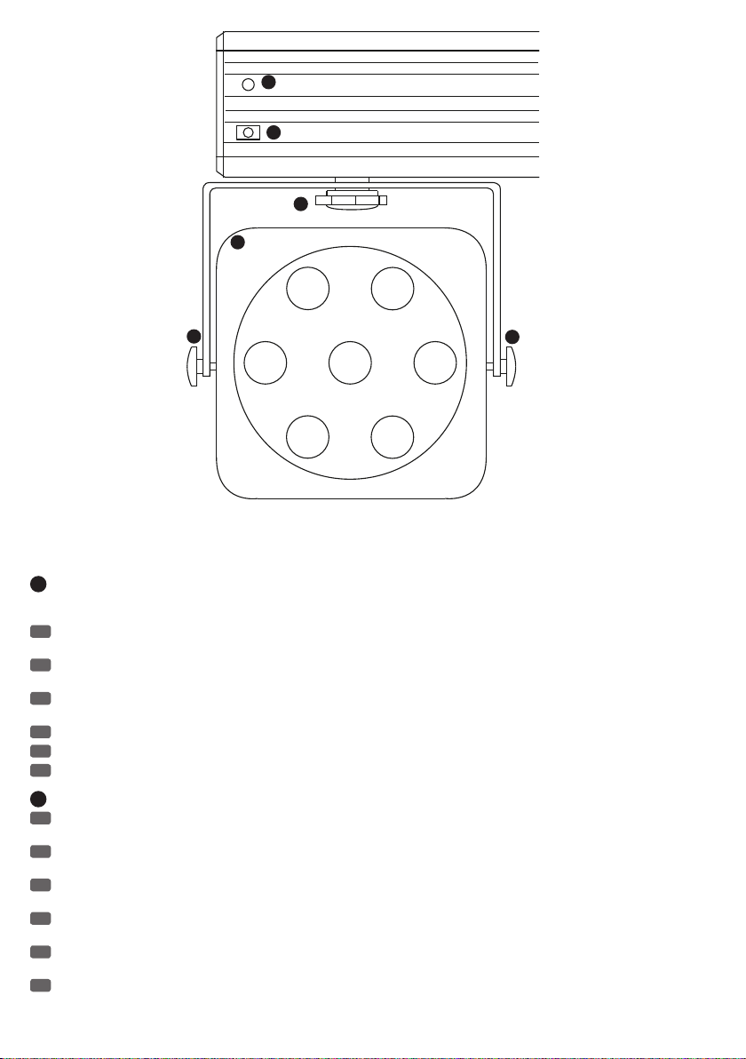
CONTROLS AND DISPLAY / BEDIEN- UND ANZEIGEELEMENTE / CONTRÔLES ET INDICATEURS /
CONTROLES E INDICADORES / ELEMENTY OBSŁUGI I WYŚWIETLACZA / DISPOSITIVI DI COMANDO
E VISUALIZZAZIONE
11
4 5 6
1 2
12
1
NEUTRIK POWERCON POWER INPUT SOCKET / NEUTRIK POWERCON NETZEINGANGSBUCHSE / EMBASE SECTEUR NEUTRIK
POWERCON / ENTRADA ELÉCTRICA POR NEUTRIK POWERCON / GNIAZDO SIECIOWE WEJŚCIOWE NEUTRIK POWERCON / PRESA DI
ENTRATA NEUTRIK POWERCON
EN
Power cord with matching Neutrik PowerCon plug included. Always make certain that the operating voltage of the multi PAR lighting system
(printed on the rear panel) matches the mains voltage in your region.
DE
Netzkabel mit passendem Neutrik powerCON Stecker im Lieferumfang. Vergewissern Sie sich stets, dass die Betriebsspannung der Multipar
Lichtanlage (Aufdruck auf der Rückseite) der in Ihrer Region geltenden Netzspannung entspricht.
FR
Livré avec câble secteur équipé d‘une fiche Neutrik powerCON correspondante. Assurez-vous toujours que la valeur de tension d‘alimentation
du caisson de basses actif (sérigraphiée sur le panneau arrière) correspond à la valeur de tension secteur locale.
ES
Se suministra el cable eléctrico con conectores Neutrik powerCON. Compruebe siempre que la tensión operativa del set de proyectores Multi
PAR (serigrafiada en el panel posterior) coincide con el suministro eléctrico existente.
PL
Kabel sieciowy z kompatybilną wtyczką Neutrik PowerCON w zestawie Zawsze należy się upewnić, czy napięcie robocze aktywnej instalacji
oświetleniowej MultiPar (nadruk na tylnej stronie) odpowiada obowiązującemu w danym obszarze napięciu sieciowemu.
IT
Cavo di alimentazione con corrispondente connettore Neutrik powerCON in dotazione. Verificare sempre che la tensione di esercizio del set
proiettori Multi PAR (stampata sul pannello posteriore) corrisponda alla tensione di rete erogata nella propria area.
8
9
7
3
11
10
10
12
13
Page 14
15
16
A
13
B
2
NEUTRIK POWERCON POWER OUTPUT SOCKET / NEUTRIK POWERCON NETZAUSGANGSBUCHSE / RENVOI SECTEUR NEUTRIK
POWERCON / SALIDA ELÉCTRICA POR NEUTRIK POWERCON / GNIAZDO SIECIOWE WYJŚCIOWE NEUTRIK POWERCON / PRESA DI ENTRATA
NEUTRIK POWERCON
EN
For powering additional CAMEO lighting products. Make certain that the power consumption of the connected devices does not exceed 10
amperes.
DE
Zur Versorgung weiterer CAMEO Lichtprodukte. Achten Sie darauf, dass die Stromaufnahme des angeschlossenen Geräts 10 Ampere nicht
überschreiten darf.
FR
Pour alimentation d‘autres projecteurs CAMEO. Vérifiez bien que l‘intensité consommée par l‘appareil connecté sur cette embase ne dépasse
pas 10 Ampères.
ES
Para alimentar otros equipos de iluminación CAMEO. Asegúrese de que el consumo del equipo conectado no supere los 10amperios.
PL
Do zasilania dodatkowych reflektorów CAMEO. Należy zadbać o to, aby pobór prądu przez podłączone urządzenie nie przekraczał 10 amperów.
IT
Per alimentazione di ulteriori prodotti CAMEO. Ricordare che la potenza assorbita dell'apparecchio collegato non deve superare i 10 Ampere.
3
FUSE HOLDER / SICHERUNGSHALTER / PORTE-FUSIBLE / PORTAFUSIBLES / PODSTAWA BEZPIECZNIKA / PORTAFUSIBILI
EN
IMPORTANT INFORMATION: Replace the fuse only with a fuse of the same type and rating. If the fuse blows repeatedly, please contact an
authorised service centre.
DE
WICHTIGER HINWEIS: Ersetzen Sie die Sicherung ausschließlich durch eine Sicherung des gleichen Typs und mit gleichen Werten. Sollte die
Sicherung wiederholt auslösen, wenden Sie sich bitte an ein autorisiertes Servicezentrum.
FR
CONSEIL IMPORTANT : Remplacez exclusivement le fusible par un fusible neuf du même format et du même calibre (valeurs indiquées sur le
panneau arrière de l‘appareil). Si le fusible fond de façon répétée, veuillez consulter un centre de réparations agréé.
ES
NOTA IMPORTANTE: Sustituya el fusible únicamente por otro del mismo tipo y características. Si el fusible se fundiera continuamente, póngase
en contacto con un servicio técnico autorizado.
PL
WAŻNA INFORMACJA: bezpiecznik należy wymieniać wyłącznie na bezpiecznik tego samego typu i o takich samych parametrach. Jeśli
bezpiecznik stale się przepala, należy skontaktować się z autoryzowanym centrum serwisowym.
IT
NOTA IMPORTANTE Sostituire il fusibile solo con un fusibile dello stesso tipo e con gli stessi valori. Se il fusibile continua a saltare, rivolgersi a
un centro di assistenza autorizzato.
B
14
Page 15

4
DMX INPUT / DMX-EINGANG / ENTRÉE DMX / ENTRADA DMX / WEJŚCIE DMX / INGRESSO DMX
EN
Male, 3-pole XLR socket. Used for connection to a DMX mixer or other DMX controllers. The connection is made using a DMX cable.
DE
Männliche, 3-polige XLR-Buchse. Dient der Verbindung mit einem DMX-Mischpult, oder anderen DMX-Kontrollgeräten. Die Verbindung erfolgt
durch ein DMX-Kabel.
FR
connecteur XLR mâle 3 points Permet de connecter un pupitre DMX, ou tout autre contrôleur DMX. La connexion s‘effectue par l‘intermédiaire
d‘un câble DMX.
ES
XLR macho de 3 pines. Para conectar una mesa de iluminación DMX u otro equipo de control DMX. La conexión se realiza mediante un cable
DMX.
PL
3-stykowe gniazdo XLR, męskie Służy do podłączenia pulpitu mikserskiego lub innych urządzeń sterujących DMX. Połączenie poprzez kabel
DMX.
IT
Presa XLR maschio a 3 poli. Per collegare un mixer DMX o altri apparecchi di controllo DMX. Il collegamento avviene tramite cavo DMX.
5
DMX OUTPUT / DMX-AUSGANG / SORTIE DMX / SALIDA DMX / WYJŚCIE DMX / USCITA DMX
EN
Female, 3-pole XLR socket. Used to loop through the DMX signal to additional DMX devices.
DE
Weibliche, 3-polige XLR-Buchse. Dient der Weiterleitung des DMX-Signals an weitere DMX-Endgeräte.
FR
Connecteur XLR femelle 3 points Permet de renvoyer le signal DMX reçu vers un autre appareil DMX.
ES
XLR hembra de 3 pines. Para enviar la señal DMX a otros equipos DMX.
PL
3-stykowe gniazdo XLR, żeńskie Służy do przesyłania sygnału DMX do kolejnych urządzeń DMX.
IT
Presa XLR femmina a 3 poli. Per inoltrare il segnale DMX ad altri terminali DMX.
6
INPUT FOR FOOT PEDAL/ EINGANG FÜR FUSSPEDAL / ENTRÉE POUR PÉDALIER / ENTRADA PARA PEDALERA / WEJŚCIE DLA PEDAŁU
NOŻNEGO / ENTRATA PER PEDALIERA
EN
Female, 5-pole XLR socket for connecting the optional CLMPARFOOT2 foot pedal. The socket delivers the supply voltage for the foot pedal, so it
must always be connected using a 5-pole DMX cable with all signals connected.
DE
Weibliche, 5-polige XLR-Buchse zum Anschliessen des optionalen Fußpedals CLMPARFOOT2. Die Buchse liefert die Spannungsversorgung für
das Fußpedal, von daher muss stets ein vollbelegtes 5-Pol DMX Kabel zum Anschluss verwendet werden.
FR
Embase XLR femelle 5 points, pour connexion du pédalier optionnel CLMPARFOOT2. Cette embase fournit la tension d‘alimentation du pédalier : il
faut donc toujours utiliser, pour le branchement, un câble DMX dont les 5 points sont connectés.
ES
XLR hembra de 5 pines para conectar la pedalera opcional CLMPARFOOT2. Como el conector permite alimentar la pedalera, utilice siempre un
cable DMX de 5pines, con todos los pines conectados.
PL
5-stykowe, żeńskie gniazdo XLR do podłączania opcjonalnego pedału nożnego CLMPARFOOT2. Gniazdo służy jako źródło napięcia dla pedału
nożnego, dlatego należy zawsze stosować w pełni podłączony 5-stykowy kabel DMX.
IT
Presa XLR femmina a 5 poli per collegare la pedaliera opzionale CLMPARFOOT2. La presa fornisce alimentazione di tensione per la pedaliera,
pertanto per il collegamento si deve sempre impiegare un cavo DMX a 5poli completamente coperto.
7
MICROPHONE FOR MUSIC CONTROL/ MIKROFON FÜR DIE MUSIKSTEUERUNG / MICROPHONE POUR PILOTAGE PAR LA MUSIQUE /
MICRÓFONO PARA EL CONTROL POR SONIDO / MIKROFON DO STEROWANIA MUZYKĄ / MICROFONO PER COMANDO TRAMITE MUSICA
8
USB INTERFACE/ USB-SCHNITTSTELLE / PORT USB / CONECTOR USB / INTERFEJS USB / INTERFACCIA USB
EN
Used for service purposes. Not usable by the user.
DE
Dient Service-Zwecken. Vom Anwender nicht nutzbar.
FR
Pour service uniquement. Non accessible à l‘utilisateur.
ES
Para operaciones de mantenimiento. No disponible para el usuario.
PL
Służy do czynności serwisowych. Nieprzydatny dla użytkownika.
IT
A scopo di assistenza. Non utilizzabile dall'utente.
9
LIGHTED LC DISPLAY WITH 4 CONTROL BUTTONS / BELEUCHTETES LC-DISPLAY MIT 4 BEDIENTASTEN / ÉCRAN LCD RÉTRO-ÉCLAIRÉ,
AVEC 4 TOUCHES / PANTALLA LCD ILUMINADA Y 4 BOTONES DE CONTROL / PODŚWIETLANY EKRAN LCD Z CZTEREMA PRZYCISKAMI
OBSŁUGI / DISPLAY LCD ILLUMINATO CON 4PULSANTI DI COMANDO
EN
See the following pages of the User Manual.
DE
Siehe Bedienanleitung auf den folgenden Seiten.
FR
Voir instructions dans les pages suivantes.
ES
Consulte las instrucciones en las páginas siguientes del manual.
PL
Patrz Instrukcja obsługi na kolejnych stronach.
IT
Vedere il manuale nelle pagine seguenti.
15
Page 16

10
SAFETY PLUG POWER OUTLETS 1 AND 2 / SCHUTZKONTAKTSTECKER NETZBUCHSEN 1 UND 2 / EMBASES SECTEUR FICHE AVEC PRISE
DE TERRE 1 ET 2 / BASES ENCHUFE CON TOMA DE TIERRA 1 Y 2 / GNIAZDA SIECIOWE WTYCZKA Z UZIEMIENIEM 1 I 2 / PRESE SPINA
TEDESCA 1 E 2
EN
Separate power sockets, switchable via DMX, infrared remote control, and optional foot pedal, for powering additional CAMEO lighting products.
Make certain that the power consumption of the connected devices does not exceed 3 amperes.
DE
Über DMX, Infrarot Fernbedienung und optionalem Fußpedal separat schaltbare Netzbuchsen zur Versorgung weiterer CAMEO Lichtprodukte.
Achten Sie darauf, dass die Stromaufnahme des angeschlossenen Geräts 3 Ampere nicht überschreiten darf.
FR
Embases commutables via DMX, télécommande infrarouge et pédalier optionnel, pour alimenter d‘autres projecteurs CAMEO. Attention à ce
que l‘intensité consommée par l‘appareil connecté ne dépasse pas 3 Ampères.
ES
Bases eléctricas conmutables de forma independiente mediante el protocolo DMX, un mando a distancia por infrarrojos o una pedalera
opcional, para alimentar otros equipos de iluminación CAMEO. Asegúrese de que el consumo del equipo conectado no supere los 3amperios.
PL
Gniazda sieciowe włączane niezależnie poprzez DMX, pilota na podczerwień i opcjonalny pedał nożny, służące do zasilania dodatkowych
reflektorów CAMEO. Należy zadbać o to, aby pobór prądu przez podłączone urządzenie nie przekraczał 3 amperów.
IT
Prese attivabili separatamente tramite DMX, telecomando IR e pedaliera opzionale; per alimentazione di ulteriori prodotti CAMEO. Ricordare che
la potenza assorbita dell'apparecchio collegato non deve superare i 3Ampere.
11
MOUNTS 1 AND 2 / HALTERUNG 1 UND 2 / 1 ET 2 / SOPORTES 1 Y 2 / MOCOWANIE 1 I 2 / SUPPORTO 1 E 2
EN
Moveable mount for mounting up to 2 additional lights, for example, the CAMEO CLMOVER1. The weight of the lights to be mounted must not
exceed 5 kg each. IMPORTANT INFORMATION: When mounting one or two additional lights, make certain that the overall construction is not
overweighted on one side (balanced distribution of weight) and that the maximum load of the stand used is not exceeded! For mounting, please use
only the included mounting bolts.
DE
Verschiebbare Halterung für die Montage von bis zu 2 weiterer Lichtstrahler wie z.B. dem CAMEO CLMOVER1. Das Gewicht der zu
montierenden Lichtstrahler darf jeweils 5 kg nicht überschreiten. WICHTIGER HINWEIS: Bei der Montage von einem oder zwei zusätzlichen
Lichtstrahler ist zum einen darauf zu achten, dass die gesamte Konstruktion kein Übergewicht zu einer Seite bekommt (ausgewogene Gewichtsverteilung), zum anderen darf die maximale Traglast des verwendeten Stativs nicht überschritten werden! Bitte verwenden Sie zur Montage
ausschließlich die mitgelieferten Befestigungsschrauben.
FR
Support réglable, pour montage d‘un maximum de 2 projecteurs supplémentaires, comme par exemple le CAMEO CLMOVER1. Le poids total
des projecteurs ainsi montés ne doit pas dépasser 5 kg. CONSEIL IMPORTANT : Lors du montage d‘un ou deux projecteurs supplémentaires,
attention à ce que l‘assemblage final ne soit pas déséquilibré au niveau de la répartition des masses (surcharge d‘un côté), et à ce que la charge
maximale du pied utilisé ne soit pas dépassée ! N‘utilisez, pour le montage, que les vis de fixation fournies.
ES
Soporte deslizante para el montaje de hasta 2 focos adicionales, p. e., el CLMOVER1 de CAMEO. El peso cada foco no debe superar los 5kg.
NOTA IMPORTANTE: Al montar uno o dos focos adicionales, asegúrese de repartir el peso de manera uniforme (el conjunto quedaría desequilibrado) y
de no superar la capacidad de carga máxima del soporte. Utilice únicamente los tornillos de montaje suministrados.
PL
Regulowane mocowanie do montażu maks. 2 dodatkowych reflektorów, np. CAMEO CLMOVER1. Waga każdego z montowanych reflektorów nie
może przekraczać 5 kg. WAŻNA INFORMACJA: w przypadku montażu jednego lub dwóch dodatkowych reflektorów należy pamiętać o tym, aby
konstrukcja miała taką samą wagę po obu stronach (równomierne rozłożenie obciążenia), a także aby nie została przekroczona maksymalna nośność
stosowanego statywu. Do montażu należy stosować wyłącznie dostarczone wraz z produktem śruby mocujące.
IT
Supporto scorrevole per il montaggio di max. 2altri proiettori luminosi come CAMEO CLMOVER1. Il peso del proiettore luminoso da montare
non può superare i 5kg. NOTA IMPORTANTE In caso di montaggio di uno o due ulteriori proiettori luminosi, ricordare che la struttura non acquisisce
sovrappeso (distribuzione squilibrata del peso) e che non si deve superare la portata massima dello stativo impiegato. Per il montaggio, impiegare
solo le viti di fissaggio incluse nella fornitura.
12
POWER CORD FOR LIGHTS 1 – 4 / VERSORGUNGSKABEL FÜR STRAHLER 1 BIS 4 / CÂBLE D’ALIMENTATION POUR LES PROJECTEURS
1 À 4 / CABLES DE ALIMENTACIÓN ELÉCTRICA DE LOS FOCOS 1 A 4 / KABLE ZASILAJĄCE DLA REFLEKTORÓW 1 DO 4 / CAVO DI
ALIMENTAZIONE PER PROIETTORI DA 1 A 4
13
ADJUSTING SCREWS / VERSTELLSCHRAUBEN / VIS DE RÉGLAGE / TORNILLOS DE AJUSTE / ŚRUBY REGULACYJNE / VITI DI
REGOLAZIONE
EN
Using the adjusting screws A and B, each of the 4 lights can be adjusted separately both horizontally and vertically.
DE
Mit Hilfe der Verstellschrauben A und B kann jeder der 4 Strahler separat sowohl horizontal als auch vertikal verstellt werden.
FR
À l‘aide des vis de réglage A et B, vous pouvez régler séparément chacun des 4 projecteurs, tant dans le plan horizontal que dans le plan
vertical.
ES
Los tornillos de ajuste A y B permiten ajustar la posición horizontal y vertical de cada uno de los 4 focos de forma independiente.
PL
Za pomocą śrub regulacyjnych A i B można zmienić pozycję każdego z 4 reflektorów oddzielnie, zarówno w płaszczyźnie poziomej, jak i
pionowej.
IT
Con le viti A e B, è possibile spostare ognuno dei 4 proiettori separatamente, sia in orizzontale che in verticale.
14
INFRARED INTERFACE / INFRAROT-SCHNITTSTELLE / PORT INFRAROUGE / RECEPTOR DE INFRARROJOS / INTERFEJS PODCZERWIENI /
INTERFACCIA A INFRAROSSI
EN
In „IR ACTIVE“ mode, this interface on the front of the multi PAR lighting system is used to control the unit with the included infrared remote
control. Make certain that there is a direct line of sight between the infrared interface of the remote control and the infrared interface of the multi
PAR lighting system.
16
Page 17

DE
In der Betriebsart „IR ACTIVE“ dient diese, auf der Vorderseite der Multipar Lichtanlage befindlichen Schnittstelle, der Steuerung durch die
mitgelieferte Infrarot-Fernbedienung. Achten Sie darauf, die Infrarot-Schnittstelle der Fernbedienung in direktem Sichtkontakt zu der Infrarot-Schnittstelle der Multipar Lichtanlage zu positionieren.
FR
En mode „IR ACTIVE“, ce port situé en face avant du projecteur Multi-PAR autorise le pilotage de ses fonctions par l‘intermédiaire de la
télécommande infrarouge. Veillez à ce que la télécommande se trouve en contact visuel direct avec le port infrarouge du projecteur Multi-PAR.
ES
Situado en el frontal del set de proyectores Multi PAR, al activar el modo „IR ACTIVE“ permite controlar el equipo con el mando a distancia
suministrado. Asegúrese de que el mando a distancia por infrarrojos tiene visión directa con el receptor de infrarrojos del set de proyectores Multi
PAR.
PL
W trybie pracy „IR ACTIVE” ten interfejs, znajdujący się na przedniej stronie instalacji oświetleniowej MultiPar, służy do sterowania za pomocą
dostarczonego w zestawie pilota na podczerwień. Należy pamiętać, aby ustawić interfejs podczerwieni pilota w bezpośrednim „kontakcie
wzrokowym” z interfejsem podczerwieni instalacji oświetleniowej MultiPar.
IT
In modalità IR ACTIVE, quest'interfaccia ubicata sul pannello frontale del set Multi PAR serve per controllare tramite il telecomando IR.
Ricordare che l'interfaccia a infrarossi del telecomando deve essere posizionato a contatto diretto di visibilità con l'interfaccia a infrarossi del set
Multi PAR.
15
INDICATOR LED / ANZEIGE-LED / INDICATEURS LED / INDICADOR LED / SYGNALIZACYJNA DIODA LED / LED INDICATORI
EN
As soon as a control command is given via the IR remote control, the indicator LED flashes.
DE
Sobald ein Steuerbefehl durch die IR Fernbedienung erfolgt, leuchtet die Anzeige-LED kurz auf.
FR
Dès qu‘un signal de commande est transmis par la télécommande infrarouge, la LED s‘allume brièvement.
ES
Cuando se envía una orden mediante mando a distancia por infrarrojos, el LED se ilumina brevemente.
PL
Po wysłaniu przez pilota na podczerwień sygnału sterującego dioda LED emituje krótki sygnał świetlny.
IT
Non appena si verifica un errore di comando tramite il telecomando IR, il LED si accende brevemente.
OPERATION / BEDIENUNG / UTILISATION / OPERACIÓN / OBSŁUGA / UTILIZZO
EN
MUSIC CONTROL
Press the MODE button repeatedly until “SOUND MODE” appears in the display. Now the lighting system is controlled by the built-in microphone
and follows the beat of the music. Press the ENTER button. The cursor appears in the “SENS:xx” field in the bottom line of the display. Now you can
use the UP and DOWN buttons to adjust the microphone sensitivity (00 - 31), whereby “00” means minimum sensitivity and “31” means maximum
sensitivity, then confirm with ENTER. Simultaneously, the cursor jumps to the “P:xx” field. Here, you can now use the UP and DOWN buttons to select
one of 15 lighting programs in music control mode. Confirm the input with ENTER.
INTERNAL PROGRAMS
Press the MODE button repeatedly until one of the 18 internal programs appears in the display:
01.STATIC
(static colours)
02.DREAM
(15 different colour with crossfades between one another. The effect speed is separately adjustable and a stroboscope effect can be activated
additionally)
03.METEOR
(The four lights are activated and deactivated one after the other in specific sequences with varying colour and intensity. The effect speed is separately adjustable and a stroboscope effect can be activated additionally)
04.FADE
(15 different colours that are faded in and out one after the other. The effect speed is separately adjustable and a stroboscope effect can be activated
additionally)
05.CHANGE
(15 different alternating colours. The effect speed is separately adjustable and a stroboscope effect can be activated additionally)
17
Page 18

06.-18.FLOW1-13
(All FLOW programs consist of various programmed colour change effects. The effect speed is separately adjustable and a stroboscope effect can be
activated additionally)
Pressing the ENTER button makes the cursor appear in the top line of the display. Now the desired program can be selected using the UP and DOWN
buttons. Confirm the input with ENTER.
To change the colour in STATIC program 01, press ENTER repeatedly until the cursor appears in the “CL:xxxx” field in the bottom line. Now “blackout” (BLAC = all LEDs off) or a colour mixture can be selected using the UP and DOWN buttons. “RGBW” means that all LEDs (red, green, blue, and
white) operate at full power, resulting in a bright white colour. Primary colours (R = red, G = green, B = blue, and W = white) and colour mixtures
such as “RG” (red and green = yellow) and “RB” (red and blue = magenta), etc., can be selected here. Confirm the input with ENTER.
The cursor jumps to the “Flashxx” field. Here you can now add a stroboscope effect to the selected colour. “Flash00” stands for stroboscope effect
deactivated, “Flash01” for the slowest and “Flash99” for the fastest flash frequency. Once the desired stroboscope effect has been set, press ENTER
to confirm the input.
The effect speed and stroboscope frequency can each be adjusted separately for programs 02 – 18. Press ENTER repeatedly until the cursor appears
in the top line of the display and then use the UP and DOWN buttons to select the desired program 02 – 18. Press ENTER again to confirm the
change and move the cursor to the field “Speedxx” in the bottom line. Now the effect speed can be set using the UP and DOWN buttons. “00” stands
for the slowest and “99” for the fastest speed.
Pressing the ENTER button again confirms the input and moves the cursor to the “Flashxx” field. Now the stroboscope effect can be set as desired
using the UP and DOWN buttons. “Flash00” stands for stroboscope effect deactivated, “Flash01” for the slowest and “Flash99” for the fastest flash
frequency. Once the desired stroboscope effect has been set, press ENTER to confirm the input.
AUTO RUN
In AUTO RUN mode, various colour change, colour fade, and meteor programmes run in succession.
Press the MODE button repeatedly until “AUTO RUN” appears in the display. To set the sequential speed of the individual programs, press ENTER. The
cursor appears in the “FQN:xx” field in the bottom line. Use the UP and DOWN buttons to set the speed at which the individual programmes follow
one another to the desired value. “FQN:01” stands for the fastest sequence, “FQN:99” for the fastest sequence of the programs. Press ENTER to
confirm the input.
FLOW INVERT
The direction of flow of lighting sequences, for example, in the METEOR programme, can be inverted using the “FLOW INVERT” function.
Press the MODE button repeatedly until “FLOW INVERT” appears in the display. Now press ENTER. The cursor appears in the bottom line of the
display. Use the UP and DOWN buttons to select whether the flow direction should be inverted (ON) or not (OFF). To confirm the input, press ENTER.
DIMMER CURVE
The operating modes “DIMMER CURVE LED” and “DIMMER CURVE HALOGEN” can be used to determine how the light reacts to sudden, large jumps
in DMX dimmer values in DMX mode (DMX value 000 directly to 255 and the other way round). In “LED” mode, the lights react to the change in
value immediately without delay and in “HALOGEN” mode they react in a manner similar to that of a halogen lamp with a slight delay (pre-glow and
afterglow). Press the MODE button repeatedly until “DIMMER CURVE” appears in the display. As soon as you press ENTER, the cursor appears in the
bottom line of the display. Now the desired mode can be selected using the UP and DOWN buttons. Confirm the input with ENTER.
18
Page 19

IR ACTIVE
In “IR ACTIVE” mode, the multi-PAR lighting system can be controlled solely via the included infrared remote control. To control the lighting system
in this mode, press the MODE button repeatedly until “IR ACTIVE” appears in the display. Then press ENTER. The cursor appears in the bottom line of
the display. Use the UP and DOWN buttons to select “ON”. Confirm the input with ENTER.
If you later want to control the system in DMX mode, by foot pedal or in a stand-alone mode, set the “IR ACTIVE” mode to “OFF” again in the same
manner.
MASTER DIMMER
The “MASTER DIMMER” lets you set the basic brightness of the lighting system in the stand-alone modes and when controlling it by foot pedal. Press
the MODE button repeatedly until “MASTER DIMMER” appears in the display. Then press ENTER. The cursor appears in the bottom line of the display.
Use the UP and DOWN buttons to set the desired basic brightness (00 - 99) and confirm the input with ENTER.
DIMMER
In “DIMMER” mode, each of the four individual lights can be set to an individual static colour through colour mixing. Press the MODE button repeatedly until “DIMMER” appears in the display. Then press ENTER and use the UP and DOWN buttons to select the desired light 1 - 4 and confirm with
ENTER. Now the display shows the brightness values of the individual colour LEDS (R = red, G = green, B = blue, and W = white) of the selected light
from 00 to 99. The cursor is the “R” field in the top line. Now use the UP and DOWN buttons to set the brightness of the red LED. Pressing ENTER
confirms the input and moves the cursor ahead to the “G” field for the green colour LEDs. Here, again use the UP and DOWN buttons to set the
brightness to the desired value. The same procedure also applies analogously for the blue (b) and white (w) LEDs.
After confirming the value for the white LEDs by pressing ENTER, “DIMMER” appears in the display again and you can select one of the four lights for
colour adjustment as described above.
DMX MODE
This menu item makes it possible to select both the DMX start address and the DMX mode in which the multi-PAR lighting system should operate.
Press the MODE button repeatedly until “DMX MODE” appears in the display. Then press ENTER. The cursor appears in the “ADDR:xxx” field. Use the
UP and DOWN buttons to select the DMX start address of the lighting system from 001 to 512. Confirm the input with ENTER. Simultaneously, the
cursor jumps ahead to the “CH:xx” field. There are 7 different DMX modes that can be selected using the UP and DOWN buttons. Confirm the input
with ENTER. The various DMX modes are explained on one of the following pages.
SLAVE MODE
If you want to control the LED multi-PAR lighting system either using the optional foot switch (CLMPARFOOT2) or have it controlled by a second
CLMPAR3 (master) in one of the stand-alone modes, the “SLAVE MODE” must be selected. Press the MODE button repeatedly until “SLAVE MODE”
appears in the display. The connection between the master and slave unit is made using a DMX cable, whereby the DMX output of the master unit
must be connected to the DMX input of the slave unit.
Note: The illumination of the LC display switches off automatically after approx. 1 minute of inactivity. Pressing any one of the 4 control buttons will
turn on the illumination of the LC display again.
19
Page 20

DE
MUSIKSTEUERUNG
Drücken Sie die MODE-Taste so oft, bis im Display “SOUND MODE” erscheint. Nun wird die Lichtanlage über das eingebaute Mikrofon gesteuert und
folgt dem Takt der Musik. Drücken Sie die ENTER-Taste. Der Cursor erscheint im Feld “SENS:xx” in der unteren Zeile des Displays. Nun können Sie
mit den Tasten UP und DOWN die Empfindlichkeit des Mikrofons (00 - 31) einstellen, wobei “00” die geringste Empfindlichkeit und “31” die höchste
Empfindlichkeit bedeuten, dann bestätigen Sie mit ENTER. Gleichzeitig springt der Cursor in das Feld “P:xx”. Hier können Sie jetzt mit Hilfe der UP
und DOWN Tasten eines von 15 Lichtprogrammen im Musiksteuerungsmodus auswählen. Bestätigen Sie die Eingabe mit ENTER.
INTERNE PROGRAMME
Drücken Sie die MODE-Taste so oft, bis im Display eines der 18 internen Programme erscheint:
01.STATIC
(statische Farben)
02.DREAM
(15 verschiedene Farben, die ineinander übergeblendet werden. Die Laufgeschwindigkeit des Effekts ist separat einstell- und ein Stroboskopeffekt
zusätzlich aktivierbar)
03.METEOR
(Die 4 Strahler werden in bestimmten Sequenzen in unterschiedlicher Farbe und Intensität nacheinander aktiviert und deaktiviert. Die Laufgeschwindigkeit des Effekts ist separat einstell- und ein Stroboskopeffekt zusätzlich aktivierbar)
04.FADE
(15 verschiedene Farben, die nacheinander ein- und ausgeblendet werden. Die Laufgeschwindigkeit des Effekts ist separat einstell- und ein Stroboskopeffekt zusätzlich aktivierbar)
05.CHANGE
(15 Verschiedene Farben wechseln einander ab. Die Laufgeschwindigkeit des Effekts ist separat einstell- und ein Stroboskopeffekt zusätzlich
aktivierbar)
06.-18.FLOW1-13
(Alle FLOW Programme bestehen aus verschieden programmierten Farbwechseleffekten. Die Laufgeschwindigkeit des Effekts ist separat einstellund ein Stroboskopeffekt zusätzlich aktivierbar)
Durch Drücken der ENTER Taste erscheint der Cursor in der oberen Zeile des Displays. Nun kann mit Hilfe der UP und DOWN Tasten das gewünschte
Programm ausgewählt werden. Bestätigen Sie die Eingabe mit ENTER.
Um die Farbe im STATIC Programm 01 zu ändern, drücken Sie ENTER so oft, bis der Cursor im Feld „CL:xxxx“ in der unteren Zeile erscheint. Nun
kann mit Hilfe der UP und DOWN Tasten „Blackout“ (BLAC = alle LEDs aus), oder eine Farbmischung ausgewählt werden. „RGBW“ heißt, alle LEDs
(Rot, Grün, Blau und Weiß) werden auf voller Leistung betrieben, wobei diese Farbmischung in einem hellen Weißton resultiert. Grundfarben (R =
Rot, G = Grün, B = Blau und W = Weiß) und Farbmischungen wie „RG“ (Rot und Grün = Gelb) und „RB“ (Rot und Blau = Magenta) usw. können hier
ausgewählt werden. Bestätigen Sie die Eingabe mit ENTER. Der Cursor springt in das Feld „Flashxx“. Hier kann nun der eingestellten Farbe ein Stroboskopeffekt hinzugefügt werden. „Flash00“ steht für Stroboskopeffekt deaktiviert, „Flash01“ für die langsamste und „Flash99“ für die schnellste
Blitzfrequenz. Sobald der gewünschte Stroboskopeffekt eingestellt ist, drücken Sie auf ENTER um die Eingabe zu bestätigen.
20
Page 21

Die Programme 02 bis 18 können in Laufgeschwindigkeit und Stroboskopfrequenz jeweils separat eingestellt werden. Drücken Sie ENTER so oft, bis
der Cursor in der oberen Zeile des Displays erscheint und wählen Sie das gewünschte Programm 02 bis 18 mit Hilfe der UP und DOWN Tasten aus.
Drücken Sie erneut ENTER um den Vorgang zu bestätigen und den Cursor in die untere Zeile zum Feld „Speedxx“ zu bewegen. Mit Hilfe der UP und
DOWN Tasten kann nun die Laufgeschwindigkeit des Effekts eingestellt werden. „00“ steht für die langsamste, „99“ für die schnellste Geschwindigkeit.
Nochmaliges Drücken der ENTER Taste bestätigt die Eingabe und bringt den Cursor zum Feld „Flashxx“. Nun kann der Stroboskopeffekt mit Hilfe
der UP und DOWN Tasten wunschgemäß eingestellt werden. „Flash00“ steht für Stroboskopeffekt deaktiviert, „Flash01“ für die langsamste und
„Flash99“ für die schnellste Blitzfrequenz. Sobald der gewünschte Stroboskopeffekt eingestellt ist, drücken Sie auf ENTER um die Eingabe zu
bestätigen.
AUTO RUN
In der AUTO RUN Betriebsart laufen verschiedene Farbwechsel-, Überblend- und Meteorprogramme hintereinander ab.
Drücken Sie die MODE Taste so oft, bis im Display „AUTO RUN“ erscheint. Um die Abfolgegeschwindigkeit der einzelnen Programme einzustellen,
drücken Sie auf ENTER. Der Cursor erscheint in der unteren Zeile im Feld „FQN:xx“. Setzen Sie mit Hilfe der UP und DOWN Tasten die Geschwindigkeit, mit der die einzelnen Programme abfolgen, auf den gewünschten Wert. „FQN:01“ steht für die schnellste Abfolge, „FQN:99“ für die langsamste
Abfolge der Programme. Drücken Sie ENTER um die Eingabe zu bestätigen.
FLOW INVERT
Die Laufrichtung von Lichtsequenzen, beispielsweise die des METEOR Programmes, kann mit Hilfe der „FLOW INVERT“ Funktion umgekehrt werden.
Drücken Sie die MODE Taste so oft, bis im Display „FLOW INVERT“ erscheint. Drücken Sie nun auf ENTER, der Cursor erscheint in der unteren Zeile
des Displays, und wählen mit Hilfe der UP und DOWN Tasten aus, ob die Laufrichtung invertiert werden soll (ON), oder nicht (OFF). Um die Eingabe zu
bestätigen, drücken Sie ENTER.
DIMMER CURVE
Mit Hilfe der beiden Betriebsarten „DIMMER CURVE LED“ und „DIMMER CURVE HALOGEN“ kann eingestellt werden, wie die Strahler im DMX-Betrieb auf plötzliche, große DMX-Dimmerwert-Sprünge reagieren (DMX-Wert 000 direkt auf 255 und umgekehrt). In der Betriebsart „LED“ reagieren
die Strahler sofort, ohne Verzögerung auf die Werteänderung und in der Betriebsart „HALOGEN“ ähnlich wie eine Halogenlampe etwas verzögert
(Einglühen und Nachglühen). Drücken Sie die MODE Taste so oft, bis im Display „DIMMER CURVE“ angezeigt wird. Sobald Sie auf ENTER drücken,
erscheint der Cursor in der unteren Zeile des Displays. Mit Hilfe der UP und DOWN Tasten kann nun die gewünschte Betriebsart ausgewählt werden.
Bestätigen Sie die Eingabe mit ENTER.
IR ACTIVE
In der „IR ACTIVE“ Betriebsart kann die Multi Par Lichtanlage ausschliesslich über die mitgelieferte Infrarot Fernbedienung gesteuert werden. Um die
Lichtanlage in dieser Betriebsart zu kontrollieren, drücken Sie die MODE Taste so oft, bis im Display „IR ACTIVE“ angezeigt wird. Dann drücken Sie
ENTER, der Cursor erscheint in der unteren Zeile des Displays, und wählen mit Hilfe der UP und DOWN Tasten „ON“ aus. Bestätigen Sie die Eingabe
mit ENTER. Möchten Sie zu einem späteren Zeitpunkt die Anlage in der DMX Betriebsart, per Fußpedal, oder in einer Standalone Betriebsart steuern,
so stellen Sie in gleicher Weise die „IR ACTIVE“ Betriebsart wieder auf „OFF“.
21
Page 22

MASTER DIMMER
Mit Hilfe der „MASTER DIMMER“ Funktion haben Sie die Möglichkeit die Grundhelligkeit der Lichtanlage in den Standalone Betriebsarten und der
Steuerung per Fußpedal einzustellen. Drücken Sie die MODE Taste so oft, bis im Display „MASTER DIMMER“ angezeigt wird. Dann drücken Sie
ENTER, der Cursor erscheint in der unteren Zeile des Displays, stellen mit Hilfe der UP und DOWN Tasten die gewünschte Grundhelligkeit ein (00 -
99) und bestätigen die Eingabe mit ENTER.
DIMMER
In der Betriebsart „DIMMER“ kann jeder der vier einzelnen Strahler durch Farbmischung auf eine individuelle, statische Farbe eingestellt werden.
Drücken Sie die MODE Taste so oft, bis das Display „DIMMER“ anzeigt. Dann drücken Sie ENTER und wählen mit Hilfe der UP und DOWN Tasten den
gewünschten Strahler 1 - 4 aus und bestätigen mit ENTER. Das Display zeigt nun die Helligkeitswerte der einzelnen Farb-LEDs (R = Rot, G = Grün,
B = Blau und W = Weiß) des ausgewählten Strahlers von 00 bis 99 an. Der Cursor befindet sich im Feld „R“ in der oberen Zeile. Mit Hilfe der UP und
DOWN Tasten bestimmen Sie jetzt den Helligkeitswert der roten LEDs. Durch Drücken von ENTER bestätigen Sie die Eingabe zum einen, zum anderen springt der Cursor weiter in das Feld „G“ für die grünen Farb-LEDs. Auch hier verwenden Sie wieder die UP und DOWN Tasten zum Einstellen der
Helligkeit auf den gewünschten Wert. Die gleiche Vorgehensweise trifft auch für die blauen (B) und weißen (W) LEDs zu.
Nach Bestätigung des Wertes für die weißen LEDs durch Drücken von ENTER erscheint im Display wieder „DIMMER“ und Sie können wie oben
beschrieben einen der vier Strahler zur Farbgestaltung auswählen.
DMX MODE
In diesem Menüpunkt können sowohl die DMX-Startadresse eingestellt werden, als auch in welcher DMX-Betriebsart die Multipar Lichtanlage
arbeiten soll. Drücken Sie die MODE Taste so oft, bis im Display „DMX MODE“ angezeigt wird. Dann drücken Sie ENTER, der Cursor erscheint im Feld
„ADDR:xxx“ und wählen die DMX-Startadresse der Lichtanlage mit Hilfe der UP und DOWN Tasten von 001 bis 512 aus. Bestätigen Sie die Eingabe
mit ENTER. Gleichzeitig springt der Cursor weiter in das Feld „CH:xx“. Es stehen Ihnen 7 verschiedene DMX-Betriebsarten zur Verfügung, die mit Hilfe
der UP und DOWN Tasten angewählt werden können. Bestätigen Sie die Eingabe mit ENTER. Die verschiedenen DMX-Betriebsarten werden auf einer
der folgenden Seiten erläutert.
SLAVE MODE
Wenn Sie die LED Multipar Lichtanlage entweder mit Hilfe des optionalen Fußschalters (CLMPARFOOT2), oder von einer zweiten CLMPAR3 (Master)
in einem der Standalone-Betriebsarten steuern wollen, muss die Betriebsart „SLAVE MODE“ ausgewählt sein. Drücken Sie die MODE Taste so oft, bis
im Display „SLAVE MODE“ angezeigt wird. Die Verbindung zwischen Master- und Slave-Einheit erfolgt über ein DMX-Kabel, wobei der DMX-Output
der Master-Einheit mit dem DMX-Input der Slave-Einheit verbunden werden muss.
Hinweis: Die Beleuchtung des LC-Displays schaltet sich nach circa 1 Minute Inaktivität automatisch ab. Durch Betätigen einer der 4 Bedientasten
wird die Beleuchtung des LC-Displays wieder eingeschaltet.
FR
PILOTAGE PAR LA MUSIQUE
Appuyez plusieurs fois sur la touche MODE, jusqu’à ce que la mention “SOUND MODE” apparaisse à l’écran. Dès lors, le projecteur est piloté par le
signal du microphone intégré : il suit donc le tempo de la musique. Appuyez sur la touche ENTER. Le curseur passe alors dans le champ “SENS:xx”,
dans la ligne du bas de l’écran. Vous pouvez à présent régler, avec les touches Haut/Bas, la sensibilité du microphone intégré (de 00 à 31). “00”
correspond à la sensibilité la plus faible, “31” à la sensibilité la plus élevée. Validez ensuite avec la touche ENTER. Le curseur passe alors dans le
champ “P:xx”. Vous pouvez alors, avec les touches Haut/Bas, choisir l’un des 15 programmes de mode de pilotage musical des sources lumineuses.
Validez votre choix en appuyant sur la touche ENTER.
22
Page 23

PROGRAMMES INTERNES
Appuyez sur la touche MODE jusqu‘à ce qu‘un des 18 programmes internes apparaisse à l‘écran.
01.STATIC
(couleurs statiques)
02.DREAM
(15 couleurs différentes, avec mélange progressif. La rapidité de l’effet se règle séparément, et un effet stroboscopique est activable en plus)
03.METEOR
(Les 4 projecteurs sont activés/désactivés selon une certaine séquence, avec des couleurs et des intensités différentes. La rapidité de l’effet se règle
séparément, et un effet stroboscopique est activable en plus)
04.FADE
(15 couleurs différentes, fondu d’entrée et de sortie) La rapidité de l’effet se règle séparément, et un effet stroboscopique est activable en plus)
05.CHANGE
(15 couleurs différentes se succèdent. La rapidité de l’effet se règle séparément, et un effet stroboscopique est activable en plus)
06.-18.FLOW1-13
(Tous les programmes FLOW se composent d’effets de couleurs programmés différemment. La rapidité de l’effet se règle séparément, et un effet
stroboscopique est activable en complément.)
Appuyez sur ENTER : le curseur repasse alors dans la ligne du haut de l’écran. Vous pouvez alors choisir le programme désiré, avec les touches
Haut/Bas. Validez votre choix en appuyant sur la touche ENTER.
Pour changer la couleur dans le programme STATIC 01, appuyez plusieurs fois sur ENTER, jusqu’à ce que le curseur se retrouve dans le champ
“CL:xxxx” dans la ligne du bas. Vous pouvez à présent choisir, avec les touches Haut/Bas, la fonction “Blackout (BLAC, toutes les LED éteintes) ou
un mélange de couleurs. “RGBW” signifie que toutes les LED (rouges, vertes, bleues et blanches) brilleront à luminosité maximale : ce mélange de
couleurs donne donc un blanc. Vous pouvez aussi choisir les couleurs primaires (R = rouge, G = vert, B = bleu et W = blanc), ou des mélanges de
couleur comme “RG” (rouge + vert = jaune) et “RB” (rouge + bleu = magenta), etc. Validez votre choix en appuyant sur la touche ENTER.
Le curseur passe alors dans le champ “Flashxx”. Vous pouvez ici affecter un effet stroboscopique à la couleur que vous venez de régler. “Flash 00”
correspond à la désactivation de l’effet stroboscopique, “Flash01” à la fréquence d’éclairs la plus lente et “Flash99” à la fréquence d’éclairs la plus
rapide. Une fois que vous avez réglé la fréquence d’effet stroboscopique désirée, appuyez sur ENTER pour valider la valeur.
Les programmes 02 à 18 sont réglables séparément au niveau de la rapidité de succession que de la fréquence de stroboscope. Appuyez plusieurs
fois sur ENTER, jusqu’à ce que le curseur se trouve dans la ligne du haut de l’affichage, puis choisissez le numéro du programme désiré, 02 à
18, avec les touches Haut/Bas. Appuyez de nouveau sur ENTER pour valider ce choix et placer le curseur dans la ligne inférieure, sur le champ
“Speedxx”. Avec les touches Haut/Bas, vous pouvez alors régler la rapidité de l’effet. “00” correspond à la vitesse la plus lente, “99” à la plus rapide.
Appuyez de nouveau sur la touche ENTER pour valider l’entrée et placer le curseur sur le champ “Flashxx”. Vous pouvez alors régler la fréquence des
éclairs du stroboscope à votre guise, via les touches Haut/Bas. “Flash00” correspond à la désactivation du stroboscope, “Flash01” à la fréquence
d’éclair la plus basse, “Flash99” à la fréquence d’éclair la plus rapide. Dès que la fréquence d’éclair est correctement réglée, appuyez sur ENTER
pour valider la valeur.
23
Page 24

AUTO RUN
Dans le mode AUTO RUN, plusieurs effets se succèdent : changeur de couleur, mélangeur de couleur, programme Meteor.
Appuyez sur la touche MODE, jusqu’à ce que la mention “AUTO RUN” apparaisse dans l’afficheur. Pour régler la rapidité de succession des programmes séparés, appuyez sur ENTER. Le curseur passe alors dans la ligne inférieure, dans le champ “FQN:xx”. Réglez avec les touches Haut/Bas la
rapidité de succession des programmes séparés sur la valeur désirée. “FQN01” correspond à la succession la plus rapide; “FQN99” à la succession
la plus lente des programmes.. Appuyez sur ENTER pour valider la valeur.
FLOW INVERT
Le sens des séquences lumineuses, par exemple dans le programme METEOR, peut être inversée, via la touche “FLOW INVERT”.
Appuyez sur la touche MODE, jusqu’à ce que la mention “FLOW INVERT” apparaisse dans l’afficheur. Appuyez alors sur ENTER ; le curseur passe
dans la ligne inférieure de l’afficheur. Choisissez alors, via les touches Haut/Bas, si le sens de parcours de la séquence est inversé (ON) ou non (OFF).
Pour valider ce choix, appuyez sur ENTER.
DIMMER CURVE
Les modes “DIMMER CURVE LED” et “DIMMER CURVE HALOGEN” définissent la réaction du projecteur lorsqu’il reçoit, en mode DMX, des valeurs
variant brutalement (par exemple, de 000 à 255, ou l’inverse. En mode “LED”, le projecteur réagit immédiatement, sans inertie ; en mode “HALOGEN”, il réagit comme une lampe halogène (avec une certaine inertie à l’allumage et à l’extinction).
Appuyez plusieurs fois de suite sur la touche MODE, jusqu’à ce que la mention “DIMMER CURVE” apparaisse dans l’affichage. Dès que vous appuyez
sur ENTER, le curseur passe dans la ligne inférieure. Avec les touches Haut/Bas, choisissez le mode de fonctionnement désiré. Validez vos choix en
appuyant sur la touche ENTER.
IR ACTIVE
Dans le mode de fonctionnement “IR ACTIVE”, le projecteur Multi PAR se contrôle exclusivement via la télécommande infrarouge livrée. Pour activer
ce mode de contrôle, appuyez sur la touche MODE, jusqu’à ce que la mention “IR ACTIVE” apparaisse dans l’afficheur. Appuyez alors sur ENTER : le
curseur passe dans la ligne inférieure de l’affichage, et choisissez “ON” avec les touches Haut/Bas. Validez votre choix en appuyant sur la touche
ENTER. Si par la suite vous désirez revenir à un contrôle du projecteur en mode DMX, par pédalier ou l’utiliser en mode autonome, réglez, selon la
même procédure, le mode “IR ACTIVE’ sur “OFF”.
MASTER DIMMER
La fonction “MASTER DIMMER” permet de régler la luminosité de base du projecteur en mode autonome ou en pilotage par le pédalier. Appuyez
plusieurs fois de suite sur la touche MODE, jusqu’à ce que la mention “MASTER DIMMER” apparaisse dans l’afficheur. Appuyez alors sur ENTER : le
curseur passe dans la ligne inférieure de l’affichage, et choisissez la valeur de luminosité de base (de 00 à 99) avec les touches Haut/Bas.
DIMMER
Le mode de fonctionnement “DIMMER” permet de régler chacun des projecteurs séparés, via mélange de couleurs, sur sa propre couleur fixe.
Appuyez plusieurs fois sur la touche MODE, jusqu’à ce que la mention “DIMMER” apparaisse dans l’afficheur. Appuyez alors sur ENTER puis choisissez, avec les touches Haut/Bas, le numéro du projecteur désiré, de 1 à 4. Validez avec ENTER. L’afficheur indique alors la valeur de luminosité des
différentes couleurs de LED (R = rouge, G = vert, B = bleu, W = blanc) sur le projecteur sélectionné, de 00 à 99. Le curseur se trouve dans le champ
“R” dans la ligne du haut. Vous pouvez alors régler la valeur de luminosité des LED rouges, via les touches Haut/Bas. Appuyer sur ENTER valide la
valeur de cette couleur ; un nouvel appui place le curseur sur le champ “G”, correspondant aux LED vertes. De la même façon, réglez la valeur de
luminosité désirée via les touches Haut/Bas. Procédez ensuite de même pour les LED bleues (B) et blanches (W).
Après validation de la valeur de luminosité pour les LED blanches via la touche ENTER, l’afficheur se retrouve en mode “DIMMER” ; vous pouvez
reprendre la procédure de réglage pour un autre des quatre projecteurs du Multi-PAR.
24
Page 25

DMX MODE
Cet élément de menu permet de définir l’adresse DMX de départ, et dans quel mode DMX le projecteur Multi-PAR doit fonctionner.
Appuyez plusieurs fois sur la touche MODE, jusqu’à ce que la mention “DMX MODE” apparaisse dans l’afficheur. Appuyez alors sur ENTER : le
curseur passe dans le champ “ADDR:xxx”. Choisissez alors l’adresse DMX de départ du projecteur Multi-PAR via les touches Haut/Bas, de 001 à
512. Validez votre choix en appuyant sur la touche ENTER. Le curseur passe alors dans le champ “CH:xx”. Vous disposez de 7 modes DMX différents
; le choix s’effectue à l’aide des touches Haut/Bas. Validez votre choix en appuyant sur la touche ENTER. Vous trouverez dans les pages suivantes
une présentation de ces différents modes de fonctionnement DMX.
SLAVE MODE
Si vous désirez utiliser le projecteur Multi-PAR avec le pédalier optionnel (CLMPARFOOT2) ou depuis un autre CLMPAR3 maître utilisé en mode autonome, il faut sélectionner le mode “SLAVE MODE”. Appuyez plusieurs fois sur la touche MODE, jusqu’à ce que la mention “SLAVE MODE” apparaisse
dans l’afficheur. La connexion entre l’appareil maître (Master) et l’appareil esclave (Slave) s’effectue par l’intermédiaire d’un câble DMX, reliant la
sortie DMX de l’appareil Master à l’entrée DMX de l’appareil esclave.
Attention: Le rétro-éclairage de l’afficheur LCD s’éteint automatiquement au bout d’environ 1 minute d’inactivité. Pour réactiver le rétro-éclairage, il
suffit d’appuyer sur l’une des 4 touches utilisateur.
ES
ACTIVACIÓN POR SONIDO
Pulse el botón MODE hasta que en pantalla se muestre “SOUND MODE”. En este modo, el set de proyectores seguirá el ritmo de la música por medio
del micrófono incorporado. Pulse el botón ENTER. El cursor se mostrará en el campo “SENS:xx”, en la línea inferior de la pantalla. Utilice los botones
UP y DOWN para ajustar la sensibilidad del micrófono (00 a 31), siendo “00” la mínima sensibilidad y “31” la máxima; a continuación, pulse ENTER.
El cursor se desplazará al campo “P:xx”. Utilice ahora los botones UP y DOWN para seleccionar uno de los 15programas de iluminación en el modo
Activación por sonido. Confirme con el botón ENTER.
PROGRAMAS INTERNOS
Pulse varias veces el botón MODE para que en pantalla se muestren cada uno de los 18programas internos:
01.STATIC
(Colores fijos)
02.DREAM
(15 colores distintos que se añaden sucesivamente a la mezcla. La velocidad del efecto se ajusta de forma independiente y se puede añadir un
efecto estrobo)
03.METEOR
(Los 4 focos activan y desactivan secuencias de color e intensidad variable. La velocidad del efecto se ajusta de forma independiente y se puede
añadir un efecto estrobo)
04.FADE
(15 colores distintos que se añaden o quitan sucesivamente de la mezcla. La velocidad del efecto se ajusta de forma independiente y se puede
añadir un efecto estrobo)
25
Page 26

05.CHANGE
(15 colores distintos que se alternan. La velocidad del efecto se ajusta de forma independiente y se puede añadir un efecto estrobo)
06.-18.FLOW1-13
(Todos los programas FLOW son efectos programados de cambio de colores. La velocidad del efecto se ajusta de forma independiente y se puede
añadir un efecto estrobo.)
Al pulsar ENTER, se mostrará el cursor en la fila superior de la pantalla. Utilice ahora los botones UP y DOWN para seleccionar el programa deseado.
Confirme con el botón ENTER.
Para cambiar el color en el programa STATIC 01, pulse el botón ENTER hasta que el cursor se muestre en el campo “CL:xxxx” en la línea inferior
de la pantalla. Utilice ahora los botones UP y DOWN para seleccionar oscurecimiento (BLAC = todos los LEDs apagados) o una mezcla de colores.
“RGBW” significa que todos los LEDs (rojo, verde, azul y blanco) funcionan a plena potencia, por lo que el resultado de la mezcla de colores es un
blanco brillante. De esta manera, se pueden conseguir los colores primarios (R = rojo, G = verde, B = azul y W = blanco) y las mezclas de colores,
como “RG” (rojo y verde = amarillo) y “RB” (rojo y azul = magenta). Confirme con el botón ENTER.
El cursor se muestra en el campo “Flashxx”. Ahora puede añadir un efecto estrobo para el color definido. “Flash00” indica que el efecto estrobo
está desactivado; “Flash01” es la frecuencia más lenta de destellos, mientras que “Flash99” es la más rápida. Pulse ENTER para confirmar el efecto
estrobo.
Los programas 02 a 18 ajustan de forma independiente la velocidad y el efecto estrobo. Pulse ENTER hasta que el cursor se muestre en la fila superior de la pantalla y seleccione un programa (02 a 18) con los botones UP y DOWN. Pulse ENTER de nuevo para confirmar y mover el cursor hasta
el campo “Speedxx” de la línea inferior. Utilice ahora los botones UP y DOWN para ajustar la velocidad del efecto estrobo. “00” es la más velocidad
mínima, y “99” es la máxima.
Pulse el botón ENTER de nuevo para confirmar y que el cursor se desplace al campo “Flashxx”. Utilice ahora los botones UP y DOWN para seleccionar el efecto estrobo. “Flash00” indica que el efecto estrobo está desactivado; “Flash01” es la frecuencia más lenta de destellos, mientras que
“Flash99” es la más rápida. Pulse ENTER para confirmar el efecto estrobo.
AUTO RUN
En el modo AUTO RUN, los programas Change, Dream y Meteor se activan sucesivamente.
Pulse el botón MODE hasta que aparezca “AUTO RUN” en la pantalla. Para ajustar la velocidad de cada secuencia de programa, pulse ENTER. El
cursor se muestra en el campo “FQN:xx” de la fila inferior. Pulse los botones UP y DOWN para ajustar la velocidad de cambio entre los programas,
siendo “FQN:01” la secuencia más rápida, y “FQN:99” la más lenta. Pulse ENTER para confirmar.
FLOW INVERT
Es posible invertir la dirección de las secuencias, como en el programa METEOR, con la función “FLOW INVERT”.
Pulse el botón MODE hasta que aparezca “FLOW INVERT” en la pantalla. A continuación, pulse el botón ENTER para que se muestre el cursor en la
línea inferior de la pantalla, y utilice las teclas UP y DOWN para invertir (ON) o no (OFF) la dirección. Pulse ENTER para confirmar.
DIMMER CURVE
En los modos “DIMMER CURVE LED” y “DIMMER CURVE HALOGEN” se puede determinar cómo reaccionará el foco controlado por DMX al modificar
los valores de intensidad (de 000 a 255 directamente, y viceversa). En el modo “LED”, la respuesta del foco es instantánea y sin retardo, mientras
que en el modo “HALOGEN”, responde como si fuese una lámpara halógena, con un pequeño retardo (precalentamiento e incandescencia residual).
Pulse el botón MODE hasta que aparezca “DIMMER CURVE” en la pantalla. Pulse ENTER para que se muestre el cursor en la fila inferior de la pantalla. Utilice ahora los botones UP y DOWN para seleccionar el modo. Confirme con el botón ENTER.
26
Page 27

IR ACTIVE
En el modo “IR ACTIVE”, el set de proyectores se controla únicamente mediante el mando a distancia por infrarrojos. Para controlar el set de proyectores en este modo, pulse el botón MODE hasta que aparezca “IR ACTIVE” en la pantalla. A continuación, pulse ENTER para que se muestre el cursor
en la fila inferior de la pantalla, y seleccione “ON” con los botones UP y DOWN. Confirme con el botón ENTER.
Si más adelante desea volver al modo de control por DMX, por pedalera o en modo Autónomo, siga el mismo procedimiento para establecer el modo
“IR ACTIVE” en “OFF” (desactivado).
MASTER DIMMER
Con la función “MASTER DIMMER” podrá ajustar la intensidad del set de proyectores cuando está en modo Autónomo o controlado por la pedalera.
Pulse el botón MODE hasta que aparezca “MASTER DIMMER” en la pantalla. A continuación, pulse ENTER para que se muestre el cursor en la línea
inferior de la pantalla, y seleccione la intensidad con los botones UP y DOWN (00 a 99). Pulse ENTER para confirmar.
DIMMER
En el modo “DIMMER”, mediante la mezcla de colores se puede establecer un color fijo en cada uno de los 4 focos. Pulse el botón MODE hasta que
aparezca “DIMMER” en la pantalla. A continuación, pulse ENTER y utilice los botones UP y DOWN para seleccionar uno de los focos (1 a 4). Pulse ENTER para confirmar. La pantalla muestra los valores de intensidad (de 00 a 99) de cada LED de color (R = rojo, G = verde, B = azul y W = blanco) del
foco seleccionado. El cursor está en el campo “R” de la fila superior. Pulse los botones UP y DOWN para establecer la intensidad de los LEDs rojos.
Pulse ENTER para confirmar. A continuación, el cursor se desplaza al campo “G” correspondiente a los LEDs verdes. De nuevo, pulse los botones UP
y DOWN para ajustar su intensidad. Siga el mismo procedimiento para los LEDs azules (B) y blancos (W).
Después de confirmar el ajuste de los LEDs blancos con el botón ENTER, se volverá a la pantalla “DIMMER” donde podrá seleccionar otro de los 4
focos para ajustar su color.
DMX MODE
En este menú, podrá establecer la dirección inicial DMX y el modo DMX del set de proyectores Multi PAR.
Pulse el botón MODE hasta que aparezca “DMX MODE” en la pantalla. A continuación, pulse ENTER para que se muestre el cursor en el campo
“ADDR:xxx” y emplee los botones UP y DOWN para seleccionar la dirección inicial DMX (001 a 512) del set de proyectores. Confirme con el botón
ENTER. El cursor se desplazará al campo “CH:xx”. Con los botones UP y DOWN seleccione uno de los 7 modos DMX disponibles. Confirme con el
botón ENTER. En las siguientes páginas se explican los modos DMX.
SLAVE MODE
Si desea controlar el set de proyectores LED Multi PAR con la pedalera opcional (CLMPARFOOT2) o a través de un segundo CLMPAR3 (maestro)
en uno de los modos Autónomo, debe seleccionar el modo de funcionamiento “SLAVE MODE”. Pulse el botón MODE hasta que aparezca “SLAVE
MODE” en la pantalla. La conexión entre los equipos maestro y esclavo se realiza mediante un cable DMX: la salida DMX del equipo maestro debe
conectarse a la entrada DMX del equipo esclavo.
Nota: La pantalla LCD se apaga después de 1 minuto de inactividad. Pulse uno de los 4botones para que la pantalla LCD se encienda de nuevo.
27
Page 28

PL
STEROWANIE MUZYKĄ
Naciskać przycisk MODE, dopóki na wyświetlaczu nie pojawi się napis „SOUND MODE”. Instalacja oświetleniowa jest teraz sterowana poprzez wbudowany mikrofon i pulsuje w rytm muzyki. Nacisnąć przycisk ENTER. Kursor pojawi się w polu „SENS:xx”, w dolnym wierszu ekranu. Teraz można
ustawić czułość mikrofonu (00–31) za pomocą przycisków UP i DOWN, przy czym „00” oznacza najniższą, a „31” najwyższą czułość. Następnie
należy potwierdzić ustawienie za pomocą przycisku ENTER. Kursor przesunie się do pola „P:xx”. Tutaj można za pomocą przycisków UP i DOWN
wybrać jeden z 15 programów oświetleniowych w trybie sterowania muzyką. Potwierdzić ustawienie za pomocą przycisku ENTER.
PROGRAMY WEWNĘTRZNE
Naciskać przycisk MODE, dopóki na wyświetlaczu nie pojawi się jeden z 18 programów wewnętrznych.
01.STATIC
(kolory statyczne)
02.DREAM
(15 różnych, przenikających się kolorów. Prędkość efektu można ustawiać oddzielnie. Dodatkowo istnieje możliwość włączenia efektu lampy
stroboskopowej)
03.METEOR
(4 reflektory są włączane i wyłączane jeden po drugim w określonych sekwencjach, z różnymi kolorami i intensywnością. Prędkość efektu można
ustawiać oddzielnie. Dodatkowo istnieje możliwość włączenia efektu lampy stroboskopowej)
04.FADE
(15 różnych kolorów, włączanych i wyłączanych jeden po drugim. Prędkość efektu można ustawiać oddzielnie. Dodatkowo istnieje możliwość
włączenia efektu lampy stroboskopowej)
05.CHANGE
(15 różnych kolorów pojawiających się naprzemiennie. Prędkość efektu można ustawiać oddzielnie. Dodatkowo istnieje możliwość włączenia efektu
lampy stroboskopowej)
06.-18.FLOW1-13
(Wszystkie programy FLOW składają się z różnych programowalnych efektów zmiany kolorów. Prędkość efektu można ustawiać oddzielnie. Dodatkowo istnieje możliwość włączenia efektu lampy stroboskopowej)
Po naciśnięciu przycisku ENTER kursor przesunie się do górnego wiersza ekranu. Teraz można wybrać żądany program za pomocą przycisków UP i
DOWN. Potwierdzić ustawienie za pomocą przycisku ENTER.
Aby zmienić kolor w programie STATIC 01, należy naciskać przycisk ENTER, dopóki kursor nie znajdzie się w polu „CL:xxx”, w dolnym wierszu. Teraz
za pomocą przycisków UP i DOWN można wybrać „Blackout” (BLAC = wyłączenie wszystkich diod) lub kombinację kolorów. „RGBW” oznacza, że
wszystkie diody LED (czerwone, zielone, niebieskie i białe) będą działać z pełną mocą, przy czym ta kombinacja kolorów oznacza jasny odcień bieli.
Można tutaj wybierać kolory podstawowe (R = czerwony, G = zielony, B = niebieski i W = biały) oraz kombinacje kolorów, jak „RG” (czerwony i
zielony = żółty) oraz „RB” (czerwony i niebieski = magenta). Potwierdzić ustawienie za pomocą przycisku ENTER.
Kursor przesunie się do pola „Flashxx”. Tutaj do wybranego koloru można dodać efekt lampy stroboskopowej. „Flash00” oznacza, iż efekt lampy
stroboskopowej jest nieaktywny, „Flash01” oznacza najniższą, a „Flash99” najwyższą częstotliwość błysku. Po ustawieniu żądanego efektu lampy
stroboskopowej nacisnąć przycisk ENTER, aby potwierdzić ustawienie.
Programy od 02 do 18 można ustawiać oddzielnie w zakresie prędkości efektu i częstotliwości błysku stroboskopu. Naciskać przycisk ENTER, dopóki
kursor nie znajdzie się w górnym wierszu ekranu, a następnie za pomocą przycisków UP i DOWN wybrać żądany program w zakresie od 02 do 18.
Ponownie nacisnąć przycisk ENTER, aby potwierdzić ustawienia. Kursor przesunie się do dolnego wiersza i pojawi się w polu „Speedxx”. Za pomocą
28
Page 29

przycisków UP i DOWN można tutaj ustawić prędkość efektu. „00” oznacza najmniejszą, a „99” największą prędkość.
Aby potwierdzić ustawienia, należy ponowne nacisnąć przycisk ENTER. Kursor przesunie się do pola „Flashxx”. Teraz za pomocą przycisków UP i
DOWN można ustawić efekt lampy stroboskopowej. „Flash00” oznacza, iż efekt lampy stroboskopowej jest nieaktywny, „Flash01” oznacza najniższą,
a „Flash99” najwyższą częstotliwość błysku. Po ustawieniu żądanego efektu lampy stroboskopowej nacisnąć przycisk ENTER, aby potwierdzić
ustawienie.
AUTO RUN
W trybie AUTO RUN różne programy zmiany kolorów, przenikania kolorów i programy typu „meteor” są uruchamiane jeden po drugim.
Naciskać przycisk MODE, dopóki na wyświetlaczu nie pojawi się napis „AUTO RUN”. Nacisnąć przycisk ENTER, aby ustawić prędkość przełączania
na poszczególne programy. Kursor pojawi się w dolnym wierszu, w polu „FQN:xx”. Za pomocą przycisków UP i DOWN ustawić żądaną prędkość
przełączania na poszczególne programy. „FQN:01” oznacza tryb najszybszy, a „FQN:99” tryb najwolniejszy. Aby potwierdzić ustawienia, nacisnąć
przycisk ENTER.
FLOW INVERT
Kierunek odtwarzania sekwencji efektów świetlnych, przykładowo dla programu METEOR, można zmienić za pomocą funkcji „FLOW INVERT”.
Naciskać przycisk MODE, dopóki na wyświetlaczu nie pojawi się napis „FLOW INVERT”. Nacisnąć przycisk ENTER. Kursor pojawi się w dolnym
wierszu ekranu. Następnie za pomocą przycisków UP i DOWN wybrać, czy kierunek sekwencji ma być odwrotny (ON), czy nie (OFF). Aby potwierdzić
ustawienia, nacisnąć przycisk ENTER.
DIMMER CURVE
Za pomocą dwóch trybów „DIMMER CURVE LED” i „DIMMER CURVE HALOGEN” można ustawić, w jaki sposób reflektory mają reagować na nagłe,
duże skoki wartości ściemniania DMX w trybie DMX (zmiana wartości DMX bezpośrednio z 000 na 255 i odwrotnie). W trybie „LED” reflektory reagują na zmianę wartości natychmiast, bez opóźnień, a w trybie „HALOGEN” podobnie jak lampa halogenowa z niewielkim opóźnieniem (rozżarzenie
i wygaśnięcie). Naciskać przycisk MODE, dopóki na wyświetlaczu nie pojawi się napis „DIMMER CURVE”. Po naciśnięciu przycisku ENTER kursor
przesunie się do dolnego wiersza ekranu. Za pomocą przycisków UP i DOWN można ustawić żądany tryb. Potwierdzić ustawienie za pomocą
przycisku ENTER.
IR ACTIVE
W trybie „IR ACITVE” możliwe jest sterowanie instalacją oświetleniową MultiPar wyłącznie za pomocą dołączonego pilota na podczerwień. Aby
przełączyć instalację świetlną na sterowanie w tym trybie, należy naciskać przycisk MODE, dopóki na wyświetlaczu nie pojawi się napis „IR ACTIVE”.
Następnie nacisnąć przycisk ENTER (kursor przesunie się wówczas do dolnego wiersza ekranu) i za pomocą przycisków UP i DOWN wybrać „ON”.
Potwierdzić ustawienie za pomocą przycisku ENTER. Aby móc sterować instalacją w trybie DMX, za pomocą pedału nożnego lub w trybie Standalone,
należy w podobny sposób wybrać ustawienie „OFF” dla trybu „IR ACITIVE”.
MASTER DIMMER
Za pomocą funkcji „MASTER DIMMER” można ustawić podstawową jasność instalacji oświetleniowej w trybach pracy Standalone oraz sterowania
za pomocą pedału nożnego. Naciskać przycisk MODE, dopóki na wyświetlaczu nie pojawi się napis „MASTER DIMMER”. Następnie nacisnąć przycisk
ENTER (kursor przesunie się wówczas do dolnego wiersza ekranu), za pomocą przycisków UP i DOWN ustawić żądaną jasność podstawową (00–99)
i potwierdzić ustawienie za pomocą przycisku ENTER.
29
Page 30

DIMMER
W trybie „DIMMER” można za pomocą kombinacji kolorów ustawić indywidualny, statyczny kolor dla każdego z czterech reflektorów. Naciskać
przycisk MODE, dopóki na wyświetlaczu nie pojawi się napis „DIMMER”. Następnie nacisnąć przycisk ENTER i za pomocą przycisków UP i DOWN
wybrać żądany reflektor 1–4 oraz potwierdzić przyciskiem ENTER. Na ekranie pojawią się wartości jasności poszczególnych kolorowych diod LED (R
= czerwony, G = zielony, B = niebieski, W = biały) wybranego reflektora w zakresie od 00 do 99. Kursor znajduje się w polu „R”, w górnym wierszu.
Za pomocą przycisków UP i DOWN można ustawić wartość jasności czerwonych diod LED. Po naciśnięciu przycisku ENTER wprowadzone ustawienie
zostanie potwierdzone, a kursor przesunie się do pola „G”, w którym można ustawić wartość dla zielonych diod LED. Tutaj także należy użyć przycisków UP i DOWN, aby ustawić żądaną wartość jasności. W analogiczny sposób można ustawić wartości dla niebieskich (B) i białych (W) diod LED.
Po potwierdzeniu wartości dla białych diod LED poprzez naciśnięcie przycisku ENTER na wyświetlaczu ponownie pojawi się napis „DIMMER”. Można
teraz wybrać jeden z czerech reflektorów w celu ustawienia kolorów w sposób opisany powyżej.
DMX MODE
Ta funkcja umożliwia ustawienie adresu startowego DMX oraz wybór trybu pracy DMX dla instalacji oświetleniowej MultiPar.
Naciskać przycisk MODE, dopóki na wyświetlaczu nie pojawi się napis „DMX MODE”. Następnie nacisnąć przycisk ENTER (kursor znajdzie się w polu
„ADDR:xxx”) i za pomocą przycisków UP i DOWN z zakresu od 001 do 512 wybrać adres startowy DMX dla instalacji oświetleniowej. Potwierdzić ustawienie za pomocą przycisku ENTER. Kursor przesunie się do pola „CH:xx”. Dostępnych jest 7 różnych trybów DMX, które można wybrać za pomocą
przycisków UP i DOWN. Potwierdzić ustawienie za pomocą przycisku ENTER. Różne tryby DMX są objaśnione na następnych stronach.
SLAVE MODE
Jeśli instalacja oświetleniowa LED MultiPar ma być sterowana za pomocą opcjonalnego pedału nożnego (CLMPARFOOT2) lub poprzez drugie
urządzenie CLMPAR3 (master) w jednym z trybów Standalone, należy ustawić tryb „SLAVE MODE”. Naciskać przycisk MODE, dopóki na wyświetlaczu
nie pojawi się napis „SLAVE MODE”. Jednostki master i slave należy połączyć za pomocą kabla DMX, przy czym wyjście DMX jednostki master musi
być połączone z wejściem DMX jednostki slave.
Wskazówka: podświetlenie ekranu LCD wyłącza się automatycznie po ok. 1 minucie bezczynności. Po naciśnięciu jednego z 4 przycisków obsługi
podświetlenie ekranu LCD zostanie ponownie włączone.
IT
CONTROLLO TRAMITE MUSICA
Premere più volte il tasto MODE finché sul display non appare “SOUND MODE”. Il set proiettori sarà ora comandato tramite il microfono integrato e
seguirà il ritmo della musica. Premere il pulsante ENTER. Il cursore appare nel campo SENS:xx nella riga inferiore del display. Adesso, con i pulsanti
UP/DOWN, è possibile regolare la sensibilità del microfono (00 - 31), in cui 00 è la sensibilità più ridotta e 31 la più elevata. Confermare quindi con
ENTER. Al contempo, il cursore salta nel campo P:xx. Qui, con i pulsanti UP/DOWN, è ora possibile selezionare uno dei 15programmi di illuminazione
in modalità di controllo tramite musica. Confermare l’inserimento premendo ENTER.
PROGRAMMI INTERNI
Premere più volte il tasto MODE finché sul display non appare uno dei 18programmi interni:
01.STATIC
(colori statici)
02.DREAM
(15 diversi colori che si dissolvono l’uno nell’altro. La velocità di avanzamento dell’effetto può essere impostata separatamente ed è possibile attivare
un ulteriore effetto stroboscopico)
30
Page 31

03.METEOR
(I 4 proiettori vengono attivati e disattivati in determinate sequenze una dopo l’altra, ognuna con colori e intensità diverse. La velocità di avanzamento dell’effetto può essere impostata separatamente ed è possibile attivare un ulteriore effetto stroboscopico)
04.FADE
(15 diversi colori che dissolvono l’uno nell’altro. La velocità di avanzamento dell’effetto può essere impostata separatamente ed è possibile attivare
un ulteriore effetto stroboscopico)
05.CHANGE
(15 diversi colori che commutano da uno all’altro. La velocità di avanzamento dell’effetto può essere impostata separatamente ed è possibile attivare
un ulteriore effetto stroboscopico)
06.-18.FLOW1-13
(Tutti i programmi FLOW sono costituiti da diversi effetti cromatici programmati. La velocità di avanzamento dell’effetto può essere impostata separatamente ed è possibile attivare un ulteriore effetto stroboscopico)
Premendo il pulsante ENTER, il cursore passerà alla riga superiore del display. Adesso è possibile selezionare il programma desiderato con i pulsanti
UP/DOWN. Confermare l’inserimento premendo ENTER.
Per modificare il colore nel programma STATIC 01, premere più volte ENTER finché il cursore non salta nel campo CL:xxxx nella riga inferiore. Adesso
con i pulsanti UP/DOWN è possibile selezionare Blackout (oscuramento - BLAC = tutti i LED spenti) oppure un mix di colori. RGBW significa che tutti i
LED (rosso verde blu e bianco) sono in funzione a massima potenza, e il mix di colori sarà di una tonalità bianca e luminosa. I colori base (R = rosso,
G = verde, B = blu e W = bianco) e mix di colori come RG ( rosso e verde = giallo) e RB (rosso e blu = magenta) ecc. possono essere selezionati qui.
Confermare l’inserimento premendo ENTER. Il cursore salta nel campo Flashxx. Qui è possibile aggiungere un effetto stroboscopico al colore impostato. Flash00 indica che l’effetto stroboscopico è disattivo; Flash01 la frequenza di lampeggio più lenta mentre Flash99 la più rapida. Non appena
è stato impostato l’effetto stroboscopico desiderato, premere ENTER per confermare.
I programmi da 02 a 18 possono essere impostati separatamente per velocità di avanzamento e frequenza stroboscopica. Premere più volte ENTER
finché il cursore non appare nella riga superiore del display; quindi selezionare il programma desiderato da 02 a 18 con i pulsanti UP/DOWN.
Premere di nuovo ENTER per confermare il procedimento e per spostare il cursore nella riga inferiore, nel campo Speedxx. Adesso è possibile selezionare la velocità di avanzamento dell’effetto con i pulsanti UP/DOWN. 00 indica la velocità più bassa, mentre 99 la più elevata.
Premendo nuovamente sul pulsante ENTER, si conferma la velocità inserita ed il cursore si sposta nel campo Flashxx. Adesso è possibile impostare a
piacimento l’effetto stroboscopico con i pulsanti UP/DOWN. Flash00 indica che l’effetto stroboscopico è disattivo; Flash01 la frequenza di lampeggio
più lenta mentre Flash99 la più rapida. Non appena è stato impostato l’effetto stroboscopico desiderato, premere ENTER per confermare.
AUTO RUN
In modalità AUTO RUN, diversi programmi di cambio colore, dissolvenza e meteo si alternano in sequenza.
Premere più volte il tasto MODE finché sul display non appare “AUTO RUN”. Per impostare la velocità di sequenza dei singoli programmi, premere
su ENTER. Il cursore appare nella riga inferiore, nel campo FQN:xx. Con pulsanti UP/DOWN, impostare la velocità a cui si desidera che si alternino i
singoli programmi. FQN:01 indica la sequenza più rapida, mentre FQN:99 la più lenta. Premere ENTER per confermare il valore inserito.
FLOW INVERT
La funzione FLOW INVERT permette di invertire la direzione di avanzamento delle sequenze di illuminazione, ad esempio quella del programma
METEOR. Premere più volte il pulsante MODE finché sul display non appare “FLOW INVERT”. Premendo ora di nuovo su ENTER, il cursore apparirà
nella riga inferiore del display; con i pulsanti UP/DOWN selezionare se la direzione di avanzamento debba essere invertita (ON) o no (OFF). Premere
ENTER per confermare.
31
Page 32

DIMMER CURVE
Le due modalità DIMMER CURVE LED e DIMMER CURVE HALOGEN permettono di impostare come i proiettori in modalità DMX reagiscono a improvvisi e ampi salti nel valore dimmer DMX (da valore DMX 000 direttamente a 255 e viceversa). In modalità LED, i proiettori reagiscono immediatamente,
senza alcun ritardo al salto di valore; nella modalità HALOGEN, analogamente ad una lampadina alogena, reagiscono invece con un lieve ritardo
(tempo di riscaldamento e di raffreddamento). Premere più volte il pulsante MODE finché sul display non appare “DIMMER CURVE”. Appena si preme
ENTER, il cursore passerà alla riga inferiore del display. Adesso è possibile selezionare la modalità di funzionamento desiderata con i pulsanti UP/
DOWN. Confermare l’inserimento premendo ENTER.
IR ACTIVE
In modalità IR ACTIVE è possibile controllare il set di proiettori Multi PAR esclusivamente tramite il telecomando a infrarossi in dotazione. Per controllare il set proiettori in questa modalità, premere più volte il pulsante MODE finché sul display non appare “IR ACTIVE”. Premendo quindi ENTER, il
cursore apparirà nella riga inferiore del display; con i pulsanti UP/DOWN selezionare ON. Confermare l’inserimento premendo ENTER.
Se si desidera attivare l’impianto in modalità DMX in un momento successivo con la pedaliera oppure lo si vuole controllare in modalità standalone,
impostare la modalità IR ACTIVE di nuovo su OFF.
MASTER DIMMER
La funzione MASTER DIMMER permette di impostare la luminosità di base del set di proiettori in modalità standalone e di impostare il controllo
tramite la pedaliera. Premere più volte il pulsante MODE finché sul display non appare “MASTER DIMMER”. Premendo quindi ENTER, il cursore apparirà nella riga inferiore del display; con i pulsanti UP/DOWN selezionare la luminosità di fondo (00 - 99) e confermare il valore inserito con ENTER.
DIMMER
In modalità DIMMER è possibile impostare ognuno dei quattro proiettori su un colore individuale statico con il mixer. Premere più volte il pulsante
MODE finché sul display non appare “DIMMER”. Quindi premere ENTER e con i pulsanti EP/DOWN selezionare il proiettore desiderato 1 - 4 e
confermare con ENTER. Il display mostra ora il valore di luminosità (da 00 a 99)dei singoli LED colorati (R = rosso; G = verde, B = blu e W = bianco)
del proiettore selezionato. Il cursore si trova nel campo R, nella riga superiore. Con i pulsanti UP/DOWN, determinare ora il valore di luminosità dei
LED rossi. Premendo ENTER, si conferma il valore inserito e si sposta il cursore nel campo G, per i LED verdi. Anche qui, impiegare di nuovo i pulsanti
UP/ DOWN per impostare la luminosità sul valore desiderato. Ripetere lo stesso procedimento per i LED blu (B) e bianchi (W). Dopo aver confermato
il valore dei LED bianchi premendo ENTER, sul display apparirà di nuovo DIMMER e sarà possibile selezionare uno dei quattro proiettori come sopra
descritto.
DMX MODE
In diesem Menüpunkt können sowohl die DMX-Startadresse eingestellt werden, als auch in welcher DMX-Betriebsart die Multipar Lichtanlage
arbeiten soll. Drücken Sie die MODE Taste so oft, bis im Display „DMX MODE“ angezeigt wird. Dann drücken Sie ENTER, der Cursor erscheint im Feld
„ADDR:xxx“ und wählen die DMX-Startadresse der Lichtanlage mit Hilfe der UP und DOWN Tasten von 001 bis 512 aus. Bestätigen Sie die Eingabe
mit ENTER. Gleichzeitig springt der Cursor weiter in das Feld „CH:xx“. Es stehen Ihnen 7 verschiedene DMX-Betriebsarten zur Verfügung, die mit Hilfe
der UP und DOWN Tasten angewählt werden können. Bestätigen Sie die Eingabe mit ENTER. Die verschiedenen DMX-Betriebsarten werden auf einer
der folgenden Seiten erläutert.
32
Page 33

SLAVE MODE
Se si desidera controllare il set proiettori LED con l’ausilio della pedaliera opzionale (CLMPARFOOT2) oppure da un secondo CLPMPAR3 (master)
in una delle modalità standalone, occorre selezionare la modalità SLAVE MODE. Premere più volte il pulsante MODE finché sul display non appare
“SLAVE MODE”. Il collegamento tra unità slave e master avviene tramite un cavo DMX, e l’uscita DMX dell’unità master deve essere collegata con
l’ingresso DMX dell’unità slave.
Nota: L’illuminazione del display LCD si spegne di nuovo dopo circa 1 minuto di inattività. Premendo uno dei 4pulsanti di comando, l’illuminazione
del display LCD si riattiva.
DMX CONTROL / DMX-STEUERUNG / PILOTAGE DMX / CONTROL DMX / STEROWANIE DMX /
CONTROLLO DMX
4*-CHANNEL MODE
CHANNEL VALUE FUNCTION
000 - 255 Colour macro
000 - 017 Blackout
018 - 033 Red
034 - 050 Green
051 - 067 Blue
068 - 084 White
085 - 101 Yellow
102 - 118 Cyan bright
CH1 (Light 1)
CH2 (Light 2) 000 - 255 Colour macro (see Light 1)
CH3 (Light 3) 000 - 255 Colour macro (see Light 1)
CH4 (Light 4) 000 - 255 Colour macro (see Light 1)
CHANNEL VALUE FUNCTION
CH1 000 - 255 Red (0 - 100%)
CH2 000 - 255 Green (0 - 100%)
CH3 000 - 255 Blue (0 - 100%)
CH4 000 - 255 White (0 - 100%)
119 - 135 Violet bright
136 - 152 Pink bright
153 - 169 Bright green
170 - 186 Magenta
187 - 203 Warm white
204 - 220 Cold white
221 - 237 Yellow bright
238 - 254 Magenta bright
255 White
4-CHANNEL MODE
33
Page 34

6-CHANNEL MODE
CHANNEL VALUE FUNCTION
CH1 000 - 255 Red (0 - 100%)
CH2 000 - 255 Green (0 - 100%)
CH3 000 - 255 Blue (0 - 100%)
CH4 000 - 255 White (0 - 100%)
CH5 000 - 255 Master dimmer (0 - 100%)
000 pre-set colour in Channel 1 - 4
CH6
CHANNEL VALUE FUNCTION
CH1 000 - 255 Red (0 - 100%) Lights 1 + 2
CH2 000 - 255 Green (0 - 100%) Lights 1 + 2
CH3 000 - 255 Blue (0 - 100%) Lights 1 + 2
CH4 000 - 255 White (0 - 100%) Lights 1 + 2
CH5 000 - 255 Red (0 - 100%) Lights 3 + 4
CH6 000 - 255 Green (0 - 100%) Lights 3 + 4
CH7 000 - 255 Blue (0 - 100%) Lights 3 + 4
CH8 000 - 255 White (0 - 100%) Lights 3 + 4
CHANNEL VALUE FUNCTION
CH1 000 - 255 Red (0 - 100%) Light 1
CH2 000 - 255 Green (0 - 100%) Light 1
CH3 000 - 255 Blue (0 - 100%) Light 1
CH4 000 - 255 White (0 - 100%) Light 1
CH5 000 - 255 Red (0 - 100%) Light 2
CH6 000 - 255 Green (0 - 100%) Light 2
CH7 000 - 255 Blue (0 - 100%) Light 2
CH8 000 - 255 White (0 - 100%) Light 2
CH9 000 - 255 Red (0 - 100%) Light 3
CH10 000 - 255 Green (0 - 100%) Light 3
CH11 000 - 255 Blue (0 - 100%) Light 3
CH12 000 - 255 White (0 - 100%) Light 3
CH13 000 - 255 Red (0 - 100%) Light 4
CH14 000 - 255 Green (0 - 100%) Light 4
CH15 000 - 255 Blue (0 - 100%) Light 4
CH16 000 - 255 White (0 - 100%) Light 4
001 - 128 Music control (microphone sensitivity 0 - 100%)
129 - 255 Stroboscope (rate 0 - 100%)
8-CHANNEL MODE
16-CHANNEL MODE
34
Page 35

On
Light 2
128 - 255
Off
Light 2
000 - 127
Flow 8/9:
017 - 255 = 15 colour
9-CHANNEL MODE
Flow 8/9:
000 - 254 = 15 colour
macro 2
000 - 016 = Blackout
macro 1
255 = Blackout
On
Light 1
128 - 255
White
000 - 255
Blue
000 - 255
Green
Red
000 - 255
Stroboscope
000 - 255
000 - 255
Off
Light 1
000 - 127
232 - 239 Flow 9
240 - 255 Music control Sensitivity 000 - 255
224 - 231 Flow 8
216 - 223 Flow 7
208 - 215 Flow 6
200 - 207 Flow 5
Speed
000 - 255
192 - 199 Flow 4
184 - 191 Flow 3
176 - 183 Flow 2
168 - 175 Flow 1
152 - 159 Colour Fade
160 - 167 Colour Change
120 - 127 RBW
128 - 135 RGBW
136 - 143 Dream
144 - 151 Meteor
088 - 095 RB
096 - 103 RGB
112 - 119 RGW
104 - 111 GBW
000 - 255
Master Dimmer
064 - 071 BW
080 - 087 GW
072 - 079 RW
056 - 063 GB
048 - 055 RG
040 - 047 White
016 - 023 Red
032 - 039 Blue
024 - 031 Green
CH1 CH2 CH3 CH4 CH5 CH6 CH7 CH8 CH9
Channel 4 - 7
000 - 015 Colour mixing
35
Page 36
Green
Light 3
000 -
255
On
Light 2
128 -
255
Off
Light 2
000 -
127
Red
255
000 -
Light 3
255
000 -
White
Light 2
255
Blue
000 -
Light 2
255
000 -
Green
Light 2
21-CHANNEL MODE
Red
255
000 -
Light 2
255
000 -
White
Light 1
255
Blue
CH6 CH7 CH8 CH9 CH10 CH11 CH12 CH13
000 -
Light 1
macro 2
Flow 8/9:
017 - 255 = 15 colour
On
255
128 -
White
Light 4
Blue
Light 4
Green
Light 4
Red
Light 4
White
Light 3
Blue
Light 3
Light 1
000 -
000 -
000 -
000 -
000 -
000 -
Light 1
21-CHANNEL MODE
Off
255
255
255
255
255
255
000 -
127
CH14 CH15 CH16 CH17 CH18 CH19 CH20 CH21
Green
Light 1
000 - 255
21-CHANNEL MODE
36
macro 1
Flow 8/9:
000 - 254 = 15 colour
- 255
Sensitivity 000
control
240 - 255 Music
232 - 239 Flow 9
Speed
208 - 215 Flow 6
200 - 207 Flow 5
224 - 231 Flow 8 255 = Blackout 000 - 016 = Blackout
216 - 223 Flow 7
192 - 199 Flow 4
000 - 255
184 - 191 Flow 3
176 - 183 Flow 2
Change
160 - 167 Colour
168 - 175 Flow 1
136 - 143 Dream
144 - 151 Meteor
152 - 159 Colour Fade
Red
Light 1
000 - 255
000 - 255
Stroboscope
120 - 127 RBW
112 - 119 RGW
128 - 135 RGBW
104 - 111 GBW
088 - 095 RB
080 - 087 GW
096 - 103 RGB
000 - 255
Master Dimmer
056 - 063 GB
064 - 071 BW
072 - 079 RW
048 - 055 RG
032 - 039 Blue
040 - 047 White
016 - 023 Red
024 - 031 Green
000 - 015 Colour
mixing Channel 4 - 19
CH1 CH2 CH3 CH4 CH5
Page 37

INFRARED REMOTE CONTROL / INFRAROT FERNBEDIENUNG / TÉLÉCOMMANDE INFRAROUGE /
BL SP
FL
R
G
B W
Pr1
ON1
ON2
OFF1
OFF2
D1
SA1
Pr2
D2
SA2
Pr3
D3
SA3
Pr4
D4
SA4
ON/OFF
SPEED BRIGHTNESS FlASH
LIGHT1 LIGHT2
MANDO A DISTANCIA POR INFRARROJOS / PODCZERWIEŃ PILOT / TELECOMANDO A INFRAROSSI
EN
Set the multi-PAR lighting system to IR ACTIVE „ON“ mode as described in the section „IR ACTIVE“. Functions of the control buttons on the IR
remote control:
DE
Stellen Sie, wie im Kapitel „IR ACTIVE“ beschrieben, die Multipar Lichtanlage in die Betriebsart IR ACTIVE „ON“. Funktionen der Bedientasten
auf der IR Fernbedienung:
FR
Comme décrit dans la section „IR ACTIVE“, veuillez placer le projecteur Multi-PAR en mode IR ACTIVE „ON“. Fonctions des touches utilisateur
sur la télécommande infrarouge :
ES
Como se describe en el apartado „IR ACTIVE“, establezca el set de proyectores Multi PAR en el modo IR ACTIVE „ON“ (activado). Las funciones
de los botones del mando a distancia por infrarrojos son las siguientes:
PL
Instalację oświetleniową MultiPar ustawić w trybie IR ACTIVE „ON”, jak opisano w punkcie „IR ACTIVE”. Funkcje przycisków obsługi na pilocie
na podczerwień:
IT
Commutare il set proiettori nella modalità IR ACTIVE ON come descritto nel capitolo IR ACTIVE.
Funzioni dei pulsanti di comando sul telecomando IR:
BL (BLACKOUT) / ON/OFF
EN
If you press this button when the lighting system is in operation, then all lights and both power outlets Light 1 and Light 2 will switch off. When
the BL button is pressed again, the lighting system will return to the previously selected mode.
DE
Drücken Sie im Betrieb der Lichtanlage auf diese Taste, schalten sich alle Strahler und die beiden Schutzkontaktstecker Steckdosen Light 1
und Light 2 ab. Bei nochmaligem Drücken der BL-Taste stellt sich die Lichtanlage wieder in die Betriebsart, die voher angewählt war.
FR
Si vous appuyez sur cette touche alors que le projecteur est en fonctionnement, toutes les sources lumineuses s‘éteignent, et les sorties
secteur sur les prises fiche avec prise de terre Light 1 et Light 2 sont coupées. Si vous appuyez de nouveau sur la touche BL, le projecteur se
rallume, dans le mode de fonctionnement qui était sélectionné précédemment.
ES
Pulse este botón para apagar todos los focos y las dos tomas enchufe con toma de tierra Light 1 y Light 2. Pulse de nuevo el botón BL para
volver al modo de funcionamiento anterior.
PL
Po naciśnięciu tego przycisku wszystkie reflektory oraz oba gniazda wtyczka z uziemieniem Light 1 i Light 2 zostaną wyłączone. Po ponownym
naciśnięciu przycisku BL instalacja zostanie przełączona na tryb pracy, który wybrano poprzednio.
IT
Premendo questo pulsante quando il set proiettori è in funzione, si disattivano tutti i proiettori ed entrambe le prese spina tedesca Light1 e
Light2. Premendo nuovamente sul pulsante BL, il set proiettori torna alla modalità di funzionamento precedente.
SP (SPEED)
EN
4-stage speed setting for programmes Pr1 - Pr4 and D1 - D4. Stage 1 makes the colour change sequence run slowly. Pressing again activates
Stage 2 with a faster colour change sequence, followed by Stages 3 and 4, whereby Stage 4 equals the fastest succession of the colour change
sequence.
DE
4-stufige Geschwindigkeitseinstellung für die Programme Pr1 - Pr4 und D1 - D4. Stufe 1 lässt die Farbwechselsequenz langsam ablaufen,
nochmaliges Drücken aktiviert Stufe 2 mit einer schnelleren Farbwechselsequenz, gefolgt von Stufe 3 und 4 wobei Stufe 4 die schnellste abfolge der
Farbwechselsequenz bedeutet.
FR
Réglage de rapidité, 4 positions, pour les Programmes Pr1 - Pr4 et D1 - D4. Position 1 : la séquence de changeur de couleur tourne lentement.
Position 2 (appuyer sur la touche) : fréquence plus rapide. Même principe pour positions 3 et 4 (4 correspondant à la séquence de changement de
couleur la plus rapide).
37
Page 38

ES
Ajuste de la velocidad en 4 niveles para los programas Pr1 a Pr4 y D1 a D4. Cada vez que pulse este botón irá variando la velocidad de cambio
de color, desde el nivel 1 (más lenta) hasta el nivel 4 (más rápida).
PL
4-stopniowa regulacja prędkości dla programów Pr1–Pr4 i D1–D4. Stopień 1 oznacza powolny przebieg sekwencji zmiany kolorów, ponowne
wciśnięcie przycisku aktywuje stopień 2 z większą prędkością, następne stopnie to 3 i 4, przy czym stopień 4 oznacza najszybszy przebieg
sekwencji zmiany kolorów.
IT
Impostazione della velocità a 4stadi per i programmi Pr1- Pr4 e D1 - D4. Allo stadio1 la sequenza di cambio colori si svolge lentamente;
premendo di nuovo il pulsante, si attiva lo stadio2 con una sequenza di cambio colore più rapida, seguita dagli stadi3 e 4, in cui lo stadio4 è la
sequenza più rapida.
(BRIGHTNESS)
EN
4-stage brightness setting for all programmes and static colour mixing. The various stages of brightness can be activated by pressing this
button repeatedly.
DE
4-stufige Helligkeitseinstellung für alle Programme und statische Farbmischung. Die unterschiedlichen Helligkeitsabstufungen können durch
mehrmaliges Drücken dieser Taste abgerufen werden.
FR
Réglage de luminosité à 4 positions, s‘appliquant à tous les programmes et au mélange de couleurs statique. Il suffit d‘appuyer plusieurs fois
sur cette touche pour obtenir des dégradés de couleurs différents.
ES
Ajuste de la intensidad en 4 niveles para todos los programas y la mezcla de colores fijos. Cada vez que pulse este botón irá cambiando la
intensidad.
PL
4-stopniowe ustawienie jasności dla wszystkich programów i statycznej kombinacji kolorów. Naciskając ten przycisk kilkakrotnie, można
ustawić różne stopnie jasności.
IT
Impostazione a 4stadi della luminosità per tutti i programmi e mix colori statico. Premendo più volte questo pulsante, è possibile richiamare i
diversi stadi di luminosità.
FL (FLASH / STROBOSCOPE)
EN
4-stage speed setting for the stroboscope effect. Stage 1 deactivates the stroboscope effect, Stage 2 represents low, Stage 3 medium, and
Stage 4 the fastest flash rate. The stroboscope effect can be combined with the RGBW colour mixing mode and all colour change programmes. The
power outlet sockets in the multi-PAR system remain unaffected by the stroboscope effect.
DE
4-stufige Geschwindigkeitseinstellung für den Stroboskopeffekt. Stufe 1 deaktiviert den Stroboskopeffekt, Stufe 2 bedeutet eine niedrige, Stufe
3 eine mittlere und Stufe 4 die höchste Blitzfrequenz. Der Stroboskopeffekt kann mit dem Farbmischungsmodus RGBW und allen Farbwechselprogrammen kombiniert werden, die in der Multipar Lichtanlage befindlichen Schutzkontaktstecker Steckdosen bleiben vom Stroboskopeffekt
ausgenommen.
FR
Réglage de rapidité, à 4 positions, pour l‘effet Stroboscope. En position 1, le stroboscope est désactivé. Position 2, fréquence des éclairs faible ;
position 3, fréquence moyenne ; position 4, fréquence la plus rapide. L‘effet stroboscope peut se combiner avec le mélangeur de couleurs RGBW et
tous les programmes de changeur de couleurs. Les renvois secteur sur fiche avec prise de terre ne subissent pas cet effet.
ES
Ajuste de la velocidad en 4 niveles del efecto estrobo. El nivel 1 desactiva el efecto estrobo, el nivel 2 es la frecuencia mínima, el nivel 3 es la
frecuencia media y el nivel 4 es la frecuencia máxima de destellos. El efecto estrobo puede combinarse con la mezcla de colores RGBW y todos los
programas de cambio de color. Los focos conectados a las tomas enchufe con toma de tierra del set de proyectores Multi PAR no tienen el efecto
estrobo.
PL
4-stopniowa regulacja prędkości dla efektu lampy stroboskopowej. Stopień 1 oznacza nieaktywny efekt lampy stroboskopowej, stopień 2
oznacza niską, stopień 3 średnią, a stopień 4 wysoką częstotliwość błysku. Efekt lampy stroboskopowej można łączyć z trybem kombinacji kolorów
RGBW i wszystkimi programami zmiany kolorów. Znajdujące się w instalacji oświetleniowej MultiPar gniazda wtyczka z uziemieniem nie obsługują
efektu lampy stroboskopowej.
IT
Impostazione a 4stadi della velocità dell'effetto stroboscopico. Allo stadio1, l'effetto stroboscopico è disattivato; allo stadio2 è attivato ad una
velocità di lampeggio bassa, allo stadio3 media e allo stadio4 rapida. L'effetto stroboscopico può essere combinato con la modalità mix colori RGVB
e con tutti i programmi di cambio colore disponibili sulle prese spina tedesca ubicate sul set proiettori, eccetto l'effetto stroboscopico.
R / G / B / W (RED, GREEN, BLUE, WHITE)
EN
These 4 buttons can be used to create individual colour mixtures. The 4 levels of brightness can be activated by repeated pressing of the
respective colour button, whereby at Level 1 the LEDs are switched off. For example: If you set red and green to the respective highest level and blue
and white to the lowest, i.e., off, the result will be a bright yellow colour mixture.
DE
Mit Hilfe dieser 4 Tasten können individuelle Farbmischungen erstellt werden. Die 4 Helligkeitsstufen können durch mehrmaliges Drücken der
jeweiligen Farbtaste abgerufen werden, wobei Stufe 1 LEDs abgeschaltet bedeutet. Beispiel: Stellen Sie Rot und Grün auf die jeweilig höchste Stufe
und Blau sowie Weiß auf die niedrigste, also aus, erhalten Sie als Farbmischung ein helles Gelb.
FR
Ces quatre touches permettent de réaliser des mélanges de couleurs spécifiques. Les 4 positions de luminosité s‘obtiennent par pressions
successives sur la touche de la couleur correspondante. La position 1 correspond à l‘extinction des LED. Exemple : Si vous réglez Rouge et Vert sur
la valeur de luminosité la plus élevée et Bleu et Blanc sur la valeur de luminosité la plus faible, vous obtenez, par mélange de couleurs, un jaune clair.
ES
Estos 4 botones permiten crear distintas mezclas de colores. Al pulsar repetidamente cada uno de los botones de color irá variando su
intensidad en 4 niveles, correspondiendo el nivel 1 a los LEDs apagados. Por ejemplo: si establece los colores rojo y verde en el nivel máximo, y los
colores azul y blanco al mínimo, la mezcla resultante será un color amarillo brillante.
PL
Za pomocą tych 4 przycisków można ustawić indywidualne kombinacje kolorów. Naciskając kilkakrotnie przycisk danego koloru, można
38
Page 39

ustawić 4 stopnie jasności, przy czym stopień 1 oznacza wyłączenie diod LED. Przykład: po ustawieniu koloru czerwonego i zielonego na najwyższym
stopniu, a niebieskiego i białego na najniższym (czyli ich wyłączeniu) powstanie kolor jasnożółty.
IT
Questi 4pulsanti permettono di creare mix colori individuali. I 4 stadi di luminosità possono essere impostati premendo più volte il pulsante del
colore da regolare; allo stadio1 i LED sono disattivati.
Esempio: Impostando rosso e verde sul rispettivo stadio più elevato e blu e bianco sullo stadio più basso, come mix di colori si ottiene un giallo
chiaro.
PR1 - PR4
EN
Colour change programmes with various colour patterns. The programme jumps from one colour to the next. The speed at which the colour
change can be set using the „SP“ (Speed) button.
DE
Farbwechselprogramme mit unterschiedlichen Farbmustern. Der Farbwechsel geschieht sprunghaft. Die Geschwindigkeit, mit der die Farben
wechseln, kann mit Hilfe der „SP“-Taste (Speed) eingestellt werden.
FR
Programme de changement de couleurs avec différentes variantes Le changement de couleurs s‘effectue par sauts. La rapidité de changement
de couleurs se règle par l‘intermédiaire de la touche „SP“ (Speed).
ES
Programas de cambio de color con diferentes patrones de color. El cambio de color es instantáneo, de forma predeterminada. Con el botón
„SP“ (Speed) se puede ajustar la velocidad de cambio del color.
PL
Programy zmiany kolorów z różnymi wzorami kolorów. Zmiana kolorów następuje skokowo. Prędkość, z jaką zmieniają się kolory, można
ustawić za pomocą przycisku „SP” (Speed).
IT
Programmi di cambio colore con diversi modelli cromatici. Il cambio colore avviene a salti. La velocità con cui i colori cambiano può essere
impostata con il pulsante SP (speed - velocità).
D1 - D4
EN
Colour change programmes with various colour patterns. The programme crossfades from one colour to the next. The speed at which the
colour change can be set using the „SP“ (Speed) button.
DE
Farbwechselprogramme mit unterschiedlichen Farbmustern. Farben werden ineinander übergeblendet. Die Geschwindigkeit, mit der die Farben
wechseln, kann mit Hilfe der „SP“-Taste (Speed) eingestellt werden.
FR
Programme de changement de couleurs avec différentes variantes Les couleurs se fondent les unes dans les autres. La rapidité de
changement de couleurs se règle par l‘intermédiaire de la touche „SP“ (Speed).
ES
Programas de cambio de color con diferentes patrones de color. Los colores se añaden sucesivamente a la mezcla. Con el botón „SP“ (Speed)
se puede ajustar la velocidad de cambio del color.
PL
Programy zmiany kolorów z różnymi wzorami kolorów. Kolory przenikają się nawzajem. Prędkość, z jaką zmieniają się kolory, można ustawić
za pomocą przycisku „SP” (Speed).
IT
Programmi di cambio colore con diversi modelli cromatici. I colori si dissolvono l'uno nell'altro. La velocità con cui i colori cambiano può essere
impostata con il pulsante SP (speed - velocità).
SA1 - SA4
EN
Music controlled colour change programmes with various colour patterns. The microphone for control is in the multi-PAR lighting system.
DE
Musikgesteuerte Farbwechselprogramme mit unterschiedlichen Farbmustern. Das Mikrofon zur Steuerung befindet sich in der Multipar
Lichtanlage.
FR
Changement de couleurs piloté par la musique, avec différentes variantes Le microphone de pilotage se trouve dans le boîtier du projecteur.
ES
Programas de cambio de color controlados por sonido con diferentes patrones de color. El micrófono de control está integrado en el set de
proyectores Multi PAR.
PL
Sterowane muzyką programy zmiany kolorów z różnymi wzorami kolorów. Mikrofon do sterowania muzyką jest wbudowany.
IT
Programmi di cambio colore controllato tramite musica con diversi modelli cromatici. Il microfono di controllo si trova sul set proiettori Multi
PAR.
LIGHT 1 / LIGHT 2 - ON / OFF
EN
Using these buttons, the 2 power outlets in the multi-PAR lighting system can be switched on and off separately by remote control.
DE
Mit Hilfe dieser Tasten können die 2 in der Multipar Lichtanlage befindlichen Schutzkontaktstecker Steckdosen ferngesteuert separat an- und
ausgeschaltet werden.
FR
Ces touches permettent d‘allumer/éteindre séparément les 2 prises fiche avec prise de terre de renvoi secteur du set de projecteurs.
ES
Con estos botones podrá controlar de forma remota e independiente la conexión/desconexión de las 2 bases de enchufes enchufe con toma de
tierra ubicadas en el set de proyectores Multi PAR.
PL
Te przyciski służą do niezależnego włączania i wyłączania za pomocą pilota dwóch gniazd wtyczka z uziemieniem znajdujących się w
urządzeniu.
IT
Questi pulsanti permettono di accendere e spegnere separatamente e a distanza le 2prese spina tedesca ubicate sul set proiettori Multi PAR.
39
Page 40

DMX TECHNOLOGY / DMX-TECHNIK / TECHNIQUE DMX / TECNOLOGÍA DMX / TECHNIKA DMX /
TECNOLOGIA DMX
EN
DMX-512
DMX (Digital Multiplex) is the designation for a universal transmission protocol for communications
between corresponding devices and controllers. A DMX controller sends DMX data to the connected
DMX device(s). The DMX data is always transmitted as a serial data stream that is forwarded from
one connected device to the next via the "DMX IN" and "DMX OUT" connectors (XLR plug-type
connectors) that are found on every DMX-capable device, provided the maximum number of devices
does not exceed 32 units. The last device in the chain needs to be equipped with a terminator
(terminating resistor).
DMX CONNECTION
DMX is the common "language" via which a very wide range of types and models of equipment
from various manufacturers can be connected with one another and controlled via a central
controller, provided that all of the devices and the controller are DMX compatible. For optimum data transmission, it is necessary to keep the
connecting cables between the individual devices as short as possible. The order in which the devices are integrated in the DMX network
has no influence on the addresses. Thus the device with the DMX address 1 can be located at any position in the (serial) DMX chain: at the
beginning, at the end or somewhere in the middle. If the DMX address 1 is assigned to a device, the controller "knows" that it should send all
data allocated to address 1 to this device regardless of its position in the DMX network.
SERIAL CONNECTION OF MULTIPLE LIGHTS
1. Connect the male XLR connector (3-pin or 5-pin) of the DMX cable to the DMX output (female XLR socket) of the first DMX device (e.g.
DMX-Controller).
2. Connect the female 3-pin XLR connector of the DMX cable connected to the first projector to the DMX input (male 3-pin socket) of the next
DMX device. In the same way, connect the DMX output of this device to the DMX input of the next device and repeat until all devices have
been connected. Please note that as a rule, DMX devices are connected in series and connections cannot be shared without active splitters.
The maximum number of DMX devices in a DMX chain should not exceed 32 units.
The Adam Hall 3 STAR, 4 STAR, and 5 STAR product ranges include an extensive selection of suitable cables.
DMX CABLES
When fabricating your own cables, always observe the illustrations on this page. Never connect the shielding of the cable to the ground contact of
the plug, and always make certain that the shielding does not come into contact with the housing of the XLR plug. If the shielding is connected to the
ground, this can lead to short-circuiting and system malfunctions.
Pin Assignment
DMX cable with 3-pin XLR connectors: DMX cable with 5-pin XLR connectors (pin 4 and 5 are not used):
1
2
Shield
3
1
3
2
5
4
3
2
1
Shield
5
4
3
2
1
DMX TERMINATORS (TERMINATING RESISTORS)
To prevent system errors, the last device in a DMX chain needs to be equipped with a terminating resistor (120 ohm, 1/4 Watt).
3-pin XLR connector with a terminating resistor: K3DMXT3
5-pin XLR connector with a terminating resistor: K3DMXT5
Pin Assignment
3-pin XLR connector: 5-pin XLR connector:
1
3
2
5
4
3
2
1
DMX ADAPTER
The combination of DMX devices with 3-pin connectors and DMX devices with 5-pin connectors in a DMX chain is possible with suitable adapters.
Pin Assignment
DMX Adapter 5-pin XLR male to 3-pin XLR female: K3DGF0020
Pins 4 and 5 are not used.
Pin Assignment
DMX Adapter 3-pin XLR male to 5-pin XLR female: K3DHM0020
Pins 4 and 5 are not used.
40
Page 41

DE
DMX-512
DMX (Digital Multiplex) ist die Bezeichnung für ein universelles Übertragungsprotokoll für die
Kommunikation zwischen entsprechenden Geräten und Controllern. Ein DMX-Controller sendet
DMX-Daten an das/die angeschlossene(n) DMX-Gerät(e). Die DMX-Datenübertragung erfolgt stets als
serieller Datenstrom, der über die an jedem DMX-fähigen Gerät vorhandenen DMX IN- und DMX OUTAnschlüsse (XLR-Steckverbinder) von einem angeschlossenen Gerät an das nächste weitergeleitet
wird, wobei die maximale Anzahl der Geräte 32 nicht überschreiten darf. Das letzte Gerät der Kette ist
mit einem Abschlussstecker (Terminator) zu bestücken.
DMX-VERBINDUNG:
DMX ist die gemeinsame "Sprache", über die sich die unterschiedlichsten Gerätetypen und Modelle
verschiedener Hersteller miteinander verkoppeln und über einen zentralen Controller steuern lassen,
sofern sämtliche Geräte und der Controller DMX-kompatibel sind. Für eine optimale Datenübertragung
ist es erforderlich, die Verbindungskabel zwischen den einzelnen Geräten so kurz wie möglich zu halten. Die Reihenfolge, in der die Geräte
in das DMX-Netzwerk eingebunden sind, hat keinen Einfluss auf die Adressierung. So kann sich das Gerät mit der DMX-Adresse 1 an einer
beliebigen Position in der (seriellen) DMX-Kette befinden, am Anfang, am Ende oder irgendwo in der Mitte. Wird einem Gerät die DMXAdresse 1 zugewiesen, "weiß" der Controller, dass er alle der Adresse 1 zugeordneten Daten an dieses Gerät senden soll, ungeachtet seiner
Position im DMX-Verbund.
SERIELLE VERKOPPLUNG MEHRERER SCHEINWERFER
1. Verbinden Sie den männlichen XLR-Stecker (3-Pol oder 5-Pol) des DMX-Kabels mit dem DMX-Ausgang (weibliche XLR-Buchse) des ersten
DMX-Geräts (z.B. DMX-Controller).
2. Verbinden Sie den weibliche XLR-Stecker des an den ersten Scheinwerfer angeschlossenen DMX-Kabels mit dem DMX-Eingang
(männliche XLR-Buchse) des nächsten DMX-Geräts. Verbinden Sie den DMX-Ausgang dieses Geräts in der gleichen Weise mit dem
DMX-Eingang des nächsten Geräts und so weiter. Bitte beachten Sie, dass DMX-Geräte grundsätzlich seriell verschaltet werden und die
Verbindungen nicht ohne aktiven Splitter geteilt werden können. Die maximale Anzahl der DMX-Geräte einer DMX-Kette darf 32 nicht
überschreiten.
Eine umfangreiche Auswahl geeigneter DMX-Kabel finden Sie in den Adam Hall Produktlinien 3 STAR, 4 STAR und 5 STAR.
DMX-KABEL:
Beachten Sie bei der Anfertigung eigener Kabel unbedingt die Abbildungen auf dieser Seite. Verbinden Sie auf keinen Fall die Abschirmung des
Kabels mit dem Massekontakt des Steckers, und achten Sie darauf, dass die Abschirmung nicht mit dem XLR-Steckergehäuse in Kontakt kommt.
Hat die Abschirmung Massekontakt, kann dies zu Systemfehlern führen.
Steckerbelegung:
DMX-Kabel mit 3-Pol XLR-Steckern: DMX-Kabel mit 5-Pol XLR-Steckern (Pin 4 und 5 sind nicht belegt.):
1
2
Shield
3
1
3
2
5
4
3
2
1
Shield
5
4
3
2
1
DMX-ABSCHLUSSSTECKER (TERMINATOR):
Um Systemfehler zu vermeiden, ist das letzte Gerät einer DMX-Kette mit einem Abschlusswiderstand zu bestücken (120 Ohm, 1/4 Watt).
3-Pol XLR-Stecker mit Abschlusswiderstand: K3DMXT3
5-Pol XLR-Stecker mit Abschlusswiderstand: K3DMXT5
Steckerbelegung:
3-Pol XLR-Stecker: 5-Pol XLR-Stecker:
1
3
2
5
4
3
2
1
DMX-ADAPTER:
Die Kombination von DMX-Geräten mit 3-Pol Anschlüssen und DMX-Geräten mit 5-Pol Anschlüssen in einer DMX-Kette ist mit Hilfe von Adaptern
ebenso möglich.
Steckerbelegung
DMX-Adapter 5-Pol XLR male auf 3-Pol XLR female: K3DGF0020
Pin 4 und 5 sind nicht belegt.
Steckerbelegung
DMX-Adapter 3-Pol XLR male auf 5-Pol XLR female: K3DHM0020
Pin 4 und 5 sind nicht belegt.
41
Page 42

FR
DMX-512
Le terme DMX (Digital Multiplex) désigne un protocole de transport universel permettant la
communication entre des appareils et des contrôleurs à ce format. Un contrôleur DMX envoie des
données DMX aux appareils DMX qui lui sont connectés. Les données DMX sont transportées sous
forme d'un flux série, renvoyé d'un appareil au suivant via des connecteurs XLR repérés "DMX IN" et
"DMX OUT". Le nombre total d'appareils ainsi connectés ne doit pas dépasser 32. Le dernier appareil
de la chaîne doit posséder une résistance de terminaison (Terminator).
PROTOCOLE DMX
Il s'agit d'un langage universel, permettant d'interconnecter des appareils DMX de type différents,
de marques différentes, et de tous les piloter depuis un contrôleur DMX central. Pour un transport
optimal des données, il est recommandé d'utiliser les câbles les plus courts possibles pour
interconnecter les appareils. L'ordre dans lequel les différents appareils sont connectés au sein d'un
réseau DMS n'a aucune influence sur l'adressage. Autrement dit, vous pouvez placer l'appareil possédant l'adresse DMX 1 où vous le désirez
dans la chaîne DMX : au début, à la fin, au milieu... Si un appareil s'est vu affecter l'adresse DMX 1, le contrôleur "sait" qu'il doit lui envoyer
toutes les données destinées à l'adresse 1, quelle que soit la position dudit appareil dans la chaîne DMX.
CONNEXION EN SÉRIE DE PLUSIEURS PROJECTEURS
1. Reliez la fiche XLR mâle (3 ou 5 points) du câble DMX à la sortie DMX (embase XLR femelle) du premier appareil DMX (par exemple, un
contrôleur DMX).
2. Reliez le connecteur XLR femelle du câble DMX relié au premier projecteur à l'entrée DMX (connecteur XLR mâle) de l'appareil DMX
suivant. Reliez la sortie DMX de cet appareil, selon le même méthode, à l'entrée DMX de l'appareil DMX suivant, et ainsi de suite. Veillez à ce
que tous les appareils DMX soient reliés en série, et n'oubliez pas que les liaisons ne peuvent être partagées sans utiliser de splitter actif. Ne
pas dépasser le nombre maximal d'appareils par chaîne DMX, soit 32.
Vous trouverez un choix complet de câbles compatibles DMX dans les gammes Adam Hall 3 STAR, 4 STAR et 5 STAR.
Si vous fabriquez vous-mêmes vos câbles, respectez les modalités de câblage DMX. En particulier : Ne reliez jamais le blindage du câble à la masse
du connecteur, et vérifiez bien qu'en aucun cas le blindage du câble n'entre en contact avec le corps du connecteur XLR. Si le blindage entre en
contact avec la masse, cela peut provoquer des courts-circuits et des défaillances système.
Assignation des contacts
Câble DMX avec connecteurs XLR 3 points : Câble DMX avec connecteurs XLR 5 points (les points 4 et 5 ne sont pas câblés):
1
2
Shield
3
1
3
2
5
4
3
2
1
Shield
5
4
3
2
1
Pour éviter tout dysfonctionnement, le dernier appareil d'une chaîne DMX doit être équipé d'une résistance de terminaison (120 Ohms, 1/4 Watt).
Connecteur XLR 3 points avec résistance de terminaison : K3DMXT3
Connecteur XLR 5 points avec résistance de terminaison : K3DMXT5
Assignation des contacts
Connecteur XLR 3 points Connecteur XLR 5 points
1
3
2
5
4
3
2
1
Pour utiliser des appareils DMX munis de connecteurs 3 points avec des appareils DMX munis de connecteurs 5 points, il faut utiliser un adaptateur.
Assignation des contacts
Adaptateur XLR 5 points mâle vers XLR 3 points femelle K3DGF0020
Les points 4 et 5 ne sont pas connectés.
Assignation des contacts
Adaptateur XLR 3 points mâle vers XLR 5 points femelle K3DHM0020
Les points 4 et 5 ne sont pas connectés.
42
Page 43

ES
DMX512
DMX (Digital Multiplex) es el nombre de un protocolo universal utilizado como medio de comunicación
entre dispositivos y controladores. El controlador DMX envía datos DMX a los equipos DMX
conectados. Los datos DMX se envían como datos serie que se transmiten de equipo a equipo a
través de los conectores XLR «DMX IN» y «DMX OUT» que se encuentran en todos los equipos DMX,
siendo 32 el número máximo de equipos conectados. El último equipo de la cadena irá equipado con
una terminación (terminador).
CONEXIONADO DMX
DMX es un lenguaje que permite que todas las marcas y modelos de diferentes fabricantes puedan
conectarse entre sí y funcionar desde un mismo controlador, siempre y cuando todos los equipos y
el controlador sean compatibles con DMX. Para garantizar la correcta transmisión de los datos DMX,
el cable de conexión entre los equipos debe mantenerse lo más corto posible. El orden en que se
conectan los equipos en una cadena DMX no influye en el direccionamiento DMX. Por ejemplo, un equipo al que se le asigna la dirección
DMX1 puede colocarse en cualquier lugar de la cadena DMX, ya sea al principio, al final, o en cualquier lugar intermedio. Cuando a un
equipo se le asigna la dirección DMX1, el controlador DMX enviará los datos asignados a la dirección1 a dicho equipo, independientemente
de dónde se encuentre en la cadena DMX.
CONEXIÓN EN CADENA DE VARIOS FOCOS
1. Conecte el conector XLR macho de (3 o 5pines) del cable DMX a la salida DMX (conector de chasis hembra) del primer equipo DMX (p. e.
un controlador DMX).
2. Conecte ahora el conector XLR hembra del cable DMX del primer foco a la entrada DMX del equipo siguiente (conector de chasis
macho). Conecte la salida DMX de este último equipo a la entrada DMX del equipo siguiente, y así sucesivamente. Tenga en cuenta que los
dispositivos DMX están conectados en serie y que las conexiones no se pueden dividir sin un splitter activo. El número máximo de equipos
DMX conectados en cadena es de 32.
Las series 3STAR, 4STAR y 5STAR de Adam Hall ofrecen una amplia gama de cables DMX apropiados.
CABLE DMX:
Si fabrica sus propios cables, tenga en cuenta las figuras de esta página. No conecte la malla del cable al contacto de masa del conector ni
permita que la malla entre en contacto con la carcasa del conector XLR. Si se produce un contacto de la malla con la masa, puede producir un
funcionamiento inestable del equipo.
Asignación de pines:
Cable DMX con XLR de 3pines: Cable DMX con XLR de 5 pines (los pines4 y 5 no se utilizan):
1
2
Shield
3
1
3
2
5
4
3
2
1
Shield
5
4
3
2
1
TERMINACIÓN DMX (TERMINADOR):
Para evitar errores de sistema, debe conectarse una resistencia de terminación (120ohmios, 1/4W) en el último equipo de la cadena DMX.
XLR aéreo de 3pines con resistencia de terminación: K3DMXT3
XLR aéreo de 5pines con resistencia de terminación: K3DMXT5
Asignación de pines:
Conector XLR aéreo de 3pines: Conector XLR aéreo de 5pines:
1
3
2
5
4
3
2
1
ADAPTADOR DMX:
Gracias a los adaptadores, es posible instalar en una misma cadena DMX tanto equipos DMX con conexiones DMX de 3pines como equipos con
conectores de 5pines.
Asignación de pines
Adaptador DMX de XLR macho 5pines a XLR hembra 3pines: K3DGF0020
Los pines 4 y 5 no se utilizan.
Asignación de pines
Adaptador DMX de XLR macho 3pines a XLR hembra 5pines: K3DHM0020
Los pines 4 y 5 no se utilizan.
43
Page 44

PL
DMX-512
DMX (Digital Multiplex) to nazwa uniwersalnego protokołu transmisji do komunikacji między
odpowiednimi urządzeniami a kontrolerami. Kontroler DMX wysyła dane DMX do podłączonych
urządzeń DMX. Transmisja danych DMX następuje zawsze w formie szeregowego strumienia
danych, który jest przekazywany z jednego urządzenia do następnego przez znajdujące się w każdym
urządzeniu obsługującym standard DMX złącza „DMX IN” i „DMX OUT” (złącza wtykowe XLR), przy
czym maksymalna liczba urządzeń nie może przekraczać 32. Ostatnie urządzenie w łańcuchu należy
wyposażyć w terminator.
ZŁĄCZE DMX:
DMX to wspólny „język”, za pomocą którego różne typy i modele urządzeń różnych producentów
porozumiewają się ze sobą i mogą być sterowane przy użyciu centralnego kontrolera, o ile wszystkie
urządzenia i kontroler obsługują standard DMX. W celu zapewnienia optymalnej transmisji danych
wymagane jest, aby kable połączeniowe między poszczególnymi urządzeniami były możliwie jak najkrótsze. Kolejność, w jakiej urządzenia są
podłączone do sieci DMX, nie ma znaczenia dla adresowania. I tak urządzenie z adresem DMX 1 może znajdować się w dowolnym miejscu
(szeregowego) łańcucha DMX – na początku, na końcu lub gdzieś pośrodku. Po przydzieleniu urządzeniu adresu DMX 1, kontroler „wie”, że
ma on wysyłać wszystkie dane przypisane do adresu 1 do tego urządzenia, niezależnie od jego pozycji w sieci DMX.
POŁĄCZENIE SZEREGOWE KILKU REFLEKTORÓW
1. Męską wtyczkę XLR (3-stykową lub 5-stykową) kabla DMX podłączyć do wyjścia DMX (żeńskie gniazdo XLR) pierwszego urządzenia DMX
(np. kontrolera DMX).
2. Żeńską wtyczkę XLR kabla DMX podłączonego do pierwszego reflektora podłączyć do wejścia DMX (męskie gniazdo XLR) następnego
urządzenia DMX. Wyjście DMX tego urządzenia podłączyć w taki sam sposób do wejścia DMX następnego urządzenia i tak dalej. Należy
pamiętać, że urządzenia DMX podłącza się szeregowo, a połączeń nie można rozdzielać bez aktywnego rozdzielacza. Maksymalna liczba
urządzeń DMX w łańcuchu DMX nie może przekraczać 32.
Obszerny wybór odpowiednich kabli DMX oferują linie produktów Adam Hall 3 STAR, 4 STAR i 5 STAR.
KABEL DMX:
W przypadku stosowania własnych kabli należy bezwzględnie przestrzegać informacji podanych na ilustracjach na tej stronie. W żadnym wypadku
nie wolno łączyć osłony kabla z końcówką uziemiającą wtyczki. Należy także pamiętać, aby osłona nie miała kontaktu z obudową wtyczki XLR. Jeśli
osłona ma kontakt z uziemieniem, może dojść do awarii systemu.
Przyporządkowanie wtyczek:
Kabel DMX z 3-stykowymi wtyczkami XLR: Kabel DMX z 5-stykowymi wtyczkami XLR (pin 4 i 5 są niepodłączone):
1
2
Shield
3
1
3
2
5
4
3
2
1
Shield
5
4
3
2
1
TERMINATOR DMX:
Aby zapobiec awariom systemu, należy wyposażyć ostatnie urządzenie w łańcuchu DMX w terminator (120 Ω, 1/4 W).
3-stykowa wtyczka XLR z terminatorem: K3DMXT3
5-stykowa wtyczka XLR z terminatorem: K3DMXT5
Przyporządkowanie wtyczek:
3-stykowa wtyczka XLR: 5-stykowa wtyczka XLR:
1
3
2
5
4
3
2
1
ADAPTER DMX:
Możliwa jest także kombinacja urządzeń DMX z 3-stykowymi przyłączami i urządzeń DXM z 5-stykowymi przyłączami w jednym łańcuchu DMX przy
użyciu adapterów.
Przyporządkowanie wtyczek
Adapter DMX 5-stykowy XLR, męski, na 3-stykowy XLR, żeński: K3DGF0020
Pin 4 i 5 są niepodłączone.
Przyporządkowanie wtyczek
Adapter DMX 3-stykowy XLR, męski, na 5-stykowy XLR, żeński: K3DHM0020
Pin 4 i 5 są niepodłączone.
44
Page 45

IT
DMX512
DMX (Digital Multiplex) è la sigla di un protocollo di trasmissione universale per la comunicazione
tra dispositivi e controller. Un controller DMX invia dati DMX ai dispositivi DMX collegati. I dati DMX
vengono sempre trasmessi come flusso di dati seriale, che viene inoltrato da un dispositivo collegato
al successivo attraverso le connessioni (connettori XLR) DMX IN e DMX OUT presenti per ogni
dispositivo DMX compatibile, per un massimo di 32dispositivi. L'ultimo dispositivo della catena deve
essere dotato di un connettore terminale (terminatore).
COLLEGAMENTO DMX:
DMX è il linguaggio condiviso che consente l'accoppiamento tra diversi tipi di dispositivo e modelli di
produttori differenti e il controllo da parte di un controller centrale, a condizione che tutti i dispositivi e
il controller siano DMX compatibili. Per una trasmissione dei dati ottimale, il cavo che collega i singoli
dispositivi deve essere il più corto possibile. L'ordine dei dispositivi nella rete DMX non influisce
sull'indirizzamento. Il dispositivo con indirizzo DMX1 può quindi trovarsi in una posizione qualsiasi della catena DMX (seriale): all'inizio, alla
fine o in qualsiasi punto al centro. Se a un dispositivo viene assegnato l'indirizzo DMX 1, il controller "sa" di dover inviare a questo dispositivo
tutti i dati attribuiti all'indirizzo 1, indipendentemente dalla sua posizione nella interconnessione DMX.
ACCOPPIAMENTO SERIALE DI PIÙ PROIETTORI
1. Collegare il connettore XLR maschio (a 3 o 5poli) del cavo DMX con l'uscita DMX (presa XLR femmina) del primo dispositivo DMX (ad
esempio controller DMX).
2. Collegare il connettore XLR femmina del cavo DMX connesso al primo proiettore DMX con l'ingresso DMX (presa XLR maschio) del
successivo dispositivo DMX. Analogamente, collegare l'uscita DMX di questo dispositivo con l'ingresso DMX del dispositivo seguente e così
via. Tenere presente che in linea di principio i dispositivi DMX sono collegati in serie e i collegamenti non si possono condividere senza uno
splitter attivo. In una catena DMX i dispositivi DMX non possono essere più di 32.
Nelle linee di prodotti Adam Hall 3STAR, 4STAR e 5STAR è disponibile un'ampia scelta di cavi DMX.
CAVO DMX:
In caso di cavi di propria realizzazione, procedere secondo le figure di questa pagina. Non collegare mai la schermatura dei cavi con il contatto
di massa del connettore e assicurarsi che la schermatura non entri in contatto con l'involucro del connettore XLR. Il contatto di massa della
schermatura può generare guasti al sistema.
Configurazione dei connettori:
Cavo DMX con connettori XLR a 3poli: Cavo DMX con connettori XLR a 5poli (pin4 e 5 non assegnati):
1
2
Shield
3
1
3
2
5
4
3
2
1
Shield
5
4
3
2
1
CONNETTORE TERMINALE DMX (TERMINATORE):
Per evitare errori di sistema, l'ultimo dispositivo di una catena DMX deve essere dotato di una resistenza di terminazione (120ohm, 1/4W).
Connettore XLR a 3poli con resistenza di terminazione: K3DMXT3
Connettore XLR a 5poli con resistenza di terminazione: K3DMXT5
Configurazione dei connettori:
Connettore XLR a 3poli: Connettore XLR a 5poli:
1
3
2
5
4
3
2
1
ADATTATORE DMX:
Se si utilizzano degli adattatori, in una catena DMX si possono anche combinare dispositivi DMX con collegamenti a 3poli e dispositivi DMX con
collegamenti a 5poli.
Configurazione dei connettori
Adattatore DMX XLR maschio 5poli a XLR femmina 3poli: K3DGF0020
Pin 4 e 5 non assegnati.
Configurazione dei connettori
Adattatore DMX XLR maschio 3poli a XLR femmina 5poli: K3DHM0020
Pin 4 e 5 non assegnati.
45
Page 46

SPECIFICATIONS / TECHNISCHE DATEN / CARACTÉRISTIQUES TECHNIQUES / CARACTERÍSTICAS
TÉCNICAS / PRZYŁĄCZA, WYMIARY I MONTAŻ / DATI TECNICI
EN
Model name: CLMPAR3
Product type: LED lighting system
Type: Multi PAR system
Colour spectrum: RGBW
Number of LEDs: 4 x 7
LED type: 8 W quad colour
Beam angle: 25°
DMX input: XLR 3-pin male
DMX connector: XLR 3-pin female
DMX mode: 4*CH, 4CH, 6CH, 8CH, 9CH,16CH, 21CH
DMX functions: RGBW, master dimmer, strobe, sound control, colour change,
Remote connection: XLR -5-pole female
Stand-alone modes: Static Colour, Colour Change, Colour Fading, Sound Control,
Controls: Mode, Enter, Value Up, Value Down, IR remote control
Indicators: Multifunctional LC display:
Power supply: 90V - 250V AC, 50Hz/60Hz
Power consumption: 210 W
Power connector: Neutrik PowerCon
Housing material: metal
Housing colour: black
TV spigots: 28 mm
Dimensions (W x H x D): 1.030 mm x 290 mm x 100 mm
Weight: 9.7 kg
Other features: Capability of mounting 2 additional lights, Neutrik PowerCon
colour fade, 2 switchable power outlets
Slave, Auto Mode, Master Dimmer
outlet
46
DE
Modellbezeichnung: CLMPAR3
Produktart: LED Lichtanlage
Typ: Multi PAR System
Farbspektrum: RGBW
LED Anzahl: 4 x 7
LED Typ: 8 W Quad Colour
Abstrahlwinkel: 25°
DMX-Eingang: XLR 3-Pol male
DMX-Ausgang: XLR 3-Pol female
DMX-Modus: 4*CH, 4CH, 6CH, 8CH, 9CH,16CH, 21CH
DMX Funktionen: RGBW, Master Dimmer, Strobe, Sound Control, Colour Change,
Remote-Anschluss: XLR-5 pole female
Standalone Modi: Static Colour, Colour Change, Colour Fading, Sound Control,
Bedienelemente: Mode, Enter, Value Up, Value Down, IR Fernbedienung
Anzeigeelemente: Multifunktions-LC-Display
Stromversorgung: 90V - 250V AC, 50Hz/60Hz
Leistungsaufnahme: 210 W
Stromversorgungsanschluss: Neutrik powerCON
Gehäusematerial: Metall
Gehäusefarbe: schwarz
TV-Zapfen: 28 mm
Colour Fade, 2 schaltbare Netzbuchsen
Slave, Auto Mode, Master Dimmer
Page 47

Abmessungen (B x H x T): 1030 mm x 290 mm x 100 mm
Gewicht: 9,7 kg
Weitere Eigenschaften: Montagemöglichkeit für 2 zusätzliche Lichtstrahler, Neutrik
FR
Référence modèle : CLMPAR3
Type de produit : Sets Projecteurs LED
Type : Système Multi-PAR
Spectre de couleurs : RGBW
Nombre de LED : 4 x 7
Type de LED : Quadricolores, puissance 8 W
Angle de départ : 25°
Entrée DMX : Connecteur XLR mâle 3 points
Sortie DMX : Connecteur XLR femelle 3 points
Modes DMX : 4*CH, 4CH, 6CH, 8CH, 9CH,16CH, 21CH
Fonctions DMX : RGBW, Master Dimmer, Strobe, Sound Control, Colour Change,
Connecteur Remote : XLR 5 points femelle
Modes de fonctionnement autonome : Static Colour, Colour Change, Colour Fading, Sound Control,
Contrôles : Touches Mode, Enter, Valeur Haut/Bas, télécommande
Indicateurs : Écran LCD multifonctions
Alimentation : 90 à 250 Volts, 50/60 Hz
Consommation électrique : 210 W
Connecteur secteur : Neutrik powerCON
Matériau boîtier : Métal
Couleur boîtier : noir
Goujon adaptateur TV : 28 mm
Dimensions (L x H x P): 1030 mm x 290 mm x 100 mm
Masse: 9,7 kg
Divers : Possibilité de monter 2 projecteurs supplémentaires, renvois
powerCON Ausgang
Colour Fade, 2 prises secteur commutables
Slave, Auto Mode, Master Dimmer
infrarouge
secteur sur connecteur Neutrik powerCON
ES
Nombre del modelo: CLMPAR3
Tipo de producto: Sets de proyectores LED
Tipo: Sistema Multi PAR
Colores: RGBW
Número de LEDs: 4 x 7
Tipo de LEDs: 8 W cuatro colores
Ángulo de dispersión: 25°
Entrada DMX: XLR macho de 3 pines
Salida DMX: XLR hembra de 3 pines
Modos DMX: 4*CH, 4CH, 6CH, 8CH, 9CH,16CH, 21CH
Funciones DMX: RGBW, atenuador maestro, estrobo, activación por sonido,
Conexión para control remoto: XLR hembra de 5 pines
Modos Autónomo: Color fijo, cambio de color, atenuación de color, control por
Controles: Mode, Enter, Up, Down, mando a distancia por infrarrojos
Indicadores: Pantalla multifunción
Alimentación eléctrica: 90 - 250 VAC, 50/60 Hz
Consumo: 210 W
Conexión de alimentación eléctrica: Neutrik powerCON
cambio de color, atenuación del color, conmutación de 2
bases de enchufes
sonido, esclavo, automático, atenuador maestro
47
Page 48

Material de la carcasa: Metal
Color de la carcasa: Negro
Adaptador de mástil: 28 mm
Dimensiones (An x Al x F): 1.030 x 290 x 100 mm
Peso: 9,7 kg
Otras características: Instalación opcional de 2 focos adicionales, salida Neutrik
PL
Oznaczenie modelu: CLMPAR3
Rodzaj produktu: instalacja oświetleniowa LED
Typ: system Multi PAR
Spektrum kolorów: RGBW
Liczba diod LED: 4 x 7
Typ diod LED: Quad Colour 8 W
Kąt wiązki światła: 25°
Wejście DMX: 3-stykowe XLR, męskie
Wyjście DMX: 3-stykowe XLR, żeńskie
Tryb DMX: 4*CH, 4CH, 6CH, 8CH, 9CH,16CH, 21CH
Funkcje DMX: RGBW, Master Dimmer, Strobe, Sound Control, Colour Change,
Przyłącze pilota: 5-stykowe XLR, żeńskie
Tryby Standalone: Static Colour, Colour Change, Colour Fading, Sound Control,
Elementy obsługi: Mode, Enter, Value Up, Value Down, pilot na podczerwień
Wyświetlacz: wielofunkcyjny wyświetlacz LCD
Zasilanie: 90 V–250 V AC, 50 Hz/60 Hz
Pobór mocy: 210 W
Złącze zasilania: Neutrik PowerCON
Materiał obudowy: metal
Kolor obudowy: czarny
Uchwyt mocujący: 28 mm
Wymiary (szer. x wys. x gł.): 1030 mm x 290 mm x 100 mm
Waga: 9,7 kg
Pozostałe cechy: Możliwość montażu 2 dodatkowych reflektorów, wyjście
powerCON
Colour Fade, 2 przełączane gniazda sieciowe
Slave, Auto Mode, Master Dimmer
Neutrik PowerCON
48
IT
Nome modello: CLMPAR3
Tipo di prodotto: Set proiettori LED
Tipo: Sistema Multi PAR
Spettro cromatico: RGBW
Numero LED: 4 x 7
Tipo LED: Quad Colour da 8W
Angolo di proiezione: 25°
Ingresso DMX: Presa XLR maschio a 3poli
Uscita DMX: Presa XLR femmina a 3poli
Modalità DMX: 4*CH, 4CH, 6CH, 8CH, 9CH,16CH, 21CH
Funzioni DMX: RGBW, Master Dimmer, Strobe, Sound Control, Colour Change,
Collegamento telecomando: XLR femmina a 5 poli
Modalità standalone: Static Colour, Colour Change, Colour Fading, Sound Control,
Dispositivi di comando: Mode, Enter, Up (valore su), Down (valore giù), telecomando IR
Indicatori: Display LCD multifunzione
Alimentazione: 90V - 250V AC, 50Hz/60Hz
Colour Fade, 2prese elettriche attivabili
Slave, Auto Mode, Master Dimmer
Page 49

Potenza assorbita: 210 W
Collegamento alimentazione elettrica: Neutrik powerCON
Materiale cassa: metallo
Colore alloggiamento: nero
Perno TV: 28 mm
Dimensioni (L x H x P): 1.030 mm x 290 mm x 100 mm
Peso: 9,7 kg
Altre caratteristiche: Possibilità di montaggio di 2proiettori aggiuntivi, uscita
Neutrik PowerCon
49
Page 50

MANUFACTURER´S DECLARATIONS / HERSTELLERERKLÄRUNGEN / DECLARATIONS /
DECLARACIÓN DEL FABRICANTE / DEKLARACJE PRODUCENTA / DICHIARAZIONI DEL PRODUTTORE
EN
MANUFACTURER‘S WARRANTY & LIMITATIONS OF LIABILITY
You can find our current warranty conditions and limitations of liability at: http://www.adamhall.com/media/shop/downloads/documents/manufacturersdeclarations.pdf. To request warranty service for a product, please contact Adam Hall GmbH, Daimler Straße 9, 61267 Neu Anspach /
Email: Info@adamhall.com / +49 (0)6081 / 9419-0.
CORRECT DISPOSAL OF THIS PRODUCT
(valid in the European Union and other European countries with a differentiated waste collection system) This symbol on the product, or on its
documents indicates that the device may not be treated as household waste. This is to avoid environmental damage or personal injury due
to uncontrolled waste disposal. Please dispose of this product separately from other waste and have it recycled to promote sustainable economic
activity. Household users should contact either the retailer where they purchased this product, or their local government office, for details on where
and how they can recycle this item in an environmentally friendly manner. Business users should contact their supplier and check the terms and
conditions of the purchase contract. This product should not be mixed with other commercial waste for disposal.
DE
HERSTELLERGARANTIE & HAFTUNGSBESCHRÄNKUNG
Unsere aktuellen Garantiebedingungen und Haftungsbeschränkung finden Sie unter: http://www.adamhall.com/media/shop/downloads/documents/
manufacturersdeclarations.pdf. Im Service Fall wenden Sie sich bitte an Adam Hall GmbH, Daimlerstraße 9, 61267 Neu Anspach / E-Mail Info@
adamhall.com / +49 (0)6081 / 9419-0.
KORREKTE ENTSORGUNG DIESES PRODUKTS
(Gültig in der Europäischen Union und anderen europäischen Ländern mit Mülltrennung) Dieses Symbol auf dem Produkt oder dazugehörigen
Dokumenten weist darauf hin, dass das Gerät am Ende der Produktlebenszeit nicht zusammen mit dem normalen Hausmüll entsorgt werden
darf, um Umwelt- oder Personenschäden durch unkontrollierte Abfallentsorgung zu vermeiden. Bitte entsorgen Sie dieses Produkt getrennt von
anderen Abfällen und führen es zur Förderung nachhaltiger Wirtschaftskreisläufe dem Recycling zu. Als Privatkunde erhalten Sie Informationen zu
umweltfreundlichen Entsorgungsmöglichkeiten über den Händler, bei dem das Produkt erwor¬ben wurde, oder über die entsprechenden regionalen
Behörden. Als gewerblicher Nutzer kontaktieren Sie bitte Ihren Lieferanten und prüfen die ggf. vertraglich vereinbarten Konditionen zur Entsorgung
der Geräte. Dieses Produkt darf nicht zusammen mit anderen gewerblichen Abfällen entsorgt werden.
FR
GARANTIE FABRICANT & LIMITATION DE RESPONSABILITÉ
Nos conditions actuelles de garantie et de limitation de responsabilité sont disponibles à l‘adresse suivante : http://www.adamhall.com/media/shop/
downloads/documents/manufacturersdeclarations.pdf. Pour les réparations, veuillez contacter Adam Hall GmbH, Daimlerstraße 9,
61267 Neu Anspach / E-Mail Info@adamhall.com / +49 (0)6081 / 9419-0.
TRI ET MISE AUX DÉCHETS CORRECTE DE CE PRODUIT
(Applicable dans l‘Union Européenne et les autres pays européens pratiquant le tri des déchets) La présence de ce symbole sur le produit ou
sur la documentation correspondante indique qu‘en fin de vie, le produit ne doit pas être jeté avec les déchets normaux, afin d‘éviter tout
dommage à l‘environnement ou aux personnes consécutive à une élimination non contrôlée des déchets. Séparez-le des autres types de déchets et
recyclez-le, afin de promouvoir la réutilisation durable des ressources naturelles. Nous conseillons aux utilisateurs non professionnels de contacter le
revendeur chez qui ils ont acheté le produit, ou un représentant gouvernemental local, pour plus de détails sur le lieu de collecte et la façon de
recycler cet appareil dans le meilleur respect de l‘environnement possible.. Nous invitons les utilisateurs professionnels à contacter leur fournisseur
et à vérifier les termes et conditions de leur contrat d‘achat. Ce produit ne doit pas être mélangé à d‘autres déchets commerciaux lors de la collecte.
ES
GARANTÍA DEL FABRICANTE Y LIMITACIÓN DE RESPONSABILIDAD
Consulte nuestras condiciones de garantía y limitaciones de responsabilidad en: http://www.adamhall.com/media/shop/downloads/documents/manufacturersdeclarations.pdf. En caso de necesitar servicio técnico, póngase en contacto con Adam Hall GmbH, Daimlerstraße 9, 61267 Neu Anspach
(Alemania); correo electrónico Info@adamhall.com; +49 (0)6081 / 9419-0.
ELIMINACIÓN CORRECTA DE ESTE PRODUCTO
(Aplicable en la Unión Europea y en los países europeos que dispongan de un sistema de recogida selectiva) El símbolo que aparece sobre
el producto o en la documentación adjunta indica que al final de la vida útil del equipo, no deberá desecharlo con los demás residuos domésticos, con el fin de evitar posibles efectos negativos en el medio ambiente y en la salud humana debidos al vertido incontrolado de desechos. La
recogida selectiva ayuda a su posterior reciclaje y fomenta la reutilización sostenible de los componentes de este equipo. Si es un particular, póngase en contacto con el distribuidor donde adquirió este producto, o con el ayuntamiento, para informarse sobre el reciclaje adecuado de este equipo.
Si es una empresa, póngase en contacto con su proveedor para informarse sobre los términos y condiciones de su contrato de compra-venta. Este
producto no debe mezclarse con otros residuos industriales.
50
Page 51

PL
GWARANCJA PRODUCENTA I OGRANICZENIE ODPOWIEDZIALNOŚCI
Nasze aktualne warunki gwarancji i informacje dotyczące ograniczenia odpowiedzialności znajdą Państwo na stronie: http://www.adamhall.com/
media/shop/downloads/documents/manufacturersdeclarations.pdf. W razie konieczności skorzystania z serwisu proszę skontaktować się z firmą
Adam Hall GmbH, Daimlerstraße 9, 61267 Neu Anspach / e-mail Info@adamhall.com / +49 (0)6081 / 9419-0.
PRAWIDŁOWA UTYLIZACJA NINIEJSZEGO PRODUKTU
(Obowiązuje w Unii Europejskiej i innych krajach europejskich stosujących system sortowania odpadów) Niniejszy symbol na produkcie lub
związanych z nim dokumentach wskazuje, iż urządzenie po zakończeniu okresu użytkowania nie może być utylizowane razem ze standardowymi odpadami domowymi, aby uniknąć szkód w środowisku lub szkód na osobie powstałych w wyniku niekontrolowanego usuwania odpadów.
Niniejszy produkt należy utylizować oddzielnie od innych odpadów i przekazać do punktu recyklingu w celu ponownego wykorzystania użytych w
nim materiałów w ramach idei zrównoważonego rozwoju. Klienci prywatni otrzymują informacje w zakresie przyjaznych dla środowiska możliwości
usuwania odpadów od sprzedawcy, u którego produkt został zakupiony, lub w odpowiednich placówkach regionalnych. Użytkownicy będący
przedsiębiorcami proszeni są o kontakt ze swoimi dostawcami i ewentualne sprawdzenie uzgodnionych umownie warunków utylizacji urządzeń.
Niniejszy produkt nie może być utylizowany razem z innymi odpadami przemysłowymi.
IT
MANUFACTURER’S WARRANTY & LIMITATION OF LIABILITY
Le nostre attuali condizioni di garanzia e la limitazione di responsabilità sono consultabili alla pagina: http://www.adamhall.com/media/shop/downloads/documents/manufacturersdeclarations.pdf. In caso di assistenza, rivolgersi a Adam Hall GmbH, Daimlerstraße 9, 61267 Neu Anspach /
E-mail Info@adamhall.com / +49 (0)6081 / 9419-0.
CORRETTO SMALTIMENTO DEL PRODOTTO
(In vigore nell‘Unione Europea e in altri Paesi europei in cui si attui la raccolta differenziata) Questo simbolo apposto sul prodotto o sui relativi
documenti indica che, per evitare danni all‘ambiente e alle persone causati da uno smaltimento incontrollato dei rifiuti, alla fine del suo ciclo di
vita l‘apparecchio non deve essere smaltito insieme ai normali rifiuti domestici. Il prodotto deve quindi essere smaltito separatamente da altri rifiuti
e riciclato nell‘ottica dell‘incentivazione di cicli economici sostenibili. I clienti privati possono richiedere informazioni sulle possibilità di smaltimento
ecosostenibile al rivenditore presso il quale è stato acquistato il prodotto o presso le autorità regionali competenti. I clienti aziendali devono invece
contattare il proprio fornitore e controllare le eventuali condizioni contrattuali inerenti allo smaltimento degli apparecchi. Questo prodotto non deve
essere smaltito assieme ad altri rifiuti industriali.
51
Page 52

WWW.CAMEOLIGHT.COM
Adam Hall GmbH | Daimlerstrasse 9 | 61267 Neu-Anspach | Germany
Tel. +49(0)6081/9419-0 | Fax +49(0)6081/9419-1000
web : www.adamhall.com | e-mail : mail@adamhall.com REV: 02
52
 Loading...