

Page 1
USER´S MANUAL
BEDIENUNGSANLEITUNG
MANUEL D`UTILISATION
MANUAL DE USUARIO
INSTRUKCJA OBSŁUGI
MANUALE D‘ USO
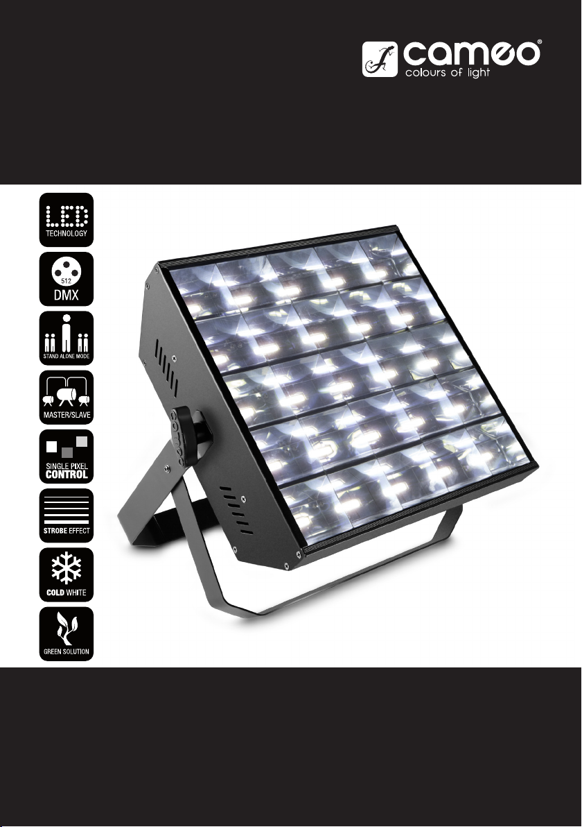
LED FLASH MATRIX 250
STROBE CHASER BLINDER
CLFM250
Page 2

CONTENTS / INHALTSVERZEICHNIS / CONTENU / CONTENIDO / TREŚĆ / CONTENUTO
ENGLISH
PREVENTIVE MEASURES 3-4
INTRODUCTION 4
CONNECTIONS, CONTROLS AND INDICATORS 5
OPERATION 6-7
SETTING UP AND MOUNTING 7
DMX TECHNOLOGY 8
TECHNICAL SPECIFICATIONS 9
MANUFACTURER INFORMATION 9
DMX CONTROL 45-52
DEUTSCH
SICHERHEITSHINWEISE 10-11
EINFÜHRUNG 11
ANSCHLÜSSE, BEDIEN- UND ANZEIGEELEMENTE 12
BEDIENUNG 13-14
AUFSTELLUNG UND MONTAGE 14
DMX TECHNIK 15
TECHNISCHE DATEN 16
HERSTELLERERKLÄRUNGEN 16
DMX STEUERUNG 45-52
FRANÇAIS
MESURES PRÉVENTIVES 17-18
INTRODUCTION 18
CONNECTEURS, CONTRÔLES ET INDICATEURS 19
UTILISATION 20-21
MISE EN PLACE ET MONTAGE 21
TECHNIQUE DMX 22
CARACTÉRISTIQUES TECHNIQUES 23
PRÉCISIONS FABRICANT 23
PILOTAGE DMX 45-52
ESPAÑOL
MEDIDAS DE SEGURIDAD 24-25
INTRODUCCIÓN 25
CONEXIONES, CONTROLES E INDICADORES 26
OPERACIÓN 27-28
INSTALACIÓN Y MONTAJE 28
TECNOLOGÍA DMX 29
CARACTERÍSTICAS TÉCNICAS 30
DECLARACIÓN DEL FABRICANTE 30
CONTROL DMX 45-52
POLSKI
ŚRODKI OSTROŻNOŚCI 31-32
WPROWADZENIE 32
ZŁĄCZA, ELEMENTY OBSŁUGI I WSKAŹNIKI 33
OBSŁUGA 34-35
USTAWIENIE I MONTAŻ 35
TECHNOLOGIA DMX 36
DANE TECHNICZNE 37
DEKLARACJE PRODUCENTA 37
STEROWANIE DMX 45-52
ITALIANO
MISURE PRECAUZIONALI 38-39
INTRODUZIONE 39
CONNESSIONI, ELEMENTI DI COMANDO E DI VISUALIZZAZIONE 40
UTILIZZO 41-42
INSTALLAZIONE E MONTAGGIO 42
TECNOLOGIA DMX 43
DATI TECNICI 44
DICHIARAZIONI DEL FABBRICANTE 44
CONTROLLO DMX 45-52
Page 3

ENGLISH
YOU‘VE MADE THE RIGHT CHOICE!
We have designed this product to operate reliably over many years. Please read this User‘s Manual carefully, so that you can begin making
optimum use of your Cameo Light product quickly. Learn more about Cameo Light on our website WWW.CAMEOLIGHT.COM.
PREVENTIVE MEASURES
1. Please read these instructions carefully.
2. Keep all information and instructions in a safe place.
3. Follow the instructions.
4. Observe all safety warnings. Never remove safety warnings or other information from the equipment.
5. Use the equipment only in the intended manner and for the intended purpose.
6. Use only sufficiently stable and compatible stands and/or mounts (for fixed installations). Make certain that wall mounts are properly installed and
secured. Make certain that the equipment is installed securely and cannot fall down.
7. During installation, observ e the applicable safety regulations for your country.
8. Never install and operate the equipment near radiators, heat registers, ovens or other sources of heat. Make certain that the equipment is
always installed so that is cooled sufficiently and cannot overheat.
9. Never place sources of ignition, e.g., burning candles, on the equipment.
10. Ventilation slits must not be blocked.
11. This appliance is designed exclusively for indoor use, do not use this equipment in the immediate vicinity of water (does not apply
to special outdoor equipment - in this case, observe the special instructions noted below). Do not expose this equipment to flammable
materials, fluids or gases.
12. Make certain that dripping or splashed water cannot enter the equipment. Do not place containers filled with liquids, such as vases or
drinking vessels, on the equipment.
13. Make certain that objects cannot fall into the device.
14. Use this equipment only with the accessories recommended and intended by the manufacturer.
15. Do not open or modify this equipment.
16. After connecting the equipment, check all cables in order to prevent damage or accidents, e.g., due to tripping hazards.
17. During transport, make certain that the equipment cannot fall down and possibly cause property damage and personal injuries.
18. If your equipment is no longer functioning properly, if fluids or objects have gotten inside the equipment or if it has been damaged in
anot her way, switch it off immediately and unplug it from the mains outlet (if it is a powered device). This equipment may only be repaired
by authorized, qualified personnel.
19. Clean the equipment using a dry cloth.
20. Comply with all applicable disposal laws in your country. During disposal of packaging, please separate plastic and paper/cardboard.
21. Plastic bags must be kept out of reach of children.
FOR EQUIPMENT THAT CONNECTS TO THE POWER MAINS:
22. CAUTION: If the power cord of the device is equipped with an earthing contact, then it must be connected to an outlet with a protective
ground. Never deactivate the protective ground of a power cord.
23. If the equipment has been exposed to strong fluctuations in temperature (for example, after transport), do not switch it on immediately.
Moisture and condensation could damage the equipment. Do not switch on the equipment until it has reached room temperature.
24. Before connecting the equipment to the power outlet, first verify that the mains voltage and frequency match the values specified on the
equipment. If the equipment has a voltage selection switch, connect the equipment to the power outlet only if the equipment values and the
mains power values match. If the included power cord or power adapter does not fit in your wall outlet, contact your electrician.
25. Do not step on the power cord. Make certain that the power cable does not become kinked, especially at the mains outlet and/or power
adapter and the equipment connector.
26. When connecting the equipment, make certain that the power cord or power adapter is always freely accessible. Always disconnect the
equipment from the power supply if the equipment is not in use or if you want to clean the equipment. Always unplug the power cord and
power adapter from the power outlet at the plug or adapter and not by pulling on the cord. Never touch the power cord and power adapter
with wet hands.
27. Whenever possible, avoid switching the equipment on and off in quick succession because otherwise this can shorten the useful life of
the equipment.
28. IMPORTANT INFORMATION: Replace fuses only with fuses of the same type and rating. If a fuse blows repeatedly, please contact an
authorised service centre.
29. To disconnect the equipment from the power mains completely, unplug the power cord or power adapter from the power outlet.
30. If your device is equipped with a Volex power connector, the mating Volex equipment connector must be unlocked before it can be removed. However, this also means that the equipment can slide and fall down if the power cable is pulled, which can lead to personal injuries
and/or other damage. For this reason, always be careful when laying cables.
31. Unplug the power cord and power adapter from the power outlet if there is a risk of a lightning strike or before extended periods of disuse.
32. The device must only be installed in a voltage-free condition (disconnect the mains plug from the mains).
33. Dust and other debris inside the unit may cause damage. The unit should be regularly serviced or cleaned (no guarantee) depending on
ambient conditions (dust etc., nicotine, fog) by qualified personnel to prevent overheating and malfunction.
34. Please keep a distance of at least 0.5 m to any combustible materials.
35. Power cables to power multiple devices must have a cross-section of at least 1.5 mm². Within the EU, the cables must correspond to
H05VV-F, or similar. Suitable cables are offered by Adam Hall. With these cables, you can connect multiple devices via the power OUT connection to the power IN connection of an additional device. Make sure that the total current consumption of all connected devices does not
exceed the specified value on all connected devices (label on the device). Make sure to keep power cable connections as short as possible.
ENGLISH
DEUTSCH
FRANCAIS
ESPAÑOL
POLSKI
ITALIANO
DMX
3
Page 4

ENGLISH
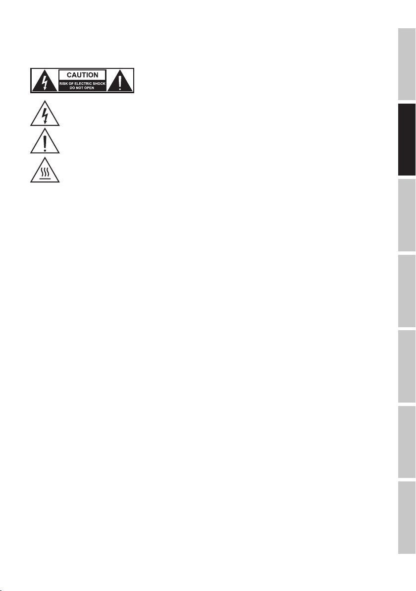
CAUTION:
To reduce the risk of electric shock, do not remove cover (or back). There are no user serviceable
parts inside. Maintenance and repairs should be exclusively carried out by qualified service
personnel.
The warning triangle with lightning symbol indicates dangerous uninsulated voltage inside the unit, which may cause an
electrical shock.
The warning triangle with exclamation mark indicates important operating and maintenance instructions.
DEUTSCHFRANCAIS
CAUTION! IMPORTANT INFORMATION ABOUT LIGHTING PRODUCTS!
1. The product has been developed for professional use in the field of event technology and is not suitable as household lighting.
2. Do not stare, even temporarily, directly into the light beam.
3. Do not look at the beam directly with optical instruments such as magnifiers.
4. Stroboscope effects may cause epileptic seizures in sensitive people! People with epilepsy should definitely avoid places where strobes are used.
Warning! This symbol indicates a hot surface. Certain parts of the housing can become hot during operation. After use, wait for
a cool-down period of at least 10 minutes before handling or transporting the device.
INTRODUCTION
LED FLASH MATRIX 250 3IN1 FX - STROBE - CHASER - BLINDER
CLFM250
CONTROL FUNCTIONS:
1-channel, 2-channel, 3-channel, 5-channel, 9-channel, 25-channel, and 30-channel DMX control
Master / Slave mode
Standalone Functions
ESPAÑOL
FEATURES:
3in1 FX - Strobe - Chaser - Blinder, 25 x 6 W high-power LEDs, high-speed Strobe (>30 Hz), 25 zones Chasing Stroboscope, Rendering of
numbers, letters and signs, Single Pixel Control, DMX 512 Control, Standalone programs, Music Control Mode, quiet fan, operating voltage
100-240 V AC, Power Consumption 125 W, stand/ mounting bracket included.
ITALIANO POLSKIDMX
4
Page 5
CONNECTIONS, CONTROLS AND INDICATORS
ENGLISH
6
1
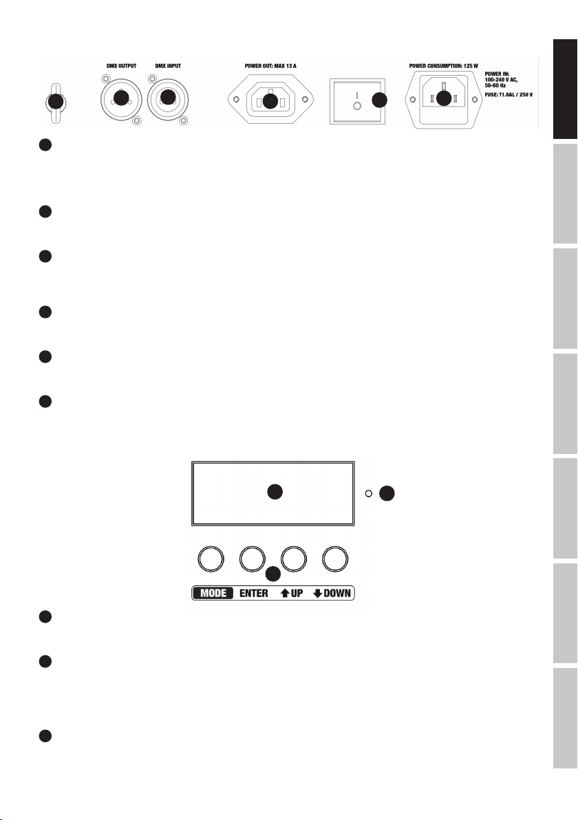
POWER IN
IEC power socket with built-in fuse holder. An appropriate power cord is included in the delivery. IMPORTANT INFORMATION: Always replace
the fuse only with a fuse of the same type with the same rating (printed on the device). If the fuse blows repeatedly, please contact an
authorised service centre.
2
POWER
On / Off switch for the power supply of the device.
3
POWER OUT
IEC mains output socket. Used to supply power to additional CAMEO spotlights. Make sure that the total current consumption in amperes (A)
of all connected devices does not exceed the specified value on the device.
4
DMX INPUT
3-pin male XLR socket for connection of a DMX controller (e.g. DMX console).
5
DMX OUTPUT
3-pin female XLR socket for looping through the DMX control signal.
6
SAFETY EYELET
Overhead installation should only be carried out by trained personnel. The spotlight must be secured with appropriate safety ropes to
prevent falling.
5
4
3
7
2
9
1
DEUTSCH
FRANCAIS
ESPAÑOL
POLSKI
8
7
LED DISPLAY
The four-digit LED display indicates the operating mode and other system information.
8
CONTROL BUTTONS
MODE: Selecting the different options for operating modes and system settings.
ENTER: Confirm value changes and program selection.
UP and DOWN: perform value changes, such as program speed and DMX address, and select programs.
9
MIC
Microphone for music control mode.
ITALIANO
DMX
5
Page 6

OPERATION
After the spotlight has been correctly connected to the mains and switched on, it is ready for use and the mode that was previously selected
is activated.
SELECTING THE DMX START ADDRESS
ENGLISH
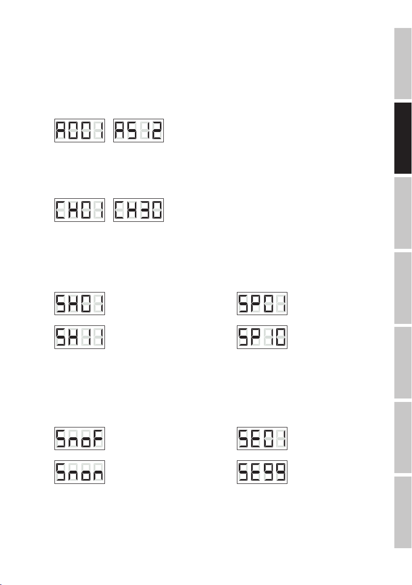
Press the MODE button repeatedly until the currently set DMX address appears on the display (A001 - A512). Using the UP and DOWN
buttons, the DMX start address can now be set as desired. Confirm the input with ENTER. The synchronous control of multiple spotlights
(same model) through a DMX control unit (e.g. DMX console) can be achieved by assigning the spotlights to an identical DMX start address
and DMX mode and connecting them using DMX cables.
-> ENTERUP/DOWN -
DEUTSCHFRANCAIS
SETTING THE DMX MODE
Press the MODE button repeatedly until one of the 7 available DMX modes is displayed (CH01, CH02, CH03, CH05, CH9, CH25, CH30). The
DMX mode can be adjusted as desired by using the UP and DOWN buttons. Confirm the input with ENTER. You will find tables with the
channels of the different DMX modes in this manual under DMX CONTROL.
-> ENTERUP/DOWN -
AUTOMATIC CONTROL
Select one of the 11 different Auto programs (SH01 - SH11) and adjust their speed (SP01 - SP10). Press the MODE button repeatedly until
of the auto programs appears on the display, select the desired program using the UP and DOWN buttons and confirm by pressing ENTER.
Press the MODE button once to access the menu item for setting the program speed. One of the 10 speed levels will be shown on the
display and you can use the UP and DOWN buttons to select the desired speed as required (SP01 - SP10). Confirm the input with ENTER.
UP/DOWN -> MODE -> ENTERUP/DOWN
ESPAÑOL
MUSIC CONTROL
Select the Music control mode to control the spot via the built-in microphone (bass pulses). Press the MODE button repeatedly until “SnoF”
or “Snon” appears on the display. Now use the UP and DOWN buttons to select the menu item “SnoF” for “Music control disabled” or
“Snon” for “Music control enabled” and press ENTER to confirm. Press the MODE button once to access the menu item for adjusting the microphone sensitivity. The currently set value will be shown on the display and you can use the UP and DOWN buttons to select the sensitivity
with which the spotlight reacts to sound, as required (SE01 = minimum sensitivity, SE99 = maximum sensitivity). Confirm with ENTER.
-> ENTER
- -
-> ENTERUP/DOWN -> MODE -> ENTERUP/DOWN
/ -
ITALIANO POLSKIDMX
6
Page 7

STROBOSCOPE
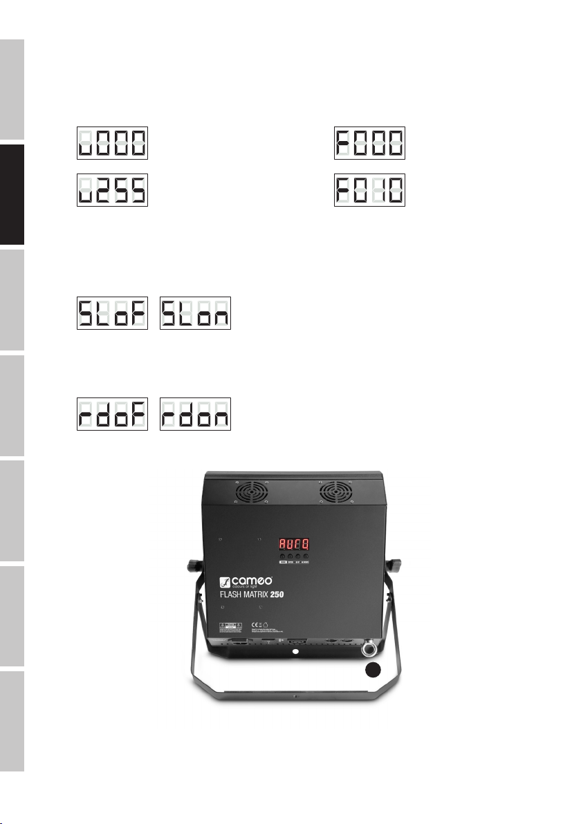
Press the MODE button repeatedly until the brightness value between v000 and v255 appears on the display (value xxx). Using the UP and
DOWN buttons, adjust the brightness as required (v000 = blackout, v001 = minimum brightness, v255 = maximum brightness) and confirm
the entry with ENTER. Press the MODE button once to access the menu item for adjusting the strobe speed. The currently set value will
be shown on the display and you can use the UP and DOWN buttons to make adjustments as required (F000 = minimum speed, F010 =
maximum speed). To confirm your selection and activate the strobe, press ENTER again.
ENGLISH
UP/DOWN -> MODE -> ENTERUP/DOWN
SLAVE MODE
Press the MODE button repeatedly until “SLoF” or “SLon” appears on the display. Now use the UP and DOWN buttons to select “SLoF” for
“Slave operation disabled” or “SLon” for “Slave mode enabled” and press ENTER to confirm. When the slave mode is enabled, connect the
slave and the master unit (same model) using a DMX cable and activate one of the standalone modes on the master unit. Now the slave unit
follows the master unit.
ROTATE THE DISPLAY BY 180
Press the MODE button repeatedly until “rdoF” or “rdon” appears on the display. Now use the UP and DOWN buttons to select “rdoF” for
“Display rotation disabled” or “rdon” for “Display rotation enabled” and press ENTER to confirm.
-> ENTER
- -
-> ENTERUP/DOWN /
-> ENTERUP/DOWN /
SETTING UP AND MOUNTING
DEUTSCH
FRANCAIS
ESPAÑOL
POLSKI
A
Thanks to the integrated double bracket, the spotlight can be placed in a suitable location on a flat surface. Mounting on a truss is performed with the help of a suitable truss clamp (not included). Make sure that the connection to the mounting bracket is solid, and secure
the device with a suitable safety rope to the safety eyelet provided (A). Important Notice: Overhead installation should only be carried out by
trained personnel.
ITALIANO
DMX
7
Page 8
DMX TECHNOLOGY
DMX-512
DMX (Digital Multiplex) is the designation for a universal transmission protocol for
communications between corresponding devices and controllers. A DMX controller sends
DMX data to the connected DMX device(s). The DMX data is always transmitted as a serial
ENGLISH
data stream that is forwarded from one connected device to the next via the "DMX IN" and
"DMX OUT" connectors (XLR plug-type connectors) that are found on every DMX-capable
device, provided the maximum number of devices does not exceed 32 units. The last device
in the chain needs to be equipped with a terminator (terminating resistor).
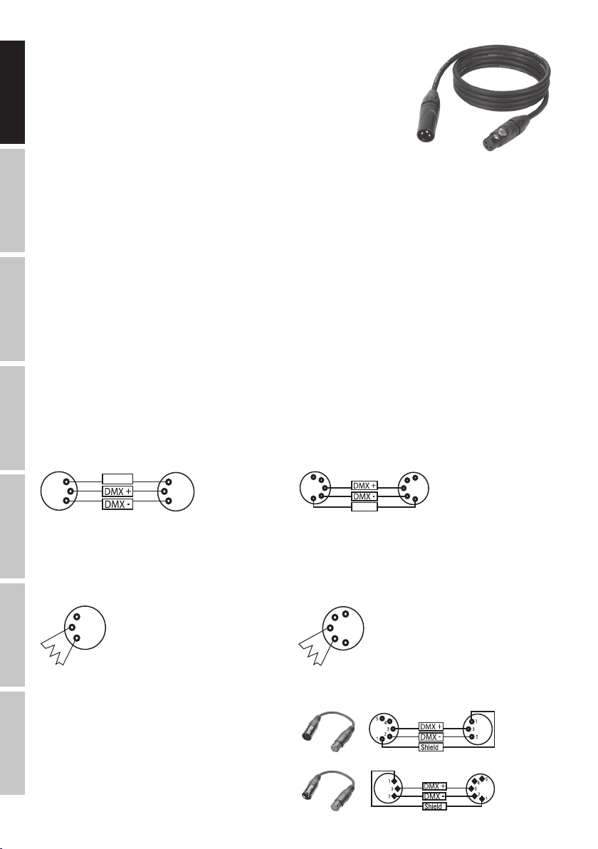
DMX CONNECTION
DMX is the common "language" via which a very wide range of types and models of equipment from various manufacturers can
be connected with one another and controlled via a central controller, provided that all of the devices and the controller are DMX
compatible. For optimum data transmission, it is necessary to keep the connecting cables between the individual devices as short as
possible. The order in which the devices are integrated in the DMX network has no influence on the addresses. Thus the device with
DEUTSCHFRANCAIS
the DMX address 1 can be located at any position in the (serial) DMX chain: at the beginning, at the end or somewhere in the middle.
If the DMX address 1 is assigned to a device, the controller "knows" that it should send all data allocated to address 1 to this device
regardless of its position in the DMX network.
SERIAL CONNECTION OF MULTIPLE LIGHTS
1. Connect the male XLR connector (3-pin or 5-pin) of the DMX cable to the DMX output (female XLR socket) of the first DMX device
(e.g. DMX-Controller).
2. Connect the female 3-pin XLR connector of the DMX cable connected to the first projector to the DMX input (male 3-pin socket)
of the next DMX device. In the same way, connect the DMX output of this device to the DMX input of the next device and repeat until
all devices have been connected. Please note that as a rule, DMX devices are connected in series and connections cannot be shared
without active splitters. The maximum number of DMX devices in a DMX chain should not exceed 32 units.
The Adam Hall 3 STAR, 4 STAR, and 5 STAR product ranges include an extensive selection of suitable cables.
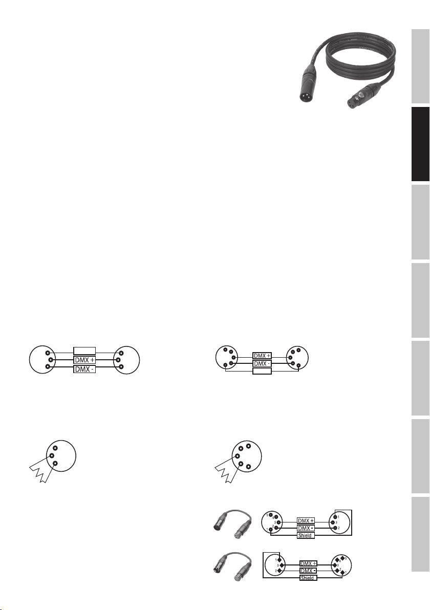
DMX CABLES
When fabricating your own cables, always observe the illustrations on this page. Never connect the shielding of the cable to the ground
contact of the plug, and always make certain that the shielding does not come into contact with the housing of the XLR plug. If the shielding
is connected to the ground, this can lead to short-circuiting and system malfunctions.
ESPAÑOL
Pin Assignment
DMX cable with 3-pin XLR connectors: DMX cable with 5-pin XLR connectors (pin 4 and 5 are not used):
1
3
2
Shield
1
3
2
5
4
3
2
1
Shield
5
4
3
2
1
DMX TERMINATORS (TERMINATING RESISTORS)
To prevent system errors, the last device in a DMX chain needs to be equipped with a terminating resistor (120 ohm, 1/4 Watt).
3-pin XLR connector with a terminating resistor: K3DMXT3
5-pin XLR connector with a terminating resistor: K3DMXT5
Pin Assignment
3-pin XLR connector: 5-pin XLR connector:
1
3
2
5
4
3
2
1
ITALIANO POLSKIDMX
DMX ADAPTER
The combination of DMX devices with 3-pin connectors and DMX devices with 5-pin connectors in a DMX chain is possible with suitable
adapters.
Pin Assignment
DMX Adapter 5-pin XLR male to 3-pin XLR female: K3DGF0020
Pins 4 and 5 are not used.
Pin Assignment
DMX Adapter 3-pin XLR male to 5-pin XLR female: K3DHM0020
Pins 4 and 5 are not used.
8
Page 9

TECHNICAL SPECIFICATIONS
Model Name: CLFM250
Product Type: 3in1 FX Matrix
Type: LED Strobe - Chaser - Blinder
LED Colour Spectrum: Cool white
Number of LEDs: 25
LED Type: 6 W
Beam Angle (Beam): 50°
Beam Angle (Field): 74°
DMX Input: 3-pin XLR male
DMX Output: 3-pin XLR female
DMX Mode: 1-channel, 2-channel, 3-channel, 5-channel,9-channel, 25-channel, 30-channel
DMX Functions: Master Dimmer, Dimmer 1-25, Auto programs 1-11, Stroboscope (>30 Hz), flash
duration, Music control
Standalone Functions: Strobe, Auto Programs 1-11, Music Control, Master/Slave mode
Control: DMX512
Controls: Mode, Enter, Up, Down, On/Off Switch
Indicators: LED display
Operating Voltage: 100 - 240 V AC / 50 - 60 Hz
Power Consumption: 125 W.
Illuminance (@ 1 m): 3730 lx
Light Output: 9216 lm
Power Connector: IEC power input and output
Fuse: T1.6 AL / 250 V (5 x 20 mm)
Temperature (during operation): 0°C - 40°C
Relative Humidity: < 85% non-condensing
Housing Material: Metal, ABS
Housing Colour: Black
Housing Cooling: Low-noise fan
Dimensions (W x H x D, excluding bracket): 305 x 310 x 105 mm
Weight: 4 kg
Other Features: Power cable and mounting bracket included
ENGLISH
DEUTSCH
FRANCAIS
ESPAÑOL
POLSKI
MANUFACTURER´S DECLARATIONS
MANUFACTURER‘S WARRANTY & LIMITATIONS OF LIABILITY
You can find our current warranty conditions and limitations of liability at: http://www.adamhall.com/media/shop/downloads/documents/
manufacturersdeclarations.pdf. To request warranty service for a product, please contact Adam Hall GmbH, Daimler Straße 9, 61267 Neu
Anspach / Email: Info@adamhall.com / +49 (0)6081 / 9419-0.
CORRECT DISPOSAL OF THIS PRODUCT
(valid in the European Union and other European countries with a differentiated waste collection system)
This symbol on the product, or on its documents indicates that the device may not be treated as household waste. This is to avoid
environmental damage or personal injury due to uncontrolled waste disposal. Please dispose of this product separately from other waste
and have it recycled to promote sustainable economic activity. Household users should contact either the retailer where they purchased
this product, or their local government office, for details on where and how they can recycle this item in an environmentally friendly manner.
Business users should contact their supplier and check the terms and conditions of the purchase contract. This product should not be mixed
with other commercial waste for disposal.
ITALIANO
DMX
9
Page 10

DEUTSCH
SIE HABEN DIE RICHTIGE WAHL GETROFFEN!
Dieses Gerät wurde unter hohen Qualitätsanforderungen entwickelt und gefertigt, um viele Jahre einen reibungslosen Betrieb zu gewährleisten. Bitte lesen Sie diese Bedienungsanleitung sorgfältig, damit Sie Ihr neues Produkt von Cameo Light schnell und optimal einsetzen
können. Weitere Informationen über Cameo Light erhalten Sie auf unserer Website WWW.CAMEOLIGHT.COM.
ENGLISH
SICHERHEITSHINWEISE
1. Lesen Sie diese Anleitung bitte sorgfältig durch.
2. Bewahren Sie alle Informationen und Anleitungen an einem sicheren Ort auf.
3. Befolgen Sie die Anweisungen.
4. Beachten Sie alle Warnhinweise. Entfernen Sie keine Sicherheitshinweise oder andere Informationen vom Gerät.
5. Verwenden Sie das Gerät nur in der vorgesehenen Art und Weise.
6. Verwenden Sie ausschließlich stabile und passende Stative bzw. Befestigungen (bei Festinstallationen). Stellen Sie sicher, dass Wandhalterungen
ordnungsgemäß installiert und gesichert sind. Stellen Sie sicher, dass das Gerät sicher installiert ist und nicht herunterfallen kann.
7. Beachten Sie bei der Installation die für Ihr Land geltenden Sicherheitsvorschriften.
DEUTSCHFRANCAIS
8. Installieren und betreiben Sie das Gerät nicht in der Nähe von Heizkörpern, Wärmespeichern, Öfen oder sonstigen Wärmequellen. Sorgen
Sie dafür, dass das Gerät immer so installiert ist, dass es ausreichend gekühlt wird und nicht überhitzen kann.
9. Platzieren Sie keine Zündquellen wie z.B. brennende Kerzen auf dem Gerät.
10. Lüftungsschlitze dürfen nicht blockiert werden.
11. Das Gerät wurde ausschließlich für die Verwendung in Innenräumen entwickelt, betreiben Sie das Gerät nicht in unmittelbarer Nähe von
Wasser (gilt nicht für spezielle Outdoor Geräte - beachten Sie in diesem Fall bitte die im Folgenden vermerkten Sonderhinweise). Bringen Sie
das Gerät nicht mit brennbaren Materialien, Flüssigkeiten oder Gasen in Berührung.
12. Sorgen Sie dafür, dass kein Tropf- oder Spritzwasser in das Gerät eindringen kann. Stellen Sie keine mit Flüssigkeit gefüllten Behältnisse
wie Vasen oder Trinkgefäße auf das Gerät.
13. Sorgen Sie dafür, dass keine Gegenstände in das Gerät fallen können.
14. Betreiben Sie das Gerät nur mit dem vom Hersteller empfohlenen und vorgesehenen Zubehör.
15. Öffnen Sie das Gerät nicht und verändern Sie es nicht.
16. Überprüfen Sie nach dem Anschluss des Geräts alle Kabelwege, um Schäden oder Unfälle, z. B. durch Stolperfallen zu vermeiden.
17. Achten Sie beim Transport darauf, dass das Gerät nicht herunterfallen und dabei möglicherweise Sach- und Personenschäden verursachen kann.
18. Wenn Ihr Gerät nicht mehr ordnungsgemäß funktioniert, Flüssigkeiten oder Gegenstände in das Geräteinnere gelangt sind, oder das Gerät
anderweitig beschädigt wurde, schalten Sie es sofort aus und trennen es von der Netzsteckdose (sofern es sich um ein aktives Gerät handelt).
Dieses Gerät darf nur von autorisiertem Fachpersonal repariert werden.
19. Verwenden Sie zur Reinigung des Geräts ein trockenes Tuch.
20. Beachten Sie alle in Ihrem Land geltenden Entsorgungsgesetze. Trennen Sie bei der Entsorgung der Verpackung bitte Kunststoff und
ESPAÑOL
Papier bzw. Kartonagen voneinander.
21. Kunststoffbeutel müssen außer Reichweite von Kindern aufbewahrt werden.
BEI GERÄTEN MIT NETZANSCHLUSS:
22. ACHTUNG: Wenn das Netzkabel des Geräts mit einem Schutzkontakt ausgestattet ist, muss es an einer Steckdose mit Schutzleiter
angeschlossen werden. Deaktivieren Sie niemals den Schutzleiter eines Netzkabels.
23. Schalten Sie das Gerät nicht sofort ein, wenn es starken Temperaturschwankungen ausgesetzt war (beispielsweise nach dem Transport).
Feuchtigkeit und Kondensat könnten das Gerät beschädigen. Schalten Sie das Gerät erst ein, wenn es Zimmertemperatur erreicht hat.
24. Bevor Sie das Gerät an die Steckdose anschließen, prüfen Sie zuerst, ob die Spannung und die Frequenz des Stromnetzes mit den auf
dem Gerät angegebenen Werten übereinstimmen. Verfügt das Gerät über einen Spannungswahlschalter, schließen Sie das Gerät nur an die
Steckdose an, wenn die Gerätewerte mit den Werten des Stromnetzes übereinstimmen. Wenn das mitgelieferte Netzkabel bzw. der mitgelieferte Netzadapter nicht in Ihre Netzsteckdose passt, wenden Sie sich an Ihren Elektriker.
25. Treten Sie nicht auf das Netzkabel. Sorgen Sie dafür, dass spannungsführende Kabel speziell an der Netzbuchse bzw. am Netzadapter
und der Gerätebuchse nicht geknickt werden.
26. Achten Sie bei der Verkabelung des Geräts immer darauf, dass das Netzkabel bzw. der Netzadapter stets frei zugänglich ist. Trennen Sie
das Gerät stets von der Stromzuführung, wenn das Gerät nicht benutzt wird, oder Sie das Gerät reinigen möchten. Ziehen Sie Netzkabel und
Netzadapter immer am Stecker bzw. am Adapter und nicht am Kabel aus der Steckdose. Berühren Sie Netzkabel und Netzadapter niemals
mit nassen Händen.
27. Schalten Sie das Gerät möglichst nicht schnell hintereinander ein und aus, da sonst die Lebensdauer des Geräts beeinträchtigt werden könnte.
ITALIANO POLSKIDMX
28. WICHTIGER HINWEIS: Ersetzen Sie Sicherungen ausschließlich durch Sicherungen des gleichen Typs und Wertes. Sollte eine Sicherung
wiederholt auslösen, wenden Sie sich bitte an ein autorisiertes Servicezentrum.
29. Um das Gerät vollständig vom Stromnetz zu trennen, entfernen Sie das Netzkabel bzw. den Netzadapter aus der Steckdose.
30. Wenn Ihr Gerät mit einem Volex-Netzanschluss bestückt ist, muss der passende Volex-Gerätestecker entsperrt werden, bevor er entfernt
werden kann. Das bedeutet aber auch, dass das Gerät durch ein Ziehen am Netzkabel verrutschen und herunterfallen kann, wodurch Personen verletzt werden und/oder andere Schäden auftreten können. Verlegen Sie Ihre Kabel daher immer sorgfältig.
31. Entfernen Sie Netzkabel und Netzadapter aus der Steckdose bei Gefahr eines Blitzschlags oder wenn Sie das Gerät länger nicht verwenden.
32. Das Gerät darf nur im spannungsfreien Zustand (Trennung des Netzsteckers vom Stromnetz) installiert werden.
33. Staub und andere Ablagerungen im Inneren des Geräts können es beschädigen. Das Gerät sollte je nach Umgebungsbedingungen
(Staub, Nikotin, Nebel etc.) regelmäßig von qualifiziertem Fachpersonal gewartet bzw. gesäubert werden (keine Garantieleistung),
um Überhitzung und Fehlfunktionen zu vermeiden.
34. Der Abstand zu brennbaren Materialien muss mindestens 0,5 m betragen.
35. Netzleitungen zur Spannungsversorgung mehrerer Geräte müssen mindestens 1,5 mm² Aderquerschnitt aufweisen. In der EU müssen
10
Page 11
die Leitungen H05VV-F, oder gleichartig, entsprechen. Geeignete Leitungen werden von Adam Hall angeboten. Mit diesen Leitungen können
Sie mehrere Geräte über den Power out Anschluss mit dem Power IN Anschluss eines weiteren Gerätes verbinden. Beachten Sie, dass die
gesamte Stromaufnahme aller angeschlossenen Geräte den vorgegebenen Wert nicht überschreitet (Aufdruck auf dem Gerät). Achten Sie
darauf, Netzleitungen so kurz wie möglich zu halten.
ACHTUNG
Entfernen Sie niemals die Abdeckung, da sonst das Risiko eines elektrischen Schlages besteht. Im
Inneren des Geräts befinden sich keine Teile, die vom Bediener repariert oder gewartet werden können.
Lassen Sie Wartung und Reparaturen ausschließlich von qualifiziertem Servicepersonal durchführen.
Das gleichseitige Dreieck mit Blitzsymbol warnt vor nichtisolierten, gefährlichen Spannungen im Geräteinneren, die einen
elektrischen Schlag verursachen können.
Das gleichseitige Dreieck mit Ausrufungszeichen kennzeichnet wichtige Bedienungs- und Wartungshinweise.
Warnung! Dieses Symbol kennzeichnet heiße Oberflächen. Während des Betriebs können bestimmte Teile des Gehäuses heiß
werden. Berühren oder transportieren Sie das Gerät nach einem Einsatz erst nach einer Abkühlzeit von mindestens 10 Minuten.
ENGLISH
DEUTSCH
VORSICHT! WICHTIGE HINWEISE IN BEZUG AUF LICHT-PRODUKTE!
1. Das Produkt ist für den professionellen Einsatz im Bereich der Veranstaltungstechnik entwickelt worden und ist nicht für die Raumbeleuchtung in Haushalten geeignet.
2. Blicken Sie niemals, auch nicht kurzzeitig, direkt in den Lichtstrahl.
3. Blicken Sie niemals mit optischen Geräten wie Vergrößerungsgläsern in den Lichtstrahl.
4. Stoboskopeffekte können unter Umständen bei empfindlichen Menschen epileptische Anfälle auslösen! Epilepsiekranke Menschen sollten
daher unbedingt Orte meiden, an denen Stroboskope eingesetzt werden.
EINFÜHRUNG
LED FLASH MATRIX 250 3IN1 FX - STROBE - CHASER - BLINDER
CLFM250
STEUERUNGSFUNKTIONEN:
1-Kanal, 2-Kanal, 3-Kanal, 5-Kanal, 9-Kanal, 25-Kanal, 30-Kanal DMX-Steuerung
Master / Slave Betrieb
Standalone Funktionen
EIGENSCHAFTEN:
3in1 FX - Strobe - Chaser - Blinder, 25 x 6 W High Power LEDs, High-Speed Stroboskop (>30 Hz), 25 Zonen Chasing Stroboskop, Darstellung
von Zahlen, Buchstaben und Zeichen, Single Pixel Control, DMX-512 Steuerung, Standalone Programme, Musiksteuerung, leise Lüfter,
Betriebsspannung 100-240V AC, Leistungsaufnahme 125 W, Stand- / Montagebügel inklusive.
FRANCAIS
ESPAÑOL
POLSKI
ITALIANO
11
DMX
Page 12

ANSCHLÜSSE, BEDIEN- UND ANZEIGEELEMENTE
6
ENGLISH
1
POWER IN
IEC Netzbuchse mit integriertem Sicherungshalter. Ein geeignetes Netzkabel befindet sich im Lieferumfang. WICHTIGER HINWEIS: Ersetzen
Sie die Sicherung ausschließlich durch eine Sicherung des gleichen Typs und mit gleichen Werten entsprechend des Aufdrucks auf dem
Gerät! Sollte die Sicherung wiederholt auslösen, wenden Sie sich bitte an ein autorisiertes Servicezentrum.
2
POWER
DEUTSCHFRANCAIS
Ein- / Ausschalter für die Spannungsversorgung des Geräts.
3
POWER OUT
IEC Netzausgangsbuchse. Dient der Netzversorgung weiterer CAMEO Scheinwerfer. Achten Sie darauf, dass die gesamte Stromaufnahme
aller angeschlossenen Geräte den auf dem Gerät in Ampere (A) angegebenen Wert nicht überschreitet.
4
DMX INPUT
Männliche 3-Pol XLR-Buchse zum Anschließen eines DMX-Kontrollgeräts (z.B. DMX-Pult).
5
DMX OUTPUT
Weibliche 3-Pol XLR-Buchse zum Weiterleiten des DMX-Steuersignals.
6
SICHERUNGSÖSE
Überkopfmontage darf nur von dafür ausgebildetem Personal durchgeführt werden. Der Scheinwerfer ist dabei mit geeigneten Sicherungs-
ESPAÑOL
seilen gegen Herabfallen zu sichern.
5
4
3
7
2
9
1
8
7
LED DISPLAY
ITALIANO POLSKIDMX
Das vierstellige LED-Display zeigt Betriebsart und weitere Systeminformationen an.
8
BEDIENTASTEN
MODE: Auswählen der Betriebsart und Einstellungsoptionen.
ENTER: Bestätigen von Wertänderungen und Programmauswahl.
UP und DOWN: Wertänderungen durchführen, wie z.B. Programmgeschwindigkeit und DMX-Adresse, sowie Auswahl der Programme.
9
MIC
Mikrofon für die Betriebsart Musiksteuerung.
12
Page 13
BEDIENUNG
Sobald der Scheinwerfer korrekt am Stromnetz angeschlossen und eingeschaltet wird, ist er betriebsbereit und die Betriebsart, die zuvor
angewählt war, wird aktiviert.
DMX-STARTADRESSE EINSTELLEN
Drücken Sie die MODE-Taste so oft, bis im Display die aktuell eingestellte DMX-Adresse angezeigt wird (A001 - A512). Mit Hilfe der Tasten
UP und DOWN kann nun die DMX-Startadresse wunschgemäß eingestellt werden. Bestätigen Sie die Eingabe mit ENTER. Die synchrone
Ansteuerung mehrerer Scheinwerfer des gleichen Modells durch ein DMX-Steuergerät (z.B. DMX-Pult) erreichen Sie, indem Sie die Scheinwerfer auf eine identische DMX-Startadresse und die gleiche DMX-Betriebsart einstellen und mit Hilfe von DMX-Kabeln verbinden.
-> ENTERUP/DOWN -
DMX-BETRIEBSART EINSTELLEN
Drücken Sie die MODE-Taste so oft, bis im Display eine der 7 verfügbaren DMX-Betriebsarten angezeigt wird (CH01, CH02, CH03, CH05,
CH9, CH25, CH30). Die DMX-Betriebsart kann nun mit Hilfe der Tasten UP und DOWN wunschgemäß eingestellt werden. Bestätigen Sie die
Eingabe mit ENTER. Tabellen mit der Kanalbelegung der verschiedenen DMX-Modi finden Sie in dieser Anleitung unter DMX-STEUERUNG.
-> ENTERUP/DOWN -
AUTOMATISCHE STEUERUNG
Wählen Sie eines der 11 verfügbaren Auto-Programme aus (SH01 - SH11) und stellen deren Laufgeschwindigkeit ein (SP01 - SP10).
Drücken Sie die MODE-Taste so oft, bis im Display eines der Auto-Programme angezeigt wird, wählen mit Hilfe der Tasten UP und DOWN ein
Programm aus und bestätigen mit ENTER. Drücken Sie nun einmal auf MODE, um zum Menüpunkt für die Einstellung der Programm-Laufgeschwindigkeit zu gelangen. Im Display wird nun eine der 10 Geschwindigkeitsstufen angezeigt und Sie können mit Hilfe der Tasten UP
und DOWN die Einstellung wunschgemäß vornehmen (SP01 - SP10). Bestätigen Sie die Eingabe mit ENTER.
ENGLISH
DEUTSCH
FRANCAIS
ESPAÑOL
UP/DOWN -> MODE -> ENTERUP/DOWN
MUSIKSTEUERUNG
Wählen Sie die Betriebsart Musiksteuerung, um den Scheinwerfer über das integrierte Mikrofon steuern zu lassen (Bassimpulse). Drücken
Sie die MODE-Taste so oft, bis im Display „SnoF“ oder „Snon“ angezeigt wird. Wählen Sie nun mit Hilfe der Tasten UP und DOWN den
Menüpunkt „SnoF“ für „Musiksteuerung deaktiviert“ und „Snon“ für „Musiksteuerung aktiviert“ aus und bestätigen mit ENTER. Drücken
Sie nun einmal auf MODE, um zum Menüpunkt für die Einstellung der Mikrofonempfindlichkeit zu gelangen. Im Display wird nun der aktuell
eingestellte Wert angezeigt und Sie können mit Hilfe der Tasten UP und DOWN die Empfindlichkeit, mit der der Scheinwerfer auf Geräusche
reagieren soll, wunschgemäß einstellen (SE01 = minimale Empfindlichkeit, SE99 = maximale Empfindlichkeit). Bestätigen Sie mit ENTER.
-> ENTER
- -
-> ENTERUP/DOWN -> MODE -> ENTERUP/DOWN
/ -
POLSKI
ITALIANO
DMX
13
Page 14
STROBOSKOP
Drücken Sie die MODE-Taste so oft, bis im Display der Wert der Helligkeit von v000 bis v255 angezeigt wird (value xxx). Mit Hilfe der Tasten
UP und DOWN stellen Sie nun die Helligkeit wunschgemäß ein (v000 = blackout, v001 = minimale Helligkeit, v255 = maximale Helligkeit)
und bestätigen die Eingabe mit ENTER. Drücken Sie nun einmal auf MODE, um zum Menüpunkt für die Einstellung der Stroboskopgeschwindigkeit zu gelangen. Im Display wird nun der aktuell eingestellte Wert angezeigt und Sie können mit Hilfe der Tasten UP und DOWN
wunschgemäß Änderungen vornehmen (F000 = minimale Geschwindigkeit, F010 = maximale Geschwindigkeit). Um zu bestätigen und den
ENGLISH
Stroboskop-Effekt zu aktivieren, drücken Sie auf ENTER.
UP/DOWN -> MODE -> ENTERUP/DOWN
-> ENTER
- -
DEUTSCHFRANCAIS
SLAVE-BETRIEB
Drücken Sie die MODE-Taste so oft, bis im Display „SLoF“ oder „SLon“ angezeigt wird. Wählen Sie nun mit Hilfe der Tasten UP und DOWN
„SLoF“ für „Slave-Betrieb deaktiviert“ aus und „SLon“ für „Slave-Betrieb aktiviert“ aus und bestätigen mit ENTER. Ist der Slave-Betrieb
aktiviert, verbinden Sie die Slave- und die Master-Einheit (gleiches Modell) mit Hilfe eines DMX-Kabels und aktivieren in der Master-Einheit
eine der Standalone Betriebsarten. Nun folgt die Slave-Einheit der Master-Einheit.
-> ENTERUP/DOWN /
ANZEIGE UM 180° DREHEN
Drücken Sie die MODE-Taste so oft, bis im Display “rdoF” oder “rdon” angezeigt wird. Wählen Sie nun mit Hilfe der Tasten UP und DOWN
“rdoF” für “Anzeigen-Drehung deaktiviert” aus und “rdon” für “Anzeigen-Drehung aktiviert” aus und bestätigen mit ENTER.
-> ENTERUP/DOWN /
ESPAÑOL
AUFSTELLUNG UND MONTAGE
ITALIANO POLSKIDMX
A
Dank des integrierten Doppelbügels kann der Scheinwerfer an einer geeigneten Stelle auf eine ebene Fläche gestellt werden. Die Montage
an einer Traverse erfolgt mit Hilfe einer geeigneten Traversenklemme (nicht im Lieferumfang enthalten). Sorgen Sie für eine feste Verbindung am Montagebügel und sichern Sie den Scheinwerfer mit einem geeigneten Sicherungsseil an der dafür vorgesehenen Sicherungsöse
(A). Wichtiger Hinweis: Überkopfmontage darf nur von dafür ausgebildetem Personal durchgeführt werden.
14
Page 15
DMX TECHNIK
DMX-512
DMX (Digital Multiplex) ist die Bezeichnung für ein universelles Übertragungsprotokoll für
die Kommunikation zwischen entsprechenden Geräten und Controllern. Ein DMX-Controller
sendet DMX-Daten an das/die angeschlossene(n) DMX-Gerät(e). Die DMX-Datenübertragung
erfolgt stets als serieller Datenstrom, der über die an jedem DMX-fähigen Gerät vorhandenen
DMX IN- und DMX OUT-Anschlüsse (XLR-Steckverbinder) von einem angeschlossenen
Gerät an das nächste weitergeleitet wird, wobei die maximale Anzahl der Geräte 32 nicht
überschreiten darf. Das letzte Gerät der Kette ist mit einem Abschlussstecker (Terminator) zu
bestücken.
DMX-VERBINDUNG:
DMX ist die gemeinsame "Sprache", über die sich die unterschiedlichsten Gerätetypen und Modelle verschiedener Hersteller
miteinander verkoppeln und über einen zentralen Controller steuern lassen, sofern sämtliche Geräte und der Controller DMXkompatibel sind. Für eine optimale Datenübertragung ist es erforderlich, die Verbindungskabel zwischen den einzelnen Geräten so
kurz wie möglich zu halten. Die Reihenfolge, in der die Geräte in das DMX-Netzwerk eingebunden sind, hat keinen Einfluss auf die
Adressierung. So kann sich das Gerät mit der DMX-Adresse 1 an einer beliebigen Position in der (seriellen) DMX-Kette befinden, am
Anfang, am Ende oder irgendwo in der Mitte. Wird einem Gerät die DMX-Adresse 1 zugewiesen, "weiß" der Controller, dass er alle
der Adresse 1 zugeordneten Daten an dieses Gerät senden soll, ungeachtet seiner Position im DMX-Verbund.
SERIELLE VERKOPPLUNG MEHRERER SCHEINWERFER
1. Verbinden Sie den männlichen XLR-Stecker (3-Pol oder 5-Pol) des DMX-Kabels mit dem DMX-Ausgang (weibliche XLR-Buchse)
des ersten DMX-Geräts (z.B. DMX-Controller).
2. Verbinden Sie den weibliche XLR-Stecker des an den ersten Scheinwerfer angeschlossenen DMX-Kabels mit dem DMX-Eingang
(männliche XLR-Buchse) des nächsten DMX-Geräts. Verbinden Sie den DMX-Ausgang dieses Geräts in der gleichen Weise mit dem
DMX-Eingang des nächsten Geräts und so weiter. Bitte beachten Sie, dass DMX-Geräte grundsätzlich seriell verschaltet werden und
die Verbindungen nicht ohne aktiven Splitter geteilt werden können. Die maximale Anzahl der DMX-Geräte einer DMX-Kette darf 32
nicht überschreiten.
Eine umfangreiche Auswahl geeigneter DMX-Kabel finden Sie in den Adam Hall Produktlinien 3 STAR, 4 STAR und 5 STAR.
DMX-KABEL:
Beachten Sie bei der Anfertigung eigener Kabel unbedingt die Abbildungen auf dieser Seite. Verbinden Sie auf keinen Fall die Abschirmung
des Kabels mit dem Massekontakt des Steckers, und achten Sie darauf, dass die Abschirmung nicht mit dem XLR-Steckergehäuse in
Kontakt kommt. Hat die Abschirmung Massekontakt, kann dies zu Systemfehlern führen.
Steckerbelegung:
DMX-Kabel mit 3-Pol XLR-Steckern: DMX-Kabel mit 5-Pol XLR-Steckern (Pin 4 und 5 sind nicht belegt.):
1
3
2
DMX-ABSCHLUSSSTECKER (TERMINATOR):
Um Systemfehler zu vermeiden, ist das letzte Gerät einer DMX-Kette mit einem Abschlusswiderstand zu bestücken (120 Ohm, 1/4 Watt).
3-Pol XLR-Stecker mit Abschlusswiderstand: K3DMXT3
5-Pol XLR-Stecker mit Abschlusswiderstand: K3DMXT5
Steckerbelegung:
3-Pol XLR-Stecker: 5-Pol XLR-Stecker:
Shield
1
3
2
1
3
2
5
4
3
2
1
Shield
5
4
3
2
1
5
4
3
2
1
ENGLISH
DEUTSCH
FRANCAIS
ESPAÑOL
POLSKI
ITALIANO
DMX-ADAPTER:
Die Kombination von DMX-Geräten mit 3-Pol Anschlüssen und DMX-Geräten mit 5-Pol Anschlüssen in einer DMX-Kette ist mit Hilfe von
Adaptern ebenso möglich.
Steckerbelegung
DMX-Adapter 5-Pol XLR male auf 3-Pol XLR female: K3DGF0020
Pin 4 und 5 sind nicht belegt.
Steckerbelegung
DMX-Adapter 3-Pol XLR male auf 5-Pol XLR female: K3DHM0020
Pin 4 und 5 sind nicht belegt.
DMX
15
Page 16

TECHNISCHE DATEN
Modellbezeichnung: CLFM250
Produktart: 3in1 FX Matrix
Typ: LED Strobe - Chaser - Blinder
ENGLISH
Farbspektrum LED: Kaltweiß
LED Anzahl: 25
LED Typ: 6 W
Abstrahlwinkel (Beam): 50°
Abstrahlwinkel (Field): 74°
DMX-Eingang: 3-Pol XLR männlich
DMX-Ausgang: 3-Pol XLR weiblich
DMX-Modus: 1-Kanal, 2-Kanal, 3-Kanal, 5-Kanal, 9-Kanal, 25-Kanal, 30-Kanal
DEUTSCHFRANCAIS
DMX Funktionen: Master Dimmer, Dimmer 1-25, Auto Programme 1-11, Stroboskop (>30 Hz), Blitzdauer,
Standalone Funktionen: Stroboskop, Auto Programme 1-11, Musiksteuerung, Master/Slave-Betrieb
Steuerung: DMX512
Bedienelemente: Mode, Enter, Up, Down, Ein-/Aus-Schalter
Anzeigeelemente: LED Display
Betriebsspannung: 100 - 240 V AC / 50 - 60 Hz
Leistungsaufnahme: 125 W
Beleuchtungsstärke (@ 1m): 3730 lx
Lichtstrom: 9216 lm
Stromversorgungsanschluss: IEC Ein- und Ausgang
Sicherung: T1,6AL / 250V (5 x 20 mm)
Umgebungstemperatur (in Betrieb): 0°C - 40°C
Relative Luftfeuchtigkeit: < 85%, nicht kondensierend
ESPAÑOL
Gehäusematerial: Metall, ABS
Gehäusefarbe: schwarz
Gehäusekühlung: leise Lüfter
Abmessungen (B x H x T, ohne Montagebügel): 305 x 310 x 105 mm
Gewicht: 4 kg
Weitere Eigenschaften: Netzkabel und Montagebügel im Lieferumfang
Musiksteuerung
HERSTELLERERKLÄRUNGEN
HERSTELLERGARANTIE & HAFTUNGSBESCHRÄNKUNG
Unsere aktuellen Garantiebedingungen und Haftungsbeschränkung finden Sie unter: http://www.adamhall.com/media/shop/downloads/documents/manufacturersdeclarations.pdf. Im Service Fall wenden Sie sich bitte an Adam Hall GmbH, Daimlerstraße 9, 61267 Neu Anspach /
E-Mail Info@adamhall.com / +49 (0)6081 / 9419-0.
KORREKTE ENTSORGUNG DIESES PRODUKTS
ITALIANO POLSKIDMX
(Gültig in der Europäischen Union und anderen europäischen Ländern mit Mülltrennung) Dieses Symbol auf dem Produkt oder
dazugehörigen Dokumenten weist darauf hin, dass das Gerät am Ende der Produktlebenszeit nicht zusammen mit dem normalen
Hausmüll entsorgt werden darf, um Umwelt- oder Personenschäden durch unkontrollierte Abfallentsorgung zu vermeiden. Bitte entsorgen
Sie dieses Produkt getrennt von anderen Abfällen und führen es zur Förderung nachhaltiger Wirtschaftskreisläufe dem Recycling zu. Als Privatkunde erhalten Sie Informationen zu umweltfreundlichen Entsorgungsmöglichkeiten über den Händler, bei dem das Produkt erwor¬ben
wurde, oder über die entsprechenden regionalen Behörden. Als gewerblicher Nutzer kontaktieren Sie bitte Ihren Lieferanten und prüfen
die ggf. vertraglich vereinbarten Konditionen zur Entsorgung der Geräte. Dieses Produkt darf nicht zusammen mit anderen gewerblichen
Abfällen entsorgt werden.
16
Page 17

FRANCAIS
Vous avez fait le bon choix!
Cet appareil a été développé et fabriqué en appliquant des exigences de qualité très élevées: il garantit des années de fonctionnement
sans problème.Veuillez lire attentivement ce Manuel Utilisateur : vous apprendrez rapidement à utiliser votre appareil Cameo Light de façon
optimale. Vous trouverez davantage d‘informations à propos de Cameo Light sur notre site Web: WWW.CAMEOLIGHT.COM.
MESURES PRÉVENTIVES
1. Veuillez lire attentivement ce manuel.
2. Rangez tous les documents d‘information et d‘instructions en lieu sûr.
3. Veuillez suivre toutes les instructions
4. Observez tous les messages d‘avertissement N‘enlevez pas de l‘appareil les étiquettes de sécurité ou autres informations.
5. N‘utilisez l‘appareil que pour des applications et de la façon appropriées.
6. Utilisez exclusivement des pieds et des dispositifs de fixation stables et adaptés lorsque l‘appareil est utilisé en installation fixe. Assurez-vous
que les fixations murales ont été montées correctement, et qu‘elles sont sécurisées. Vérifiez que l‘appareil est installé en toute sécurité, et qu‘il ne
peut pas tomber.
7. Lors de l‘installation, observez les règlementations de sécurité en vigueur dans votre pays.
8. N‘installez et n‘utilisez pas l‘appareil à proximité de radiateurs, d‘accumulateurs de chaleur, de fours ou de toute autre source de chaleur.
Vérifiez que l‘appareil est installé de façon à bénéficier en permanence d‘un refroidissement efficace et qu‘il ne peut pas chauffer de façon
excessive.
9. Ne placez aucune source de flamme sur l‘appareil – par exemple, une bougie allumée.
10. Ne bloquez pas les ouïes d‘aération.
11. Cet appareil a été exclusivement conçu pour une utilisation en intérieur. N‘utilisez pas l‘appareil à proximité immédiate d‘eau (à moins
qu‘il ne s‘agisse d‘un appareil conçu pour une utilisation en extérieur – dans ce cas, respectez les instructions correspondantes ci après) Ne
mettez pas l‘appareil en contact avec des matériaux, des liquides ou des gaz inflammables.
13. Vérifiez qu‘aucun petit objet ne puisse tomber à l‘intérieur de l‘appareil.
14. N‘utilisez avec cet appareil que des accessoires recommandés et approuvés par le fabricant.
15. N‘ouvrez pas l‘appareil, et n‘essayez pas de le modifier.
16. Lors du branchement de l‘appareil, sécurisez le passage du câble secteur, afin d‘éviter tout dommage ou accident, par exemple quelqu‘un qui trébuche sur le câble.
17. Lors du transport, vérifiez que l‘appareil ne peut tomber, ce qui pourrait provoquer des dommages matériels et/ou corporels.
18. Si votre appareil ne fonctionne plus correctement, que de l‘eau ou des objets ont pénétré à l‘intérieur, ou qu‘il a été endommagé de
quelque façon que ce soit, éteignez-le immédiatement et débranchez sa prise secteur (s‘il s‘agit d‘un appareil alimenté). Cet appareil ne
doit être réparé que par un personnel autorisé.
19. Pour le nettoyage de l‘appareil, utilisez un chiffon sec/
20. Observez toutes les réglementations en vigueur dans votre pays pour mettre l‘appareil au rebut. Lorsque vous jetez l‘emballage de
l‘appareil, veuillez séparer plastique, papier et carton.
21. Les films plastique doivent être mis hors de portée des enfants.
APPAREILS RELIÉS AU SECTEUR :
22. ATTENTION : Si le câble de l‘appareil est muni d‘un fil de terre, il doit être relié à une prise murale avec terre. Ne désactivez jamais la
mise à la terre d‘un appareil.
23. N‘allumez pas l‘appareil immédiatement s‘il a subi une grande différence de température ambiante (par exemple, lors du transport).
L‘humidité et la condensation pourraient l‘endommager. Ne mettez l‘appareil sous tension que lorsqu‘il est parvenu à la température de la
pièce.
24. Avant de relier l‘appareil à la prise murale, vérifiez que la valeur et la fréquence de tension secteur sur laquelle il est réglé correspondent bien à la valeur et à la fréquence de la tension secteur locale. Si l‘appareil possède un sélecteur de tension, ne le branchez sur la prise
murale qu‘après avoir vérifié que la valeur réglée correspond à la valeur effective de la tension secteur. Si la fiche du cordon secteur ou du
bloc adaptateur livré avec votre appareil ne correspond pas au format de votre prise murale, veuillez consulter un électricien.
25. Ne piétinez pas le câble secteur. Assurez-vous que le câble secteur n‘est pas trop pincé, notamment au niveau de l‘arrière de l‘appareil
(ou de son adaptateur secteur) et de la prise murale.
26. Lors du branchement de l‘appareil, vérifiez que l‘accès au câble secteur ou au bloc adaptateur reste facile. Sortez la fiche secteur de la
prise murale dès que vous n‘utilisez pas l‘appareil pendant un certain temps, ou si vous désirez nettoyer l‘appareil. Pour ce faire, tirez toujours
sur la fiche elle-même, ou sur le bloc secteur lui-même ; ne tirez jamais sur le câble. Ne manipulez jamais le câble secteur ou l‘adaptateur
secteur avec des mains mouillées.
27. N‘éteignez/rallumez pas l‘appareil rapidement plusieurs fois de suite : vosu risquez de réduire la longévité de ses composants internes.
28. CONSEIL IMPORTANT : Ne remplacez le fusible que par un fusible de même type et du même calibre. Si le fusible fond de façon répétée,
veuillez consulter un centre de réparations agréé.
29. Pour séparer complètement l‘appareil du secteur, débranchez le cordon secteur ou l‘adaptateur de la prise murale.
30. Si votre appareil est muni d‘un connecteur secteur verrouillable (Volex), il faut d‘abord déverrouiller le mécanisme avant d‘enlever le
cordon secteur. Attention, lorsque vous retirez le câble secteur, à ne pas faire bouger l‘appareil, ce qui pourrait se traduire par un risque de
chute, de blesser quelqu‘un, ou tout autre dommage. Manipulez toujours le cordon secteur avec soin.
31. Débranchez la fiche secteur ou l‘adaptateur de la prise murale en cas d‘orage, ou si vous n‘utilisez pas l‘appareil pendant une longue
période.
32. L‘appareil ne doit pas être alimenté lors de son installation (cordon secteur non relié à la prise murale).
33. Poussière et autres dépôts à l‘intérieur de l‘appareil sont susceptibles de l‘endommager. Si les conditions environnementales sont difficiles (présence de poussière, de nicotine, de gouttelettes d‘eau...), il est recommandé de le confier à un personnel spécialisé pour entretien
ENGLISH
DEUTSCH
FRANCAIS
ESPAÑOL
POLSKI
ITALIANO
DMX
17
Page 18

et nettoyage (non pris en charge par la garantie), afin d‘éviter toute surchauffe et défaillance.
34. Respectez une distance minimale de 0,5m par rapport à des matériaux inflammables.
35. Si vous désirez alimenter plusieurs projecteurs simultanément, les conducteurs du câble secteur doivent posséder une section minimale
de 1,5 mm². Dans l’Union Européenne, les câbles électriques doivent être de type H05VV-F ou équivalent. Adam Hall propose des câbles
secteur adaptés. De tels câbles permettent d’alimenter plusieurs appareils par renvoi secteur de l’un à l’autre, Power Out vers Power In. Assurez-vous que la consommation totale de tous les appareils connectés ne dépasse pas la valeur correspondante en ampères (A) indiquée
ENGLISH
sur l’appareil. Essayez de maintenir les câbles secteur aussi courts que possible.
ATTENTION :
Ne démontez jamais le couvercle de l‘appareil, vous risquez de recevoir un choc électrique.
L‘appareil ne renferme aucune pièce ni composant réparable ou remplaçable par l‘utilisateur. Ne
confiez l‘entretien et la réparation qu‘à un personnel qualifié.
Le pictogramme en forme de triangle équilatéral contenant un éclair terminé d‘une flèche avertit l‘utilisateur de la présence
d‘une tension dangereuse à l‘intérieur de l‘appareil, tension susceptible de provoquer un choc électrique.
DEUTSCHFRANCAIS
Le pictogramme en forme de triangle équilatéral renfermant un point d‘exclamation signale à l‘utilisateur la présence
d‘instructions importantes concernant l‘utilisation ou l‘entretien de l‘appareil.
ATTENTION ! Ce symbole correspond à des surfaces chaudes. En cours de fonctionnement, certaines parties de l’appareil peuvent
devenir chaudes. Après utilisation, ne manipulez ou ne transportez l’appareil qu’au bout de 10 minutes de refroidissement.
1. Ce produit est conçu pour une utilisation professionnelle dans le domaine du spectacle vivant : il n‘est pas prévu pour une utilisation en
éclairage domestique.
2. Ne regardez jamais directement le faisceau lumineux, même brièvement.
3. Ne regardez jamais le faisceau lumineux par l‘intermédiaire d‘un appareil optique grossissant (jumelles par exemple).
4. Dans certaines circonstances, les effets Stroboscope sont susceptibles de provoquer des crises d‘épilepsie auprès de personnes sensibles. Il est donc conseillé aux personnes épileptiques d‘éviter les lieux où sont installés des stroboscopes.
ATTENTION ! CONSEILS IMPORTANTS POUR LES PRODUITS D‘ÉCLAIRAGE
INTRODUCTION
MATRICE LED FLASH 250 3 EFFETS EN 1 - STROBE - CHASER - BLINDER
ESPAÑOL
CLFM250
FONCTIONS DE PILOTAGE :
Pilotage DMX sur 1 canal, 2 canaux 1, 3 canaux 5, 9 canaux 3, 25 canaux, 30 canaux
Modes Master / Slave
Fonctions autonomes
FONCTIONNALITÉS :
3 effets en 1 – Strobe - Chaser - Blinder, 25 LED haute puissance 6 W, stroboscope à fréquence élevée (> 30 Hz), Stroboscope Chasing 25
zones, visualisation de chiffres, caractères et symboles, mode Single Pixel Control, pilotage DMX 512, programmes autonomes, pilotage par
la musique, ventilateur silencieux, tension d’alimentation 100 à 240 volts, consommation électrique 125 W, livré avec support de montage
et pied
ITALIANO POLSKIDMX
18
Page 19

CONNECTEURS, CONTRÔLES ET INDICATEURS
ENGLISH
6
1
POWER IN
Embase au format IEC, avec porte-fusible intégré. Le câble secteur correspondant est livré. CONSEIL IMPORTANT : Remplacez exclusivement le fusible par un fusible neuf du même format et du même calibre (valeurs indiquées sur le panneau arrière de l'appareil). Si le fusible
fond de façon répétée, veuillez consulter un centre de réparations agréé.
2
POWER
Interrupteur marche/arrêt de l’alimentation de l’appareil.
3
POWER OUT
Embase de renvoi secteur au format IEC. Permet d'alimenter d'autres projecteurs CAMEO. Assurez-vous que la consommation totale de tous
les appareils connectés ne dépasse pas la valeur en ampères (A) indiquée sur l'appareil.
4
DMX INPUT
Embase XLR 3 points mâle, pour branchement d'un contrôleur DMX (par exemple, pupitre DMX).
5
DMX OUTPUT
Embase XLR 3 points femelle pour renvoi du signal de contrôle DMX entrant.
6
ŒILLET DE SÉCURITÉ
Le montage en hauteur doit être exclusivement effectué par du personnel spécialement formé. Grâce à des élingues de sécurité, le projecteur est protégé de tout risque de chute.
5
4
3
7
2
9
1
DEUTSCH
FRANCAIS
ESPAÑOL
POLSKI
8
7
AFFICHEUR LED
Cet afficheur lumineux à quatre caractères LED indique le mode d'utilisation et diverses informations relatives au système.
8
TOUCHES UTILISATEUR
MODE : Choix du mode d'utilisation et options de réglage.
ENTER : Validation des modifications de valeurs et des sélections de programmes.
UP et DOWN : Modification des valeurs, par exemple rapidité des programmes ou adresse DMX, et sélection des programmes.
9
MIC
Microphone intégré pour pilotage par la musique.
ITALIANO
DMX
19
Page 20

UTILISATION
Dès que le projecteur est correctement relié au secteur, le projecteur est prêt à l’emploi, dans le mode de fonctionnement où il se trouvait à
lors de sa dernière extinction.
RÉGLAGE DE L’ADRESSE DE DÉPART DMX
ENGLISH
Appuyez plusieurs fois sur la touche MODE, jusqu’à ce que l’adresse DMX apparaisse dans l’afficheur (A001 - A512). À l’aide des touches
UP et DOWN, réglez l’adresse de départ DMX selon votre préférence. Pour valider, appuyez sur la touche ENTER. Pour piloter de façon
synchrone plusieurs panneaux matrices de modèle identique via un contrôleur DMX (par exemple, pupitre DMX), réglez-les tous sur une
adresse DMX identique et sur le même mode de fonctionnement DMX, puis reliez-les avec des câbles DMX.
-> ENTERUP/DOWN -
DEUTSCHFRANCAIS
RÉGLAGE DU MODE DMX
Appuyez plusieurs fois sur la touche MODE, jusqu’à ce qu’un des 7 modes DMX disponibles apparaisse dans l’afficheur (CH01, CH02, CH03,
CH05, CH9, CH25, CH30). Vous pouvez alors choisir, avec les touches UP et DOWN, le mode DMX désiré. Pour valider, appuyez sur la touche
ENTER. Vous trouverez des tableaux spécifiant l’assignation de canaux des différents modes DMX dans les pages suivantes de ce Manuel
Utilisateur.
-> ENTERUP/DOWN -
PILOTAGE AUTOMATIQUE (MODE AUTO)
Choisissez l’un des 11 programmes Auto différents (SH01 - SH11) et leur rapidité (SP01 - SP10). Appuyez plusieurs fois sur la touche
MODE, jusqu’à ce qu’un des programmes Auto apparaisse à l’affichage. Choisissez ensuite le programme désiré avec les touches UP et
DOWN, puis validez en appuyant sur ENTER. Appuyez sur MODE pour accéder à l’élément de menu de réglage de la rapidité du programme.
L’afficheur indique ensuite l’une des 10 valeurs de rapidité ; vous pouvez alors régler la rapidité à votre guise avec les touches UP et DOWN
(SP01 - SP10). Pour valider, appuyez sur la touche ENTER.
ESPAÑOL
UP/DOWN -> MODE -> ENTERUP/DOWN
-> ENTER
- -
PILOTAGE PAR LA MUSIQUE
Ce mode de fonctionnement permet de piloter le mini-projecteur asservi par le microphone intégré (impulsions dans le grave). Appuyez
plusieurs fois sur la touche MODE, jusqu’à ce que la mention “SnoF” ou “Snon” apparaisse dans l’afficheur. Sélectionnez avec les touches
UP et DOWN l’élément de menu “SnoF” pour “pilotage par la musique désactivé” ou “Snon” pour “pilotage par la musique activé”, et validez
par ENTER. Appuyez une fois sur MODE pour remonter d’un niveau hiérarchique dans le menu, à l’élément sensibilité du microphone. À
l’écran apparaît alors la valeur de sensibilité actuelle ; pour la modifier, appuyez sur les touches UP et DOWN. Réglez-la de façon à ce que
le projecteur réagisse comme désiré sur la musique. SE01 = sensibilité minimale, SE99 = sensibilité maximale. Validez votre choix en
appuyant sur la touche ENTER.
ITALIANO POLSKIDMX
-> ENTERUP/DOWN -> MODE -> ENTERUP/DOWN
/ -
20
Page 21

STROBOSCOPE
Appuyez plusieurs fois sur la touche MODE, jusqu’à ce que la valeur de luminosité (de v000 à v255) apparaisse à l’écran (valeur xxx). À
l’aide des touches UP et DOWN, réglez la valeur de luminosité à votre guise (v000 = Blackout (extinction), v001 = luminosité minimale, v255
= luminosité maximale), puis validez la valeur par ENTER. Appuyez encore une fois sur MODE pour accéder à l’élément de menu du réglage
de la fréquence du stroboscope. L’afficheur indique alors la valeur actuelle de la fréquence du stroboscope. Pour la modifier, appuyez sur
les touches UP et DOWN (F000 = fréquence minimale, F010 = fréquence maximale). Pour valider cette valeur et activer l’effet stroboscope,
appuyez sur ENTER.
ENGLISH
UP/DOWN -> MODE -> ENTERUP/DOWN
MODE SLAVE
Appuyez plusieurs fois sur la touche MODE, jusqu’à ce que la mention “SLoF” ou “SLon” apparaisse dans l’afficheur. Sélectionnez alors, à
l’aide des touches UP et DOWN “SLoF” (mode Slave désactivé) ou “SLon” (mode Slave activé), puis validez avec ENTER. Reliez l’appareil
Master et l’appareil Slave (de référence identique) avec un câble DMX, et activez l’un des modes autonomes sur l’appareil Master. Dès lors,
l’appareil esclave (Slave) suit l’appareil maître (Master).
RETOURNEMENT DE L’AFFICHAGE À 180°
Appuyez plusieurs fois sur la touche MODE, jusqu’à ce que la mention “rdoF” ou “rdon” apparaisse dans l’afficheur. Sélectionnez alors, à
l’aide des touches UP et DOWN, “rdoF” (retournement désactivé) ou “rdon” (retournement activé), puis validez avec ENTER.
-> ENTER
- -
-> ENTERUP/DOWN /
-> ENTERUP/DOWN /
MISE EN PLACE ET MONTAGE
DEUTSCH
FRANCAIS
ESPAÑOL
POLSKI
A
Grâce à son double support intégré, le projecteur peut être posé sur une surface plane, à l'endroit désiré. Le montage sur barre ou structure
métallique s'effectue par l'intermédiaire d'une pince spécifique (non livrée). Vérifiez la solidité de la fixation du support de montage, et
sécurisez l'appareil via une élingue de sécurité passée dans l'œillet prévu à cet effet (A). Avertissement important : Le montage en hauteur
doit être exclusivement effectué par du personnel spécialement formé.
ITALIANO
DMX
21
Page 22

TECHNIQUE DMX
DMX-512
Le terme DMX (Digital Multiplex) désigne un protocole de transport universel permettant
la communication entre des appareils et des contrôleurs à ce format. Un contrôleur DMX
envoie des données DMX aux appareils DMX qui lui sont connectés. Les données DMX sont
ENGLISH
transportées sous forme d'un flux série, renvoyé d'un appareil au suivant via des connecteurs
XLR repérés "DMX IN" et "DMX OUT". Le nombre total d'appareils ainsi connectés ne
doit pas dépasser 32. Le dernier appareil de la chaîne doit posséder une résistance de
terminaison (Terminator).
PROTOCOLE DMX
Il s'agit d'un langage universel, permettant d'interconnecter des appareils DMX de type différents, de marques différentes, et de tous
les piloter depuis un contrôleur DMX central. Pour un transport optimal des données, il est recommandé d'utiliser les câbles les plus
courts possibles pour interconnecter les appareils. L'ordre dans lequel les différents appareils sont connectés au sein d'un réseau
DMS n'a aucune influence sur l'adressage. Autrement dit, vous pouvez placer l'appareil possédant l'adresse DMX 1 où vous le
DEUTSCHFRANCAIS
désirez dans la chaîne DMX : au début, à la fin, au milieu... Si un appareil s'est vu affecter l'adresse DMX 1, le contrôleur "sait" qu'il
doit lui envoyer toutes les données destinées à l'adresse 1, quelle que soit la position dudit appareil dans la chaîne DMX.
CONNEXION EN SÉRIE DE PLUSIEURS PROJECTEURS
1. Reliez la fiche XLR mâle (3 ou 5 points) du câble DMX à la sortie DMX (embase XLR femelle) du premier appareil DMX (par
exemple, un contrôleur DMX).
2. Reliez le connecteur XLR femelle du câble DMX relié au premier projecteur à l'entrée DMX (connecteur XLR mâle) de l'appareil
DMX suivant. Reliez la sortie DMX de cet appareil, selon le même méthode, à l'entrée DMX de l'appareil DMX suivant, et ainsi de
suite. Veillez à ce que tous les appareils DMX soient reliés en série, et n'oubliez pas que les liaisons ne peuvent être partagées sans
utiliser de splitter actif. Ne pas dépasser le nombre maximal d'appareils par chaîne DMX, soit 32.
Vous trouverez un choix complet de câbles compatibles DMX dans les gammes Adam Hall 3 STAR, 4 STAR et 5 STAR.
Si vous fabriquez vous-mêmes vos câbles, respectez les modalités de câblage DMX. En particulier : Ne reliez jamais le blindage du câble
à la masse du connecteur, et vérifiez bien qu'en aucun cas le blindage du câble n'entre en contact avec le corps du connecteur XLR. Si le
blindage entre en contact avec la masse, cela peut provoquer des courts-circuits et des défaillances système.
Assignation des contacts
Câble DMX avec connecteurs XLR 3 points : Câble DMX avec connecteurs XLR 5 points (les points 4 et 5 ne sont pas câblés):
ESPAÑOL
1
3
2
Shield
1
3
2
Pour éviter tout dysfonctionnement, le dernier appareil d'une chaîne DMX doit être équipé d'une résistance de terminaison (120 Ohms, 1/4
Watt).
Connecteur XLR 3 points avec résistance de terminaison : K3DMXT3
Connecteur XLR 5 points avec résistance de terminaison : K3DMXT5
Assignation des contacts
Connecteur XLR 3 points Connecteur XLR 5 points
1
3
2
5
4
3
2
1
Shield
5
4
3
2
1
5
4
3
2
1
Pour utiliser des appareils DMX munis de connecteurs 3 points avec des appareils DMX munis de connecteurs 5 points, il faut utiliser un
adaptateur.
ITALIANO POLSKIDMX
Assignation des contacts
Adaptateur XLR 5 points mâle vers XLR 3 points femelle K3DGF0020
Les points 4 et 5 ne sont pas connectés.
Assignation des contacts
Adaptateur XLR 3 points mâle vers XLR 5 points femelle K3DHM0020
Les points 4 et 5 ne sont pas connectés.
22
Page 23

CARACTÉRISTIQUES TECHNIQUES
Référence Modèle : CLFM250
Type de Produit : Matrice effets 3 en 1
Type : Strobe - Chaser - Blinder à LED
Spectre de Couleurs LED : Blanc froid
Nombre de LED : 25
Type de LED : 6 W
Angle de départ (Beam) : 50°
Angle de départ (Field) : 74°
Entrée DMX : XLR 3 points mâle
Sortie DMX : XLR 3 points femelle
Modes DMX : 1 canaux, 2 canaux, 3 canaux, 5 canaux, 9 canaux, 25 canaux, 30 canaux
Fonctions DMX : Master Dimmer, Dimmer 1-25, programmes automatiques 1 à 11, Stroboscope
Fonctions en Mode Autonome : Stroboscope, programmes automatiques 1 à 11, pilotage par la musique, mode
Pilotage DMX512
Contrôles : touches Mode, Enter, Up, Down, interrupteur On/Off
Visualisation : Afficheur LED
Tension Secteur : 100 - 240 Volts, 50/60 Hz
Consommation Électrique : 125 W
Éclairement lumineux (à 1 m) : 3730 lux
Flux Lumineux : 9216 lumen
Branchement Secteur : Embase d'entrée et de renvoi IEC
Type Fusible : T1.6AL / 250V (5 x 20 mm)
Température de l’environnement (en fonctionne-
ment) :
Taux d'Hygrométrie Relative : < 85%, sans condensation
Matériau Boîtier : Métal et ABS
Couleur Boîtier : noir
Refroidissement : Ventilateur silencieux
Dimensions (LxHxP, sans support de montage) : 305 x 310 x 105 mm
Masse : 4 kg
Divers : Livré avec câble secteur et équerre de montage
(fréquence maximale >30 Hz), durée de l'éclair, pilotage par la musique
Master/Slave
0°C - 40°C
ENGLISH
DEUTSCH
FRANCAIS
ESPAÑOL
POLSKI
DECLARATIONS
GARANTIE FABRICANT & LIMITATION DE RESPONSABILITÉ
Nos conditions actuelles de garantie et de limitation de responsabilité sont disponibles à l‘adresse suivante : http://www.adamhall.com/media/
shop/downloads/documents/manufacturersdeclarations.pdf. Pour les réparations, veuillez contacter Adam Hall GmbH, Daimlerstraße 9,
61267 Neu Anspach / E-Mail Info@adamhall.com / +49 (0)6081 / 9419-0.
TRI ET MISE AUX DÉCHETS CORRECTE DE CE PRODUIT
(Valid in the European Union and other European countries with waste separation)
(Applicable dans l‘Union Européenne et les autres pays européens pratiquant le tri des déchets) La présence de ce symbole sur le
produit ou sur la documentation correspondante indique qu‘en fin de vie, le produit ne doit pas être jeté avec les déchets normaux, afin
d‘éviter tout dommage à l‘environnement ou aux personnes consécutive à une élimination non contrôlée des déchets. Séparez-le des autres types de déchets et recyclez-le, afin de promouvoir la réutilisation durable des ressources naturelles. Nous conseillons aux utilisateurs
non professionnels de contacter le revendeur chez qui ils ont acheté le produit, ou un représentant gouvernemental local, pour plus de
détails sur le lieu de collecte et la façon de recycler cet appareil dans le meilleur respect de l‘environnement possible.. Nous invitons les
utilisateurs professionnels à contacter leur fournisseur et à vérifier les termes et conditions de leur contrat d‘achat. Ce produit ne doit pas
être mélangé à d‘autres déchets commerciaux lors de la collecte.
ITALIANO
DMX
23
Page 24

ESPAÑOL
¡Gracias por elegir Cameo Light!
Este equipo está diseñado y fabricado con los estándares de calidad más exigentes, para garantizar un correcto funcionamiento durante
muchos años.Lea atentamente este manual de usuario para poder aprovechar rápidamente toda la funcionalidad de su nuevo producto de
Cameo Light. Más información sobre Cameo Light en la web WWW.CAMEOLIGHT.COM.
ENGLISH
MEDIDAS DE SEGURIDAD
1. Lea atentamente las instrucciones de este manual.
2. Guarde toda la información en un lugar seguro para futuras consultas.
3. Siga las instrucciones indicadas.
4. Siga todas las advertencias. No quite las instrucciones de seguridad ni cualquier otra información indicada en el equipo.
5. Utilice el equipo únicamente según la finalidad prevista.
6. Utilice solo soportes y fijaciones que sean robustos y adecuados cuando instale el equipo en instalaciones fijas. Asegúrese de que los
soportes de pared están correctamente instalados y firmemente fijados. Asegúrese de que el equipo está sólidamente instalado y no se
puede caer.
DEUTSCHFRANCAIS
7. Al instalar el equipo, respete las normas de seguridad aplicables en su país.
8. Evite instalar el equipo cerca de radiadores, acumuladores de calor, estufas o cualquier otra fuente de calor. Asegúrese de que el equipo esté
instalado en un lugar con ventilación suficiente para evitar cualquier sobrecalentamiento.
9. No coloque sobre el equipo fuentes de llamas sin protección, por ejemplo, velas encendidas.
10. Evite bloquear las rejillas de ventilación.
11. El equipo está diseñado para uso en interiores; no lo utilice cerca del agua (excepto los equipos específicamente diseñados para uso
en exterior, en cuyo caso tenga en cuenta las indicaciones mencionadas a continuación). No exponga este equipo a materiales, líquidos o
gases inflamables.
12. Evite exponer el equipo a gotas o salpicaduras que puedan caer dentro del mismo. No coloque recipientes llenos de líquido, como
floreros o vasos, sobre el equipo.
13. Asegúrese de no dejar caer ningún objeto dentro del equipo.
14. Emplee el equipo únicamente con los accesorios recomendados por el fabricante.
15. No abra el equipo ni intente modificarlo.
16. Una vez conectado el equipo, compruebe que en toda la longitud del cableado no hay peligro de que provoque una caída, por ejemplo.
17. Durante el transporte, asegúrese de que el equipo no se caiga y pueda causar daños personales o materiales.
18. Si el equipo no funciona correctamente, o si se ha vertido líquido sobre él, o si un objeto ha caído en su interior o si ha sufrido algún
desperfecto, apague inmediatamente el equipo y desenchufe el cable eléctrico (si se trata de un equipo activo). Únicamente un técnico
especialista debe reparar el equipo.
19. Para limpiar el equipo utilice un paño seco.
ESPAÑOL
20. Procure seguir las normas vigentes en su país sobre reciclaje de desechos. Separe los componentes de plástico, papel y cartón del
paquete para reciclarlos en sus contenedores respectivos.
21. No deje las bolsas de plástico al alcance de los niños.
PARA LOS EQUIPOS CON TOMA ELÉCTRICA:
22. ADVERTENCIA: Si el cable eléctrico está provisto de un contacto de protección, debe conectarse a una toma eléctrica con conexión a
tierra. No desactivar nunca esta conexión de protección a tierra del cable eléctrico.
23. Si el equipo ha estado expuesto a un cambio brusco de temperatura (por ejemplo, después del transporte), no lo encienda inmediatamente. La condensación o la humedad podrían dañar el equipo. Deje que el equipo alcance la temperatura ambiente antes de encenderlo.
24. Antes de conectar el cable eléctrico a la toma de corriente, compruebe si la tensión y la frecuencia del suministro eléctrico coinciden
con las especificaciones de este equipo. Si el equipo dispone de un selector de tensión, antes de enchufarlo a la red eléctrica, asegúrese de
que el valor seleccionado coincide con la tensión de suministro. Si el enchufe o el adaptador de corriente no encajan en la toma eléctrica,
consulte a un electricista.
25. Asegúrese de que el cable eléctrico no está pinzado. Evite que el cable resulte pellizcado, sobre todo en los extremos de conexión al
equipo y en la toma eléctrica.
26. Al conectar el equipo, asegúrese de que el cable eléctrico o el adaptador de corriente estén siempre accesibles. Desconecte el equipo
de la toma de corriente cuando no esté en uso o antes de limpiarlo. Para ello, desconecte el cable eléctrico y el adaptador de corriente del
conector del equipo en vez de desenchufar el cable de la toma eléctrica. No tocar el cable eléctrico ni el adaptador de corriente con las
manos húmedas.
ITALIANO POLSKIDMX
27. No encienda y apague el equipo en cortos intervalos de tiempo, ya que se reduce así la vida útil del sistema.
28. NOTA IMPORTANTE: Sustituya los fusibles únicamente por otros del mismo tipo y de las mismas características. Si el fusible se funde
continuamente, póngase en contacto con un servicio técnico autorizado.
29. Para desconectar completamente el equipo de la tensión eléctrica, desenchufe el cable eléctrico o el adaptador de corriente de la toma
eléctrica.
30. Si el equipo dispone de un enchufe eléctrico Volex, deberá desbloquearse el Volex del equipo para desenchufarlo. Esto implica que un
tirón en el cable eléctrico puede desplazar el equipo y provocar daños personales o materiales. Por tanto, asegúrese de instalar los cables
con sumo cuidado.
31. Si es probable que caiga un rayo por una tormenta eléctrica o si no va a emplear el equipo durante mucho tiempo, desenchufe el cable
eléctrico y el adaptador de corriente.
32. Al montar el equipo, asegúrese de que no está alimentado eléctricamente (el enchufe no debe estar conectado a la red eléctrica).
33. La acumulación de polvo y otras partículas en el interior del equipo puede causar daños. Dependiendo de las condiciones ambientales
24
Page 25

(polvo, nicotina, niebla, etc.), deberá realizarse periódicamente el mantenimiento o la limpieza del equipo por personal especializado, para
evitar cualquier sobrecalentamiento o fallo de funcionamiento (mantenimiento y limpieza no cubiertos por la garantía).
34. Asimismo, deberá dejarse una distancia mínima de 0,5 metros con cualquier material inflamable.
35. Los cables eléctricos que sirven para alimentar a varios equipos deben tener una sección mínima de 1,5mm². En la Unión Europa debe
emplearse un cable de tipo H05VV-F, o similar. Adam Hall dispone de cables adecuados. Con estos cables podrá alimentar eléctricamente
varios equipos conectando el enchufe de salida POWER OUT de un equipo al de entrada POWER IN de otro equipo. Asegúrese de que el
consumo total de todos los equipos conectados no supere los amperios especificados del equipo (serigrafiado en el equipo). Además, procure que las tiradas de cable sean lo más cortas posible.
ATENCIÓN:
Para evitar el riesgo de descarga eléctrica, no retire la tapa. El equipo no contiene elementos que
el usuario pueda reparar o sustituir. Para cualquier tarea de mantenimiento o reparación, acuda a
un técnico cualificado.
El símbolo de rayo dentro de un triángulo equilátero advierte al usuario de la presencia de tensiones peligrosas sin aislamiento
dentro del equipo que pueden causar una descarga eléctrica.
El símbolo de exclamación dentro de un triángulo equilátero advierte al usuario de la existencia de importantes instrucciones
de uso y mantenimiento.
¡Advertencia! Este símbolo indica la presencia de superficies calientes. Durante el funcionamiento, algunas partes de la
carcasa pueden llegar a calentarse bastante. Por ello, una vez apagado el equipo, espere al menos 10 minutos antes de
manipularlo o transportarlo.
¡ATENCIÓN: INFORMACIÓN IMPORTANTE SOBRE LOS PRODUCTOS DE ILUMINACIÓN!
1. Este producto ha sido desarrollado para uso profesional en el sector de eventos y no está diseñado para la iluminación doméstica.
2. No mire directamente el haz de luz, ni siquiera momentáneamente.
3. No mire directamente el haz de luz con instrumentos ópticos, como lentes de aumento.
4. ¡Los efectos estroboscópicos pueden a veces causar convulsiones en personas fotosensibles! Las personas con epilepsia deben evitar los
lugares en los que se usan luces estroboscópicas.
INTRODUCCIÓN
MATRIZ LED FLASH MATRIX 250, 3 EFECTOS EN 1: ESTROBO, CHASER, CEGADORA
CLFM250
MODOS DE CONTROL:
Modo DMX de 1canal, 2canales, 3canales, 5canales, 9canales, 25canales y 30canales
Modo Maestro/Esclavo
Modos Autónomo
CARACTERÍSTICAS:
3 efectos en 1 (estrobo, chaser y cegadora), 25LED ultrabrillantes de 6W, estrobo de alta velocidad (>30Hz), estrobo con 25zonas de
chase, representación de números, letras y símbolos, control individual de píxeles, control por DMX512, programas autónomos, control por
sonido, ventilador silencioso, alimentación eléctrica de 100-240VAC, consumo de 125W, pie/soporte de montaje incluidos.
ENGLISH
DEUTSCH
FRANCAIS
ESPAÑOL
POLSKI
25
ITALIANO
DMX
Page 26

CONEXIONES, CONTROLES E INDICADORES
6
ENGLISH
1
POWER IN
Toma IEC con portafusibles integrado. Se suministra con el cable eléctrico apropiado. NOTA IMPORTANTE: Sustituya el fusible únicamente
por otro del mismo tipo y características serigrafiadas en el equipo. Si el fusible se fundiera continuamente, póngase en contacto con un
servicio técnico autorizado.
2
POWER
DEUTSCHFRANCAIS
Interruptor de encendido/apagado del equipo.
3
POWER OUT
Toma IEC de salida. Sirve para alimentar otros focos CAMEO. Asegúrese de que el consumo total de todos los equipos conectados no supere
los amperios especificados del equipo.
4
DMX INPUT
XLR macho de 3pines para conectar un equipo de control DMX (como una mesa DMX).
5
DMX OUTPUT
XLR hembra de 3 pines para reenviar la señal de control DMX.
6
ARGOLLA DE SEGURIDAD
El montaje suspendido solo puede realizarse por personal experimentado. El foco debe asegurarse mediante un cable de seguridad adecua-
ESPAÑOL
do para evitar su caída.
5
4
3
7
2
9
1
8
7
PANTALLA LED
ITALIANO POLSKIDMX
La pantalla LED de 4dígitos indica el modo de funcionamiento e información adicional del sistema.
8
BOTONES DE AJUSTE
MODE: permite seleccionar el modo de funcionamiento y las opciones de ajuste.
ENTER: permite confirmar los cambios realizados y la selección de programa.
UP y DOWN: permite cambiar un valor, por ejemplo, la velocidad del programa o la dirección DMX, y también seleccionar un programa.
9
MIC
Micrófono para el control por sonido.
26
Page 27

OPERACIÓN
Una vez conectado el foco a la red eléctrica y encendido, estará listo para funcionar y se activará el modo operativo previamente seleccionado.
AJUSTE DE LA DIRECCIÓN INICIAL DMX
Pulse varias veces el botón MODE hasta que en pantalla se muestre la dirección DMX actual (A001 a A512). Con los botones UP y DOWN
podrá seleccionar ahora la dirección inicial DMX. Confirme con el botón ENTER. Para controlar simultáneamente por DMX varios focos del
mismo modelo mediante un equipo de control DMX (como una mesa DMX), configure los focos con la misma dirección inicial DMX y el
mismo modo DMX, y conéctelos mediante cables DMX.
-> ENTERUP/DOWN -
AJUSTE DEL MODO DMX
Pulse varias veces el botón MODE hasta que en pantalla se muestre uno de los 7modos DMX (CH01, CH02, CH03, CH05, CH9, CH25, CH30).
Utilice ahora los botones UP y DOWN para seleccionar el modo DMX. Confirme con el botón ENTER. Consulte la asignación de canales de los
distintos modos DMX en las tablas de la sección CONTROL DMX de este manual.
-> ENTERUP/DOWN -
CONTROL AUTOMÁTICO
Seleccione uno de los 11programas automáticos (SH01 - SH11) y ajuste la velocidad de ejecución (SP01 - SP10). Para ello, pulse varias
veces el botón MODE hasta que en pantalla se muestre uno de los programas automáticos; a continuación, seleccione el programa con los
botones UP y DOWN y confirme pulsando ENTER. Pulse MODE una vez para ir a la opción de menú para ajustar la velocidad del programa
seleccionado. En la pantalla se mostrará uno de los 10niveles de velocidad. Con los botones UP y DOWN seleccione el valor deseado (SP01
- SP10). Confirme con el botón ENTER.
ENGLISH
DEUTSCH
FRANCAIS
ESPAÑOL
UP/DOWN -> MODE -> ENTERUP/DOWN
CONTROL POR SONIDO
Seleccione el modo de control por sonido que se utilizará para controlar el foco mediante el micrófono integrado. Pulse varias veces el
botón MODE hasta que en pantalla se muestre «SnoF» o «Snon». Ahora con los botones UP y DOWN seleccione la opción «SnoF» para desactivar el control por sonido o «Snon» para activarlo, y confirme con ENTER. Pulse MODE una vez para ir a la opción de menú para ajustar la
sensibilidad del micrófono. En la pantalla se mostrará el valor actualmente establecido. Con los botones UP y DOWN, ajuste la sensibilidad
con la que el foco reaccionará al sonido (SE01= sensibilidad mínima, SE99= sensibilidad máxima). Confirme con el botón ENTER.
-> ENTER
- -
-> ENTERUP/DOWN -> MODE -> ENTERUP/DOWN
/ -
POLSKI
ITALIANO
DMX
27
Page 28
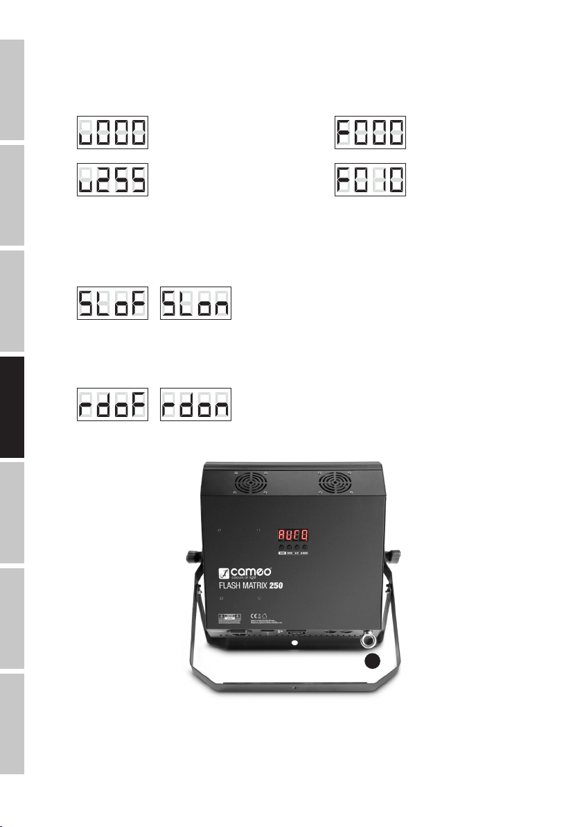
ESTROBO
Pulse varias veces el botón MODE hasta que en pantalla se muestre el valor de intensidad de v000 a v255 (valor xxx). Ajuste la intensidad
mediante los botones UP y DOWN (v000= oscurecimiento, v001= intensidad mínima, v255= intensidad máxima) y confirme con ENTER.
Pulse MODE una vez para ir a la opción de menú para ajustar la frecuencia de destellos del estrobo. En la pantalla se mostrará el valor
actualmente establecido. Con los botones UP y DOWN seleccione la velocidad de destello deseada (F000= frecuencia de destellos mínima,
F010= frecuencia de destellos máxima). Para confirmar y activar el estrobo, pulse ENTER.
ENGLISH
UP/DOWN -> MODE -> ENTERUP/DOWN
DEUTSCHFRANCAIS
MODO ESCLAVO
Pulse varias veces el botón MODE hasta que en pantalla se muestre «SLoF» o «SLon». Luego con los botones UP y DOWN seleccione la
opción «SLoF» para desactivar el modo Esclavo o «SLon» para activarlo, y confirme con ENTER. Si activa el modo Esclavo, conecte los equipos maestro y esclavo (del mismo modelo) con un cable DMX y active en el equipo maestro uno de los modos Autónomo. Ahora el equipo
esclavo estará sincronizado con el equipo maestro.
GIRAR LA PANTALLA 180°
Pulse varias veces el botón MODE hasta que en pantalla se muestre «rdoF» o «rdon». Ahora con los botones UP y DOWN seleccione la
opción «rdoF» para dejar la pantalla sin girar o «rdon» para girar la pantalla, y confirme con ENTER.
-> ENTER
- -
-> ENTERUP/DOWN /
-> ENTERUP/DOWN /
ESPAÑOL
INSTALACIÓN Y MONTAJE
ITALIANO POLSKIDMX
A
Gracias al soporte doble integrado, el foco se puede instalar perfectamente sobre una superficie plana. Para montarlo en trusses, utilice una
abrazadera adecuada (no suministrada). Para mayor seguridad, asegure el equipo introduciendo un cable de seguridad apropiado a través
de la argolla prevista para tal efecto(A). Nota importante: El montaje suspendido solo puede realizarse por personal experimentado.
28
Page 29

TECNOLOGÍA DMX
DMX-512
DMX (Digital Multiplex) is the designation for a universal transmission protocol for
communications between corresponding devices and controllers. A DMX controller sends
DMX data to the connected DMX device(s). The DMX data is always transmitted as a serial
data stream that is forwarded from one connected device to the next via the "DMX IN" and
"DMX OUT" connectors (XLR plug-type connectors) that are found on every DMX-capable
device, provided the maximum number of devices does not exceed 32 units. The last device
in the chain needs to be equipped with a terminator (terminating resistor).
DMX CONNECTION
DMX is the common "language" via which a very wide range of types and models of equipment from various manufacturers can
be connected with one another and controlled via a central controller, provided that all of the devices and the controller are DMX
compatible. For optimum data transmission, it is necessary to keep the connecting cables between the individual devices as short as
possible. The order in which the devices are integrated in the DMX network has no influence on the addresses. Thus the device with
the DMX address 1 can be located at any position in the (serial) DMX chain: at the beginning, at the end or somewhere in the middle.
If the DMX address 1 is assigned to a device, the controller "knows" that it should send all data allocated to address 1 to this device
regardless of its position in the DMX network.
SERIAL CONNECTION OF MULTIPLE LIGHTS
1. Connect the male XLR connector (3-pin or 5-pin) of the DMX cable to the DMX output (female XLR socket) of the first DMX device
(e.g. DMX-Controller).
2. Connect the female 3-pin XLR connector of the DMX cable connected to the first projector to the DMX input (male 3-pin socket)
of the next DMX device. In the same way, connect the DMX output of this device to the DMX input of the next device and repeat until
all devices have been connected. Please note that as a rule, DMX devices are connected in series and connections cannot be shared
without active splitters. The maximum number of DMX devices in a DMX chain should not exceed 32 units.
The Adam Hall 3 STAR, 4 STAR, and 5 STAR product ranges include an extensive selection of suitable cables.
DMX CABLES
When fabricating your own cables, always observe the illustrations on this page. Never connect the shielding of the cable to the ground
contact of the plug, and always make certain that the shielding does not come into contact with the housing of the XLR plug. If the shielding
is connected to the ground, this can lead to short-circuiting and system malfunctions.
Pin Assignment
DMX cable with 3-pin XLR connectors: DMX cable with 5-pin XLR connectors (pin 4 and 5 are not used):
1
3
2
Shield
1
3
2
5
4
3
2
1
Shield
DMX TERMINATORS (TERMINATING RESISTORS)
To prevent system errors, the last device in a DMX chain needs to be equipped with a terminating resistor (120 ohm, 1/4 Watt).
3-pin XLR connector with a terminating resistor: K3DMXT3
5-pin XLR connector with a terminating resistor: K3DMXT5
Pin Assignment
3-pin XLR connector: 5-pin XLR connector:
1
3
2
5
4
3
2
1
5
4
3
2
1
ENGLISH
DEUTSCH
FRANCAIS
ESPAÑOL
POLSKI
ITALIANO
DMX ADAPTER
The combination of DMX devices with 3-pin connectors and DMX devices with 5-pin connectors in a DMX chain is possible with suitable
adapters.
Pin Assignment
DMX Adapter 5-pin XLR male to 3-pin XLR female: K3DGF0020
Pins 4 and 5 are not used.
Pin Assignment
DMX Adapter 3-pin XLR male to 5-pin XLR female: K3DHM0020
Pins 4 and 5 are not used.
DMX
29
Page 30

CARACTERÍSTICAS TÉCNICAS
Nombre del modelo: CLFM250
Tipo de producto: Matriz de 3 efectos en 1
Tipo: Estrobo, chaser y cegadora LED
ENGLISH
Colores de LED: Blanco frío
Número de LED: 25
Tipo de LED: 6 W
Ángulo de haz: 50°
Ángulo de campo: 74°
Entrada DMX: XLR macho de 3 pines
Salida DMX: XLR hembra de 3 pines
Modos DMX: 1canales, 2canales, 3canales, 5canales, 9canales, 25canales, 30canales
DEUTSCHFRANCAIS
Funciones DMX: Atenuador maestro, atenuador 1-25, programas automáticos 1-11, estrobo (>30Hz),
Modos Autónomo: Estrobo, programas automáticos 1-11, control por sonido, modo Maestro/Esclavo
Control: DMX512
Controles: Mode, Enter, Up, Down, interruptor de encendido/apagado
Indicadores: Pantalla LED
Alimentación eléctrica: 100 - 240 VAC, 50/60 Hz
Consumo: 125 W
Iluminancia a 1 metro: 3730 lux
Flujo luminoso: 9216 lm
Conexión de alimentación eléctrica: IEC de entrada y salida
Fusible: T1,6AL / 250V (5 × 20 mm)
Temperatura operativa: 0 a 40 °C
Humedad relativa: < 85%, sin condensación
ESPAÑOL
Material de la carcasa: Metal, ABS
Color de la carcasa: Negro
Refrigeración: Ventilador silencioso
Dimensiones (An x Al x F, sin soporte de
montaje):
Peso: 4 kg
Otras características: Cable eléctrico y soporte de montaje suministrados
frecuencia de destellos, control por sonido
305 × 310 × 105 mm
DECLARACIÓN DEL FABRICANTE
GARANTÍA DEL FABRICANTE Y LIMITACIÓN DE RESPONSABILIDAD
Consulte nuestras condiciones de garantía y limitaciones de responsabilidad en: http://www.adamhall.com/media/shop/downloads/documents/manufacturersdeclarations.pdf. En caso de necesitar servicio técnico, póngase en contacto con Adam Hall GmbH, Daimlerstraße 9,
61267 Neu Anspach (Alemania); correo electrónico Info@adamhall.com; +49 (0)6081 / 9419-0.
ITALIANO POLSKIDMX
ELIMINACIÓN CORRECTA DE ESTE PRODUCTO
(Aplicable en la Unión Europea y en los países europeos que dispongan de un sistema de recogida selectiva) El símbolo que aparece
sobre el producto o en la documentación adjunta indica que al final de la vida útil del equipo, no deberá desecharlo con los demás
residuos domésticos, con el fin de evitar posibles efectos negativos en el medio ambiente y en la salud humana debidos al vertido
incontrolado de desechos. La recogida selectiva ayuda a su posterior reciclaje y fomenta la reutilización sostenible de los componentes de
este equipo. Si es un particular, póngase en contacto con el distribuidor donde adquirió este producto, o con el ayuntamiento, para
informarse sobre el reciclaje adecuado de este equipo. Si es una empresa, póngase en contacto con su proveedor para informarse sobre los
términos y condiciones de su contrato de compra-venta. Este producto no debe mezclarse con otros residuos industriales.
30
Page 31

POLSKI
Gratulujemy wyboru!
To urządzenie zostało zaprojektowane i wyprodukowane przy zastosowaniu najwyższych kryteriów jakościowych w celu zapewnienia
wieloletniej bezawaryjnej eksploatacji. Proszę starannie przeczytać niniejszą instrukcję obsługi, aby móc jak najszybciej zacząć użytkować
ten produkt marki Cameo Light. Więcej informacji na temat Cameo Light znajdą Państwo na naszej stronie internetowej pod adresem
WWW.CAMEOLIGHT.COM.
ŚRODKI OSTROŻNOŚCI
1. Należy dokładnie przeczytać niniejszą instrukcję.
2. Wszystkie informacje i instrukcje przechowywać w bezpiecznym miejscu.
3. Należy przestrzegać zaleceń.
4. Należy przestrzegać wszystkich wskazówek ostrzegawczych. Nie wolno usuwać wskazówek bezpieczeństwa ani innych informacji
znajdujących się na urządzeniu.
5. Używać urządzenia wyłącznie w sposób zgodny z jego przeznaczeniem.
6. Stosować wyłącznie stabilne i pasujące statywy, ew. elementy mocujące (w przypadku instalacji stałych). Należy zadbać o prawidłową
instalację uchwytów ściennych i ich odpowiednie zabezpieczenie. Zapewnić bezpieczną instalację urządzenia i upewnić się, że urządzenie
nie spadnie.
7. Podczas instalacji przestrzegać obowiązujących w danym kraju przepisów bezpieczeństwa.
8. Urządzenie instalować i eksploatować z dala od grzejników, zasobników ciepła, pieców i innych źródeł ciepła. Zadbać o zainstalowanie urządzenia w
taki sposób, aby zawsze było ono wystarczająco chłodzone i nie mogło ulec przegrzaniu.
9. Nie umieszczać na urządzeniu źródeł zapłonu, takich jak np. palące się świece.
10. Nie wolno blokować szczelin wentylacyjnych.
11. Urządzenie zostało zaprojektowane wyłącznie do użytku w pomieszczeniach. Nie używać urządzenia w bezpośrednim sąsiedztwie wody
(nie dotyczy specjalnych urządzeń do stosowania na zewnątrz – w takim przypadku należy przestrzegać podanych poniżej wskazówek
specjalnych). Urządzenie nie może mieć kontaktu z palnymi materiałami, płynami ani gazami.
12. Zabezpieczyć urządzenie przed wniknięciem kapiącej lub pryskającej wody. Nie wolno stawiać na urządzeniu pojemników napełnionych
płynami, takich jak wazony czy naczynia z piciem.
13. Należy zadbać o to, aby do urządzenia nie wpadały żadne przedmioty.
14. Urządzenie można eksploatować tylko przy użyciu akcesoriów zalecanych i przewidzianych przez producenta.
15. Nie otwierać urządzenia ani nie dokonywać w nim zmian.
16. Po podłączeniu urządzenia sprawdzić wszystkie ciągi kablowe, aby zapobiec szkodom lub wypadkom np. w wyniku potknięcia.
17. Podczas transportu zadbać o to, aby urządzenie nie upadło, gdyż może to spowodować uszkodzenie mienia i obrażenia ciała.
18. Jeśli urządzenie nie działa prawidłowo, do jego wnętrza dostały się płyny lub przedmioty lub jeśli urządzenie zostało uszkodzone w inny
sposób, należy je natychmiast wyłączyć i odłączyć od gniazda sieciowego (jeśli urządzenie jest aktywne). Naprawę takiego urządzenia może
wykonać tylko autoryzowany personel specjalistyczny.
19. Do czyszczenia urządzenia stosować suchą ściereczkę.
20. Przestrzegać obowiązujących w danym kraju przepisów dotyczących usuwania odpadów. Podczas utylizacji opakowania oddzielić
tworzywo sztuczne od papieru i tektury.
21. Worki z tworzywa sztucznego należy przechowywać w miejscu niedostępnym dla dzieci.
DOTYCZY URZĄDZEŃ Z ZASILANIEM SIECIOWYM:
22. UWAGA: jeśli kabel sieciowy urządzenia jest wyposażony w zestyk ochronny, należy go podłączyć do gniazda z przewodem uziemiającym. Nigdy nie wolno dezaktywować przewodu uziemiającego kabla sieciowego.
23. Nie włączać urządzenia bezpośrednio po narażeniu go na silne wahania temperatury (np. po transporcie). Wilgoć i skropliny mogą uszkodzić
urządzenie. Włączyć urządzenie dopiero wtedy, gdy osiągnie temperaturę pokojową.
24. Przed podłączeniem urządzenia do gniazda elektrycznego należy sprawdzić, czy napięcie i częstotliwość sieci elektrycznej odpowiada wartościom podanym na urządzeniu. Jeśli urządzenie jest wyposażone w przełącznik napięcia, należy podłączyć je do gniazda tylko
wówczas, gdy wartości urządzenia odpowiadają wartościom sieci elektrycznej. Jeśli dołączony kabel sieciowy lub dołączony adapter
sieciowy nie pasuje do gniazda elektrycznego, należy skontaktować się z elektrykiem.
25. Nie stawać na kablu sieciowym. Należy zadbać o to, aby kable przewodzące napięcie nie były zagięte przy gnieździe sieciowym, przy
adapterze sieciowym ani przy gnieździe urządzenia.
26. Przy podłączaniu urządzenia zawsze należy zadbać o to, aby kabel sieciowy lub adapter sieciowy był zawsze łatwo dostępny. Odłączyć
urządzenie od źródła zasilania, gdy nie jest ono używane lub gdy ma zostać poddane czyszczeniu. Zawsze należy wyjmować kabel sieciowy
i adapter sieciowy z gniazda, chwytając za wtyczkę lub adapter, a nie za kabel. Nigdy nie dotykać kabla sieciowego i adaptera sieciowego
mokrymi dłońmi.
9. W miarę możliwości nie włączać i wyłączać urządzenia w krótkich odstępach czasu, gdyż może to mieć negatywny wpływ na jego
żywotność.
28. WAŻNA INFORMACJA: bezpieczniki należy wymieniać wyłącznie na bezpieczniki tego samego typu i o takich samych wartościach. Jeśli bezpiecznik
stale się przepala, należy skontaktować się z autoryzowanym centrum serwisowym.
29. Aby całkowicie odłączyć urządzenie od sieci, należy wyjąć kabel sieciowy lub adapter sieciowy z gniazda.
30. Jeśli urządzenie jest wyposażone w przyłącze sieciowe Volex, konieczne jest odblokowanie odpowiedniej wtyczki urządzenia Volex,
zanim będzie możliwe jej odłączenie. Oznacza to także, iż w wyniku pociągnięcia za kabel urządzenie może się przesunąć i spaść, co może
spowodować obrażenia ciała i/lub inne szkody, dlatego ważne jest, aby przewody były odpowiednio poprowadzone.
31. W przypadku zagrożenia uderzeniem pioruna lub jeśli urządzenie przez dłuższy czas nie jest używane, należy wyjąć kabel sieciowy i
adapter sieciowy z gniazda.
ENGLISH
DEUTSCH
FRANCAIS
ESPAÑOL
POLSKI
ITALIANO
DMX
31
Page 32

32. Instalacja urządzenia powinna odbywać się, gdy urządzenie nie jest podłączone do źródła zasilania (należy wyjąć wtyczkę z gniazda).
33. Kurz i inne osady wewnątrz urządzenia mogą je uszkodzić. W zależności od warunków otoczenia (kurz, nikotyna, opary itp.) urządzenie
powinno być konserwowane lub czyszczone przez wykwalifikowanego specjalistę (usługa nieobjęta gwarancją), aby zapobiec przegrzaniu i
nieprawidłowemu działaniu.
34: Odstęp od materiałów łatwopalnych musi wynosić co najmniej 0,5 m.
35. Powierzchnia przekroju poprzecznego przewodów zasilających większą liczbę urządzeń musi wynosić co najmniej 1,5 mm². W krajach
ENGLISH
Unii Europejskiej przewody muszą spełniać wymagania normy H05VV-F lub podobne wytyczne. Adam Hall oferuje odpowiednie przewody.
Używając tych przewodów można podłączyć większą liczbę urządzeń przez złącze Power out i Power in kolejnego urządzenia. Należy upewnić się, że całkowity pobór mocy wszystkich podłączonych urządzeń nie przekracza wartości podanej w amperach na urządzeniu. Należy
dopilnować, aby kable łączące poszczególne urządzenia były możliwie jak najkrótsze.
UWAGA:
Nigdy nie zdejmować pokrywy, gdyż grozi to porażeniem prądem. We wnętrzu urządzenia nie ma
żadnych części, które mogłyby zostać naprawione bądź poddane czynnościom konserwacyjnym przez
użytkownika. Czynności konserwacyjne i naprawy może przeprowadzać wyłącznie wykwalifikowany
DEUTSCHFRANCAIS
Trójkąt równoboczny z symbolem błyskawicy sygnalizuje nieizolowane, niebezpieczne napięcie we wnętrzu urządzenia, które
może spowodować porażenie prądem.
Trójkąt równoboczny z wykrzyknikiem oznacza ważne wskazówki dotyczące obsługi i konserwacji.
Ostrzeżenie! Ten symbol ostrzega przed gorącymi powierzchniami. Podczas użytkowania niektóre elementy mogą się nagrzać.
Urządzenie można dotykać lub transportować dopiero po jego ostygnięciu (po odczekaniu co najmniej 10 minut).
OSTROŻNIE! WAŻNE WSKAZÓWKI DOTYCZĄCE PRODUKTÓW OŚWIETLENIOWYCH!
1. Produkt przeznaczony jest do zastosowań profesjonalnych podczas organizacji imprez i nie nadaje się do oświetlania pomieszczeń w
gospodarstwie domowym.
2. Nigdy nie spoglądać bezpośrednio w stronę promienia świetlnego, nawet przez krótką chwilę.
3. Nigdy nie spoglądać w stronę promienia świetlnego przy pomocy urządzeń optycznych, takich jak np. szkło powiększające.
4. Efekty stroboskopowe mogą wywołać ataki epilepsji u osób wrażliwych na pulsujące światło! Dlatego osoby chorujące na epilepsję
powinny unikać miejsc, w których stosowane są stroboskopy.
ESPAÑOL
personel serwisowy.
WPROWADZENIE
LED FLASH MATRIX 250 3IN1 FX – STROBE – CHASER – BLINDER
CLFM250
FUNKCJE STEROWANIA:
1-kanałowe, 2-kanałowe, 3-kanałowe, 5-kanałowe, 9-kanałowe, 25-kanałowe, 30-kanałowe sterowanie DMX
Tryb pracy Master/Slave
Funkcje Standalone
CECHY:
Efekt FX 3 w 1: Strobe, Chaser, Blinder, 25 diod LED High Power o mocy 6 W, stroboskop charakteryzujący się wysoką częstotliwością pracy
(>30 Hz), stroboskop z 25-strefowym efektem pościgu, wyświetlanie cyfr, liter i znaków, funkcja Single Pixel Control (sterowanie pojedynczymi pikselami), sterowanie DMX-512, programy Standalone, tryb pracy Sterowanie muzyką, cichy wentylator, napięcie robocze: 100–240 V
AC, pobór mocy: 125 W, statyw/pałąk montażowy w zestawie.
ITALIANO POLSKIDMX
32
Page 33

ZŁĄCZA, ELEMENTY OBSŁUGI I WSKAŹNIKI
ENGLISH
6
1
POWER IN
Gniazdo sieciowe IEC ze zintegrowaną podstawą bezpiecznika. W zestawie znajduje się odpowiedni kabel sieciowy. WAŻNA INFORMACJA: bezpiecznik należy wymieniać wyłącznie na bezpiecznik tego samego typu i o takich samych parametrach, zgodnie z nadrukiem na
urządzeniu. Jeżeli bezpiecznik stale się przepala, należy skontaktować się z autoryzowanym centrum serwisowym.
2
POWER
Włącznik/Wyłącznik dopływu zasilania do urządzenia.
3
POWER OUT
Wyjściowe gniazdo zasilania sieciowego IEC. Gniazdo służy do zasilania dodatkowych lamp PAR firmy CAMEO. Należy upewnić się, że
całkowity pobór mocy wszystkich podłączonych urządzeń nie przekracza wartości podanej w amperach (A) na urządzeniu.
4
DMX INPUT
3-stykowe, męskie gniazdo XLR do podłączenia urządzenia sterującego DMX (np. pulpitu DMX).
5
DMX OUTPUT
3-stykowe, żeńskie gniazdo XLR do przesyłania sygnału sterowania DMX.
6
OCZKO ZABEZPIECZAJĄCE
Montaż nad głową może być wykonywany wyłącznie przez odpowiednio przeszkolony personel. Lampę PAR należy przy tym zabezpieczyć
przed upadkiem za pomocą odpowiednich lin zabezpieczających.
5
4
3
7
2
9
1
DEUTSCH
FRANCAIS
ESPAÑOL
POLSKI
8
7
WYŚWIETLACZ LED
Czteroznakowy wyświetlacz LED pokazuje tryb pracy i inne informacje o systemie.
8
PRZYCISKI OBSŁUGI
MODE: wybór trybu pracy i opcji ustawień.
ENTER: potwierdzenie zmian wartości i wyboru programu.
UP i DOWN: zmiana wartości, np. szybkości programu i adresu DMX, oraz wybór programów.
9
MIC
Mikrofon do trybu pracy Sterowanie muzyką.
ITALIANO
DMX
33
Page 34

OBSŁUGA
Po prawidłowym podłączeniu lampy PAR do prądu i włączeniu jest ona gotowa do użycia i włączy się z poprzednio wybranym trybem pracy.
USTAWIANIE ADRESU STARTOWEGO DMX
Naciskać przycisk MODE, dopóki na wyświetlaczu nie pojawi się aktualnie ustawiony adres startowy DMX (A001–A512). Za pomocą
ENGLISH
przycisków UP i DOWN można ustawić wybrany adres startowy DMX (A001–A512). Potwierdzić ustawienie za pomocą przycisku ENTER.
Sterowanie synchroniczne kilkoma lampami PAR tego samego modelu za pomocą jednego urządzenia sterującego DMX (np. pulpitu DMX)
możliwe jest po ustawieniu w lampach PAR identycznego adresu startowego DMX i tego samego trybu pracy DMX oraz połączeniu ich
kablami DMX.
-> ENTERUP/DOWN –
DEUTSCHFRANCAIS
USTAWIANIE TRYBU PRACY DMX
Naciskać przycisk MODE, dopóki na wyświetlaczu nie pojawi się jeden z 7 dostępnych trybów pracy DMX (CH01, CH02, CH03, CH05, CH9,
CH25, CH30). Tryb pracy DMX można wybrać za pomocą przycisków UP i DOWN. Potwierdzić ustawienie za pomocą przycisku ENTER.
Tabele z przyporządkowaniem kanałów dla różnych trybów DMX podano w rozdziale STEROWANIE DMX niniejszej instrukcji.
-> ENTERUP/DOWN –
STEROWANIE AUTOMATYCZNE
Wybrać jeden z 11 dostępnych programów automatycznych (SH01–SH11) oraz jego szybkość (SP01–SP10). Naciskać przycisk MODE,
dopóki na wyświetlaczu nie pojawi się jeden z programów automatycznych, wybrać program za pomocą przycisków UP i DOWN, a
następnie zatwierdzić przyciskiem ENTER. Nacisnąć jeden raz przycisk MODE, aby przejść do menu ustawień szybkości programu. Na
wyświetlaczu pojawi się jeden z 10 stopni szybkości. Za pomocą przycisków UP i DOWN można wybrać żądane ustawienie (SP01–SP10).
Potwierdzić ustawienie za pomocą przycisku ENTER.
ESPAÑOL
UP/DOWN -> MODE -> ENTERUP/DOWN
STEROWANIE MUZYKĄ
Aby móc sterować lampą PAR poprzez zintegrowany mikrofon (impulsy basowe), należy wybrać tryb pracy Sterowanie muzyką. Naciskać
przycisk MODE, dopóki na wyświetlaczu nie pojawi się napis „SnoF” lub „Snon”. Za pomocą przycisków UP i DOWN wybrać „SnoF” w celu
wyłączenia Sterowania muzyką lub „Snon” – w celu włączenia, a następnie zatwierdzić przyciskiem ENTER. Nacisnąć jeden raz przycisk
MODE, aby przejść do menu ustawień czułości mikrofonu. Na wyświetlaczu pojawi się aktualnie ustawiona wartość czułości lampy PAR na
dźwięki, którą można ustawić wedle życzenia za pomocą przycisków UP i DOWN (SE01 = minimalna czułość, SE99 = maksymalna czułość).
Zatwierdzić wprowadzone dane za pomocą przycisku ENTER.
ITALIANO POLSKIDMX
-> ENTER
– –
-> ENTERUP/DOWN -> MODE -> ENTERUP/DOWN
/ –
34
Page 35

STROBOSKOP
Naciskać przycisk MODE, dopóki na wyświetlaczu nie pojawi się wartość jasności od v000 do v255 (value xxx). Za pomocą przycisków UP
i DOWN wybrać żądaną jasność (v000 = zaciemnienie, v001 = minimalna jasność, v255 = maksymalna jasność) i zatwierdzić przyciskiem
ENTER. Nacisnąć jeden raz przycisk MODE, aby przejść do menu ustawień szybkości stroboskopu. Na wyświetlaczu pojawi się aktualnie
ustawiona wartość, którą można zmienić za pomocą przycisków UP i DOWN (F000 = minimalna szybkość, F010 = maksymalna szybkość).
Aby zatwierdzić i aktywować efekt stroboskopu, należy nacisnąć przycisk ENTER.
ENGLISH
UP/DOWN -> MODE -> ENTERUP/DOWN
TRYB SLAVE
Naciskać przycisk MODE, dopóki na wyświetlaczu nie pojawi się napis „SLoF” lub „SLon”. Za pomocą przycisków UP i DOWN wybrać
„SLoF” w celu wyłączenia trybu Slave lub „SLon” – w celu włączenia, a następnie zatwierdzić przyciskiem ENTER. Gdy aktywny jest tryb
Slave, należy połączyć jednostki Slave i Master (ten sam model) za pomocą kabla DMX i aktywować w jednostce Master jeden z trybów
Standalone. Jednostka Slave jest teraz podrzędna w stosunku do jednostki Master.
OBRÓT WYŚWIETLACZA O 180°
Naciskać przycisk MODE, dopóki na wyświetlaczu nie pojawi się napis „rdoF” lub „rdon”. Za pomocą przycisków UP i DOWN wybrać „rdoF”
w celu wyłączenia funkcji obracania wyświetlacza lub „rdon” – w celu włączenia, a następnie zatwierdzić przyciskiem ENTER.
-> ENTER
– –
-> ENTERUP/DOWN /
-> ENTERUP/DOWN /
USTAWIENIE I MONTAŻ
DEUTSCH
FRANCAIS
ESPAÑOL
POLSKI
A
Dzięki zintegrowanemu podwójnemu pałąkowi lampę PAR można ustawić w odpowiednim miejscu na równej płaszczyźnie. Do montażu na
trawersie służy specjalny zacisk do trawersu (nie znajduje się w zestawie). Należy zadbać o stabilne połączenie z pałąkiem montażowym i
zabezpieczyć lampę PAR odpowiednią liną zabezpieczającą, przewlekając ją przez uchwyt bezpieczeństwa (A). Ważna informacja: montaż
nad głową może być wykonywany wyłącznie przez odpowiednio przeszkolony personel.
ITALIANO
DMX
35
Page 36

TECHNIKA DMX
DMX-512
DMX (Digital Multiplex) to nazwa uniwersalnego protokołu transmisji do komunikacji
między odpowiednimi urządzeniami a kontrolerami. Kontroler DMX wysyła dane DMX
do podłączonych urządzeń DMX. Transmisja danych DMX następuje zawsze w formie
ENGLISH
szeregowego strumienia danych, który jest przekazywany z jednego urządzenia do
następnego przez znajdujące się w każdym urządzeniu obsługującym standard DMX złącza
„DMX IN” i „DMX OUT” (złącza wtykowe XLR), przy czym maksymalna liczba urządzeń nie
może przekraczać 32. Ostatnie urządzenie w łańcuchu należy wyposażyć w terminator.
ZŁĄCZE DMX:
DMX to wspólny „język”, za pomocą którego różne typy i modele urządzeń różnych producentów porozumiewają się ze sobą i
mogą być sterowane przy użyciu centralnego kontrolera, o ile wszystkie urządzenia i kontroler obsługują standard DMX. W celu
zapewnienia optymalnej transmisji danych wymagane jest, aby kable połączeniowe między poszczególnymi urządzeniami były
możliwie jak najkrótsze. Kolejność, w jakiej urządzenia są podłączone do sieci DMX, nie ma znaczenia dla adresowania. I tak
DEUTSCHFRANCAIS
urządzenie z adresem DMX 1 może znajdować się w dowolnym miejscu (szeregowego) łańcucha DMX – na początku, na końcu
lub gdzieś pośrodku. Po przydzieleniu urządzeniu adresu DMX 1, kontroler „wie”, że ma on wysyłać wszystkie dane przypisane do
adresu 1 do tego urządzenia, niezależnie od jego pozycji w sieci DMX.
POŁĄCZENIE SZEREGOWE KILKU REFLEKTORÓW
1. Męską wtyczkę XLR (3-stykową lub 5-stykową) kabla DMX podłączyć do wyjścia DMX (żeńskie gniazdo XLR) pierwszego
urządzenia DMX (np. kontrolera DMX).
2. Żeńską wtyczkę XLR kabla DMX podłączonego do pierwszego reflektora podłączyć do wejścia DMX (męskie gniazdo XLR)
następnego urządzenia DMX. Wyjście DMX tego urządzenia podłączyć w taki sam sposób do wejścia DMX następnego urządzenia
i tak dalej. Należy pamiętać, że urządzenia DMX podłącza się szeregowo, a połączeń nie można rozdzielać bez aktywnego
rozdzielacza. Maksymalna liczba urządzeń DMX w łańcuchu DMX nie może przekraczać 32.
Obszerny wybór odpowiednich kabli DMX oferują linie produktów Adam Hall 3 STAR, 4 STAR i 5 STAR.
KABEL DMX:
W przypadku stosowania własnych kabli należy bezwzględnie przestrzegać informacji podanych na ilustracjach na tej stronie. W żadnym
wypadku nie wolno łączyć osłony kabla z końcówką uziemiającą wtyczki. Należy także pamiętać, aby osłona nie miała kontaktu z obudową
wtyczki XLR. Jeśli osłona ma kontakt z uziemieniem, może dojść do awarii systemu.
Przyporządkowanie wtyczek:
ESPAÑOL
Kabel DMX z 3-stykowymi wtyczkami XLR: Kabel DMX z 5-stykowymi wtyczkami XLR (pin 4 i 5 są niepodłączone):
1
3
2
Shield
1
3
2
5
4
3
2
1
Shield
TERMINATOR DMX:
Aby zapobiec awariom systemu, należy wyposażyć ostatnie urządzenie w łańcuchu DMX w terminator (120 Ω, 1/4 W).
3-stykowa wtyczka XLR z terminatorem: K3DMXT3
5-stykowa wtyczka XLR z terminatorem: K3DMXT5
Przyporządkowanie wtyczek:
3-stykowa wtyczka XLR: 5-stykowa wtyczka XLR:
1
3
2
5
4
3
2
1
5
4
3
2
1
ITALIANO POLSKIDMX
ADAPTER DMX:
Możliwa jest także kombinacja urządzeń DMX z 3-stykowymi przyłączami i urządzeń DXM z 5-stykowymi przyłączami w jednym łańcuchu
DMX przy użyciu adapterów.
Przyporządkowanie wtyczek
Adapter DMX 5-stykowy XLR, męski, na 3-stykowy XLR, żeński: K3DGF0020
Pin 4 i 5 są niepodłączone.
Przyporządkowanie wtyczek
Adapter DMX 3-stykowy XLR, męski, na 5-stykowy XLR, żeński: K3DHM0020
Pin 4 i 5 są niepodłączone.
36
Page 37

DANE TECHNICZNE
Oznaczenie modelu: CLFM250
Rodzaj produktu: Efekt FX Matrix 3 w 1
Typ: Efekt LED Strobe – Chaser – Blinder
Spektrum kolorów diod LED Biały zimny
Liczba diod LED: 25
Typ diod LED: 6 W
Kąt wiązki światła (Beam): 50°
Kąt wiązki światła (Field): 74°
Wejście DMX: Męskie, 3-stykowe, XLR
Wyjście DMX: Żeńskie, 3-stykowe, XLR
Tryb DMX: 1-kanałowy, 2-kanałowy, 3-kanałowy, 5-kanałowy, 9-kanałowy, 25-kanałowy i
30-kanałowy
Funkcje DMX: Master Dimmer (ściemniacz główny), Dimmer (ściemniacz) 1-25, programy
automatyczne 1–11, stroboskop (30 Hz), czas błysku, Sterowanie muzyką
Funkcje Standalone: Stroboskop, programy automatyczne 1–11, Sterowanie muzyką, tryb Master/
Slave
Sterowanie: DMX512
Elementy obsługi: Mode, Enter, Up, Down, włącznik/wyłącznik
Wskaźniki: Wyświetlacz LED
Napięcie robocze: 100–240 V AC/50–60 Hz
Pobór mocy: 125 W
Natężenie oświetlenia (w odległości 1 m): 3730 lx
Strumień świetlny: 9216 lm
Złącze zasilania: Wejście i wyjście IEC
Bezpiecznik: T1,6AL/250 V (5 x 20 mm)
Temperatura otoczenia (w trakcie pracy): 0°C–40°C
Względna wilgotność powietrza: < 85%, bez kondensacji
Materiał obudowy: Metal, ABS
Kolor obudowy: Czarny
Chłodzenie obudowy: Cichy wentylator
Wymiary (szer. x wys. x gł., bez pałąka montażowego): 305 x 310 x 105 mm
Waga: 4 kg
Pozostałe cechy: kabel zasilający i uchwyt montażowy w zestawie
ENGLISH
DEUTSCH
FRANCAIS
ESPAÑOL
POLSKI
DEKLARACJE PRODUCENTA
GWARANCJA PRODUCENTA I OGRANICZENIE ODPOWIEDZIALNOŚCI
Nasze aktualne warunki gwarancji i informacje dotyczące ograniczenia odpowiedzialności znajdą Państwo na stronie: http://www.adamhall.
com/media/shop/downloads/documents/manufacturersdeclarations.pdf. W razie konieczności skorzystania z serwisu proszę skontaktować
się z firmą Adam Hall GmbH, Daimlerstraße 9, 61267 Neu Anspach / e-mail Info@adamhall.com / +49 (0)6081 / 9419-0.
PRAWIDŁOWA UTYLIZACJA NINIEJSZEGO PRODUKTU
(Obowiązuje w Unii Europejskiej i innych krajach europejskich stosujących system sortowania odpadów) Niniejszy symbol na produk-
cie lub związanych z nim dokumentach wskazuje, iż urządzenie po zakończeniu okresu użytkowania nie może być utylizowane razem
ze standardowymi odpadami domowymi, aby uniknąć szkód w środowisku lub szkód na osobie powstałych w wyniku niekontrolowanego
usuwania odpadów. Niniejszy produkt należy utylizować oddzielnie od innych odpadów i przekazać do punktu recyklingu w celu ponownego
wykorzystania użytych w nim materiałów w ramach idei zrównoważonego rozwoju. Klienci prywatni otrzymują informacje w zakresie przyjaznych dla środowiska możliwości usuwania odpadów od sprzedawcy, u którego produkt został zakupiony, lub w odpowiednich placówkach
regionalnych. Użytkownicy będący przedsiębiorcami proszeni są o kontakt ze swoimi dostawcami i ewentualne sprawdzenie uzgodnionych
umownie warunków utylizacji urządzeń. Niniejszy produkt nie może być utylizowany razem z innymi odpadami przemysłowymi.
ITALIANO
DMX
37
Page 38

ITALIANO
Avete fatto la scelta giusta!
Questo dispositivo è stato sviluppato e prodotto in conformità con elevati standard qualitativi che ne garantiscono il regolare funzionamento
per molti anni. Leggete attentamente questo manuale d‘uso per utilizzare al meglio il vostro nuovo prodotto Cameo Light. Per maggiori
informazioni su Cameo Light consultare la nostra pagina Web WWW.CAMEOLIGHT.COM.
ENGLISH
MISURE PRECAUZIONALI
1. Lesen S1. Leggere attentamente il presente manuale di istruzioni.
2. Conservare tutte le indicazioni e le istruzioni in un luogo sicuro.
3. Seguire le istruzioni.
4. Rispettare tutte le avvertenze. Non rimuovere dal dispositivo le indicazioni sulla sicurezza o altre informazioni.
5. Utilizzare il dispositivo solo nei modi previsti dal manuale.
6. Utilizzare esclusivamente stativi e fissaggi stabili e adatti (per installazioni fisse). Verificare che i supporti a parete siano installati e fissati a
regola d‘arte. Verificare che il dispositivo sia installato in modo stabile e non possa cadere.
7. Durante l‘installazione, osservare le normative sulla sicurezza in vigore nel proprio Paese.
DEUTSCHFRANCAIS
8. Non installare né azionare il dispositivo in prossimità di radiatori, accumulatori termici, stufe o altre fonti di calore. Accertarsi che il dispositivo sia
sempre installato in modo che venga raffreddato a sufficienza e non possa surriscaldarsi.
9. Non appoggiare sul dispositivo fonti di combustione, quali candele accese.
10. Le fessure di areazione non devono essere bloccate.
11. Il dispositivo è destinato all‘impiego esclusivamente in ambienti chiusi; non deve essere utilizzato nelle immediate vicinanze di acqua
(questo punto non interessa i dispositivi specifici per l‘esterno, per i quali valgono le indicazioni speciali riportate di seguito). Non portare
mai il dispositivo a contatto con materiali, liquidi o gas infiammabili.
12. Accertarsi che all‘interno del dispositivo non possa penetrare acqua per gocciolamento o spruzzo. Non collocare sul dispositivo oggetti
contenenti liquidi, quali vasi, tazze o bicchieri.
13. Assicurarsi che non sia possibile la caduta di oggetti nel dispositivo.
14. Azionare il dispositivo esclusivamente con gli accessori appositamente consigliati e previsti dal produttore.
15. Non aprire né modificare il dispositivo.
16. Una volta collegato il dispositivo, verificare tutti i cavi per evitare danni o incidenti, ad esempio per inciampo.
17. Durante il trasporto, assicurarsi che il dispositivo non possa cadere e causare possibili danni a cose e/o persone.
18. Se il dispositivo non funzionasse più correttamente, vi fosse caduto sopra del liquido o un oggetto o fosse stato danneggiato in altro
modo, spegnerlo immediatamente e staccare la spina (se si tratta di un dispositivo attivo). La riparazione del dispositivo deve essere affidata
esclusivamente a personale qualificato autorizzato.
19. Per la pulizia del dispositivo utilizzare un panno pulito.
20. Rispettare le leggi sullo smaltimento in vigore nel Paese di installazione. Al momento di smaltire l‘imballo, separare la plastica dalla
ESPAÑOL
carta e dal cartone.
21. I sacchetti di plastica devono essere tenuti lontani dalla portata dei bambini.
DISPOSITIVI CON ALLACCIAMENTO DI RETE:
22. ATTENZIONE: se il cavo di rete è dotato di contatto di protezione, deve essere collegato a una presa di rete con messa a terra. Non
disattivare mai la connessione di messa a terra di un cavo di rete.
23. Non accendere il dispositivo subito dopo essere stato sottoposto a forti variazioni di temperatura (ad esempio dopo il trasporto). Umidità
e condensa potrebbero danneggiare il dispositivo. Accendere il dispositivo solo dopo che ha raggiunto la temperatura ambiente.
24. Prima di collegare il dispositivo alla presa, controllare innanzitutto se la tensione e la frequenza della rete elettrica coincidono con i
valori indicati sul dispositivo stesso. Nel caso di dispositivo munito di selettore di tensione, collegarlo alla presa unicamente se i valori del
dispositivo coincidono con quelli della rete elettrica. Se il cavo di rete o l‘adattatore di rete forniti in dotazione non sono compatibili con la
presa, rivolgersi a un elettricista.
25. Non calpestare il cavo di rete. Accertarsi che i cavi sotto tensione, in particolare della presa di rete o dell‘adattatore di rete, non vengano
pizzicati.
26. Durante il cablaggio del dispositivo, verificare sempre che il cavo di rete e l‘adattatore di rete siano costantemente accessibili. Staccare
sempre il dispositivo dall‘alimentazione di rete quando non è utilizzato o durante la pulizia. Per staccare dalla presa il cavo di rete e l‘adattatore di rete, tirare sempre dalla spina o dall‘adattatore e non dal cavo. Non toccare mai il cavo di alimentazione e l’alimentatore con le mani
umide.
27. Evitare per quanto possibile di accendere e spegnere velocemente il dispositivo per non pregiudicarne la durata.
ITALIANO POLSKIDMX
28. NOTA IMPORTANTE: Sostituire i fusibili esclusivamente con fusibili dello stesso tipo e valore. Se un fusibile continua a saltare, rivolgersi a
un centro di assistenza autorizzato.
29. Per staccare completamente il dispositivo dalla rete elettrica, rimuovere il cavo di rete o l‘adattatore di rete dalla presa.
30. Per staccare un dispositivo provvisto di presa Volex, è prima necessario sbloccare la relativa spina Volex del dispositivo stesso. Tirando il
cavo di rete, però, il dispositivo potrebbe spostarsi e cadere, provocando danni alle persone o di altro genere. Prestare quindi la più scrupolosa attenzione durante la posa dei cavi.
31. In caso di pericolo di caduta di fulmine, o se il dispositivo rimane inutilizzato a lungo, staccare sempre il cavo di rete e l‘adattatore di rete dalla
presa.
32. L‘installazione del dispositivo deve essere realizzata unicamente in assenza di tensione (staccare la spina dalla rete elettrica).
33. Polvere e depositi di altra natura all‘interno del dispositivo possono danneggiarlo. A seconda delle condizioni ambientali (polvere,
nicotina, nebbia ecc.) il dispositivo deve essere sottoposto a regolari interventi di manutenzione e pulizia da parte di personale specializzato
38
Page 39

(senza garanzia, interventi a carico del proprietario) per evitare surriscaldamento e malfunzionamenti.
34. La distanza dai materiali infiammabili deve essere di almeno 0,5 m
35. I cavi di rete utilizzati per l’alimentazione elettrica di più dispositivi devono avere una sezione di almeno 1,5mm². I cavi impiegati
nell’Unione Europea devono essere di tipo H05VV-F o simile. Adam Hall offre cavi idonei. Tali cavi consentono di collegare più dispositivi
dalla presa di uscita POWER OUT di un apparecchio alla presa POWER IN di un altro dispositivo. La potenza assorbita complessivamente da
tutti i dispositivi non deve superare il valore indicato (v.stampigliatura sul dispositivo stesso). Aver cura di mantenere i cavi di rete quanto
più possibile corti.
ATTENZIONE:
non togliere mai il coperchio di protezione perché sussiste il pericolo di scosse elettriche. L‘interno del dispositivo non contiene parti che possono essere riparate o sottoposte a manutenzione da
parte dell‘utente. Per gli interventi di manutenzione e di riparazione rivolgersi esclusivamente a
personale qualificato.
Il triangolo equilatero con il simbolo del lampo segnala la presenza di tensioni pericolose non isolate all‘interno dell‘apparecchio che possono causare scosse elettriche.
Il triangolo equilatero con punto esclamativo segnala la presenza di importanti informazioni relative all’uso e alla manutenzione.
Avvertimento! Questo simbolo indica superfici calde. Alcune parti della cassa potrebbero scaldarsi durante l‘impiego. Dopo aver
usato l‘apparecchiatura, lasciarla raffreddare per almeno 10 minuti prima di toccarla o trasportarla.
ATTENZIONE! INDICAZIONI IMPORTANTI RELATIVE AI PRODOTTI DI ILLUMINAZIONE!
1. Il prodotto è stato sviluppato per un uso professionale nel settore della tecnologia applicata a spettacoli e non è idoneo all‘impiego
nell‘illuminazione domestica.
2. Non fissare mai direttamente il fascio di luce, nemmeno per brevi istanti.
3. Non guardare mai il fascio di luce con dispositivi ottici quali le lenti d‘ingrandimento.
4. In alcuni casi, in persone sensibili gli effetti stroboscopici possono causare attacchi epilettici! Le persone affette da epilessia devono
perciò assolutamente evitare luoghi in cui vengono impiegati effetti stroboscopici.
INTRODUZIONE
MATRICE LED FLASH MATRIX 250 3 EFFETTI IN 1 - STROBO - CHASER - ACCECATORE
CLFM250
FUNZIONI DI COMANDO:
Controllo DMX a 1canale, 2canali, 3canali, 5canali, 9canali, 25canali, 30canali
Funzionamento master/slave
Funzioni standalone
CARATTERISTICHE
3 effetti in 1 - Strobo - Chaser - Accecatore, 25potenti LED da 6W, stroboscopio alta velocità (>30Hz), stroboscopio effetto chase con
25zone, rappresentazione di cifre, lettere e segni, controllo individuale di pixel, controllo DMX512, programmi standalone, comando tramite
musica, ventola silenziosa, tensione di esercizio 100-240V AC, potenza assorbita 125W, staffa di supporto/montaggio in dotazione.
ENGLISH
DEUTSCH
FRANCAIS
ESPAÑOL
POLSKI
ITALIANO
39
DMX
Page 40

CONNESSIONI, ELEMENTI DI COMANDO E DI VISUALIZZAZIONE
6
ENGLISH
1
POWER IN
Presa di rete IEC con portafusibili integrato. In dotazione viene fornito un cavo di alimentazione idoneo. NOTA IMPORTANTE: sostituire il fusibile unicamente con un fusibile dello stesso tipo e avente gli stessi valori serigrafati sul dispositivo. Se il fusibile continua a saltare, rivolgersi
a un centro di assistenza autorizzato.
2
POWER
DEUTSCHFRANCAIS
Interruttore di accensione/spegnimento del dispositivo.
3
POWER OUT
Presa di uscita di rete IEC. Serve per l'alimentazione elettrica di altri fari CAMEO. Assicurarsi che il totale della potenza assorbita di tutti i
dispositivi collegati all'apparecchio non superi il valore indicato in ampere (A).
4
DMX INPUT
Presa XLR maschio a 3poli per il collegamento di un apparecchio di controllo DMX (ad esempio mixer DMX).
5
DMX OUTPUT
Presa XLR femmina a 3poli per l'inoltro del segnale di controllo DMX.
6
OCCHIELLO DI SICUREZZA
Il montaggio sopratesta deve essere eseguito esclusivamente da personale qualificato che dovrà inoltre provvedere a fissare il faro con
ESPAÑOL
corde di sicurezza adatte per prevenirne la caduta.
5
4
3
7
2
9
1
8
7
DISPLAY LED
ITALIANO POLSKIDMX
Il display LED a quattro digiti mostra la modalità di funzionamento e altre informazioni di sistema.
8
TASTI DI COMANDO
MODE: consente di selezionare la modalità di funzionamento e le opzioni di impostazione.
ENTER: consente di confermare le modifiche dei valori e la selezione del programma.
UP e DOWN: consentono di modificare i valori, quali la velocità del programma e l'indirizzo DMX, e di selezionare i programmi.
9
MIC
Microfono per la modalità di funzionamento Comando tramite musica.
40
Page 41

UTILIZZO
Non appena il faro viene correttamente collegato alla rete elettrica e acceso, è pronto per l’uso e la modalità di funzionamento selezionata in
precedenza si attiva.
IMPOSTAZIONE DELL’INDIRIZZO DI AVVIO DMX
Premere il tasto MODE più volte fino a quando sul display non compare l’indirizzo DMX attualmente impostato (A001 - A512). Con i tasti UP
e DOWN è ora possibile impostare a piacere l’indirizzo di avvio DMX. Confermare l’inserimento premendo ENTER. Il controllo simultaneo
di più fari dello stesso modello (ad esempio mixer DMX) si ottiene impostando i fari su un indirizzo di avvio DMX identico e sulla stessa
modalità di funzionamento, collegandoli con i cavi DMX.
-> ENTERUP/DOWN -
IMPOSTAZIONE DELLA MODALITÀ DMX
Premere più volte il tasto MODE finché sul display non appare una delle 7modalità DMX disponibili (CH01, CH02, CH03, CH05, CH9, CH25,
CH30). La modalità DMX può essere ora impostata a piacimento con i tasti UP e DOWN. Confermare l’inserimento premendo ENTER. Le tabelle con l’assegnazione dei canali delle diverse modalità DMX sono riportate più avanti in questo manuale, alla sezione CONTROLLO DMX.
-> ENTERUP/DOWN -
COMANDO AUTOMATICO
Selezionare uno degli 11programmi auto (SH01 - SH11) e la relativa velocità di avanzamento (SP01 - SP10). Premere più volte il tasto
MODE finché sul display non appare uno dei programmi Auto, con i tasti UP e DOWN selezionare quindi un programma e confermare con
ENTER. Ora premere MODE una volta per accedere alla voce di menu che consente di impostare la velocità di avanzamento dei programmi.
Sul display viene visualizzato uno dei 10livelli di velocità; con i tasti UP e DOWN è possibile eseguire l’impostazione desiderata (SP01 SP10). Confermare l’inserimento premendo ENTER.
ENGLISH
DEUTSCH
FRANCAIS
ESPAÑOL
UP/DOWN -> MODE -> ENTERUP/DOWN
CONTROLLO TRAMITE MUSICA
Selezionare la modalità di funzionamento Controllo tramite musica per comandare il faro tramite il microfono integrato (impulsi gravi).
Premere più volte il tasto MODE fino a quando sul display non appare “SnoF” o “Snon”. Con i tasti UP e DOWN selezionare ora “SnoF” per
“Controllo tramite musica disattivato” e “Snon” per “Controllo tramite musica attivato”, quindi confermare con ENTER. Premere MODE
una volta per accedere alla voce di menu che consente di impostare la sensibilità del microfono. Sul display ora viene visualizzato il valore
attualmente impostato; con i tasti UP e DOWN è possibile impostare la sensibilità con cui si desidera che il faro reagisca ai rumori (SE01=
sensibilità minima, SE99= sensibilità massima). Confermare con ENTER.
-> ENTER
- -
-> ENTERUP/DOWN -> MODE -> ENTERUP/DOWN
/ -
POLSKI
ITALIANO
DMX
41
Page 42

STROBOSCOPIO
Premere più volte il tasto MODE fino a quando sul display non compare il valore della luminosità da v000 a v255 (valore xxx). Con i tasti UP
e DOWN impostare ora la luminosità desiderata (v000= blackout, v001= luminosità minima, v255= luminosità massima) e confermare l’inserimento con ENTER. Ora premere MODE una volta per accedere alla voce di menu che consente di impostare la velocità dello
stroboscopio. Sul display ora viene visualizzato il valore attualmente impostato e con i tasti UP e DOWN è possibile eseguire le modifiche
desiderate (F000= velocità minima, F010= velocità massima). Per confermare e attivare l’effetto stroboscopio, premere ENTER.
ENGLISH
UP/DOWN -> MODE -> ENTERUP/DOWN
DEUTSCHFRANCAIS
MODALITÀ SLAVE
Premere più volte il tasto MODE fino a quando sul display non appare “SLoF” o “SLon”. Con i tasti UP e DOWN selezionare ora “SLoF” per
“Modalità slave disattivata” e “SLon” per “Modalità slave attivata”, quindi confermare con ENTER. Se l’unità slave è attivata, collegare le
unità slave e master (stesso modello) utilizzando un cavo DMX e sull’unità master attivare una delle modalità standalone. Ora l’unità slave
segue l’unità master.
RUOTARE IL DISPLAY DI 180°
Premere più volte il tasto MODE fino a quando sul display non appare “rdoF” o “rdon”. Con i tasti UP e DOWN selezionare ora “rdoF” per
“Rotazione display disattivata” e “rdon” per “Rotazione display attivata”, quindi confermare con ENTER.
-> ENTER
- -
-> ENTERUP/DOWN /
-> ENTERUP/DOWN /
ESPAÑOL
INSTALLAZIONE E MONTAGGIO
ITALIANO POLSKIDMX
A
Grazie alla doppia staffa integrata, il faro può essere collocato in un punto adatto su una superficie piana. Per effettuare il montaggio su
traversa, utilizzare un morsetto adatto (non in dotazione). Aver cura che la staffa di montaggio sia fissata saldamente e assicurare il faro
facendo passare un cavo di sicurezza adatto dall’occhiello di sicurezza appositamente previsto (A). Nota importante: Il montaggio sopratesta
deve essere eseguito esclusivamente da personale qualificato
42
Page 43

TECNOLOGIA DMX
DMX512
DMX (Digital Multiplex) è la sigla di un protocollo di trasmissione universale per la
comunicazione tra dispositivi e controller. Un controller DMX invia dati DMX ai dispositivi
DMX collegati. I dati DMX vengono sempre trasmessi come flusso di dati seriale, che viene
inoltrato da un dispositivo collegato al successivo attraverso le connessioni (connettori
XLR) DMX IN e DMX OUT presenti per ogni dispositivo DMX compatibile, per un massimo di
32dispositivi. L'ultimo dispositivo della catena deve essere dotato di un connettore terminale
(terminatore).
COLLEGAMENTO DMX:
DMX è il linguaggio condiviso che consente l'accoppiamento tra diversi tipi di dispositivo e modelli di produttori differenti e il controllo
da parte di un controller centrale, a condizione che tutti i dispositivi e il controller siano DMX compatibili. Per una trasmissione
dei dati ottimale, il cavo che collega i singoli dispositivi deve essere il più corto possibile. L'ordine dei dispositivi nella rete DMX
non influisce sull'indirizzamento. Il dispositivo con indirizzo DMX1 può quindi trovarsi in una posizione qualsiasi della catena DMX
(seriale): all'inizio, alla fine o in qualsiasi punto al centro. Se a un dispositivo viene assegnato l'indirizzo DMX 1, il controller "sa" di
dover inviare a questo dispositivo tutti i dati attribuiti all'indirizzo 1, indipendentemente dalla sua posizione nella interconnessione
DMX.
ACCOPPIAMENTO SERIALE DI PIÙ PROIETTORI
1. Collegare il connettore XLR maschio (a 3 o 5poli) del cavo DMX con l'uscita DMX (presa XLR femmina) del primo dispositivo DMX
(ad esempio controller DMX).
2. Collegare il connettore XLR femmina del cavo DMX connesso al primo proiettore DMX con l'ingresso DMX (presa XLR maschio)
del successivo dispositivo DMX. Analogamente, collegare l'uscita DMX di questo dispositivo con l'ingresso DMX del dispositivo
seguente e così via. Tenere presente che in linea di principio i dispositivi DMX sono collegati in serie e i collegamenti non si possono
condividere senza uno splitter attivo. In una catena DMX i dispositivi DMX non possono essere più di 32.
Nelle linee di prodotti Adam Hall 3STAR, 4STAR e 5STAR è disponibile un'ampia scelta di cavi DMX.
CAVO DMX:
In caso di cavi di propria realizzazione, procedere secondo le figure di questa pagina. Non collegare mai la schermatura dei cavi con il
contatto di massa del connettore e assicurarsi che la schermatura non entri in contatto con l'involucro del connettore XLR. Il contatto di
massa della schermatura può generare guasti al sistema.
Configurazione dei connettori:
Cavo DMX con connettori XLR a 3poli: Cavo DMX con connettori XLR a 5poli (pin4 e 5 non assegnati):
1
3
2
Shield
1
3
2
5
4
3
2
1
Shield
CONNETTORE TERMINALE DMX (TERMINATORE):
Per evitare errori di sistema, l'ultimo dispositivo di una catena DMX deve essere dotato di una resistenza di terminazione (120ohm, 1/4W).
Connettore XLR a 3poli con resistenza di terminazione: K3DMXT3
Connettore XLR a 5poli con resistenza di terminazione: K3DMXT5
Configurazione dei connettori:
Connettore XLR a 3poli: Connettore XLR a 5poli:
1
3
2
5
4
3
2
1
5
4
3
2
1
ENGLISH
DEUTSCH
FRANCAIS
ESPAÑOL
POLSKI
ITALIANO
ADATTATORE DMX:
Se si utilizzano degli adattatori, in una catena DMX si possono anche combinare dispositivi DMX con collegamenti a 3poli e dispositivi DMX
con collegamenti a 5poli.
Configurazione dei connettori
Adattatore DMX XLR maschio 5poli a XLR femmina 3poli: K3DGF0020
Pin 4 e 5 non assegnati.
Configurazione dei connettori
Adattatore DMX XLR maschio 3poli a XLR femmina 5poli: K3DHM0020
Pin 4 e 5 non assegnati.
DMX
43
Page 44
DATI TECNICI
Nome del modello: CLFM250
Tipo di prodotto: Matrice 3 effetti in 1
Tipo: Strobo - Chaser - Accecatore LED
ENGLISH
Spettro cromatico LED: Bianco freddo
Numero di LED: 25
Tipo di LED: 6 W
Angolo di proiezione (angolo del fascio): 50°
Angolo di proiezione (angolo di campo): 74°
Ingresso DMX: XLR maschio a 3 poli
Uscita DMX: XLR femmina a 3 poli
Modalità DMX: 1canale, 2canali, 3canali, 5canali, 9canali, 25 canali, 30canali
DEUTSCHFRANCAIS
Funzioni DMX: Master dimmer, dimmer 1-25, programmi Auto 1-11, stroboscopio (>30Hz), durata
Funzioni standalone: Stroboscopio, programmi Auto 1-11, controllo tramite musica, funzionamento master/
Comando: DMX512
Elementi di comando: Mode, Enter, Up, Down, interruttore di accensione/spegnimento
Elementi di visualizzazione: Display LED
Tensione di esercizio: 100 - 240 V AC, 50/60Hz
Potenza assorbita: 125 W
Potenza di illuminazione (a 1 m): 3.730 lx
Flusso luminoso: 9.216 lm
Collegamento alimentazione elettrica: Presa IEC ingresso e uscita
Fusibile: T1,6AL / 250 V (5 x 20 mm)
Temperatura ambiente (in esercizio): 0 °C - 40 °C
ESPAÑOL
Umidità relativa dell'aria: < 85%, senza condensazione
Materiale cassa: Metallo, ABS
Colore cassa: Nero
Raffreddamento della cassa: Ventola silenziosa
Ingombro (L x H x P, senza staffa di montaggio): 305 x 310 x 105 mm
Peso: 4 kg
Altre caratteristiche: Cavo di alimentazione e staffa di montaggio in dotazione
flash, controllo tramite musica
slave
DICHIARAZIONI DEL PRODUTTORE
MANUFACTURER’S WARRANTY & LIMITATION OF LIABILITY
Le nostre attuali condizioni di garanzia e la limitazione di responsabilità sono consultabili alla pagina: http://www.adamhall.com/media/
shop/downloads/documents/manufacturersdeclarations.pdf. In caso di assistenza, rivolgersi a Adam Hall GmbH, Daimlerstraße 9, 61267
Neu Anspach / E-mail Info@adamhall.com / +49 (0)6081 / 9419-0.
ITALIANO POLSKIDMX
CORRETTO SMALTIMENTO DEL PRODOTTO
(In vigore nell‘Unione Europea e in altri Paesi europei in cui si attui la raccolta differenziata) Questo simbolo apposto sul prodotto o
sui relativi documenti indica che, per evitare danni all‘ambiente e alle persone causati da uno smaltimento incontrollato dei rifiuti,
alla fine del suo ciclo di vita l‘apparecchio non deve essere smaltito insieme ai normali rifiuti domestici. Il prodotto deve quindi essere
smaltito separatamente da altri rifiuti e riciclato nell‘ottica dell‘incentivazione di cicli economici sostenibili. I clienti privati possono richiedere
informazioni sulle possibilità di smaltimento ecosostenibile al rivenditore presso il quale è stato acquistato il prodotto o presso le autorità
regionali competenti. I clienti aziendali devono invece contattare il proprio fornitore e controllare le eventuali condizioni contrattuali inerenti
allo smaltimento degli apparecchi. Questo prodotto non deve essere smaltito assieme ad altri rifiuti industriali.
44
Page 45

DMX CONTROL / DMX STEUERUNG / PILOTAGE DMX / CONTROL DMX / STEROWANIE DMX /
CONTROLLO DMX
1-CH Mode
000 - 005 Auto Programs off
006 - 028 Auto Program 1
029 - 051 Auto Program 2
052 - 074 Auto Program 3
075 - 097 Auto Program 4
CH1 Auto Programs
2-CH Mode
CH1 Master Dimmer 000 - 255 Master Dimmer 0% - 100%
CH2 Strobe
098 - 120 Auto Program 5
121 - 143 Auto Program 6
144 - 166 Auto Program 7
167 - 189 Auto Program 8
190 - 212 Auto Program 9
213 - 235 Auto Program 10
236 - 255 Auto Program 11
000 - 005 Strobe open
006 - 010 Strobe closed
011 - 033 Puls Random, slow -> fast
034 - 056 Ramp up Random, slow -> fast
057 - 079 Ramp down Random, slow -> fast
080 - 102 Random Strobe Effect, slow fast
103 - 127 Strobe Break Effekt, 5s…..1s (Very Short Flash)
128 - 250 Strobe slow -> fast <1Hz - 30Hz
251 - 255 Strobe open
ENGLISH
DEUTSCH
FRANCAIS
ESPAÑOL
POLSKI
3-CH Mode
CH1 Master Dimmer 000 - 255 Master Dimmer 0% - 100%
000 - 005 Strobe open
006 - 010 Strobe closed
011 - 033 Puls Random, slow -> fast
034 - 056 Ramp up Random, slow -> fast
CH2 Strobe
CH3 Duration 000 - 255 Flash duration (0ms to 510ms)
057 - 079 Ramp down Random, slow -> fast
080 - 102 Random Strobe Effect, slow fast
103 - 127 Strobe Break Effekt, 5s…..1s (Very Short Flash)
128 - 250 Strobe slow -> fast <1Hz - 30Hz
251 - 255 Strobe open
ITALIANO
DMX
45
Page 46

5-CH Mode
CH1 Master Dimmer 000 - 255 Master Dimmer 0% - 100%
000 - 005 Strobe open
ENGLISH
CH2 Strobe
DEUTSCHFRANCAIS
CH3 Duration 000 - 255 Flash duration (0ms to 510ms)
CH4
Auto Programs
(override CH1-3)
ESPAÑOL
CH5 000 - 255 Auto Speed (slow to fast) / Sound Sensitivity
006 - 010 Strobe closed
011 - 033 Puls Random, slow -> fast
034 - 056 Ramp up Random, slow -> fast
057 - 079 Ramp down Random, slow -> fast
080 - 102 Random Strobe Effect, slow fast
103 - 127 Strobe Break Effekt, 5s…..1s (Very Short Flash)
128 - 250 Strobe slow -> fast <1Hz - 30Hz
251 - 255 Strobe open
000 - 005 Auto Programs off
006 - 023 Auto Program 1
024 - 041 Auto Program 2
042 - 089 Auto Program 3
090 - 107 Auto Program 4
108 - 125 Auto Program 5
126 - 143 Auto Program 6
144 - 161 Auto Program 7
162 - 179 Auto Program 8
180 - 197 Auto Program 9
198 - 215 Auto Program 10
216 - 233 Auto Program 11
234 - 255 Sound Mode
9-CH Mode
CH1 Dimmer 000 - 255 Master Dimmer 0-100%
000 - 005 Strobe open
006 - 010 Strobe closed
ITALIANO POLSKIDMX
CH2 Strobe
011 - 033 Puls Random, slow -> fast
034 - 056 Ramp up Random, slow -> fast
057 - 079 Ramp down Random, slow -> fast
080 - 102 Random Strobe Effect, slow fast
103 127 Strobe Break Effekt, 5s…..1s ( Very Short Flash)
128 - 250 Strobe slow -> fast <1Hz - 30Hz
250 - 255 Strobe open
46
Page 47

CH3 Selection Folder
Letters (Turning
Speed from CH 5,
CH4
Fading and Wake
over Channel 7)
000 - 005 off
006 - 131 Letters
132 - 255 Numbers & Symbols
000 - 004 A
005 - 009 B
010 - 014 C
015 - 019 D
020 - 024 E
025 - 029 F
030 - 034 G
035 - 039 H
040 - 044 I
045 - 049 J
050 - 054 K
055 - 059 L
060 - 064 M
065 - 069 N
070 - 074 O
075 - 079 P
080 - 084 Q
085 - 089 R
090 - 094 S
095 - 099 T
100 - 104 U
105 - 109 V
110 - 114 W
115 - 119 X
120 - 124 Y
125 - 129 Z
130 - 255 Empty
ENGLISH
DEUTSCH
FRANCAIS
ESPAÑOL
POLSKI
ITALIANO
47
DMX
Page 48

ENGLISH
DEUTSCHFRANCAIS
CH4
ESPAÑOL
ITALIANO POLSKIDMX
Numbers &
Symbols (Turning
Speed from CH 5,
Fading and Wake
over Channel 7)
000 - 004 0
005 - 009 1
010 - 014 2
015 - 019 3
020 - 024 4
025 - 029 5
030 - 034 6
035 - 039 7
040 - 044 8
045 - 049 9
050 - 054 +
055 - 059 -
060 - 064 :
065 - 069 %
070 - 074 !
075 - 079 ?
080 - 084 =
085 - 089 <
090 - 094 >
095 - 099 ^
100 - 104
105 - 109 [
110 - 114 ]
115 - 119 Arroiw top
120 - 124 Arrow right
125 - 129 Arrow left
130 - 134 Arrow bottom
135 - 139 Arrow top left
140 - 144 Arrow top right
145 - 149 Arrow bottom left
150 - 154 Arrow bottom right
155 - 159 All LEDs ON
160 - 255 Empty
˅
48
Page 49

CH5
CH6
CH7
CH8
CH9
Speed for: Letters,
Numbers
Pattern Transition
(Transition between
Pattern)
Effect Pattern
Fade/Wake
Invert / Swap
Pattern
Master Dimmer
Invert
000 - 005 Effect Pattern Speed Stop
006 - 047 Effect Pattern Pos. (0°,45°,90°135°,180°,225°,270°,315°)
048 - 069 Effect Pattern Speed Stop
070 - 101 Effect Pattern Speed, slow > fast, Top -> Bottom
102 - 133 Effect Pattern Speed, slow > fast, Bottom -> Top
134 - 165 Effect Pattern Speed, slow > fast, left -> right
166 - 197 Effect Pattern Speed, slow > fast, right -> left
198 - 229 Effect Pattern Speed Stop
230 - 255 Sound Trigger Speed Low > High
000 - 005
006 - 255 0s - 5s
000 - 005 off
006 - 127 Fade Effect Pattern less -> more
128 - 255 Wake Effect Pattern less -> more
000 - 005 off
006 - 084 Invert
085 - 163 Swap
164 - 255 Swap / Invert
000 - 255 Invert Dimmer 0-100% (Switch active and inactive LEDs)
off
ENGLISH
DEUTSCH
FRANCAIS
ESPAÑOL
49
POLSKI
ITALIANO
DMX
Page 50

25-CH Mode
CH1
CH2 000 - 255 Dimmer LED 2
CH3 000 - 255 Dimmer LED 3
ENGLISH
CH4 000 - 255 Dimmer LED 4
CH5 000 - 255 Dimmer LED 5
CH6 000 - 255 Dimmer LED 6
CH7 000 - 255 Dimmer LED 7
CH8 000 - 255 Dimmer LED 8
CH9 000 - 255 Dimmer LED 9
DEUTSCHFRANCAIS
CH10 000 - 255 Dimmer LED 10
CH11 000 - 255 Dimmer LED 11
CH12 000 - 255 Dimmer LED 12
CH13 000 - 255 Dimmer LED 13
CH14 000 - 255 Dimmer LED 14
CH15 000 - 255 Dimmer LED 15
CH16 000 - 255 Dimmer LED 16
CH17 000 - 255 Dimmer LED 17
CH18 000 - 255 Dimmer LED 18
CH19 000 - 255 Dimmer LED 19
CH20 000 - 255 Dimmer LED 20
CH21 000 - 255 Dimmer LED 21
ESPAÑOL
CH22 000 - 255 Dimmer LED 22
CH23 000 - 255 Dimmer LED 23
CH24 000 - 255 Dimmer LED 24
CH25 000 - 255 Dimmer LED 25
Light Control
000 - 255 Dimmer LED 1
ITALIANO POLSKIDMX
50
Page 51

30-CH Mode
CH1 Master Dimmer 000 - 255 Master Dimmer 0% - 100%
CH2 Strobe
CH3 Duration 000 - 255 Flash duration (0ms to 510ms)
CH4
CH5 000 - 255 Auto Speed (slow to fast) / Sound Sensitivity
Auto Programs
000 - 005 Strobe off
006 - 255 Strobe slow -> fast <1Hz - 30Hz
000 - 005 Auto Programs off
006 - 023 Auto Program 1
024 - 041 Auto Program 2
042 - 089 Auto Program 3
090 - 107 Auto Program 4
108 - 125 Auto Program 5
126 - 143 Auto Program 6
144 - 161 Auto Program 7
162 - 179 Auto Program 8
180 - 197 Auto Program 9
198 - 215 Auto Program 10
216 - 233 Auto Program 11
234 - 255 Sound Mode
ENGLISH
DEUTSCH
FRANCAIS
ESPAÑOL
51
POLSKI
ITALIANO
DMX
Page 52

CH6
CH7 000 - 255 Dimmer LED 2
CH8 000 - 255 Dimmer LED 3
CH9 000 - 255 Dimmer LED 4
ENGLISH
CH10 000 - 255 Dimmer LED 5
CH11 000 - 255 Dimmer LED 6
CH12 000 - 255 Dimmer LED 7
CH13 000 - 255 Dimmer LED 8
CH14 000 - 255 Dimmer LED 9
CH15 000 - 255 Dimmer LED 10
DEUTSCHFRANCAIS
CH16 000 - 255 Dimmer LED 11
CH17 000 - 255 Dimmer LED 12
CH18 000 - 255 Dimmer LED 13
CH19 000 - 255 Dimmer LED 14
CH20 000 - 255 Dimmer LED 15
CH21 000 - 255 Dimmer LED 16
CH22 000 - 255 Dimmer LED 17
CH23 000 - 255 Dimmer LED 18
CH24 000 - 255 Dimmer LED 19
CH25 000 - 255 Dimmer LED 20
CH26 000 - 255 Dimmer LED 21
CH27 000 - 255 Dimmer LED 22
ESPAÑOL
CH28 000 - 255 Dimmer LED 23
CH29 000 - 255 Dimmer LED 24
CH30 000 - 255 Dimmer LED 25
Light Control
000 - 255 Dimmer LED 1
ITALIANO POLSKIDMX
52
Page 53

Page 54

Page 55

Page 56

WWW.CAMEOLIGHT.COM
Adam Hall GmbH | Daimlerstrasse 9 | 61267 Neu-Anspach | Germany
Tel. +49(0)6081/9419-0 | Fax +49(0)6081/9419-1000
web : www.adamhall.com | e-mail : mail@adamhall.com
REV: 02
 Loading...