

Cameo F2 T, F2 D operation manual

USER´S MANUAL
BEDIENUNGSANLEITUNG
MANUEL D`UTILISATION
MANUAL DE USUARIO
INSTRUKCJA OBSŁUGI
MANUALE D‘ USO
F2 T
TUNGSTEN LED FRESNEL SPOT LIGHT
CLF2T
F2 D
DAYLIGHT LED FRESNEL SPOT LIGHT
CLF2D

CONTENTS / INHALTSVERZEICHNIS / CONTENU / CONTENIDO / TREŚĆ / CONTENUTO
ENGLISH
PREVENTIVE MEASURES 3-4
INTRODUCTION 4
CONNECTIONS, OPERATING AND DISPLAY ELEMENTS 5-6
OPERATION 6-9
INSTALLATION 10
INSTALLATION/REMOVAL OF BARN DOORS AND
FILTER FRAME 10
DMX TECHNOLOGY 11
TECHNICAL DATA 12
MANUFACTURER’S DECLARATIONS 13
DMX CONTROL 70-72
DEUTSCH
SICHERHEITSHINWEISE 14-15
EINFÜHRUNG 15
ANSCHLÜSSE, BEDIEN- UND ANZEIGEELEMENTE 16-17
BEDIENUNG 17-20
AUFSTELLUNG UND MONTAGE 21
FLÜGELBEGRENZER UND FILTERRAHMEN MONTIEREN /
DEMONTIEREN 21
DMX TECHNIK 22
TECHNISCHE DATEN 23
HERSTELLERERKLÄRUNGEN 24
DMX STEUERUNG 70-72
FRANCAIS
MESURES PRÉVENTIVES 25-26
INTRODUCTION 26-27
RACCORDEMENTS, ÉLÉMENTS DE COMMANDE
ET D’AFFICHAGE 27-28
MODE D’EMPLOI 28-31
INSTALLATION ET MONTAGE 32
MONTAGE/DÉMONTAGE DES VOLETS COUPE-FLUX
ET DU CADRE POUR FILTRE 32
TECHNOLOGIE DMX 33
CARACTÉRISTIQUES TECHNIQUES 34
DÉCLARATIONS DU FABRICANT 35
PILOTAGE DMX 70-72
ESPAÑOL
MEDIDAS DE SEGURIDAD 36-37
INTRODUCCIÓN 37-38
CONEXIONES, ELEMENTOS DE MANEJO Y ELEMENTOS
DE VISUALIZACIÓN 38-39
FUNCIONAMIENTO 39-42
INSTALACIÓN Y MONTAJE 43
MONTAJE Y DESMONTAJE DE LA VISERA Y
EL PORTAFILTROS 43
TECNOLOGÍA DMX 44
DATOS TÉCNICOS 45
DECLARACIONES DEL FABRICANTE 46
CONTROL DMX 70-72
POLSKI
ŚRODKI OSTROŻNOŚCI 47-48
WPROWADZENIE 48-49
GNIAZDA, ELEMENTY OBSŁUGI I WSKAŹNIKI 49-50
OBSŁUGA 50-53
USTAWIANIE I MONTAŻ 54
MONTAŻ/ DEMONTAŻ KLAP OGRANICZAJĄCYCH
POLE ŚWIECENIA ORAZ RAMKI FILTRA 54
TECHNIKA DMX 55
DANE TECHNICZNE 56
OŚWIADCZENIA PRODUCENTA 57
STEROWANIE DMX 70-72
ITALIANO
MISURE PRECAUZIONALI 58-59
INTRODUZIONE 59-60
RACCORDI, ELEMENTI DI COMANDO E DI VISUALIZZAZIONE 60-61
UTILIZZO 61-64
INSTALLAZIONE E MONTAGGIO 65
MONTAGGIO E SMONTAGGIO DEL DEFLETTORE AD
ALETTE E DEL TELAIO PORTAFILTRO 65
TECNOLOGIA DMX 66
DATI TECNICI 67
DICHIARAZIONI DEL PRODUTTORE 68
CONTROLLO DMX 70-72
ENGLISH
YOU‘VE MADE THE RIGHT CHOICE!
We have designed this product to operate reliably over many years. Please read this User‘s Manual carefully, so that you can begin making
optimum use of your Cameo Light product quickly. Learn more about Cameo Light on our website WWW.CAMEOLIGHT.COM.
PREVENTIVE MEASURES
1. Please read these instructions carefully.
2. Keep all information and instructions in a safe place.
3. Follow the instructions.
4. Observe all safety warnings. Never remove safety warnings or other information from the equipment.
5. Use the equipment only in the intended manner and for the intended purpose.
6. Use only sufficiently stable and compatible stands and/or mounts (for fixed installations). Make certain that wall mounts are properly installed and
secured. Make certain that the equipment is installed securely and cannot fall down.
7. During installation, observ e the applicable safety regulations for your country.
8. Never install and operate the equipment near radiators, heat registers, ovens or other sources of heat. Make certain that the equipment is
always installed so that is cooled sufficiently and cannot overheat.
9. Never place sources of ignition, e.g., burning candles, on the equipment.
10. Ventilation slits must not be blocked.
11. This appliance is designed exclusively for indoor use, do not use this equipment in the immediate vicinity of water (does not apply
to special outdoor equipment - in this case, observe the special instructions noted below). Do not expose this equipment to flammable
materials, fluids or gases.
12. Make certain that dripping or splashed water cannot enter the equipment. Do not place containers filled with liquids, such as vases or
drinking vessels, on the equipment.
13. Make certain that objects cannot fall into the device.
14. Use this equipment only with the accessories recommended and intended by the manufacturer.
15. Do not open or modify this equipment.
16. After connecting the equipment, check all cables in order to prevent damage or accidents, e.g., due to tripping hazards.
17. During transport, make certain that the equipment cannot fall down and possibly cause property damage and personal injuries.
18. If your equipment is no longer functioning properly, if fluids or objects have gotten inside the equipment or if it has been damaged in
anot her way, switch it off immediately and unplug it from the mains outlet (if it is a powered device). This equipment may only be repaired
by authorized, qualified personnel.
19. Clean the equipment using a dry cloth.
20. Comply with all applicable disposal laws in your country. During disposal of packaging, please separate plastic and paper/cardboard.
21. Plastic bags must be kept out of reach of children.
FOR EQUIPMENT THAT CONNECTS TO THE POWER MAINS:
22. CAUTION: If the power cord of the device is equipped with an earthing contact, then it must be connected to an outlet with a protective
ground. Never deactivate the protective ground of a power cord.
23. If the equipment has been exposed to strong fluctuations in temperature (for example, after transport), do not switch it on immediately.
Moisture and condensation could damage the equipment. Do not switch on the equipment until it has reached room temperature.
24. Before connecting the equipment to the power outlet, first verify that the mains voltage and frequency match the values specified on the
equipment. If the equipment has a voltage selection switch, connect the equipment to the power outlet only if the equipment values and the
mains power values match. If the included power cord or power adapter does not fit in your wall outlet, contact your electrician.
25. Do not step on the power cord. Make certain that the power cable does not become kinked, especially at the mains outlet and/or power
adapter and the equipment connector.
26. When connecting the equipment, make certain that the power cord or power adapter is always freely accessible. Always disconnect the
equipment from the power supply if the equipment is not in use or if you want to clean the equipment. Always unplug the power cord and
power adapter from the power outlet at the plug or adapter and not by pulling on the cord. Never touch the power cord and power adapter
with wet hands.
27. Whenever possible, avoid switching the equipment on and off in quick succession because otherwise this can shorten the useful life of
the equipment.
28. IMPORTANT INFORMATION: Replace fuses only with fuses of the same type and rating. If a fuse blows repeatedly, please contact an
authorised service centre.
29. To disconnect the equipment from the power mains completely, unplug the power cord or power adapter from the power outlet.
30. If your device is equipped with a Volex power connector, the mating Volex equipment connector must be unlocked before it can be removed. However, this also means that the equipment can slide and fall down if the power cable is pulled, which can lead to personal injuries
and/or other damage. For this reason, always be careful when laying cables.
31. Unplug the power cord and power adapter from the power outlet if there is a risk of a lightning strike or before extended periods of disuse.
32. The device must only be installed in a voltage-free condition (disconnect the mains plug from the mains).
33. Dust and other debris inside the unit may cause damage. The unit should be regularly serviced or cleaned (no guarantee) depending on
ambient conditions (dust etc., nicotine, fog) by qualified personnel to prevent overheating and malfunction.
34. Please keep a distance of at least 0.5 m to any combustible materials.
35. Power cables to power multiple devices must have a cross-section of at least 1.5 mm². Within the EU, the cables must correspond to
H05VV-F, or similar. Suitable cables are offered by Adam Hall. With these cables, you can connect multiple devices via the power OUT connection to the power IN connection of an additional device. Make sure that the total current consumption of all connected devices does not
exceed the specified value on all connected devices (label on the device). Make sure to keep power cable connections as short as possible.
ENGLISH
DEUTSCHFRANCAIS
ESPAÑOL
ITALIANO POLSKI
DMX
3
DEUTSCHENGLISH
FRANCAIS
CAUTION:
To reduce the risk of electric shock, do not remove cover (or back). There are no user serviceable parts
inside. Maintenance and repairs should be exclusively carried out by qualified service personnel.
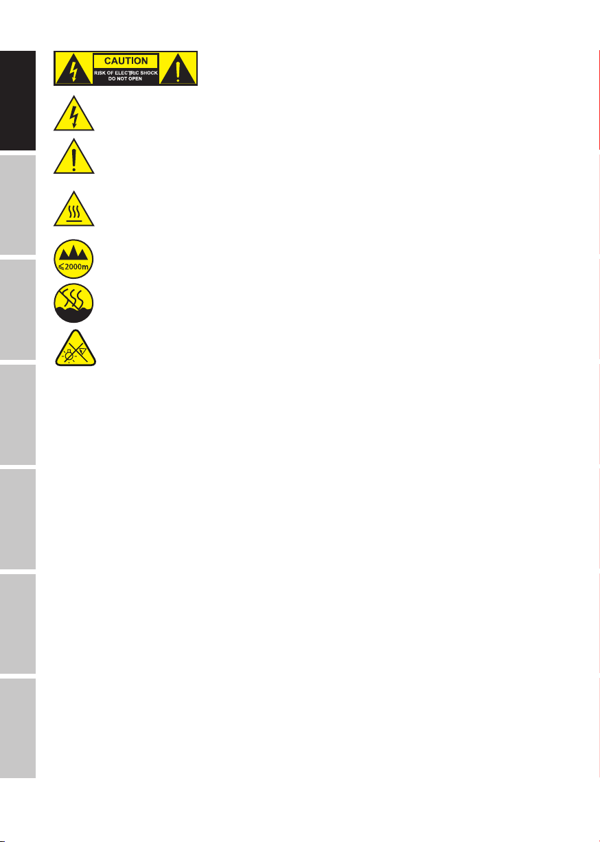
The warning triangle with lightning symbol indicates dangerous uninsulated voltage inside the unit, which may cause an
electrical shock.
The warning triangle with exclamation mark indicates important operating and maintenance instructions.
The housing surface of the spotlight can heat up to temperatures as high as 70 °C in regular use. Ensure that it is not possible
to come into contact with the housing unintentionally. Always allow sufficient time for the lamp to cool down before
dismantling, carrying out maintenance work or charging etc.
Warning! This device is designed for use below 2000 metres in altitude.
Warning! This product is not intended for use in tropical climates.
CAUTION! IMPORTANT INFORMATION ABOUT LIGHTING PRODUCTS!
ESPAÑOL
1. The product has been developed for professional use in the field of event technology and is not suitable as household lighting.
2. Do not stare, even temporarily, directly into the light beam.
3. Do not look at the beam directly with optical instruments such as magnifiers.
4. Stroboscope effects may cause epileptic seizures in sensitive people! People with epilepsy should definitely avoid places where
strobes are used.
Caution! Intense LED light source! Risk of eye damage. Do not look into the light source.
INTRODUCTION
CONTROL FUNCTIONS
POLSKI
1-channel, 2-channel 1, 2-channel 2, 3-channel, 4-channel and 5-channel DMX-functions
Master/Slave operation
Standalone functions
FEATURES
15-40° beam angle, manual zoom. 200 mm Fresnel lens. PWM frequency adjustable (flicker free). DMX-512 control. RDM-enabled. Manual
control. Quicklight function. 4 dimmer curves. 16-bit dimming. Master/Slave operation. Extremely quiet operation due to combined heat pipe
and fan cooling. Operating voltage 100-240 V AC/50-60Hz. Power consumption 210W. Mounting bracket, filter frame and 8-position barn
ITALIANO
doors included.
LIGHT SOURCE CLF2T
1 x high-power 240 W Tungsten LED (warm white).
LIGHT SOURCE CLF2D
1 x high-power 240 W daylight LED.
DMX
Both spotlights feature the RDM standard (remote device management). Remote device management allows the user to view status and
configuration of RDM terminals via an RDM-capable controller.
4
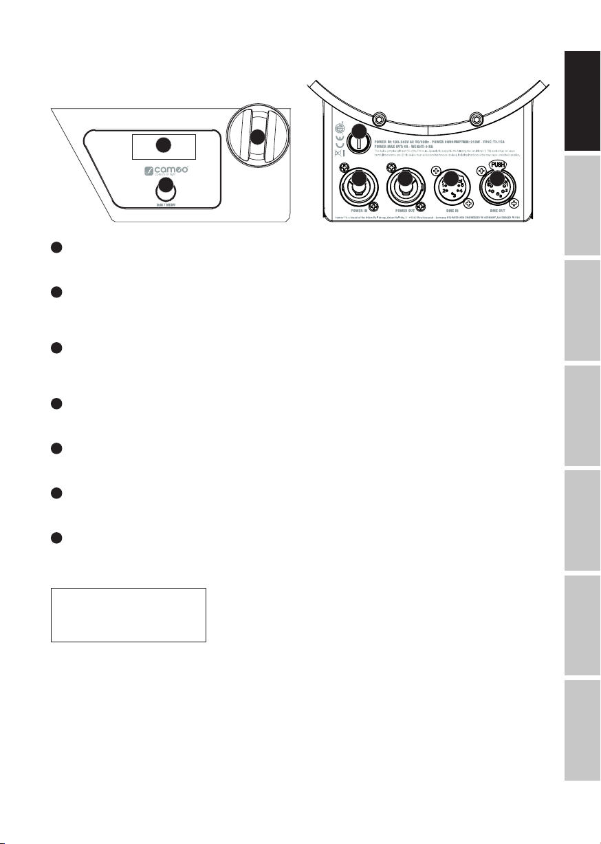
CONNECTIONS, OPERATING AND DISPLAY ELEMENTS
6
7
1
POWER IN
Neutrik powerCON mains input socket. Operating voltage 100 - 240 V AC / 50 - 60Hz.
2
POWER OUT
Neutrik powerCON power output socket for the power supply of additional CAMEO spotlights. Ensure that the total current consumption of
all connected devices does not exceed the value specified on the device in amperes (A).
3
FUSE
Fuse holder for 5 x 20mm micro fuses. IMPORTANT: Replace the fuse only with a fuse of the same type and value (T3,15A/250V). In the
event of repeated fuse failure, please contact an authorised service centre.
4
DMX IN
Male 5-pin XLR socket for connection to a DMX control device (e.g. DMX console).
5
DMX OUT
Female 5-pin XLR socket for sending the DMX control signal.
6
OLED DISPLAY
Displays currently active mode and the menu items in the Edit menu.
8
3
1 2 4 5
ENGLISH
DEUTSCHFRANCAIS
ESPAÑOL
7
DIM/MENU
Rotary-push encoder for the adjustment and control of the spotlight.
DIM – If one of the DMX modes is enabled and there is no DMX signal to the device, the encoder serves as master dimmer control and you
can set the brightness of the spotlight with values from 000 to 255 by turning the encoder (Quicklight).
Quicklight
000-255
MENU – Push the encoder to access the main menu and select menu items by turning the encoder.
ITALIANO POLSKI
DMX
5
---------------- Menu ----------------
DMX Address
DMX mode
Stand Alone
Slave
Settings
System Info
DEUTSCHENGLISH
8
ZOOM
On either side of the cabinet is a calibration control to manually adjust the beam angle. The two controls are mechanically linked and are
directly opposite each other on the housing. Turn the calibration control to adjust the beam angle of the spotlight continuously from 40° to
15°. A rack and pinion system moves the zoom tube with the Fresnel lens in and out of the housing. The further the zoom tube protrudes
from the housing, the smaller the beam angle. A stop mechanism prevents the tube from becoming detached from the housing.
FRANCAIS
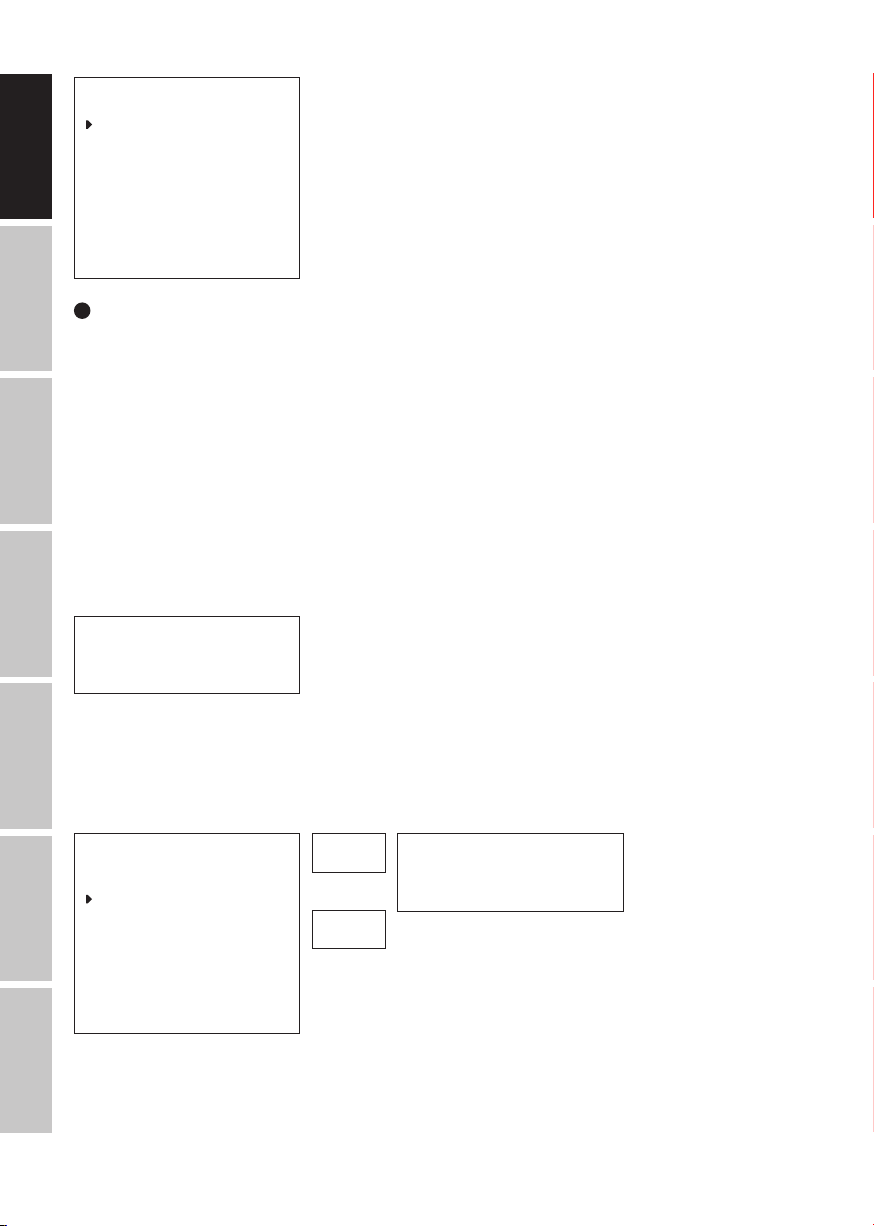
OPERATION
TIPS
• As soon as the spotlight is correctly is connected to the power supply, the following will be displayed in succession: “Welcome to Cameo”,
the model name and the software version. After this process, the lamp is ready for operation and starts in the previously enabled mode.
• If one of the DMX modes or slave mode is enabled and there is no control signal at the DMX input, the characters in the display will start
to flash.
• If no input is made within approximately 30 seconds, the currently activated mode is automatically shown in the display (main display).
ESPAÑOL
MAIN DISPLAY
The main display shows the currently activated mode (in the example DMX mode with DMX start address 001).
DMX Address
001
POLSKI
SETTING DMX START ADDRESS (DMX ADDRESS)
Press the encoder to access the main menu. Rotate the encoder to select the menu item “DMX Address” (left arrow) and confirm by pushing the
encoder. You can now configure the DMX start address as required by rotating the encoder (the highest value depends on the selected DMX mode).
Confirm the entry by pushing the encoder. Select the arrow symbol at the top of the menu for “back” and push the encoder to return to the main
display. The main display is activated automatically if no input is made within approximately 30 seconds. DMX mode is automatically activated
when setting the DMX start address.
ITALIANO
DMX
---------------- Menu ----------------
DMX Address
DMX mode
Stand Alone
Slave
Settings
System Info
001
–
5xx
DMX Address
001
6

CONFIGURING DMX MODE (DMX Mode)
Press the encoder to access the main menu. Rotate the encoder to select the menu item “DMX Mode” (left arrow) and confirm by pushing
the encoder. You can now select the desired DMX mode by rotating the encoder (5CH, 4CH, 3CH, 2CH 2, 2CH 1, 1CH). Confirm the selection
by pushing the encoder. Select the arrow symbol at the top of the menu for “back” and push the encoder to return to the main display. The
main display is activated automatically if no input is made within approximately 30 seconds. Tables with the channel assignment of the
different DMX modes can be found in these instructions under DMX CONTROL.
---------------- Menu ----------------
DMX Address
DMX Mode
Stand Alone
Slave
Settings
System Info
STATIC MODE
Press the encoder to access the main menu. Rotate the encoder to select the menu item “Stand Alone” (left arrow) and confirm by pushing
the encoder. Now select the submenu item “Dimmer” and confirm by pushing the encoder and rotate the encoder to set the desired brightness with values between 000 (blackout) and 255 (maximum brightness). Confirm your entry by pressing the encoder. A stroboscopic effect
can now be activated as required and set in the same way (strobe value 000 = strobe off. Value 001 = lowest flash frequency. Value 255 =
highest flash frequency). Now select the arrow symbol for “back” at the top of the submenu. Push the encoder and access the main menu in
the same way to return to the main display.
---------------- Menu ----------------
DMX Address
DMX mode
Stand Alone
Slave
Settings
System Info
------------ DMX Mode ------------
5CH
4CH
3CH
2CH 2
2CH 1
1CH
----------- Stand Alone ----------
Dimmer <255>
Strobe <255>
000
–
255
DMX Address
001
Mode
Static
ENGLISH
DEUTSCHFRANCAIS
ESPAÑOL
SLAVE MODE
Press the encoder to access the main menu. Rotate the encoder to select the menu item “Slave” (left arrow) and confirm by pushing the
encoder. Slave mode is now enabled, and the main display is automatically displayed. Connect the slave and the master units (same model)
with a DMX cable and enable the standalone mode static on the master unit. Now the slave unit will follow the master unit.
---------------- Menu ----------------
DMX Address
DMX mode
Stand Alone
Slave
Settings
System Info
Mode
Slave
ITALIANO POLSKI
DMX
7
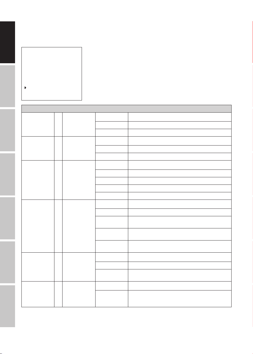
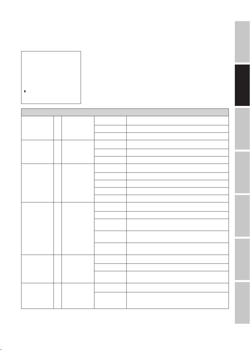
DEVICE SETTINGS (Settings)
Press the encoder to access the main menu. Rotate the encoder to select the menu item “Settings” (left arrow) and confirm by pushing the
encoder. This will take you to the submenu for setting the submenu items (see table, rotate the encoder to select and push the encoder to
confirm selection). Now select the arrow symbol for “back” at the top of the submenu. Push the encoder and access the main menu in the
same way to return to the main display. The main display is activated automatically if no input is made within approximately 30 seconds.
---------------- Menu ----------------
DMX Address
DMX mode
DEUTSCHENGLISH
Stand Alone
Slave
Settings
System Info
Settings
Display Reverse = Flip display
FRANCAIS
Display Backlight = Display lighting
ESPAÑOL
DMX Fail = operating status
Dimmer Curve = dimmer curve
POLSKI
ITALIANO
Dimmer Response = Dimmer response
LED Frequency = LED PWM
DMX
with DMX signal
fault
frequency
On Rotate display by 180° (e.g. for overhead installation)
Off No display rotation
On On permanently
Off Deactivation after approximately 1 minute of inactivity
Hold Last command is retained
Blackout Activates blackout
Full On Spotlight switches to full on
Stand Alone Spotlight switches to stand-alone mode
Linear Light intensity increases linearly with DMX value
Exponential Light intensity can be finely adjusted at lower DMX values and
Logarithmic Light intensity can be broadly adjusted at lower DMX values and
S-Curve Light intensity can be finely adjusted at lower and higher DMX
LED Lamp responds abruptly to changes in DMX value
Halogen Lamp behaves like a halogen spotlight with soft brightness
800Hz / 1200Hz /
2000Hz / 3600Hz
/ 12kHz / 25kHz
Back
Back
Back
Back
broadly adjusted at higher DMX values
finely adjusted at higher DMX values
values and broadly adjusted at medium DMX values
Back
changes
Back
Configuration of LED PWM frequency
8
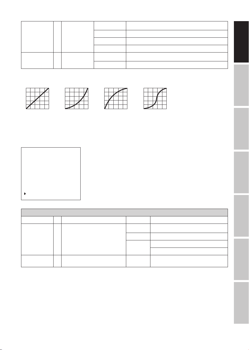
Fan = Adjusts fan speed
Factory Reset = resets to factory
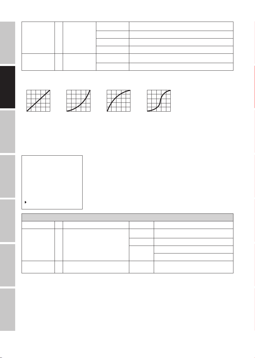
DIMMER CURVES
linear
setting
exponential
Auto Automatic fan speed control
Max Intensity Maximum fan power for maximum brightness
Low Noise Extra quiet fan with reduced brightness
Reset Now! reset to factory settings
logarithmic
Back
Back
S-curve
ENGLISH
DEUTSCHFRANCAIS
Light intensity
DMX value
SYSTEM INFORMATION (System Info)
Press the encoder to access the main menu. Rotate the encoder to select the menu item "System info" (left arrow) and confirm by pushing the
encoder. This will take you to the submenu for selecting the submenu items (see table, rotate the encoder to select and push the encoder to confirm
selection). Now select the arrow symbol for "back" at the top of the submenu. Push the encoder and access the main menu in the same way to
return to the main display. The main display is activated automatically if no input is made within approximately 30 seconds.
---------------- Me
DMX Address
DMX mode
Stand Alone
Slave
Settings
System Info
System Info
Firmware = Displays device firmware Main CPU Vx.xx
Temperature = Displays temperature of LED unit
Operation Hours = Displays operating time xx:xx h Displays total operating time in hours and
Light intensity
DMX value
nu ----------------
Light intensity
DMX value
Light intensity
DMX value
LED xx°C / xx°F
Unit °C (= display in degrees Celsius)
Back
°F (= display in degrees Fahrenheit)
minutes
ESPAÑOL
ITALIANO POLSKI
DMX
9

INSTALLATION
Thanks to its four plastic feet, the spotlight can be positioned in a suitable location on a level surface. Mounting to a traverse is possible
with the pre-installed mounting bracket (A) and a suitable traverse clamp (optional). Ensure firm connections and secure the spotlight by
attaching a suitable safety cable to the securing lug on top of the housing and intended for this purpose (B). Use the side-mounted lever
screws (C) to adjust the vertical beam angle.
Important: Overhead mounting requires extensive experience, including the calculation of the load limit values of the installation material
and regular safety inspection of all installation materials and spotlights. If you do not have these qualifications, do not attempt to perform an
installation yourself. Refer instead to a qualified professional.
DEUTSCHENGLISH
A
B
FRANCAIS
C
ESPAÑOL
INSTALLATION/REMOVAL OF BARN DOORS AND FILTER FRAME
To install or remove the barn doors and the filter frame please push the spring-loaded locking pin (E) of the bracket so that it folds upwards.
Then return the bracket to its original position so that the locking pin re-engages.
POLSKI
E
ITALIANO
DMX
10
DMX TECHNOLOGY
DMX-512
DMX (Digital Multiplex) is the designation for a universal transmission protocol for
communications between corresponding devices and controllers. A DMX controller sends
DMX data to the connected DMX device(s). The DMX data is always transmitted as a serial
data stream that is forwarded from one connected device to the next via the "DMX IN" and
"DMX OUT" connectors (XLR plug-type connectors) that are found on every DMX-capable
device, provided the maximum number of devices does not exceed 32 units. The last device
in the chain needs to be equipped with a terminator (terminating resistor).
DMX CONNECTION
DMX is the common "language" via which a very wide range of types and models of equipment from various manufacturers can
be connected with one another and controlled via a central controller, provided that all of the devices and the controller are DMX
compatible. For optimum data transmission, it is necessary to keep the connecting cables between the individual devices as short as
possible. The order in which the devices are integrated in the DMX network has no influence on the addresses. Thus the device with
the DMX address 1 can be located at any position in the (serial) DMX chain: at the beginning, at the end or somewhere in the middle.
If the DMX address 1 is assigned to a device, the controller "knows" that it should send all data allocated to address 1 to this device
regardless of its position in the DMX network.
SERIAL CONNECTION OF MULTIPLE LIGHTS
1. Connect the male XLR connector (3-pin or 5-pin) of the DMX cable to the DMX output (female XLR socket) of the first DMX device
(e.g. DMX-Controller).
2. Connect the female 3-pin XLR connector of the DMX cable connected to the first projector to the DMX input (male 3-pin socket)
of the next DMX device. In the same way, connect the DMX output of this device to the DMX input of the next device and repeat until
all devices have been connected. Please note that as a rule, DMX devices are connected in series and connections cannot be shared
without active splitters. The maximum number of DMX devices in a DMX chain should not exceed 32 units.
The Adam Hall 3 STAR, 4 STAR, and 5 STAR product ranges include an extensive selection of suitable cables.
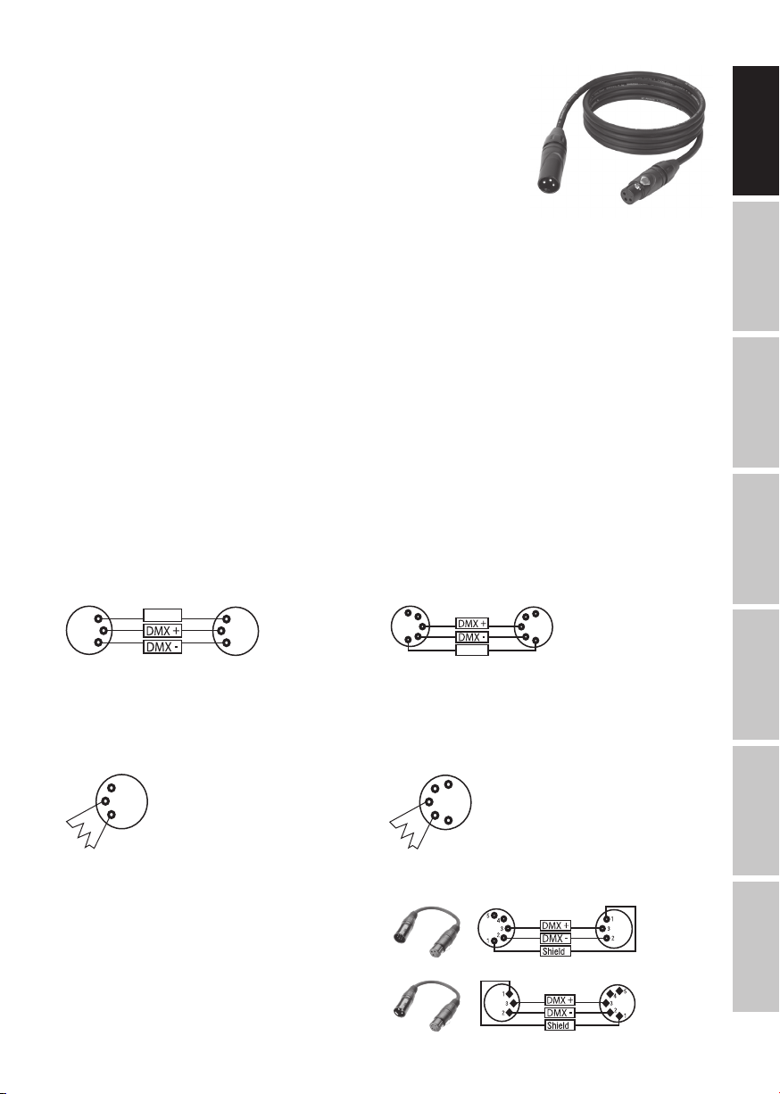
DMX CABLES
When fabricating your own cables, always observe the illustrations on this page. Never connect the shielding of the cable to the ground
contact of the plug, and always make certain that the shielding does not come into contact with the housing of the XLR plug. If the shielding
is connected to the ground, this can lead to short-circuiting and system malfunctions.
Pin Assignment
DMX cable with 3-pin XLR connectors: DMX cable with 5-pin XLR connectors (pin 4 and 5 are not used):
1
3
2
Shield
1
3
2
5
4
3
2
1
Shield
DMX TERMINATORS (TERMINATING RESISTORS)
To prevent system errors, the last device in a DMX chain needs to be equipped with a terminating resistor (120 ohm, 1/4 Watt).
3-pin XLR connector with a terminating resistor: K3DMXT3
5-pin XLR connector with a terminating resistor: K3DMXT5
Pin Assignment
3-pin XLR connector: 5-pin XLR connector:
1
3
2
5
4
3
2
1
DMX ADAPTER
The combination of DMX devices with 3-pin connectors and DMX devices with 5-pin connectors in a DMX chain is possible with suitable
adapters.
Pin Assignment
DMX Adapter 5-pin XLR male to 3-pin XLR female: K3DGF0020
Pins 4 and 5 are not used.
Pin Assignment
DMX Adapter 3-pin XLR male to 5-pin XLR female: K3DHM0020
Pins 4 and 5 are not used.
5
4
3
2
1
ENGLISH
DEUTSCHFRANCAIS
ESPAÑOL
ITALIANO POLSKI
DMX
11
TECHNICAL DATA
Product number: CLF2T CLF2D
Product type: LED spotlight LED spotlight
Type: Fresnel spotlight with zoom function Fresnel spotlight with zoom function
Colour spectrum: Tungsten (warm white) 3200K Daylight 5400K
CRI: 97 96
Number of LEDs: 1 1
DEUTSCHENGLISH
LED type: 240 W 240 W
LED PWM frequency: 800 Hz, 1200 Hz, 2000 Hz, 3600 Hz, 12 kHz,
Beam angle: 15-40° 15-40°
DMX input: 5-pin male XLR 5-pin male XLR
DMX output: 5-pin female XLR 5-pin female XLR
FRANCAIS
DMX modes: 1-channel, 2-channel 1, 2-channel 2, 3-channel
DMX functions: Dimmer, dimmer fine, strobe, dimmer curve, dim-
Control: DMX512, RDM-enabled DMX512, RDM-enabled
Standalone functions: Dimmer, Strobe, Master/Slave Dimmer, Strobe, Master/Slave
Operating controls: DIM/MENU rotary-push encoder, manual zoom DIM/MENU rotary-push encoder, manual zoom
ESPAÑOL
Display elements: OLED display OLED display
Operating voltage: 100–240 V AC/50–60 Hz 100–240 V AC/50–60 Hz
Power consumption: 220 W 220 W
Lighting power: 14000 lm 15000 lm
Power connection: INPUT: Neutrik powerCON
POLSKI
Fuse: T3, 15 A / 250 V (5 x 20 mm) T3, 15 A / 250 V (5 x 20 mm)
Ambient temperature
(in operation):
Relative air humidity: < 80%, non-condensing < 80%, non-condensing
Housing material: Die-cast metal Die-cast metal
Housing colour: black black
ITALIANO
Housing cooling: Temperature-controlled fan + heat pipe Temperature-controlled fan + heat pipe
Dimensions (W x H x D,
without bracket and barn
doors):
Weight: 9 kg 9 kg
Additional features: 200 mm Fresnel lens, power cable, filter frame,
25 kHz (adjustable)
4-channel, 5-channel
mer response, PWM frequency, fan setting
OUTPUT: Neutrik powerCON (max. 6 A)
0–40°C 0–40°C
270 x 292 x 322 mm 270 x 292 x 322 mm
8-position barn doors and mounting bracket
supplied, manual zoom
800 Hz, 1200 Hz, 2000 Hz, 3600 Hz, 12 kHz,
25 kHz (adjustable)
1-channel, 2-channel 1, 2-channel 2, 3-channel
4-channel, 5-channel
Dimmer, dimmer fine, strobe, dimmer curve, dimmer response, PWM frequency, fan setting
INPUT: Neutrik powerCON
OUTPUT: Neutrik powerCON (max. 6 A)
200 mm Fresnel lens, power cable, filter frame,
8-position barn doors and mounting bracket
supplied, manual zoom
DMX
12

MANUFACTURER´S DECLARATIONS
MANUFACTURER‘S WARRANTY & LIMITATIONS OF LIABILITY
You can find our current warranty conditions and limitations of liability at: https://cdn-shop.adamhall.com/media/pdf/Manufacturers-Declarations-CAMEO_DE_EN_ES_FR.pdf. To request warranty service for a product, please contact Adam Hall GmbH, Adam-Hall-Str. 1,
61267 Neu Anspach / Email: Info@adamhall.com / +49 (0)6081 / 9419-0.
CORRECT DISPOSAL OF THIS PRODUCT
(valid in the European Union and other European countries with a differentiated waste collection system)
This symbol on the product, or on its documents indicates that the device may not be treated as household waste. This is to avoid
environmental damage or personal injury due to uncontrolled waste disposal. Please dispose of this product separately from other waste
and have it recycled to promote sustainable economic activity. Household users should contact either the retailer where they purchased
this product, or their local government office, for details on where and how they can recycle this item in an environmentally friendly manner.
Business users should contact their supplier and check the terms and conditions of the purchase contract. This product should not be mixed
with other commercial waste for disposal.
FCC STATEMENT
This device complies with Part 15 of the FCC Rules. Operation is subject to the following two conditions:
(1) This device may not cause harmful interference, and
(2) This device must accept any interference received, including interference that may cause undesired operation
CE Compliance
Adam Hall GmbH states that this product meets the following guidelines (where applicable):
R&TTE (1999/5/EC) or RED (2014/53/EU) from June 2017
Low voltage directive (2014/35/EU)
EMV directive (2014/30/EU)
RoHS (2011/65/EU)
The complete declaration of conformity can be found at www.adamhall.com.
Furthermore, you may also direct your enquiry to info@adamhall.com.
ENGLISH
DEUTSCHFRANCAIS
ESPAÑOL
13
ITALIANO POLSKI
DMX

DEUTSCH
SIE HABEN DIE RICHTIGE WAHL GETROFFEN!
Dieses Gerät wurde unter hohen Qualitätsanforderungen entwickelt und gefertigt, um viele Jahre einen reibungslosen Betrieb zu gewährleisten. Bitte lesen Sie diese Bedienungsanleitung sorgfältig, damit Sie Ihr neues Produkt von Cameo Light schnell und optimal einsetzen
können. Weitere Informationen über Cameo Light erhalten Sie auf unserer Website WWW.CAMEOLIGHT.COM.
SICHERHEITSHINWEISE
1. Lesen Sie diese Anleitung bitte sorgfältig durch.
2. Bewahren Sie alle Informationen und Anleitungen an einem sicheren Ort auf.
3. Befolgen Sie die Anweisungen.
DEUTSCHENGLISH
4. Beachten Sie alle Warnhinweise. Entfernen Sie keine Sicherheitshinweise oder andere Informationen vom Gerät.
5. Verwenden Sie das Gerät nur in der vorgesehenen Art und Weise.
6. Verwenden Sie ausschließlich stabile und passende Stative bzw. Befestigungen (bei Festinstallationen). Stellen Sie sicher, dass Wandhalterungen
ordnungsgemäß installiert und gesichert sind. Stellen Sie sicher, dass das Gerät sicher installiert ist und nicht herunterfallen kann.
7. Beachten Sie bei der Installation die für Ihr Land geltenden Sicherheitsvorschriften.
8. Installieren und betreiben Sie das Gerät nicht in der Nähe von Heizkörpern, Wärmespeichern, Öfen oder sonstigen Wärmequellen. Sorgen
Sie dafür, dass das Gerät immer so installiert ist, dass es ausreichend gekühlt wird und nicht überhitzen kann.
9. Platzieren Sie keine Zündquellen wie z.B. brennende Kerzen auf dem Gerät.
10. Lüftungsschlitze dürfen nicht blockiert werden.
11. Das Gerät wurde ausschließlich für die Verwendung in Innenräumen entwickelt, betreiben Sie das Gerät nicht in unmittelbarer Nähe von
FRANCAIS
Wasser (gilt nicht für spezielle Outdoor Geräte - beachten Sie in diesem Fall bitte die im Folgenden vermerkten Sonderhinweise). Bringen Sie
das Gerät nicht mit brennbaren Materialien, Flüssigkeiten oder Gasen in Berührung.
12. Sorgen Sie dafür, dass kein Tropf- oder Spritzwasser in das Gerät eindringen kann. Stellen Sie keine mit Flüssigkeit gefüllten Behältnisse
wie Vasen oder Trinkgefäße auf das Gerät.
13. Sorgen Sie dafür, dass keine Gegenstände in das Gerät fallen können.
14. Betreiben Sie das Gerät nur mit dem vom Hersteller empfohlenen und vorgesehenen Zubehör.
15. Öffnen Sie das Gerät nicht und verändern Sie es nicht.
16. Überprüfen Sie nach dem Anschluss des Geräts alle Kabelwege, um Schäden oder Unfälle, z. B. durch Stolperfallen zu vermeiden.
17. Achten Sie beim Transport darauf, dass das Gerät nicht herunterfallen und dabei möglicherweise Sach- und Personenschäden verursachen kann.
ESPAÑOL
18. Wenn Ihr Gerät nicht mehr ordnungsgemäß funktioniert, Flüssigkeiten oder Gegenstände in das Geräteinnere gelangt sind, oder das Gerät
anderweitig beschädigt wurde, schalten Sie es sofort aus und trennen es von der Netzsteckdose (sofern es sich um ein aktives Gerät handelt).
Dieses Gerät darf nur von autorisiertem Fachpersonal repariert werden.
19. Verwenden Sie zur Reinigung des Geräts ein trockenes Tuch.
20. Beachten Sie alle in Ihrem Land geltenden Entsorgungsgesetze. Trennen Sie bei der Entsorgung der Verpackung bitte Kunststoff und
Papier bzw. Kartonagen voneinander.
21. Kunststoffbeutel müssen außer Reichweite von Kindern aufbewahrt werden.
BEI GERÄTEN MIT NETZANSCHLUSS:
22. ACHTUNG: Wenn das Netzkabel des Geräts mit einem Schutzkontakt ausgestattet ist, muss es an einer Steckdose mit Schutzleiter
POLSKI
angeschlossen werden. Deaktivieren Sie niemals den Schutzleiter eines Netzkabels.
23. Schalten Sie das Gerät nicht sofort ein, wenn es starken Temperaturschwankungen ausgesetzt war (beispielsweise nach dem Transport).
Feuchtigkeit und Kondensat könnten das Gerät beschädigen. Schalten Sie das Gerät erst ein, wenn es Zimmertemperatur erreicht hat.
24. Bevor Sie das Gerät an die Steckdose anschließen, prüfen Sie zuerst, ob die Spannung und die Frequenz des Stromnetzes mit den auf
dem Gerät angegebenen Werten übereinstimmen. Verfügt das Gerät über einen Spannungswahlschalter, schließen Sie das Gerät nur an die
Steckdose an, wenn die Gerätewerte mit den Werten des Stromnetzes übereinstimmen. Wenn das mitgelieferte Netzkabel bzw. der mitgelieferte Netzadapter nicht in Ihre Netzsteckdose passt, wenden Sie sich an Ihren Elektriker.
25. Treten Sie nicht auf das Netzkabel. Sorgen Sie dafür, dass spannungsführende Kabel speziell an der Netzbuchse bzw. am Netzadapter
und der Gerätebuchse nicht geknickt werden.
ITALIANO
26. Achten Sie bei der Verkabelung des Geräts immer darauf, dass das Netzkabel bzw. der Netzadapter stets frei zugänglich ist. Trennen Sie
das Gerät stets von der Stromzuführung, wenn das Gerät nicht benutzt wird, oder Sie das Gerät reinigen möchten. Ziehen Sie Netzkabel und
Netzadapter immer am Stecker bzw. am Adapter und nicht am Kabel aus der Steckdose. Berühren Sie Netzkabel und Netzadapter niemals
mit nassen Händen.
27. Schalten Sie das Gerät möglichst nicht schnell hintereinander ein und aus, da sonst die Lebensdauer des Geräts beeinträchtigt werden könnte.
28. WICHTIGER HINWEIS: Ersetzen Sie Sicherungen ausschließlich durch Sicherungen des gleichen Typs und Wertes. Sollte eine Sicherung
wiederholt auslösen, wenden Sie sich bitte an ein autorisiertes Servicezentrum.
29. Um das Gerät vollständig vom Stromnetz zu trennen, entfernen Sie das Netzkabel bzw. den Netzadapter aus der Steckdose.
30. Wenn Ihr Gerät mit einem Volex-Netzanschluss bestückt ist, muss der passende Volex-Gerätestecker entsperrt werden, bevor er entfernt
werden kann. Das bedeutet aber auch, dass das Gerät durch ein Ziehen am Netzkabel verrutschen und herunterfallen kann, wodurch Personen verletzt werden und/oder andere Schäden auftreten können. Verlegen Sie Ihre Kabel daher immer sorgfältig.
DMX
31. Entfernen Sie Netzkabel und Netzadapter aus der Steckdose bei Gefahr eines Blitzschlags oder wenn Sie das Gerät länger nicht verwenden.
32. Das Gerät darf nur im spannungsfreien Zustand (Trennung des Netzsteckers vom Stromnetz) installiert werden.
33. Staub und andere Ablagerungen im Inneren des Geräts können es beschädigen. Das Gerät sollte je nach Umgebungsbedingungen
(Staub, Nikotin, Nebel etc.) regelmäßig von qualifiziertem Fachpersonal gewartet bzw. gesäubert werden (keine Garantieleistung),
um Überhitzung und Fehlfunktionen zu vermeiden.
34. Der Abstand zu brennbaren Materialien muss mindestens 0,5 m betragen.
35. Netzleitungen zur Spannungsversorgung mehrerer Geräte müssen mindestens 1,5 mm² Aderquerschnitt aufweisen. In der EU müssen
14

die Leitungen H05VV-F, oder gleichartig, entsprechen. Geeignete Leitungen werden von Adam Hall angeboten. Mit diesen Leitungen können
Sie mehrere Geräte über den Power out Anschluss mit dem Power IN Anschluss eines weiteren Gerätes verbinden. Beachten Sie, dass die
gesamte Stromaufnahme aller angeschlossenen Geräte den vorgegebenen Wert nicht überschreitet (Aufdruck auf dem Gerät). Achten Sie
darauf, Netzleitungen so kurz wie möglich zu halten.
ACHTUNG
Entfernen Sie niemals die Abdeckung, da sonst das Risiko eines elektrischen Schlages besteht. Im
Inneren des Geräts befinden sich keine Teile, die vom Bediener repariert oder gewartet werden können.
Lassen Sie Wartung und Reparaturen ausschließlich von qualifiziertem Servicepersonal durchführen.
Das gleichseitige Dreieck mit Blitzsymbol warnt vor nichtisolierten, gefährlichen Spannungen im Geräteinneren, die einen
elektrischen Schlag verursachen können.
Das gleichseitige Dreieck mit Ausrufungszeichen kennzeichnet wichtige Bedienungs- und Wartungshinweise.
Die Gehäuseoberfläche des Scheinwerfers kann sich im regulären Betrieb auf bis zu 70°C erwärmen. Stellen Sie sicher, dass ein
versehentliches Berühren des Gehäuses ausgeschlossen ist. Lassen Sie die Lampe vor dem Abbau, vor Wartungsarbeiten und vor
dem Aufladen etc. immer ausreichend abkühlen.
Warnung! Dieses Gerät ist für eine Nutzung bis zu einer Höhe von maximal 2000 Metern über dem Meeresspiegel bestimmt.
Warnung! Dieses Gerät ist nicht für den Einsatz in tropischen Klimazonen bestimmt.
ENGLISH
DEUTSCHFRANCAIS
VORSICHT! WICHTIGE HINWEISE IN BEZUG AUF LICHT-PRODUKTE!
1. Das Produkt ist für den professionellen Einsatz im Bereich der Veranstaltungstechnik entwickelt worden und ist nicht für die Raumbeleuchtung in
Haushalten geeignet.
2. Blicken Sie niemals, auch nicht kurzzeitig, direkt in den Lichtstrahl.
3. Blicken Sie niemals mit optischen Geräten wie Vergrößerungsgläsern in den Lichtstrahl.
4. Stroboskopeffekte können unter Umständen bei empfindlichen Menschen epileptische Anfälle auslösen! Epilepsiekranke Menschen
sollten daher unbedingt Orte meiden, an denen Stroboskope eingesetzt werden.
Vorsicht! Intensive LED Lichtquelle! Gefahr der Augenschädigung. Nicht in die Lichtquelle blicken.
EINFÜHRUNG
STEUERUNGSFUNKTIONEN
1-Kanal, 2-Kanal 1, 2-Kanal 2, 3-Kanal, 4-Kanal und 5-Kanal DMX-Steuerung
Master / Slave Betrieb
Standalone Funktionen
EIGENSCHAFTEN
15° - 40° Abstrahlwinkel, manueller Zoom. 200mm Fresnel-Linse. PWM Frequenz einstellbar (Flicker free). DMX-512 Steuerung. RDM
enabled. Manuelle Steuerung. Quicklight Funktion. 4 Dimmerkurven. 16 Bit Dimming. Master- / Slave-Betrieb. Extrem leiser Betrieb durch
Kombination aus Heatpipe-Kühlung und Lüfter. Betriebsspannung 100V - 240V AC / 50 - 60Hz. Leistungsaufnahme 210W. Montagebügel,
Filterrahmen und 8-Wege Flügelbegrenzer inklusive.
LEUCHTMITTEL CLF2T
1 x High Power 240W Tungsten-LED (warmweiß).
LEUCHTMITTEL CLF2D
1 x High Power 240W Tageslicht-LED.
Beide Scheinwerfer verfügen über den RDM-Standard (Remote Device Management). Diese Gerätefernverwaltung ermöglicht die Statusabfrage und Konfiguration von RDM-Endgeräten über einen RDM-fähigen Controller.
ESPAÑOL
ITALIANO POLSKI
DMX
15

ANSCHLÜSSE, BEDIEN- UND ANZEIGEELEMENTE
6
DEUTSCHENGLISH
1
POWER IN
Neutrik powerCON Netzeingangsbuchse. Betriebsspannung 100 - 240V AC / 50 - 60Hz.
FRANCAIS
2
POWER OUT
Neutrik powerCON Netzausgangsbuchse für die Netzversorgung weiterer CAMEO Scheinwerfer. Achten Sie darauf, dass die gesamte Stromaufnahme aller angeschlossenen Geräte den auf dem Gerät in Ampere (A) angegebenen Wert nicht überschreitet.
3
FUSE
Sicherungshalter für 5 x 20mm Feinsicherungen. WICHTIGER HINWEIS: Ersetzen Sie die Sicherung ausschließlich durch eine Sicherung des
gleichen Typs und mit gleichen Werten (T3,15A/250V). Sollte die Sicherung wiederholt auslösen, wenden Sie sich bitte an ein autorisiertes
Servicezentrum.
ESPAÑOL
4
DMX IN
Männliche 5-Pol XLR-Buchse zum Anschließen eines DMX-Kontrollgeräts (z.B. DMX-Pult).
5
DMX OUT
Weibliche 5-Pol XLR-Buchse zum Weiterleiten des DMX-Steuersignals.
POLSKI
6
OLED DISPLAY
Anzeige der aktuell aktivierten Betriebsart und der Menüpunkte im Bearbeitungsmenü.
7
8
3
1 2 4 5
7
DIM / MENU
Dreh-Drück-Encoder zum Einstellen und Steuern des Scheinwerfers.
DIM - Ist eine der DMX-Betriebsarten aktiviert und es liegt kein DMX-Signal am Gerät an, hat der Encoder die Funktion des Master-Dimmers
und Sie können die Helligkeit des Scheinwerfers direkt durch Drehen am Encoder mit Werten von 000 bis 255 einstellen (Quicklight).
ITALIANO
Quicklight
000 - 255
DMX
16

MENU - Durch Drücken auf den Encoder gelangen Sie in das Hauptmenü, durch Drehen am Encoder wählen Sie die Menüpunkte.
---------------- Menu ----------------
DMX Address
DMX Mode
Stand Alone
Slave
Settings
System Info
8
ZOOM
An beiden Seiten des Gehäuses befindet sich ein Justierknopf zum manuellen Einstellen des Abstrahlwinkels. Die beiden Knöpfe liegen am
Gehäuse direkt gegenüber und sind mechanisch miteinander verbunden. Durch Drehen an einem Justierknopf kann der Abstrahlwinkel
des Scheinwerfers stufenlos von 40° bis 15° eingestellt werden, dabei wird der Zoom-Tubus mit der Fresnel-Linse dank Zahnrad und
Zahnstange aus dem, bzw. in das Gehäuse geschoben. Je weiter der Zoom-Tubus aus dem Gehäuse ragt, desto kleiner der Abstrahlwinkel,
dank einer Stoppvorrichtung kann der Tubus nicht aus dem Gehäuse entfernt werden.
BEDIENUNG
HINWEISE
• Sobald der Scheinwerfer korrekt am Stromnetz angeschlossen ist, werden während des Startvorgangs nacheinander „Welcome to
Cameo“, die Modellbezeichnung und die Software Version im Display angezeigt. Nach diesem Vorgang ist der Scheinwerfer betriebsbereit
und startet in der Betriebsart, die zuvor aktiviert war.
• Ist eine der DMX-Betriebsarten oder der Slave-Betrieb aktiviert und es liegt kein Steuersignal am DMX-Eingang an, beginnen die Zeichen
im Display zu blinken.
• Wenn innerhalb von circa 30 Sekunden keine Eingabe erfolgt, wird automatisch die aktuell aktivierte Betriebsart im Display angezeigt
(Hauptanzeige).
DISPLAY HAUPTANZEIGE
Die Hauptanzeige zeigt die aktuell aktivierte Betriebsart (im Beispiel DMX-Betriebsart mit DMX-Startadresse 001).
ENGLISH
DEUTSCHFRANCAIS
ESPAÑOL
DMX Address
001
DMX-STARTADRESSE EINSTELLEN (DMX Address)
Durch Drücken auf den Encoder gelangen Sie in das Hauptmenü. Durch Drehen des Encoders wählen Sie nun den Menüpunkt „DMX Address“
aus (Auswahlpfeil links beachten) und bestätigen durch Drücken auf den Encoder. Nun können Sie die DMX-Startadresse wunschgemäß durch
Drehen des Encoders einstellen (höchster Wert abhängig von der aktivierten DMX-Betriebsart). Bestätigen Sie die Eingabe durch Drücken auf den
Encoder, wählen nun das Pfeilsymbol für „zurück“ ganz oben im Menü und drücken auf den Encoder, um zur Hauptanzeige zurückzugelangen. Die
Hauptanzeige wird automatisch aktiviert, wenn innerhalb von circa 30 Sekunden keine Eingabe erfolgt. Beim Einstellen der DMX-Startadresse wird
die DMX-Betriebsart automatisch aktiviert.
-------------- Menu --------------
DMX Address
DMX Mode
Stand Alone
Slave
Settings
System Info
001
-
5xx
DMX Address
001
ITALIANO POLSKI
DMX
17

DMX BETRIEBSART EINSTELLEN (DMX Mode)
Durch Drücken auf den Encoder gelangen Sie in das Hauptmenü. Durch Drehen des Encoders wählen Sie nun den Menüpunkt „DMX
Mode“ aus (Auswahlpfeil links beachten) und bestätigen durch Drücken auf den Encoder. Nun können Sie die gewünschte DMX-Betriebsart
durch Drehen des Encoders auswählen (5CH, 4CH, 3CH, 2CH 2, 2Ch 1, 1CH). Bestätigen Sie die Auswahl durch Drücken auf den Encoder,
wählen nun das Pfeilsymbol für „zurück“ ganz oben im Menü und drücken auf den Encoder, um zur Hauptanzeige zurückzugelangen. Die
Hauptanzeige wird automatisch aktiviert, wenn innerhalb von circa 30 Sekunden keine Eingabe erfolgt. Tabellen mit der Kanalbelegung der
verschiedenen DMX-Modi finden Sie in dieser Anleitung unter DMX STEUERUNG.
-------------- Menu --------------
DEUTSCHENGLISH
DMX Address
DMX Mode
Stand Alone
Slave
Settings
System Info
FRANCAIS
STATISCHE BETRIEBSART (Static Mode)
Durch Drücken auf den Encoder gelangen Sie in das Hauptmenü. Durch Drehen des Encoders wählen Sie nun den Menüpunkt „Stand
Alone“ aus (Auswahlpfeil links beachten) und bestätigen durch Drücken auf den Encoder. Wählen Sie nun den Untermenüpunkt „Dimmer“
aus, bestätigen durch Drücken auf den Encoder und stellen die gewünschte Helligkeit mit Werten von 000 (Blackout) bis 255 (maximale
Helligkeit) durch Drehen am Encoder ein. Bestätigen Sie durch Drücken auf den Encoder. Ein Stroboskopeffekt kann nun in gleicher Weise
nach Wunsch aktiviert und eingestellt werden (Strobe Wert 000 = Stroboskop deaktiviert, Wert 001 = langsamste Blitzfrequenz, Wert 255
= schnellste Blitzfrequenz). Wählen Sie nun das Pfeilsymbol für „zurück“ ganz oben im Untermenü, drücken auf den Encoder und gehen in
gleicher Weise im Hauptmenü vor, um zur Hauptanzeige zurückzugelangen.
ESPAÑOL
POLSKI
-------------- Menu --------------
DMX Address
DMX Mode
Stand Alone
Slave
Settings
System Info
------------ DMX Mode -----------
5CH
4CH
3CH
2CH 2
2CH 1
1CH
----------- Stand Alone ----------
Dimmer <255>
Strobe <255>
000
-
255
DMX Address
001
Mode
Static
SLAVE-BETRIEB
Durch Drücken auf den Encoder gelangen Sie in das Hauptmenü. Durch Drehen des Encoders wählen Sie nun den Menüpunkt „Slave“ aus
(Auswahlpfeil links beachten) und bestätigen durch Drücken auf den Encoder. Die Slave-Betriebsart ist nun aktiviert und die Hauptanzeige
wird automatisch wieder angezeigt. Verbinden Sie die Slave- und die Master-Einheit (gleiches Modell) mit Hilfe eines DMX-Kabels und
aktivieren Sie in der Master-Einheit die Standalone Betriebsart Static. Nun folgt die Slave-Einheit der Master-Einheit.
ITALIANO
DMX
-------------- Menu --------------
DMX Address
DMX Mode
Stand Alone
Slave
Settings
System Info
Mode
Slave
18
GERÄTEEINSTELLUNGEN (Settings)
Durch Drücken auf den Encoder gelangen Sie in das Hauptmenü. Durch Drehen des Encoders wählen Sie nun den Menüpunkt „Settings“
aus (Auswahlpfeil links beachten) und bestätigen durch Drücken auf den Encoder. Daraufhin gelangen Sie in das Untermenü zum Einstellen
der Untermenü-Punkte (siehe Tabelle, Auswahl durch Drehen, bestätigen durch Drücken des Encoders). Wählen Sie nun das Pfeilsymbol für
„zurück“ ganz oben im Untermenü, drücken auf den Encoder und gehen in gleicher Weise im Hauptmenü vor, um zur Hauptanzeige zurückzugelangen. Die Hauptanzeige wird automatisch aktiviert, wenn innerhalb von circa 30 Sekunden keine Eingabe erfolgt.
-------------- Menu --------------
DMX Address
DMX Mode
Stand Alone
Slave
Settings
System Info
Settings
Display Reverse = Flip Display
Display Backlight = Display-Beleuch-
tung
DMX Fail = Betriebszustand
bei DMX-Signal-Unterbrechung
Dimmer Curve = Dimmerkurve
Dimmer Response = Dimmverhalten
LED Frequency = LED PWM
Frequenz
On Drehung der Display-Anzeige um 180° (z.B. Überkopfmontage)
Off keine Drehung der Display-Anzeige
On permanent an
Off Deaktivierung nach ca. 1 Minute Inaktivität
Hold letzter Befehl wird gehalten
Blackout aktiviert Blackout
Full On Scheinwerfer wechselt auf Full On
Stand Alone Scheinwerfer wechselt auf Betriebsart Stand Alone
Linear Die Lichtintensität steigt linear mit dem DMX-Wert an
Exponential Die Lichtintensität lässt sich im unteren DMX-Wertbereich fein
Logarithmic Die Lichtintensität lässt sich im unteren DMX-Wertbereich grob
S-Curve Die Lichtintensität lässt sich im unteren und oberen DMX-Wertbe-
Led Der Strahler reagiert abrupt auf Änderungen des DMX-Werts
Halogen Der Strahler verhält sich ähnlich einem Halogenstrahler mit
800Hz / 1200Hz /
2000Hz / 3600Hz
/ 12kHz / 25kHz
zurück
zurück
zurück
zurück
und im oberen DMX-Wertbereich grob einstellen
und im oberen DMX-Wertbereich fein einstellen
reich fein und im mittleren DMX-Wertbereich grob einstellen
zurück
sanften Helligkeitsänderungen
zurück
Einstellen der LED PWM Frequenz
ENGLISH
DEUTSCHFRANCAIS
ESPAÑOL
ITALIANO POLSKI
DMX
19
Fan = Lüftersteuerung
Factory Reset = Zurücksetzen auf
DEUTSCHENGLISH
DIMMERKURVEN
linear
anpassen
Werkseinstellung
exponentiell
Auto Automatische Regelung der Lüfterleistung
Max Intensity Maximale Lüfterleistung für maximale Helligkeit
Low Noise Extra leiser Lüfter bei reduzierter Helligkeit
Reset Now! Zurücksetzen auf Werkseinstellungen
logarithmisch
zurück
zurück
S-Kurve
Lichtintensität
FRANCAIS
ESPAÑOL
DMX-Wert
SYSTEMINFORMATIONEN (System Info)
Durch Drücken auf den Encoder gelangen Sie in das Hauptmenü. Durch Drehen des Encoders wählen Sie nun den Menüpunkt „System Info“
aus (Auswahlpfeil links beachten) und bestätigen durch Drücken auf den Encoder. Daraufhin gelangen Sie in das Untermenü zum Auswählen der
Untermenü-Punkte (siehe Tabelle, Auswahl durch Drehen, bestätigen durch Drücken des Encoders). Wählen Sie nun das Pfeilsymbol für „zurück“
ganz oben im Untermenü, drücken auf den Encoder und gehen in gleicher Weise im Hauptmenü vor, um zur Hauptanzeige zurückzugelangen. Die
Hauptanzeige wird automatisch aktiviert, wenn innerhalb von circa 30 Sekunden keine Eingabe erfolgt.
-------------- Menu --------------
DMX Address
DMX Mode
Stand Alone
Slave
Settings
System Info
Lichtintensität
DMX-Wert
Lichtintensität
DMX-Wert
Lichtintensität
DMX-Wert
POLSKI
System Info
Firmware = Anzeige der Geräte-Firmware Main CPU Vx.xx
Temperature = Temperaturanzeige der LED-Einheit
ITALIANO
Operation Hours = Betriebszeitanzeige xx:xxh Anzeige der Gesamtbetriebszeit in Stunden und
LED xx°C / xx°F
Unit °C (= Anzeige in Grad Celsius)
zurück
°F (= Anzeige in Grad Fahrenheit)
Minuten
DMX
20

AUFSTELLUNG UND MONTAGE
Dank seiner vier Plastikfüße kann der Scheinwerfer an einer geeigneten Stelle auf eine ebene Fläche gestellt werden. Die Montage an einer
Traverse erfolgt mit Hilfe des vormontierten Montagebügels (A) und einer geeigneten Traversenklemme (optional erhältlich). Sorgen Sie für
feste Verbindungen und sichern Sie den Scheinwerfer mit einem geeigneten Sicherungsseil an der dafür vorgesehenen Stelle auf der
Oberseite des Scheinwerfers (B). Nutzen Sie die auf einer Seite angebrachten Hebelschraube (C) zum Einstellen des vertikalen Abstrahlwinkels.
Wichtiger Hinweis: Überkopfmontage erfordert umfassende Erfahrung, einschließlich der Berechnung der Grenzwerte für die Arbeitslast,
des verwendeten Installationsmaterials und der regelmäßigen Sicherheitsüberprüfung aller Installationsmaterialien und Scheinwerfer.
Wenn Sie diese Qualifikationen nicht haben, versuchen Sie nicht, eine Installation selbst durchzuführen, sondern nutzen Sie die Hilfe von
professionellen Unternehmen.
A
ENGLISH
B
C
FLÜGELBEGRENZER UND FILTERRAHMEN MONTIEREN / DEMONTIEREN
Zum Montieren, bzw. Demontieren des Flügelbegrenzers und des Filterrahmens drücken Sie bitte auf den gefederten Verriegelungsbolzen
(E) der Haltevorrichtung, so, dass sie nach oben klappt. Bringen Sie die Haltevorrichtung danach wieder in die Ursprungsposition, so, dass
der Verriegelungsbolzen wieder einrastet.
E
DEUTSCHFRANCAIS
ESPAÑOL
21
ITALIANO POLSKI
DMX

DMX TECHNIK
DMX-512
DMX (Digital Multiplex) ist die Bezeichnung für ein universelles Übertragungsprotokoll für
die Kommunikation zwischen entsprechenden Geräten und Controllern. Ein DMX-Controller
sendet DMX-Daten an das/die angeschlossene(n) DMX-Gerät(e). Die DMX-Datenübertragung
erfolgt stets als serieller Datenstrom, der über die an jedem DMX-fähigen Gerät vorhandenen
DMX IN- und DMX OUT-Anschlüsse (XLR-Steckverbinder) von einem angeschlossenen
Gerät an das nächste weitergeleitet wird, wobei die maximale Anzahl der Geräte 32 nicht
überschreiten darf. Das letzte Gerät der Kette ist mit einem Abschlussstecker (Terminator) zu
bestücken.
DEUTSCHENGLISH
DMX-VERBINDUNG:
DMX ist die gemeinsame "Sprache", über die sich die unterschiedlichsten Gerätetypen und Modelle verschiedener Hersteller
miteinander verkoppeln und über einen zentralen Controller steuern lassen, sofern sämtliche Geräte und der Controller DMXkompatibel sind. Für eine optimale Datenübertragung ist es erforderlich, die Verbindungskabel zwischen den einzelnen Geräten so
kurz wie möglich zu halten. Die Reihenfolge, in der die Geräte in das DMX-Netzwerk eingebunden sind, hat keinen Einfluss auf die
Adressierung. So kann sich das Gerät mit der DMX-Adresse 1 an einer beliebigen Position in der (seriellen) DMX-Kette befinden, am
Anfang, am Ende oder irgendwo in der Mitte. Wird einem Gerät die DMX-Adresse 1 zugewiesen, "weiß" der Controller, dass er alle
der Adresse 1 zugeordneten Daten an dieses Gerät senden soll, ungeachtet seiner Position im DMX-Verbund.
FRANCAIS
SERIELLE VERKOPPLUNG MEHRERER SCHEINWERFER
1. Verbinden Sie den männlichen XLR-Stecker (3-Pol oder 5-Pol) des DMX-Kabels mit dem DMX-Ausgang (weibliche XLR-Buchse)
des ersten DMX-Geräts (z.B. DMX-Controller).
2. Verbinden Sie den weibliche XLR-Stecker des an den ersten Scheinwerfer angeschlossenen DMX-Kabels mit dem DMX-Eingang
(männliche XLR-Buchse) des nächsten DMX-Geräts. Verbinden Sie den DMX-Ausgang dieses Geräts in der gleichen Weise mit dem
DMX-Eingang des nächsten Geräts und so weiter. Bitte beachten Sie, dass DMX-Geräte grundsätzlich seriell verschaltet werden und
die Verbindungen nicht ohne aktiven Splitter geteilt werden können. Die maximale Anzahl der DMX-Geräte einer DMX-Kette darf 32
nicht überschreiten.
Eine umfangreiche Auswahl geeigneter DMX-Kabel finden Sie in den Adam Hall Produktlinien 3 STAR, 4 STAR und 5 STAR.
ESPAÑOL
DMX-KABEL:
Beachten Sie bei der Anfertigung eigener Kabel unbedingt die Abbildungen auf dieser Seite. Verbinden Sie auf keinen Fall die Abschirmung
des Kabels mit dem Massekontakt des Steckers, und achten Sie darauf, dass die Abschirmung nicht mit dem XLR-Steckergehäuse in
Kontakt kommt. Hat die Abschirmung Massekontakt, kann dies zu Systemfehlern führen.
Steckerbelegung:
DMX-Kabel mit 3-Pol XLR-Steckern: DMX-Kabel mit 5-Pol XLR-Steckern (Pin 4 und 5 sind nicht belegt.):
1
POLSKI
ITALIANO
3
2
DMX-ABSCHLUSSSTECKER (TERMINATOR):
Um Systemfehler zu vermeiden, ist das letzte Gerät einer DMX-Kette mit einem Abschlusswiderstand zu bestücken (120 Ohm, 1/4 Watt).
3-Pol XLR-Stecker mit Abschlusswiderstand: K3DMXT3
5-Pol XLR-Stecker mit Abschlusswiderstand: K3DMXT5
Steckerbelegung:
3-Pol XLR-Stecker: 5-Pol XLR-Stecker:
Shield
1
3
2
1
3
2
5
4
3
2
1
Shield
5
4
3
2
1
5
4
3
2
1
DMX-ADAPTER:
Die Kombination von DMX-Geräten mit 3-Pol Anschlüssen und DMX-Geräten mit 5-Pol Anschlüssen in einer DMX-Kette ist mit Hilfe von
Adaptern ebenso möglich.
Steckerbelegung
DMX
DMX-Adapter 5-Pol XLR male auf 3-Pol XLR female: K3DGF0020
Pin 4 und 5 sind nicht belegt.
Steckerbelegung
DMX-Adapter 3-Pol XLR male auf 5-Pol XLR female: K3DHM0020
Pin 4 und 5 sind nicht belegt.
22

TECHNISCHE DATEN
Artikelnummer: CLF2T CLF2D
Produktart: LED-Scheinwerfer LED-Scheinwerfer
Typ: Fresnel Scheinwerfer mit Zoom-Funktion Fresnel Scheinwerfer mit Zoom-Funktion
Farbspektrum: Tungsten (Warmweiß) 3200K Tageslicht 5400K
CRI: 97 96
LED Anzahl: 1 1
LED Typ: 240 W 240 W
LED PWM Frequenz: 800 Hz, 1200 Hz, 2000 Hz, 3600 Hz, 12 kHz,
Abstrahlwinkel: 15° - 40° 15° - 40°
DMX-Eingang: 5-Pol XLR männlich 5-Pol XLR männlich
DMX-Ausgang: 5-Pol XLR weiblich 5-Pol XLR weiblich
DMX-Modus: 1-Kanal, 2-Kanal 1, 2-Kanal 2, 3-Kanal, 4-Kanal,
DMX Funktionen: Dimmer, Dimmer fein, Stroboskop, Dimmerkurve,
Steuerung: DMX512, RDM enabled DMX512, RDM enabled
Standalone Funktionen: Dimmer, Stroboskop, Master/Slave Dimmer, Stroboskop, Master/Slave
Bedienelemente: DIM / MENU Dreh-Drück-Encoder, manueller Zoom DIM / MENU Dreh-Drück-Encoder, manueller Zoom
Anzeigeelemente: OLED-Display OLED-Display
Betriebsspannung: 100 - 240 V AC / 50 - 60 Hz 100 - 240 V AC / 50 - 60 Hz
Leistungsaufnahme: 220 W 220 W
Lichtstrom: 14000 lm 15000 lm
Stromversorgungsanschluss: INPUT: Neutrik powerCON
Sicherung: T3,15 A / 250 V (5 x 20 mm) T3,15 A / 250 V (5 x 20 mm)
Umgebungstemperatur
(in Betrieb):
Relative Luftfeuchtigkeit: < 80%, nicht kondensierend < 80%, nicht kondensierend
Gehäusematerial: Metall Druckguss Metall Druckguss
Gehäusefarbe: schwarz schwarz
Gehäusekühlung: Temperaturgesteuerter Lüfter + Heatpipe Temperaturgesteuerter Lüfter + Heatpipe
Abmessungen (B x H x T,
ohne Montagebügel und
Flügelbegrenzer):
Gewicht: 9 kg 9 kg
Weitere Eigenschaften: 200 mm Fresnel-Linse, Netzkabel, Filterrahmen,
25 kHz (einstellbar)
5-Kanal
Dimmverhalten, PWM Frequenz, Lüftereinstellung
OUTPUT: Neutrik powerCON (Max. 6 A)
0°C - 40°C 0°C - 40°C
270 x 292 x 322 mm 270 x 292 x 322 mm
8-Wege Flügelbegrenzer und Montagebügel im
Lieferumfang, Manueller Zoom
800 Hz, 1200 Hz, 2000 Hz, 3600 Hz, 12 kHz,
25 kHz (einstellbar)
1-Kanal, 2-Kanal 1, 2-Kanal 2, 3-Kanal, 4-Kanal,
5-Kanal
Dimmer, Dimmer fein, Stroboskop, Dimmerkurve,
Dimmverhalten, PWM Frequenz, Lüftereinstellung
INPUT: Neutrik powerCON
OUTPUT: Neutrik powerCON (Max. 6 A)
200 mm Fresnel-Linse, Netzkabel, Filterrahmen,
8-Wege Flügelbegrenzer und Montagebügel im
Lieferumfang, Manueller Zoom
ENGLISH
DEUTSCHFRANCAIS
ESPAÑOL
ITALIANO POLSKI
23
DMX
 Loading...