

USER´S MANUAL
BEDIENUNGSANLEITUNG
MANUEL D´UTILISATION
MANUAL DE USUARIO
INSTRUKCJA OBSŁUGI
MANUALE D´USO
RGBW
FIRMWARE VERSION 1.1 AND LATER
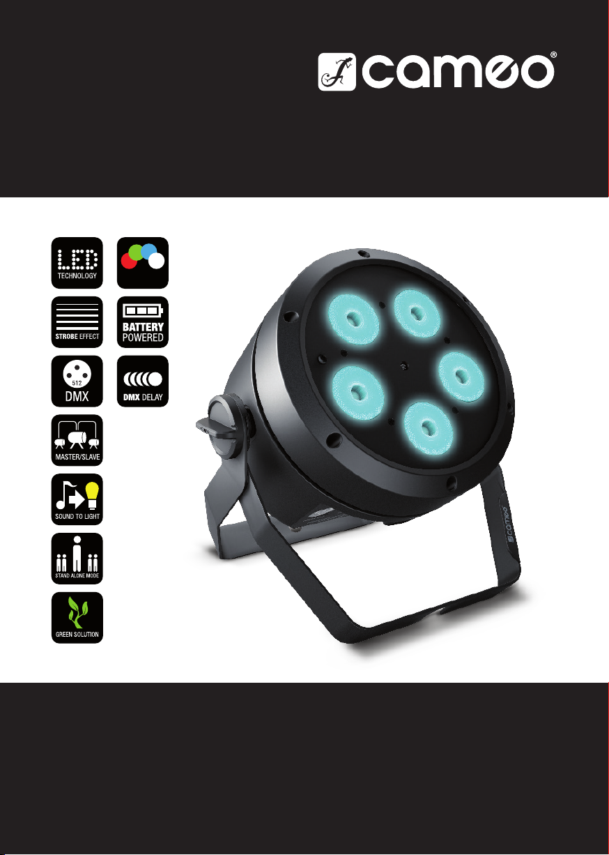
ROOT ® PAR BATTERY
5 × 4 W RGBW LED PAR SPOTLIGHT
CLROOTPARBAT

CONTENTS / INHALTSVERZEICHNIS / TABLE DES MATIÈRES / CONTENIDO /
SPIS TREŚCI / CONTENUTO
ENGLISH
INTENDED USE ........................................................................ 3
SAFETY INSTRUCTIONS ........................................................... 3
INFORMATION FOR PORTABLE INDOOR DEVICES ..................... 6
INTRODUCTION ....................................................................... 8
CONNECTIONS, OPERATING, AND DISPLAY ELEMENTS ............. 9
OPERATION ............................................................................. 11
IR REMOTE CONTROL (OPTIONAL) .......................................... 20
INSTALLATION AND MOUNTING ............................................... 21
CARE, MAINTENANCE, AND REPAIR ......................................... 23
DMX TECHNOLOGY ................................................................. 24
TECHNICAL SPECIFICATIONS ................................................... 26
DISPOSAL ............................................................................... 28
MANUFACTURER’S DECLARATIONS ......................................... 28
DEUTSCH
BESTIMMUNGSGEMÄSSER GEBRAUCH .................................... 29
SICHERHEITSHINWEISE ........................................................... 29
HINWEISE FÜR ORTSVERÄNDERLICHE INDOOR-GERÄTE ........... 33
EINFÜHRUNG ........................................................................... 34
ANSCHLÜSSE, BEDIEN- UND ANZEIGEELEMENTE ..................... 35
BEDIENUNG ............................................................................. 38
IR FERNBEDIENUNG (OPTIONAL) .............................................. 48
AUFSTELLUNG UND MONTAGE ................................................ 49
PFLEGE, WARTUNG UND REPARATUR ....................................... 51
DMX TECHNIK ......................................................................... 52
TECHNISCHE DATEN ................................................................ 54
ENTSORGUNG ......................................................................... 56
HERSTELLERERKLÄRUNGEN .................................................... 56
FRANÇAIS
UTILISATION PRÉVUE ............................................................... 57
CONSIGNES DE SÉCURITÉ ....................................................... 57
INFORMATIONS SUR LES APPAREILS PORTABLES
D’EXTÉRIEUR .......................................................................... 61
INTORDUCTION .......................................................................... 62
RACCORDEMENTS, ÉLÉMENTS DE COMMANDE ET
D’AFFICHAGE .......................................................................... 63
UTILISATION ............................................................................ 66
TÉLÉCOMMANDE INFRAROUGE (EN OPTION) ........................... 76
INSTALLATION ET MONTAGE ................................................... 77
ENTRETIEN, MAINTENANCE ET RÉPARATION ............................ 79
TECHNIQUE DMX ..................................................................... 80
CARACTÉRISTIQUES TECHNIQUES ........................................... 82
MISE AU REBUT ...................................................................... 84
DÉCLARATIONS DU FABRICANT ............................................... 84
ESPAÑOL
USO PREVISTO ........................................................................ 85
INSTRUCCIONES DE SEGURIDAD ............................................. 85
INFORMACIÓN SOBRE DISPOSITIVOS PORTÁTILES
PARA EXTERIORES ................................................................... 89
INTRODUCCIÓN ....................................................................... 90
CONEXIONES, ELEMENTOS DE MANEJO Y ELEMENTOS
DE VISUALIZACIÓN .................................................................. 91
FUNCIONAMIENTO ................................................................... 94
MANDO A DISTANCIA POR INFRARROJOS (OPCIONAL) ............. 104
INSTALACIÓN Y MONTAJE ........................................................ 105
CUIDADO, MANTENIMIENTO Y REPARACIÓN ............................. 107
TECNOLOGÍA DMX ................................................................... 108
DATOS TÉCNICOS .................................................................... 110
ELIMINACIÓN .......................................................................... 112
DECLARACIONES DEL FABRICANTE ......................................... 112
POLSKI
PREZEZNACZENIEM ................................................................. 113
ZASADY BEZPIECZEŃSTWA ...................................................... 113
UWAGI DOTYCZĄCE PRZENOŚNEGO SPRZĘTU
WEWNĘTRZNEGO .................................................................... 117
WPROWADZENIE ..................................................................... 118
PRZYŁĄCZA, ELEMENTY OBSŁUGI I WSKAŹNIKI ....................... 119
OBSŁUGA ................................................................................ 122
PILOT ZDALNEGO STEROWANIA (OPCJONALNY) ...................... 131
USTAWIANIE I MONTAŻ ............................................................ 133
UTRZYMANIE, KONSERWACJA I NAPRAWY ............................... 134
TECHNIKA DMX ....................................................................... 136
DANE TECHNICZNE .................................................................. 138
UTYLIZACJA ............................................................................ 140
DEKLARACJE PRODUCENTA .................................................... 140
ITALIANO
UTILIZZO CONFORME .............................................................. 141
INDICAZIONE SULLA SICUREZZA .............................................. 141
AVVERTENZE PER DISPOSITIVI INDUSTRIALI PORTATILI ............ 145
INTRODUZIONE ....................................................................... 146
CONNETTORII, ELEMENTI DI COMANDO E DI VISUALIZZAZIONE . 147
UTILIZZO ................................................................................. 150
TELECOMANDO A INFRAROSSI (OPZIONALE) ............................ 160
INSTALLAZIONE E MONTAGGIO ................................................ 161
CURA, MANUTENZIONE E RIPARAZIONE ................................... 163
TECNOLOGIA DMX ................................................................... 164
DATI TECNICI ........................................................................... 166
SMALTIMENTO ........................................................................ 168
DICHIARAZIONI DEL PRODUTTORE ........................................... 168
DMX
DMX CONTROL / DMX STEUERUNG / COMMANDE DMX /
CONTROL DMX / STEROWANIE DMX / CONTROLLO DMX
........ 169
ENGLISH
YOU’VE MADE THE RIGHT CHOICE!
This device was developed and manufactured under high quality requirements to ensure smooth
operation for many years. Please read this user manual carefully to ensure you can quickly make
the best use of your new Cameo Light product. Further information about Cameo Light is available
on our website at WWW.CAMEOLIGHT.COM.
INTENDED USE
The product is a device for event technology!
The product has been specially developed for professional use in event technology and is not
suitable for use in a household setting!
Furthermore, this product is only intended for qualified users with expertise in event technology!
Use of the product contrary to the specified technical specifications and operating conditions is
considered improper!
Liability for damages or third-party damage to persons and property due to improper use is
excluded!
The product is not suitable for:
- use by persons (including children) with reduced physical, sensory, or mental capabilities or with
insufficient experience and knowledge.
- children (children must be instructed not to play with the device).
SAFETY INSTRUCTIONS
- To avoid possible damage, please carefully read and observe these instructions.
- Keep all information and instructions in a safe place.
- Observe all warnings. Do not remove any safety instructions or other information from the
device.
DEUTSCH ENGLISH
FRANCAIS
ESPAÑOLITALIANO POLSKI
TERMS AND SYMBOLS
1. DANGER: The word DANGER, possibly used in combination with a symbol, Indicates
a hazardous situation which, if not avoided, WILL result in death or serious injury.
2. WARNING: The word WARNING, possibly used in combination with a symbol, Indicates a
hazardous situation which, if not avoided, COULD result in death or serious injury.
3. CAUTION: The word CAUTION, possibly used in combination with a symbol, refers to
situations or conditions that can lead to injuries.
4. NOTICE: The word NOTICE, possibly used in combination with a symbol, Indicates information
considered important but not hazard related (EX: messages relating to equipment/property
damage).
DMX
3
DEUTSCHENGLISH
FRANCAIS
ESPAÑOL
POLSKI
This symbol indicates an electrical hazard.
This symbol indicates a general hazard.
This symbol indicates danger from hot surfaces.
This symbol indicates danger from intense light sources.
This symbol indicates additional information on the operation of the product.
DANGER:
1. Do not open the device or make any modifications to it.
2. If your device stops working properly, if liquids or objects have penetrated the inside
of the device, or if the device has been damaged in any other way, switch it off immediately and unplug it from the power outlet. Only authorized specialists may repair
this device.
3. The protective earth conductor for Class I appliances must be properly connected.
Never disconnect the protective earth conductor. Class II appliances do not have a
protective earth conductor.
4. Make sure that voltage-conducting cables are not kinked or otherwise mechanically
damaged.
5. Never bypass the device fuse.
ITALIANO
DMX
4
WARNING:
1. The device must not be used if there are obvious signs of damage to the device.
2. The device may only be installed in voltage-free state.
3. Do not operate the device if its power cord is damaged.
4. Only a qualified person may replace permanently connected power cords.
NOTICE:
1. Do not operate the device right after it has been subjected to strong temperature
fluctuations (e.g., after transport). Humidity and condensation may have damaged the
device. Only switch the device on once it has reached room temperature.
2. Make sure that the voltage and frequency of the power supply correspond to the
values specified on the device. If the device has a voltage selector, do not plug in
the device until it has been properly set up. Only use suitable power cords.

3. Simply pressing the On/Off switch on the device is not enough to entirely
disconnect the device from the power supply.
4. Make sure that the fuse used corresponds to the type shown on the device.
5. Make sure that suitable measures have been taken to prevent power surges
(e.g., lightning strike).
6. Observe the specified maximum output current on devices with a Power Out
connection. Ensure that the total power consumption of all devices connected to
the device does not exceed the specified value.
7. Replace plug-in power cords only with cords that are comparable to the originally
supplied cords. The cross-section must not fall below the cross-section of the
original cord.
DANGER:
1. Risk of suffocation! Plastic bags and small parts must be kept out of reach of persons
(including children) with reduced physical, sensory, or mental capabilities.
2. Fall hazard! Make sure that the device is securely installed and cannot fall down.
Only use suitable stands or mountings (especially for fixed installations). Make sure
that accessories are properly installed and secured. Ensure that applicable safety
regulations are observed when doing this.
WARNING:
1. Only use the device as properly intended.
2. Only operate the device with accessories recommended and provided by
the manufacturer.
3. Please observe the safety regulations in place in your country when installing
the device.
4. After the device is connected, check all cable paths to prevent any damage or
accidents (e.g., tripping hazards).
5. Please observe the specified minimum distances to materials with normal
flammability! Unless explicitly stated, the minimum distance is 0.98 ft.
6. Always observe the minimum distance to the illuminated surface to be read
on the device!
DEUTSCH ENGLISH
FRANCAIS
ESPAÑOLITALIANO POLSKI
CAUTION:
1. Moving components such as mounting brackets or other moving components may
become trapped.
2. In the case of devices with motor-driven components, there is a risk of being injured
by the moving device. Sudden device movements can lead to startle responses.
3. The device’s housing surface can get very hot during regular operation. Make sure
that unintentional contact with the housing cannot happen. Always allow the device to
cool sufficiently before disassembly, maintenance work, and charging, etc..
DMX
5

DEUTSCHENGLISH
FRANCAIS
ESPAÑOL
NOTICE:
1. Do not install or operate the device near heating elements, heat storage units, stoves,
or other sources of heat. Make sure that the device is always installed so that it is
adequately cooled and cannot overheat.
2. Do not put any sources of ignition (e.g., burning candles) near the device.
3. Ventilation slots must be kept uncovered, and fans must not be blocked.
4. Use the original packaging or packaging provided by the manufacturer for transport.
5. Avoid shaking or banging the device.
6. Observe the IP rating as well as the ambient conditions such as the specified temperature and humidity.
7. Devices can be subject to ongoing development. If information on operating conditions, output, or other device characteristics differs between the user manual and
device label, the information provided on the device always takes priority.
8. The device is not suitable for tropical climate zones and operation above 6561 ft
above sea level.
9. The device is not suitable for operation under marine conditions.
CAUTION! IMPORTANT INFORMATION ON LIGHT PRODUCTS!
1. Never look directly (not even briefly) into the light source.
2. Never look into the light source with optical devices (e.g., magnifying glasses).
3. Strobe effects can trigger epileptic seizures in susceptible individuals!
POLSKI
ITALIANO
DMX
6
4. A permanently installed light source is built into this luminaire and cannot be
replaced by the user. Please contact your distributor in case of a system failure.
INFORMATION FOR PORTABLE INDOOR DEVICES
1. Temporary operation! Event equipment is designed in general for temporary operation
only.
2. Continuous operation or permanent structural attachment, especially in outdoor
areas, can negatively impact functionality, as well as surfaces and seals, and can
lead to accelerated material fatigue.
BATTERY SAFETY
• Keep the spotlight with the battery installed away from excessive heat and direct
sunlight. Do not place it on or in heating devices, such as microwaves, ovens, or
radiators. Batteries may explode if overheated.
• Do not attempt to open the spotlight and change or modify the battery, do not insert
foreign objects into the battery, or do not immerse it in or let it come into contact with
water or other liquids. Failure to do so may result in fire, explosion, or other hazardous
situations.
• In the event of the spotlight becoming deformed or overheating due to a battery
malfunction during the charging process or during storage, immediately refrain from
using the device and contact an authorized service center. Further use of the device
may result in fire or an explosion.
• Do not put the spotlight into a fire, as it could explode. Damaged batteries may also
explode.
• Do not strike or puncture the spotlight, or place it under high pressure. Failure to do
so may cause a short circuit or overheating.
• Do not drop the spotlight. If the device is dropped, particularly onto a hard surface, the
internal battery may be damaged.
• If the battery life shortens significantly, please contact an authorized service center.
• Do not attempt to remove the battery, as this could cause damage to the device.
Please contact an authorized service center to exchange the battery.
CHARGING THE BATTERY, OPERATING, AND STORING THE SPOTLIGHT
• Connect the spotlight to the power supply in order to charge the internal battery. The
battery is charged both when it is switched on and when the spotlight is switched off.
• It takes approx. 2 hours to charge the battery from 0% to 100%.
• The electronic battery management system protects the battery from overcharge and
deep-discharge.
• Do not charge the spotlight’s battery at ambient temperatures below 0°C and above
40°C.
• Operation may only occur at an ambient temperature above 0°C and below 40°C.
• The storage temperature must be above 0°C and below 35°C.
• Fully recharge the battery immediately after discharge. Batteries that are not fully
charged lose capacity and have a shortened service life.
• Store the spotlight only with a fully charged battery.
• If the spotlight is not used for a longer period of time, completely recharge the battery
every 6 months.
• To extend the lifetime of the battery, it is recommended that the battery is recharged
as soon as possible and that it is not used until completely empty/fully de-energized.
• In cold environments, battery life may be shorter than expected.
• Store the spotlight in cool and dry conditions to ensure optimal storage conditions for
the battery.
DEUTSCH ENGLISH
FRANCAIS
ESPAÑOLITALIANO POLSKI
DMX
7

INTRODUCTION
BATTERY-POWERED SPOTLIGHT WITH 5 × 4 W RGBW LEDS
CLROOTPARBAT
CONTROL FUNCTIONS
DMX modes without DMX delay channel: 2-channel, 4-channel 1, 4-channel 2, 5-channel,
6-channel, and 9-channel DMX control
DEUTSCHENGLISH
DMX modes with DMX delay channel: 3-channel, 5-channel 1, 5-channel 2, 6-channel, 7-channel,
and 10-channel DMX control
Master/slave mode
Stand-alone functions
Control via IR remote control (remote control optionally available)
W-DMX connection possible with optional iDMX stick
FRANCAIS
PROPERTIES
5 × 4 W RGBW LEDs. 3-pin DMX connectors. Power Twist power connector, IN and OUT. Power supply-independent operation thanks to internal Li-ion battery. OLED display. Configurable
PWM frequency. Connection for iDMX stick. Convection cooling. Tilt screw. Removable stand and
mounting bracket for inconspicuous uplighting. 100–240 V AC operating voltage. Power consump-
ESPAÑOL
tion in mains operation and with simultaneous charging of the battery 75 W.
BATTERY LIFE
BATTERY LIFE WITH FULLY CHARGED BATTERY IN POWER MODE STANDARD (STD)
RGBW 100% approx. 5 h
POLSKI
R + G 100% approx. 8 h 30 min
G 100% approx. 12 h
BATTERY LIFE WITH FULLY CHARGED BATTERY IN ECO POWER MODE
RGBW 100% approx. 6 h 30 min
R + G 100% approx. 14 h
ITALIANO
G 100% approx. 20 h
The charging time is approx. 2 hours.
DMX
8

CONNECTIONS, OPERATING AND DISPLAY ELEMENTS
5
1
POWER IN
12
4
3
Blue Power Twist power input socket. Operating voltage: 100–240 V AC / 50–60 Hz. A suitable
power cable with Power Twist plug is included in the package contents.
2
POWER OUT
White Power Twist power output socket to supply power to additional Cameo spotlights (max. 8 A).
3
DMX IN
Male 3-pin XLR connector to connect a DMX control device (e.g., DMX console).
4
DMX OUT
Female 3-pin XLR connector to transmit the DMX control signal.
DEUTSCH ENGLISH
FRANCAIS
ESPAÑOLITALIANO POLSKI
5
iDMX
Connection for the optionally available iDMX stick for W-DMX™ connection.
6
FUSE
Fuse holder for 5 × 20 mm micro fuses. IMPORTANT NOTE: Only replace the fuse with a fuse of
the same type and values. If a fuse trips repeatedly, please contact an authorized service center.
7
POWER
Push switch for switching the spotlight on and off.
DMX
9

DEUTSCHENGLISH
12
7
11
12
13
6
12
FRANCAIS
10
8
9
12
ESPAÑOL
8
OLED-DISPLAY
The OLED display shows the currently activated mode (main display), the menu options in the
POLSKI
Options menu, and the numerical values or operating status for certain menu options . If there is
no input within approx. two minutes, the information in the display automatically switches to the
main display. Note on the main display in operating modes with external control: As soon as the
control signal is interrupted, the symbols on the display will begin to flash. When the control signal
is present again, the flashing will stop. Starting from the main display, briefly press the button
to rotate the information in the display 180°.
ITALIANO
9
CONTROL BUTTONS
MENU – you can access the options menu by pressing MENU. Pressing it again will return you
to the main display. If you press MENU without having first pressed ENTER to confirm a value or
status change, the previously confirmed value or status shall be restored.
ENTER – pressing ENTER takes you to the menu level, where value changes can be made, and
DMX
you can reach the submenu using ENTER. Value or status adjustments can also by confirmed
by pressing ENTER. and – these select the individual menu options in the selection menu
(DMX address, mode, etc.) and in the submenus. They allow you to change the value of a menu
option (e.g., DMX address) as desired.
10

10
MIC
Microphone for music control mode.
11
TILT
Knurled screw for tilting when used as uplight. The twin mounting bracket can be removed for a
more subtle look.
12
RUBBER FEET
Four rubber feet for stability.
13
SAFETY EYEBOLT
Safety eyebolt for securing the spotlight on crossbeam installations.
DEUTSCH ENGLISH
OPERATION
NOTES
• After the spotlight is switched on, “Welcome to Cameo,” the model name, and the software version are shown one after the other on the display during the start-up process. Once the process
is complete, the spotlight is ready for use and resumes whichever mode was most recently
activated.
• Hold down the MENU button for approx. 2 seconds to directly access the main display from the
lower menu levels. If there is no input within approx. two minutes, the main display is automatically activated. Briefly press MENU to go up one level in the submenus.
• Press MENU and ENTER at the same time to go directly to the last edited menu option.
• Starting from the main display, briefly press the button to rotate the information in the
display 180°.
• To quickly change a value (e.g., DMX start address), hold down the or button.
• If the internal battery is charged while the spotlight is switched off, the battery symbol
appears in the middle of the display and the charging status is shown by the corresponding
segment flashing. The flashing stops once the battery is fully charged.
MAIN DISPLAY DMX MODE
The DMX address and the currently configured DMX start address (e.g., 001) are shown on
the display. If the DMX Delay function is activated, the delay group and the delay time are also
displayed. The battery’s charging status is shown in five segments in the upper-right corner of the
display. When the spotlight is operated with a supply voltage, the internal battery is charged at the
same time and a lightning symbol appears next to the battery symbol.
FRANCAIS
ESPAÑOLITALIANO POLSKI
DMX
11

MAIN DISPLAY STAND-ALONE MODE
The display shows the currently activated stand-alone mode (Mode Auto, Mode Sound, Mode
Static, Mode Color Preset, Mode User Color, Mode Loop). The battery’s charging status is shown
in five segments in the upper-right corner of the display. When the spotlight is operated with a
DEUTSCHENGLISH
supply voltage, the internal battery is charged at the same time and a lightning symbol appears
next to the battery symbol.
MAIN DISPLAY SLAVE MODE
FRANCAIS
Mode Slave is shown on the display. If the slave unit is assigned to a slave group, the slave
group and delay time set on the master unit in the stand-alone modes Auto and Loop are also
displayed. The battery’s charging status is shown in five segments in the upper-right corner of the
display. When the spotlight is operated with a supply voltage, the internal battery is charged at the
same time and a lightning symbol appears next to the battery symbol.
ESPAÑOL
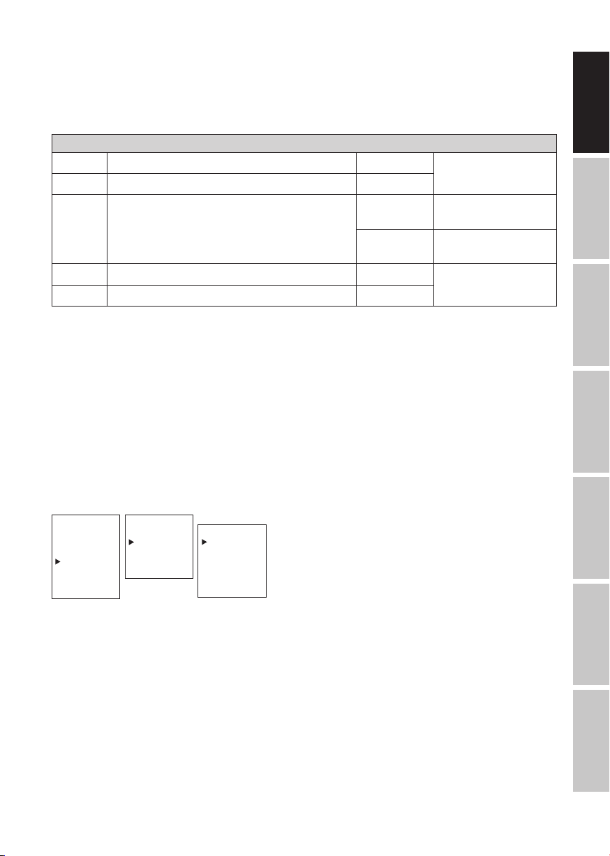
CONFIGURING THE DMX START ADDRESS
You can access the main menu by pressing MENU. Using the and buttons, now select the
DMX Address menu option and press ENTER to confirm your selection. You can now set the DMX
POLSKI
start address as desired using and . Press enter to confirm your selection and then press
MENU once to return to the main screen. If there is no input within approx. two minutes, the main
display is automatically activated.
ITALIANO
--------Menu------DMX Address
DMX Mode
DMX Delay
Stand Alone
Slave
Settings
System Info
----DMX Address---DMX Address
001–512
DMX Mode
DMX Delay
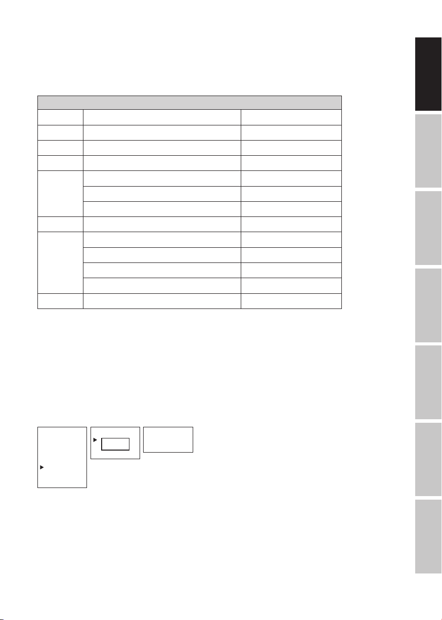
SETTING DMX MODE
You can access the main menu by pressing MENU. Using the and buttons, now select the
DMX
DMX Mode menu option and press ENTER to confirm your selection. Use and again to
select the desired DMX mode and press ENTER to confirm your selection (DMX operating modes
with DMX delay channel are labeled with “D”). Press MENU once to return to the main screen. If
there is no input within approx. two minutes, the main display is automatically activated. You can
12
find tables on channel assignment in the different DMX modes in these instructions under DMX
CONTROL.
--------Menu------DMX Address
DMX Mode
DMX Delay
Stand Alone
Slave
Settings
System Info
----DMX Address---DMX Address
2CH
001–512001–512001–512
DMX Mode
4CH1
DMX Delay
4CH2
5CH
6CH
9CH
D3CH
D5CH1
D5CH2
D6CH
D7CH
D10CH
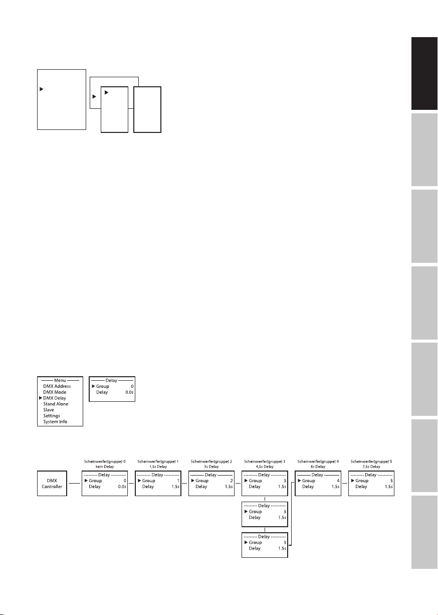
DMX DELAY
The DMX Delay function allows a chaser light effect to be easily created with any number of
spotlights of the same model and software version, which could otherwise only be achieved with
a suitable DMX controller and complex programming. All spotlights integrated into the setup are
set to the same DMX mode and controlled with the same DMX start address.
Manually set the DMX delay for DMX operating modes without DMX delay channel (2CH,
4CH1, 4CH2, 5CH, 6CH, 9CH):
Starting from the main display, press MENU to go to the main menu. Using the and buttons,
now select the DMX Delay menu option and press ENTER to confirm your selection. Use and
again to select the desired submenu item, press ENTER to confirm, and set the corresponding
value as desired. Press ENTER to confirm all entries.
Assign the spotlight to one of 47 groups (maximum number of groups depends on the activated
DMX mode). Several spotlights can also be assigned to one group. The group number is also the
factor by which the set delay time is multiplied.
The delay time (delay time of the DMX signal) can be set manually on each spotlight separately
with different values (0.0 s to 2.0 s in 0.1 s steps).
Setup example:
DEUTSCH ENGLISH
FRANCAIS
ESPAÑOLITALIANO POLSKI
13
DMX

Set the DMX delay for DMX operating modes with DMX delay channel (D3CH, D5CH1,
D5CH2, D6CH, D7CH, D10CH):
Starting from the main display, press MENU to go to the main menu. Using the and buttons,
now select the DMX Delay menu option and press ENTER twice to confirm your selection.
Assign the spotlight to one of 47 groups (maximum number of groups depends on the activated
DMX mode). Several spotlights can also be assigned to one group. The group number is also the
factor by which the set delay time is multiplied. Confirm each entry with ENTER.
DEUTSCHENGLISH
The delay time (delay time of the DMX signal) is set using a DMX controller in the separate DMX
FRANCAIS
delay channel of the corresponding DMX operating mode (0.0 s to 2.0 s in 0.1 s steps).
Setup example:
ESPAÑOL
POLSKI
STANDALONE MODE AUTO / SOUND
The 6 available Auto programs each consist of preprogrammed color change sequences; brightness, operating speed, music control with microphone sensitivity, and delay (signal delay) are
configured separately for each program.
Starting from the main display, press MENU to go to the main menu. Using the and buttons,
ITALIANO
now select the Stand Alone menu option and press ENTER to confirm your selection. Use
and again to select the stand-alone mode Auto and press ENTER to confirm your selection.
Now use and to select the desired program (Program 1 to Program 6) and press ENTER to
confirm your selection.
DMX
--------Menu------DMX Address
DMX Mode
DMX Delay
Stand Alone
Slave
Settings
System Info
----Stand Alone---Auto
Static
Color Preset
User Color
Loop
----Auto Mode---Program 1
|
Program 6
-----Program x----Dimmer
0–100
Speed
0–100
Sound
Off/On
Sens
0–100
Delay
0.0 s to 2.0 s
14
This will take you to the submenu for setting the submenu options (see table, use and to
select, press ENTER to confirm, use and to change the value or status, press ENTER to
confirm). The settings are made separately for each program and remain unchanged even after
the device is restarted.
STANDALONE MODE AUTO / SOUND (PROGRAMME 1 to PROGRAMME 6)
Dimmer Sets brightness 0 - 100
Speed Sets running speed 0 - 100
Sound
Activates/deactivates music-control
Off
On
Deactivates
music-control
Activates
music-control
Sens Sets microphone sensitivity 0 - 100
Delay Delay time for slave groups 0.0s - 2.0s
STANDALONE MODE STATIC
The standalone mode static allows the dimmer, strobe, R, G, B and W values to be set directly on
the device, with values between 000 and 255, in a similar way to with a DMX controller. In this
way, an individual scene can be created without an additional DMX controller.
Starting from the main display, press MENU to enter the main menu. Now use and to select
the menu item Stand Alone
and confirm with ENTER. Again use and to select standalone
mode Static and confirm with ENTER. Using and , now select the menu item that you wish
to edit and confirm with ENTER. You can use and to configure the desired value between
000 and 255. Confirm all entries with ENTER.
DEUTSCH ENGLISH
FRANCAIS
ESPAÑOLITALIANO POLSKI
--------Menu------DMX Address
DMX Mode
DMX Delay
Stand Alone
Slave
Settings
System Info
----Stand Alone---Auto
Static
Color Preset
User Color
Loop
----Static Mode---Dimmer
0 - 255
Strobe
0 - 255
Red
0 - 255
Green
0 - 255
Blue
0 - 255
White
0 - 255
COLOR PRESET STAND-ALONE MODE
15 different color presets plus Jump and Fade are available as presets; the brightness can be
configured separately for each preset, as well as the operating speed for Jump and Fade.
Starting from the main display, press MENU to go to the main menu. Using the and but-
tons, now select the Stand Alone menu option and press ENTER to confirm. Use and again
to select the stand-alone mode Color Preset and press ENTER to confirm your selection. Now
use and to select the color you want as a preset and press ENTER to confirm your selection
(Off = Blackout; Speed refers to Jump and Fade). You can set the brightness as desired from 000
to 100 using and . Confirm with ENTER.
DMX
15

--------Menu------DMX Address
DMX Mode
DMX Delay
Stand Alone
Slave
Settings
System Info
DEUTSCHENGLISH
USER COLOR STAND-ALONE MODE
----Stand Alone---Auto
Static
Color Preset
User Color
Loop
----Color Preset---Off
Red
0 - 100
Amber
0 - 100
Yel Warm
0 - 100
Yellow
0 - 100
Green
0 - 100
Turquoise
0 - 100
Cyan
Blue
Lavender
Mauve
Magenta
Pink
Warm White
0 - 100
0 - 100
0 - 100
0 - 100
0 - 100
0 - 100
0 - 100
White
0 - 100
Cold White
0 - 100
Jump
0 - 100
Fade
0 - 100
Speed
0 - 100
The stand-alone mode User Color makes it possible to save the overall brightness, strobe, and
a color mix of R, G, B, and W to four individual color presets directly on the device.
Starting from the main display, press MENU to go to the main menu. Using the and
buttons, now select the Stand Alone menu option and press ENTER to confirm your selection.
Use and again to select the stand-alone mode UserColor and press ENTER to confirm
FRANCAIS
your selection. Now use and to select the desired preset (Color 1 to Color 4) and press
ENTER to confirm. Now use and to select the menu option you would like to change and
press ENTER to confirm your selection. You can set the value as desired from 000 to 255 using
and . The strobe effect values correspond to the values in channel 2 of the DMX table 4 CH
mode1. Press ENTER to confirm all entries.
--------Menu-------
ESPAÑOL
POLSKI
DMX Address
DMX Mode
DMX Delay
Stand Alone
Slave
Settings
System Info
LOOP STAND-ALONE MODE
----Stand Alone---Auto
Static
Color Preset
User Color
Loop
----User Color---Color 1
|
Color 4
-------Color x------Dimmer
0 - 255
Strobe
0 - 255
Red
0 - 255
Green
0 - 255
Blue
0 - 255
White
0 - 255
The stand-alone Loop mode allows up to four different color change programs to be individually
designed, saved, and reproduced. Brightness, step time, fade time, and delay (signal delay) can
be set separately.
Starting from the main display, press MENU to go to the main menu. Using the and
buttons, now select the Stand Alone menu option and press ENTER to confirm your selection.
Use and again to select the stand-alone mode Loop and press ENTER to confirm your
ITALIANO
selection. Now use and to select the desired loop (Loop 1 to Loop 4) and press ENTER to
confirm your selection.
DMX
--------Menu------DMX Address
DMX Mode
DMX Delay
Stand Alone
Slave
Settings
System Info
----Stand Alone---Auto
Static
Color Preset
User Color
Loop
----Loop Mode---Loop 1
|
Loop 4
---------Loop x--------Dimmer
Steptime
Fadetime
Delay
1.Step
2.Step
3.Step
4.Step
0 - 100
0.1s - 10.0s
0 % - 100 %
0.0s - 2.0s
Red
Green
Black
-------
16
This will take you to the submenu for setting the submenu options (see table, use and to
select, press ENTER to confirm, use and to change the value or status, press ENTER to
confirm). The settings are made separately for each loop and are retained even after restarting the
device.
STANDALONE MODE LOOP (Loop 1–4)
Dimmer Sets brightness 0–100
Step time Sets step time 0.1 s to 10.0 s
Fade time Sets fade time in percent 0% to 100%
Delay Delay time for slave groups 0.0 s to 2.0 s
1st step 15 colors from Color Preset Red to CW (Cold White)
4 colors from User Color User 1 to User 4
Blackout Blackout
2nd step " "
15 colors from Color Preset Red to CW (Cold White)
3rd step
4 colors from User Color User 1 to User 4
Blackout Blackout
------- Skip step
4th step " "
DEUTSCH ENGLISH
FRANCAIS
ESPAÑOLITALIANO POLSKI
SLAVE MODE
Standard Slave mode: Starting from the main display, press MENU to go to the main menu.
Using the and buttons, now select the Slave menu option, press ENTER to confirm your
selection, then select Slave Group 0, and press enter once again to confirm. Connect the slave
and master unit (same model, same software version) using a DMX cable, and activate one of the
stand-alone modes on the master unit (Auto, Static, Color Preset, User Color, Loop). The slave unit
will now follow the master unit precisely.
--------Menu------DMX Address
DMX Mode
DMX Delay
Stand Alone
Slave
Settings
System Info
----Slave Group---Stand Alone
0
Slave
Settings
Mode
Slave
Main display
Advanced slave mode: If you want to control the slave units in master/slave mode using
one of the stand-alone modes Auto or Loop, the control signal can be reproduced with a time
delay of up to 15 levels. The delay time can be set in the Delay submenu option in the respective
stand-alone mode, and the delay factor for the corresponding slave unit can be set in the slave
menu. This allows a chaser light effect to be easily created with any number of spotlights of the
DMX
17

same model and software version, which could otherwise only be achieved with a suitable DMX
controller and complex programming.
DEUTSCHENGLISH
--------Menu------DMX Address
DMX Mode
DMX Delay
Stand Alone
Slave
Settings
System Info
----Slave Group---Stand Alone
1 - 15
Slave
Settings
Mode
Slave
Gr 1 2.0s
Main display
with group number
and delay time in the
master unit
Assign the spotlight to one of 15 groups as you like. Several spotlights can also be assigned to
one group. The group number is also the factor by which the set delay time on the master unit is
multiplied (see setup example).
FRANCAIS
ESPAÑOL
Master unit
Auto program 1
Delay 0.5 s
Slave Group 0
No delay
Mode
Slave
Slave Group 1
0.5s
delay
Mode
Slave
Gr 1 0.5s Gr 2 0.5s Gr 3 0.5s
Slave Group 2
1s
delay
Mode
Slave
Slave Group 3
1.5s
delay
Mode
Slave
Mode
Slave
Gr 3 0.5s
Mode
Slave
Gr 3 0.5s
Slave Group 4
2s
delay
Mode
Slave
Gr 4 0.5s Gr 5 0.5s
SYSTEM SETTINGS (Settings)
POLSKI
Starting from the main display, press MENU to go to the main menu. Using the and buttons,
now select the Settings menu option and press ENTER to confirm your selection.
Slave Group 5
2.5s
delay
Mode
Slave
--------Menu------DMX Address
DMX Mode
DMX Delay
Stand Alone
ITALIANO
Slave
Settings
System Info
This will take you to the submenu for setting the submenu options (see table, use and to
select, press ENTER to confirm, use and to change the value or status, press ENTER to
confirm).
DMX
Settings
Disp Rev = Rotates display No Display does not rotate
Yes Display rotates 180° (e.g., for overhead
installation)
18

Disp Back = Display backlight Off Deactivates after approx. 30 seconds of
inactivity
On Permanently on
Sig Fail = Operating status if
DMX signal is lost
Master/Slave?
Power Mode = Battery life and
LED brightness
setting
IR Remote = Activates or deac-
tivates control via
IR remote control
Sound = Adjusts the way
the music control
works
PWM = LED PWM
frequency
Calibration = Color calibration Red, Green,
Reset = Resets settings Factory Resets to factory settings: Press ENTER
Edit Preset = Saves all system
settings in 3 individual presets
Service = Only for servicing purposes
Hold Last command is held
Black Activates blackout
User 1 User Color 1 is activated
STD Standard setting with maximum
brightness
ECO Extended battery life at approx. 50%
brightness
On Activates control via the IR remote
Off
Last Color is kept until next pulse
Off Color disappears after a short while
650 Hz,
1530 Hz,
2150 Hz,
4000 Hz
Blue, White
Preset A Resets to Preset A: Press ENTER to
Preset B Resets to Preset B: Press ENTER to
Preset C Resets to Preset C: Press ENTER to
Preset A Press ENTER to save
Preset B Press ENTER to save
Preset C Press ENTER to save
Deactivates control via the IR remote
until the next pulse
Selects the LED PWM frequency
Individual color calibration. Cross-mode
brightness setting of the 4 LED groups
RGBW with values from 0–255
to reset, MENU to cancel
reset, MENU to cancel
reset, MENU to cancel
reset, MENU to cancel
DEUTSCH ENGLISH
FRANCAIS
ESPAÑOLITALIANO POLSKI
SYSTEM INFORMATIONEN (System Info)
Starting from the main display, press MENU to go to the main menu. Using and , now select
the System Info menu option and press EENTER to confirm your selection.
DMX
19

--------Menu------DMX Address
DMX Mode
DMX Delay
Stand Alone
Slave
Settings
System Info
This will take you to the submenu which will let you access system information (see table, use
and to select, press ENTER to confirm, use and to change status, press ENTER to
DEUTSCHENGLISH
confirm).
System Info
Firmware = Displays the
FRANCAIS
Temperature
Op Hours = Displays
device firmware
= Displays tem-
perature of the
LED unit
operating time
Firmware
V1.xx
LED xxx°C / xxx°F
Unit °C (= displays in degrees Celsius)
°F (= displays in degrees Fahrenheit)
xx:xxh Displays the total operating time in hours
and minutes
ESPAÑOL
IR REMOTE CONTROL (optional)
Aim the infrared remote control directly, within line-ofsight, at the infrared sensor installed on the front side of
the spotlight. The maximum range is approx. 8 meters. The
POLSKI
spotlight’s sensor is deactivated in DMX and slave mode.
The infrared remote control directly controls the internal
stand-alone modes Auto / Sound, Static, and Color
Preset.
BL / ON/OFF (Blackout)
The BL (Blackout) button switches off all LEDs, regardless
ITALIANO
of which mode is activated via the remote control. Press the
BL button again to reactivate the previously selected mode.
SP (Speed)
6-speed setting for the color change programs: Color Jumping (Ju), Color Fading (Fa), and Auto Program (Au). Level
1 allows the color change sequence to progress slowly,
DMX
pressing it again activates level 2 with a faster change sequence, and this is followed by levels 3,
4, 5, and 6, where level 6 is the fastest sequence of color changes.
20

(Brightness)
Set the overall brightness in 6 steps. Press this button several times (Step 1 = blackout) to access
the different brightness levels.
FL (Flash/Strobe)
Speed setting for the strobe effect in 6 steps. Step 1 deactivates the strobe effect, step 2 produces a slow frequency followed by steps 3 to 5. Step 6 produces the fastest flash frequency. The
strobe effect can only be used in RGBW color mixing mode.
R / G / B / W
Individual color mixes can be created using these 4 buttons. The 6 brightness levels can be
accessed by pressing the respective color button again, where level 1 means that the LEDs are
switched off. Example: If you set red and green to their respective maximum levels and the other
LEDs to their lowest (off), then you will have a color mix of light yellow.
Ju (Color change)
The color changes rapidly (color jumping). The color-changing speed can be set with the SP
button (Speed).
Fa (Fade)
Colors fade into each other (color fading). The color-changing speed can be set with the SP button
(Speed).
DEUTSCH ENGLISH
FRANCAIS
Au (Automatic mode)
Repeatedly press the Au button to select the desired color change program Auto 1–6.
Su (Music-controlled color change programs)
Repeatedly press the Su button to select one of the 6 music-controlled programs Sound 1–6. The
control microphone is located on the back of the spotlight.
CM (Color macros)
Use the CM+ and CM- buttons to successively access fifteen color presets.
Pr+/Pr-
Select programs in automatic mode (Au) and in music control (Su).
INSTALLATION AND MOUNTNG
Thanks to its convenient double bracket, the lamp can be positioned in a suitable location on a
level surface. Installation on a traverse is possible with a traverse clamp, which is attached to the
mounting bracket (A). Suitable traverse clamps are optionally available. Ensure firm connections
and secure the spotlight by attaching a suitable safety cable to the securing lug on the back of the
spotlight.
ESPAÑOLITALIANO POLSKI
DMX
21

DEUTSCHENGLISH
DANGER: Overhead installation requires extensive experience, including the calculation
of the load limit values of the installation material and regular safety inspection of all
installation materials and spotlights. If you do not have these qualifications, do not
attempt to carry out the installation yourself; contact a professional company. There is a
risk that incorrectly mounted or secured devices may come loose and fall down. This
may lead to serious injury and even fatalities.
B
FRANCAIS
ESPAÑOL
A
To create a more discrete look when using as an uplight, the double mounting bracket can be
POLSKI
removed by releasing both handle screws (B).
ITALIANO
B
DMX
22

CARE, MAINTENANCE, AND REPAIR
The device must be maintained and serviced regularly, at least every 3,000 operating hours or
at the latest after one year, in order to ensure that it continues to operate properly over the long
term.
CARE (user executable)
WARNING! The power supply and, if possible, all device connections must be
disconnected before carrying out any care/maintenance measures.
NOTE! Improper care can lead to damage to the device or even destruction.
1. Housing surfaces must be cleaned with a clean, damp cloth. Make sure that no moisture can
penetrate the device.
2. Dust and dirt must be regularly removed from air inlets and outlets. If compressed air is used,
care must be taken to prevent damage to the device (e.g., fans must be blocked in this case;
otherwise they might overwind).
3. Cables and plug-in contacts must be cleaned regularly and dust and dirt must be removed.
4. In general, no cleaning agents or abrasive agents may be used to care for the device as this
could have a negative impact on the surface finish.
5. In general, devices must be stored in a dry place and protected from dust and dirt.
6. All accessible or removable lenses and light emitting apertures must be cleaned on a regular
basis to ensure proper and safe operation.
MAINTENANCE AND REPAIR (by specialists only)
DANGER! The device contains voltage-conducting components. There may still be
residual voltage in the device even after it is disconnected from the power supply (e.g.,
due to charged capacitors).
NOTE! The device contains no user-serviceable components.
NOTE! Maintenance and repair work may only be carried out by sufficiently qualified specialists. In
case of doubt, consult a specialist workshop.
DEUTSCH ENGLISH
FRANCAIS
ESPAÑOLITALIANO POLSKI
NOTE! Improperly carried out maintenance work can affect the warranty claim.
NOTE! Please observe the enclosed installation guide when upgrading or retrofitting kits provided
by the manufacturer.
DMX
23

DMX TECHNOLOGY
DMX-512
DMX (Digital Multiplex) is the designation for a universal transmission protocol for communications between corresponding devices and controllers. A DMX controller sends DMX data to the
connected DMX device(s). The DMX data is always transmitted as a serial data stream that is
forwarded from one connected device to the next via the “DMX IN” and “DMX OUT” connectors
(XLR plug-type connectors) that are found on every DMX-capable device, provided the maximum
DEUTSCHENGLISH
number of devices does not exceed 32 units. The last device in the chain needs to be equipped
with a terminator (terminating resistor).
DMX CONNECTION
DMX is the common “language” via which a very wide range of types and models of equipment
from various manufacturers can be connected with one another and controlled via a central
FRANCAIS
controller, provided that all of the devices and the controller are DMX compatible. For optimum
data transmission, it is necessary to keep the connecting cables between the individual devices
as short as possible. The order in which the devices are integrated in the DMX network has no
influence on the addresses. Thus the device with the DMX address 1 can be located at any position in the (serial) DMX chain: at the beginning, at the end or somewhere in the middle. If the DMX
address 1 is assigned to a device, the controller “knows” that it should send all data allocated to
address 1 to this device regardless of its position in the DMX network.
ESPAÑOL
SERIAL CONNECTION OF MULTIPLE LIGHTS
1.
Connect the male XLR connector (3-pin or 5-pin) of the DMX cable to the DMX output (female
XLR socket) of the first DMX device (e.g. DMX-Controller).
2. Connect the female 3-pin XLR connector of the DMX cable connected to the first projector to
POLSKI
the DMX input (male 3-pin socket) of the next DMX device. In the same way, connect the DMX
output of this device to the DMX input of the next device and repeat until all devices have been
connected. Please note that as a rule, DMX devices are connected in series and connections
cannot be shared without active splitters. The maximum number of DMX devices in a DMX
chain should not exceed 32 units.
The Adam Hall 3 STAR, 4 STAR, and 5 STAR product ranges include an extensive selection of
ITALIANO
suitable cables.
DMX CABLES
When fabricating your own cables, always observe the illustrations on this page. Never connect
the shielding of the cable to the ground contact of the plug, and always make certain that the
shielding does not come into contact with the housing of the XLR plug. If the shielding is connected to the ground, this can lead to short-circuiting and system malfunctions.
DMX
24

PIN ASSIGNMENT
DMX cable with 3-pin XLR connectors: DMX cable with 5-pin XLR connectors
(pin 4 and 5 are not used):
1
3
2
Shield
1
3
2
5
4
3
2
1
Shield
5
4
3
2
1
DMX TERMINATORS (TERMINATING RESISTORS)
To prevent system errors, the last device in a DMX chain needs to be equipped with a terminating
resistor (120 ohm, 1/4 Watt).
3-pin XLR connector with a terminating resistor: K3DMXT3
5-pin XLR connector with a terminating resistor: K3DMXT5
PIN ASSIGNMENT
3-pin XLR connector: 5-pin XLR connector:
1
3
2
5
4
3
2
1
DMX ADAPTER
The combination of DMX devices with 3-pin connectors and DMX devices with 5-pin connectors
in a DMX chain is possible with suitable adapters.
PIN ASSIGNMENT
DMX Adapter 5-pin XLR male to 3-pin XLR female:
K3DGF0020
Pins 4 and 5 are not used.
DEUTSCH ENGLISH
FRANCAIS
ESPAÑOLITALIANO POLSKI
PIN ASSIGNMENT
DMX Adapter 3-pin XLR male to 5-pin XLR female:
K3DHM0020
Pins 4 and 5 are not used.
DMX
25

TECHNICAL SPECIFICATIONS
ARTICLE NUMBER: CLROOTPARBAT
Product type: LED battery spotlight
Type: PAR spotlight
Color spectrum: RGBW
Number of LEDs: 5
DEUTSCHENGLISH
LED type: 4 W
LED PWM frequency: 650 Hz, 1530 Hz, 2150 Hz, 4000 Hz (adjustable)
Beam angle (half peak
angle):
DMX input: 3-pin male
FRANCAIS
DMX output: 3-pin female
DMX modes: Without DMX delay channel: 2-channel, 4-channel 1, 4-channel 2,
DMX functions: dimmer, fine dimmer, strobe, red, green, blue, white, color macros,
ESPAÑOL
Controller: DMX512, IR remote control, W-DMX (via optional iDMX stick)
Stand-alone functions: auto programs, sound programs, static, color presets, user colors, loop
Control elements: Mode, Enter, Up, Down
Display elements: OLED display
POLSKI
Operating voltage: 100–240 V AC / 50–60 Hz
Power consumption
(max.):
Illumination intensity
(@1 m/@3 m):
ITALIANO
Luminous flux: 1000 lm
Power supply connec-
tion:
Electrical protection
class (IP):
Fuse: F3A / 250 V (5 × 20 mm)
DMX
Battery: Li-Ion / 4400 mAH / 22.2 V / 97.7 Wh
Ambient temperature
(in operation):
33° (20°)
5-channel, 6-channel, 9-channel
With DMX delay channel: 3-channel, 5-channel 1, 5-channel 2,
6-channel, 7-channel, 10-channel
running light selection, DMX delay, microphone sensitivity
function
75 W (when ALL LED @FULL ON and battery is charged)
24 W when battery is full and ALL LED @FULL ON
8000 lx / 806 lx
INPUT: Blue Power Twist power socket
OUTPUT: White Power Twist power socket (max. 8 A)
1
0°C to 40°C
26

ARTICLE NUMBER: CLROOTPARBAT
Relative humidity: < 75%, non-condensing
IP rating: IP20
Housing color: Black
Housing material: ABS plastic
Housing cooling: Convection cooling
Dimensions
(W × H × D, without
mounting bracket):
Weight (incl. mounting
bracket):
Additional features: Power cable included in the package contents and IR remote control
195 × 156 × 195 mm
2.5 kg
available as optional accessory (CLPFLAT1REMOTE). iDMX stick for
W-DMX™ connection optionally available (CLIDMXSTICK)
DEUTSCH ENGLISH
FRANCAIS
ESPAÑOLITALIANO POLSKI
27
DMX

DISPOSAL
Packaging
1. Packaging can be recycled using the usual disposal methods.
2. Please separate packaging in accordance with the disposal laws and recycling
regulations in your country.
DEUTSCHENGLISH
FRANCAIS
ESPAÑOL
MANUFACTURER’S DECLARATIONS
MANUFACTURER’S WARRANTY AND LIMITATION OF LIABILITY
Adam Hall GmbH, Adam-Hall-Str. 1, D-61267 Neu Anspach, Germany / Email Info@adamhall.com /
+49 (0)6081 / 9419-0.
Our currently valid warranty conditions and limitation of liability are available at:
https://cdn-shop.adamhall.com/media/pdf/Manufacturers-Declarations-CAMEO_DE_EN_ES_FR.pdf.
POLSKI
Please contact your distributor when servicing is required.
CE CONFORMITY
Adam Hall GmbH hereby declares that this product complies with the following guidelines
(where applicable):
R&TTE (1999/5/EG) or RED (2014/53/EU) as of June 2017
Low-Voltage Directive (2014/35/EU)
ITALIANO
EMC Directive (2014/30/EU)
RoHS (2011/65/EU)
The full declaration of conformity can be found at www.adamhall.com.
It can also be requested from info@adamhall.com.
Device:
1. This device is subject to the European Community Directive on waste electrical and
electronic equipment (WEEE) in the currently applicable version. WEEE Directive Waste
Electrical and Electronic Equipment. Waste equipment does not belong in household
waste. Waste equipment must be disposed by a registered waste disposal company
or at a municipal disposal facility. Please observe the applicable regulations in your
country!
2. Observe all waste disposal laws applicable in your country.
3. Private customers can contact the distributor/retailer from whom the product was
purchased or the relevant local authorities to obtain information on environmentally
friendly waste management
DMX
SUBJECT TO PRINTING ERRORS AND MISTAKES, AS WELL AS TECHNICAL OR OTHER
CHANGES!
28

DEUTSCH
SIE HABEN DIE RICHTIGE WAHL GETROFFEN!
Dieses Gerät wurde unter hohen Qualitätsanforderungen entwickelt und gefertigt, um viele Jahre
einen reibungslosen Betrieb zu gewährleisten. Bitte lesen Sie diese Bedienungsanleitung sorgfältig, damit Sie Ihr neues Produkt von Cameo Light schnell und optimal einsetzen können. Weitere
Informationen über Cameo Light erhalten Sie auf unserer Website WWW.CAMEOLIGHT.COM.
BESTIMMUNGSGEMÄSSER GEBRAUCH
Bei dem Produkt handelt es sich um ein Gerät für die Veranstaltungstechnik!
Das Produkt ist für den professionellen Einsatz im Bereich der Veranstaltungstechnik entwickelt
worden und ist nicht für die Verwendung in Haushalten geeignet!
Weiterhin ist dieses Produkt nur für qualifizierte Benutzer mit Fachkenntnissen im Umgang mit
Veranstaltungstechnik vorgesehen!
Die Benutzung des Produkts außerhalb der spezifizierten technischen Daten und Betriebsbedingungen gilt als nicht bestimmungsgemäß!
Haftung für Schäden und Drittschäden an Personen und Sachen durch nicht bestimmungsgemäßen Gebrauch ist ausgeschlossen!
Das Produkt ist nicht geeignet für:
- Personen (einschließlich Kinder) mit eingeschränkten körperlichen, sensorischen oder geistigen
Fähigkeiten oder mangelnder Erfahrung und Kenntnis.
- Kinder (Kinder müssen angewiesen werden, nicht mit dem Gerät zu spielen).
DEUTSCH ENGLISH
FRANCAIS
ESPAÑOLITALIANO POLSKI
SICHERHEITSHINWEISE
- Um mögliche Schäden zu vermeiden, lesen und beachten Sie diese Anleitung bitte sorgfältig.
- Bewahren Sie alle Informationen und Anleitungen an einem sicheren Ort auf.
- Beachten Sie alle Warnhinweise. Entfernen Sie keine Sicherheitshinweise oder andere
Informationen vom Gerät.
BEGRIFFE UND SYMBOLE
1. GEFAHR: Mit dem Wort GEFAHR, evtl. in Kombination mit einem Symbol, wird auf unmittelbar
gefährliche Situationen oder Zustände für Leib und Leben hingewiesen.
2. WARNUNG: Mit dem Wort WARNUNG, evtl. in Kombination mit einem Symbol, wird auf
potentiell gefährliche Situationen oder Zustände für Leib und Leben hingewiesen.
3. VORSICHT: Mit dem Wort VORSICHT, evtl. in Kombination mit einem Symbol, wird auf
Situationen oder Zustände hingewiesen, die zu Verletzungen führen können.
4. ACHTUNG: Mit dem Wort ACHTUNG, evtl. in Kombination mit einem Symbol, wird auf
Situationen oder Zustände hingewiesen, die zu Sach- und / oder Umweltschäden führen
können.
DMX
29

DEUTSCHENGLISH
FRANCAIS
ESPAÑOL
POLSKI
Dieses Symbol weist auf elektrische Gefährdung hin.
Dieses Symbol weist auf allgemeine Gefährdung hin.
Dieses Symbol kennzeichnet Gefährdung durch heiße Oberflächen.
Dieses Symbol kennzeichnet Gefährdung durch intensive Lichtquellen.
Dieses Symbol kennzeichnet ergänzende Informationen zur Bedienung des Produkts.
GEFAHR:
1. Öffnen Sie das Gerät nicht und verändern Sie es nicht.
2. Wenn Ihr Gerät nicht mehr ordnungsgemäß funktioniert, Flüssigkeiten oder Gegenstände in das Geräteinnere gelangt sind, oder das Gerät anderweitig beschädigt
wurde, schalten Sie es sofort aus und trennen es von der Spannungsversorgung.
Dieses Gerät darf nur von autorisiertem Fachpersonal repariert werden.
3. Bei Geräten der Schutzklasse 1 muss der Schutzleiter korrekt angeschlossen werden.
Unterbrechen Sie niemals den Schutzleiter. Geräte der Schutzklasse 2 haben keinen
Schutzleiter.
4. Sorgen Sie dafür, dass spannungsführende Kabel nicht geknickt oder anderweitig
mechanisch beschädigt werden.
5. Überbrücken Sie niemals die Gerätesicherung.
ITALIANO
DMX
30
WARNUNG:
1. Das Gerät darf nicht in Betrieb genommen werden, wenn es offensichtliche
Beschädigungen aufweist.
2. Das Gerät darf nur im spannungsfreien Zustand installiert werden.
3. Wenn das Netzkabel des Geräts beschädigt ist, darf das Gerät nicht in Betrieb
genommen werden.
4. Fest angeschlossene Netzleitungen dürfen nur von einer qualifizierten Person ersetzt
werden.
ACHTUNG:
1. Nehmen Sie das Gerät nicht in Betrieb, wenn es starken Temperaturschwankungen
ausgesetzt war (beispielsweise nach dem Transport). Feuchtigkeit und Kondensat
könnten das Gerät beschädigen. Schalten Sie das Gerät erst ein, wenn es Umgebungstemperatur erreicht hat.

2. Stellen Sie sicher, dass die Spannung und die Frequenz des Stromnetzes mit den auf
dem Gerät angegebenen Werten übereinstimmen. Verfügt das Gerät über einen Spannungswahlschalter, schließen Sie das Gerät erst an, wenn dieser korrekt eingestellt
ist. Nutzen sie nur geeignete Netzkabel.
3. Um das Gerät allpolig vom Netz zu trennen genügt es nicht, den Ein-/Aus-Schalter am
Gerät zu betätigen.
4. Stellen Sie sicher, dass die eingesetzte Sicherung dem auf dem Gerät abgedruckten
Typ entspricht.
5. Stellen Sie sicher, dass geeignete Maßnahmen gegen Überspannung (z.B. Blitzschlag)
ergriffen wurden.
6. Beachten Sie den angegebenen maximalen Ausgangsstrom an Geräten mit Power
Out Anschluss. Beachten Sie, dass die gesamte Stromaufnahme aller angeschlossenen Geräte den vorgegebenen Wert nicht überschreitet.
7. Ersetzen Sie steckbare Netzleitungen nur mit gleichwertigen Leitungen, die dem
ursprünglich mitgelieferten Kabel entsprechen. Der Querschnitt darf den Querschnitt
der Originalleitung nicht unterschreiten.
GEFAHR:
1. Erstickungsgefahr! Kunststoffbeutel und Kleinteile müssen außer Reichweite von
Personen (einschließlich Kindern) mit eingeschränkten körperlichen, sensorischen
oder geistigen Fähigkeiten aufbewahrt werden.
2. Gefahr durch Herabfallen! Stellen Sie sicher, dass das Gerät sicher installiert ist und
nicht herunterfallen kann. Verwenden Sie ausschließlich geeignete Stative bzw. Befestigungen (im Besonderen bei Festinstallationen). Stellen Sie sicher, dass Zubehör
ordnungsgemäß installiert und gesichert ist. Achten sie dabei darauf, dass geltende
Sicherheitsbestimmungen eingehalten werden.
DEUTSCH ENGLISH
FRANCAIS
ESPAÑOLITALIANO POLSKI
WARNUNG:
1. Verwenden Sie das Gerät nur in der vorgesehenen Art und Weise.
2. Betreiben Sie das Gerät nur mit dem vom Hersteller empfohlenen und vorgesehenen
Zubehör.
3. Beachten Sie bei der Installation die für Ihr Land geltenden Sicherheitsvorschriften.
4. Überprüfen Sie nach dem Anschluss des Geräts alle Kabelwege, um Schäden oder
Unfälle, z. B. durch Stolperfallen zu vermeiden.
5. Beachten Sie unbedingt den angegebenen Mindestabstand zu normal entflammbaren
Materialien! Sofern dieser nicht explizit ausgewiesen ist, beträgt der Mindestabstand
0,3 m.
6. Beachten Sie unbedingt den auf dem Gerät abzulesenden Mindestabstand zur
beleuchteten Fläche!
DMX
31

DEUTSCHENGLISH
FRANCAIS
ESPAÑOL
POLSKI
VORSICHT:
1. Bei beweglichen Bauteilen wie Montagebügeln, oder sonstigen beweglichen Bauteilen besteht die Möglichkeit sich zu klemmen.
2. Bei Geräten mit motorisch angetriebenen Bauteilen besteht Verletzungsgefahr durch
die Bewegung des Gerätes. Plötzliche Gerätebewegungen können zu Schreckreaktionen führen.
3. Die Gehäuseoberfläche des Geräts kann sich im regulären Betrieb stark erwärmen.
Stellen Sie sicher, dass ein versehentliches Berühren des Gehäuses ausgeschlossen
ist. Lassen Sie das Gerät vor dem Abbau, vor Wartungsarbeiten und vor dem Aufladen
etc. immer ausreichend abkühlen.
ACHTUNG:
1. Installieren und betreiben Sie das Gerät nicht in der Nähe von Heizkörpern, Wärmespeichern, Öfen oder sonstigen Wärmequellen. Sorgen Sie dafür, dass das Gerät
immer so installiert ist, dass es ausreichend gekühlt wird und nicht überhitzen kann.
2. Platzieren Sie keine Zündquellen wie z.B. brennende Kerzen in der Nähe des Geräts.
3. Lüftungsöffnungen dürfen nicht abgedeckt und Lüfter nicht blockiert werden.
4. Nutzen Sie zum Transport die Originalverpackung oder vom Hersteller dafür vorgesehene Verpackungen.
5. Vermeiden Sie, dass Erschütterung oder Schläge auf das Gerät einwirken.
6. Beachten sie die IP-Schutzart, sowie die Umgebungsbedingungen wie Temperatur
und Luftfeuchtigkeit entsprechend der Spezifizierung.
7. Geräte können stetig weiterentwickelt werden. Bei abweichenden Angaben zu
Betriebsbedingungen, Leistung oder sonstigen Geräteeigenschaften zwischen
Bedienungsanleitung und Gerätebeschriftung, hat immer die Angabe auf dem Gerät
Priorität.
8. Das Gerät ist nicht für tropische Klimazonen und für den Betrieb oberhalb 2000 m
über NN geeignet.
9. Das Gerät ist nicht für den Betrieb unter Marinebedingungen geeignet.
ITALIANO
DMX
32
VORSICHT! WICHTIGE HINWEISE IN BEZUG AUF LICHT-PRODUKTE!
1. Blicken Sie niemals, auch nicht kurzzeitig, direkt in die Lichtquelle.
2. Blicken Sie niemals mit optischen Geräten wie Vergrößerungsgläsern in die Lichtquelle.
3. Stroboskopeffekte können bei empfindlichen Menschen epileptische Anfälle auslösen!
4. In dieser Leuchte ist ein fest installiertes Leuchtmittel verbaut, welches nicht durch
den Benutzer zu tauschen ist. Im Fehlerfall wenden Sie sich bitte an Ihren Vertriebspartner.

HINWEISE FÜR ORTSVERÄNDERLICHE OUTDOOR-GERÄTE
1. Temporärer Betrieb! Veranstaltungsequipment ist grundsätzlich nur für den
vorübergehenden Betrieb konzipiert.
2. Dauerbetrieb oder dauerhafte Installation kann zur Beeinträchtigung der Funktion und
vorzeitiger Alterung der Geräte führen.
AKKUSICHERHEIT
• Halten Sie den Scheinwerfer mit Akku fern von übermäßiger Hitze und direkter
Sonnen einstrahlung. Legen Sie ihn nicht auf oder in Heizgeräte, wie Mikrowellen,
Öfen oder Heizkörper. Akkus können bei Überhitzung explodieren.
• Versuchen Sie nicht, den Scheinwerfer zu öffnen und den Akku zu ändern oder zu
überarbeiten, Fremdkörper in den Akku einzuführen oder ihn in Wasser oder andere
Flüssigkeiten einzutauchen bzw. mit diesen in Kontakt zu bringen. Andernfalls kann es
zu einem Brand, einer Explosion oder anderen gefährlichen Situationen kommen.
• Bei einer Verformung des Scheinwerfers oder einer Überhitzung durch eine Fehlfunk-
tion des Akkus während des Ladevorgangs oder der Aufbewahrung stellen Sie die Verwendung des Geräts sofort ein und wenden sich an ein autorisiertes Service-Center.
Wenn Sie das Gerät weiterhin verwenden, kann es kann zu einem Brand oder einer
Explosion kommen.
• Werfen Sie den Scheinwerfer nicht ins Feuer, da er dadurch explodieren kann.
Beschädigte Akkus können ebenfalls explodieren.
• Zerschlagen oder durchstechen Sie den Scheinwerfer nicht und setzen Sie ihn keinen
hohen Drücken aus. Ansonsten kann es zu einem Kurzschluss oder Überhitzung
kommen.
• Lassen Sie den Scheinwerfer nicht fallen. Wenn das Gerät fallen gelassen wird, insbe-
sondere auf eine harte Oberfläche, kann der interne Akku beschädigt werden.
• Wenn sich die Akkulaufzeit deutlich verkürzt, wenden Sie sich an ein autorisiertes
Service-Center.
• Versuchen Sie nicht, den Akku zu entnehmen, da das Gerät ansonsten beschädigt
werden kann. Zum Austauschen des Akkus wenden Sie sich an ein autorisiertes
Service-Center.
DEUTSCH ENGLISH
FRANCAIS
ESPAÑOLITALIANO POLSKI
LADEN DES AKKUS, BETREIBEN UND LAGERN DES SCHEINWERFERS
• Zum Laden des internen Akkus schließen Sie den Scheinwerfer am Stromnetz an. Der
Akku wird sowohl in eingeschaltetem Zustand geladen, als auch wenn der Scheinwerfer ausgeschaltet ist.
• Die Ladezeit von 0% Ladestatus auf 100% Ladestatus beträgt circa 2 Stunden.
• Das elektronische Battery Management System schützt vor Überladung und Tiefentla-
dung.
• Laden Sie den Akku des Scheinwerfers nicht bei Umgebungstemperaturen von unter
0°C und über 40°C.
DMX
33

• Die Umgebungstemperatur darf in Betrieb 0°C nicht unter- und +40°C nicht über-
schreiten.
• Die Lagertemperatur darf 0°C nicht unter- und +35°C nicht überschreiten.
• Laden Sie den Akku nach Entladung sofort wieder vollständig auf. Nicht vollständig
geladene Akkus verlieren an Kapazität und Lebensdauer.
• Lagern Sie den Scheinwerfer nur mit vollständig geladenem Akku.
DEUTSCHENGLISH
FRANCAIS
• Wenn der Scheinwerfer über einen längeren Zeitraum nicht verwendet wird, laden Sie
den Akku alle 6 Monate vollständig auf.
• Um die Lebensdauer des Akkus zu verlängern, wird empfohlen, den Akku möglichst
frühzeitig wieder aufzuladen und nicht so lange zu betreiben, bis die Energie des
Akkus vollständig verbraucht ist.
• Bei Betrieb in kalter Umgebung kann die Akkulaufzeit kürzer sein, als erwartet.
• Lagern Sie den Scheinwerfer kühl und trocken, um optimale Lagerbedingungen für
den Akku zu ermöglichen.
EINFÜHRUNG
AKKUBETRIEBENER SCHEINWERFER MIT 5 X 4 W RGBW LEDS
ESPAÑOL
CLROOTPARBAT
STEUERUNGSFUNKTIONEN
DMX-Betriebsarten ohne DMX-Delay-Kanal: 2-Kanal, 4-Kanal 1, 4-Kanal 2, 5-Kanal, 6-Kanal und
9-Kanal DMX-Steuerung
DMX-Betriebsarten mit DMX-Delay-Kanal: 3-Kanal, 5-Kanal 1, 5-Kanal 2, 6-Kanal, 7-Kanal und
10-Kanal DMX-Steuerung
POLSKI
Master / Slave Betrieb
Standalone Funktionen
Steuerbar via IR-Fernbedienung (Fernbedienung optional erhältlich)
W-DMX Anbindung durch optionalen iDMX Stick
ITALIANO
EIGENSCHAFTEN
5 x 4 W RGBW LEDs. 3-polige DMX-Anschlüsse. Power Twist Netzanschlüsse IN und OUT. Netzunabhängiger Betrieb Dank Li-Ion Akku. OLED-Display. PWM-Frequenz einstellbar. Anschluss
für iDMX-Stick. Konvektionskühlung. Tilt-Schraube. Stand- bzw. Montagebügel für dezente
Uplight-Funktion abnehmbar. Betriebsspannung 100-240 V AC. Leistungsaufnahme im Netzbetrieb
und bei gleichzeitigem Laden des Akkus 75 W.
DMX
34

AKKULAUFZEIT
AKKULAUFZEIT BEI VOLL GELADENEM AKKU IM POWER MODE STANDARD (STD)
RGBW 100% ca. 5 h
R + G 100% ca. 8 h 30 min
G 100% ca. 12 h
AKKULAUFZEIT BEI VOLL GELADENEM AKKU IM POWER MODE ECO
RGBW 100% ca. 6 h 30 min
R + G 100% ca. 14 h
G 100% ca. 20 h
Die Ladezeit beträgt circa 2 Stunden.
ANSCHLÜSSE, BEDIEN- UND ANZEIGEELEMENTE
DEUTSCH ENGLISH
5
1
POWER IN
12
4
3
Blaue Power Twist Netzeingangsbuchse. Betriebsspannung 100 - 240V AC / 50 - 60Hz. Ein geeignetes Netzkabel mit Power Twist Gerätestecker befindet sich im Lieferumfang.
2
POWER OUT
Weiße Power Twist Netzausgangsbuchse für die Spannungsversorgung weiterer Cameo Scheinwerfer (max. 8A).
3
DMX IN
Männliche 3-Pol XLR-Buchse zum Anschließen eines DMX-Kontrollgeräts (z.B. DMX-Pult).
FRANCAIS
ESPAÑOLITALIANO POLSKI
DMX
35

4
DMX OUT
Weibliche 3-Pol XLR-Buchse zum Weiterleiten des DMX-Steuersignals.
5
iDMX
Anschluss für den optional erhältlichen iDMX-Stick zur W-DMX™ Anbindung.
DEUTSCHENGLISH
6
FUSE
Sicherungshalter für 5 x 20mm Feinsicherungen. WICHTIGER HINWEIS: Ersetzen Sie die Sicherung
ausschließlich durch eine Sicherung des gleichen Typs und mit gleichen Werten. Sollte die Sicherung wiederholt auslösen, wenden Sie sich bitte an ein autorisiertes Servicezentrum.
FRANCAIS
12
ESPAÑOL
7
10
POLSKI
12
ITALIANO
7
POWER
Druckschalter zum Ein- und Ausschalten des Scheinwerfers.
DMX
11
8
9
12
13
6
12
36

8
OLED-DISPLAY
Das OLED-Display zeigt die aktuell aktivierte Betriebsart (Hauptanzeige), die Menüpunkte im
Auswahl-Menü und den Zahlenwert bzw. Betriebszustand in bestimmten Menüpunkten an. Erfolgt
innerhalb von circa zwei Minuten keine Eingabe, wechselt die Anzeige im Display automatisch
zur Hauptanzeige. Hinweis zur Hauptanzeige in den Betriebsarten mit externer Steuerung: Sobald
das Steuer-Signal unterbrochen wird, beginnen die Zeichen im Display zu blinken, liegt das
Steuer-Signal wieder an, stoppt das Blinken. Ausgehend von der Hauptanzeige kann die Anzeige
im Display um 180° gedreht werden, indem Sie kurz auf den Taster drücken.
9
BEDIENTASTEN
MENU - Durch Drücken auf MENU gelangen Sie in das Auswahlmenü. Durch wiederholtes
Drücken gelangen Sie zurück zur Hauptanzeige. Wenn Sie auf MENU drücken, ohne eine Wertbzw. Statusänderung durch Drücken auf ENTER zu bestätigen, wird der zuvor bestätigte Wert bzw.
Status wiederhergestellt.
ENTER - Durch Drücken auf ENTER gelangen Sie auf die Menüebene, auf der Wertänderungen
vorgenommen werden können und Sie erreichen die Untermenüs mit Hilfe des ENTER-Tasters.
Wert- bzw. Statusänderungen bestätigen Sie ebenfalls durch Drücken auf ENTER.
und - Auswählen der einzelnen Menüpunkte im Auswahl-Menü (DMX-Adresse, Betriebsart usw.) und in den Untermenüs. Ermöglichen es, den Wert in einem Menü-Punkt, wie z.B. die
DMX-Adresse, wunschgemäß zu verändern.
DEUTSCH ENGLISH
FRANCAIS
10
MIC
Mikrofon für die Betriebsart Musiksteuerung.
11
TILT
Rändelschraube für die Tilt-Funktion bei der Uplight-Anwendung. Für eine dezentere Optik kann
der Montage-Doppelbügel demontiert werden.
12
GUMMIFÜSSE
Vier Gummifüße für sicheren Stand.
13
SICHERUNGSÖSE
Sicherungsöse zum Sichern des Scheinwerfers bei der Traversenmontage.
ESPAÑOLITALIANO POLSKI
DMX
37

BEDIENUNG
ANMERKUNGEN
• Nach dem Einschalten des Scheinwerfers werden während des Startvorgangs nacheinander
„Welcome to Cameo“, die Modellbezeichnung und die Softwareversion im Display angezeigt.
Nach diesem Vorgang ist der Scheinwerfer betriebsbereit und startet in der Betriebsart, die
zuvor aktiviert war.
• Um von den unteren Menüebenen direkt zur Hauptanzeige zu gelangen, halten Sie den Taster
DEUTSCHENGLISH
FRANCAIS
ESPAÑOL
POLSKI
MENU für circa 2 Sekunden gedrückt. Die Hauptanzeige wird automatisch aktiviert, wenn innerhalb von circa zwei Minuten keine Eingabe erfolgt. Um in den Untermenüs eine Ebene höher zu
gelangen, drücken Sie kurz auf MENU.
• Um direkt zum zuletzt bearbeiteten Menüpunkt zu gelangen, drücken Sie kurz gleichzeitig auf
MENU und ENTER.
• Ausgehend von der Hauptanzeige kann die Anzeige im Display um 180° gedreht werden, indem
Sie kurz auf den Taster drücken.
• Zum schnellen Ändern eines Werts (z.B. DMX Startadresse), halten Sie Taster bzw.
gedrückt.
• Wird der interne Akku geladen, während der Scheinwerfer ausgeschaltet ist, erscheint das
Batteriesymbol
in der Mitte des Displays und der Ladestatus wird angezeigt, indem das
entsprechende Segment blinkt. Ist der Akku voll geladen, stoppt das Blinken.
HAUPTANZEIGE DMX-BETRIEBSART
Im Display wird DMX Address und die aktuell eingestellte DMX-Startadresse angezeigt (im Beispiel 001). Falls DMX-Delay aktiviert ist, wird auch die Delay-Gruppe und die Delay-Zeit angezeigt.
Im Display rechts oben wird der Akkuladestatus in fünf Segmenten angezeigt. Wird der Scheinwerfer per Netzspannung betrieben, wird gleichzeitig der interne Akku geladen und ein Blitzsymbol erscheint neben dem Batteriesymbol.
HAUPTANZEIGE STAND-ALONE-BETRIEBSART
ITALIANO
Im Display wird die aktuell aktivierte Stand-Alone-Betriebsart angezeigt (Mode Auto, Mode Sound,
Mode Static, Mode Color Preset, Mode User Color, Mode Loop). Im Display rechts oben wird der
Akkuladestatus in fünf Segmenten angezeigt. Wird der Scheinwerfer per Netzspannung betrieben,
wird gleichzeitig der interne Akku geladen und ein Blitzsymbol erscheint neben dem Batteriesymbol.
DMX
HAUPTANZEIGE SLAVE-BETRIEB
Im Display wird Mode Slave angezeigt. Falls die Slave-Einheit einer Slave-Gruppe zugeornet ist,
38

wird auch die Slave-Gruppe und die in der Master-Einheit in den Stand-Alone-Betriebsarten Auto
und Loop eingestellte Delay-Zeit angezeigt. Im Display rechts oben wird der Akkuladestatus in
fünf Segmenten angezeigt. Wird der Scheinwerfer per Netzspannung betrieben, wird gleichzeitig
der interne Akku geladen und ein Blitzsymbol erscheint neben dem Batteriesymbol.
DMX-STARTADRESSE EINSTELLEN
Durch Drücken auf MENU gelangen Sie in das Hauptmenü. Mit Hilfe der Taster und wählen
Sie nun den Menüpunkt DMX Address aus und bestätigen mit ENTER. Nun können Sie die
DMX-Startadresse wunschgemäß mit Hilfe von und einstellen. Bestätigen Sie die Eingabe
mit ENTER und drücken 1x auf MENU, um zur Hauptanzeige zurückzugelangen. Die Hauptanzeige
wird automatisch aktiviert, wenn innerhalb von circa zwei Minuten keine Eingabe erfolgt.
DEUTSCH ENGLISH
--------Menu------DMX Address
DMX Mode
DMX Delay
Stand Alone
Slave
Settings
System Info
----DMX Address---DMX Address
001 - 512
DMX Mode
DMX Delay
DMX-BETRIEBSART EINSTELLEN
Durch Drücken auf MENU gelangen Sie in das Hauptmenü. Mit Hilfe der Taster und wählen
Sie nun den Menüpunkt DMX Mode aus und bestätigen mit ENTER. Wählen Sie wiederum mit
Hilfe von und die gewünschte DMX-Betriebsart aus und bestätigen mit ENTER (DMX-Betriebsarten mit DMX-Delay-Kanal sind mit „D“ gekennzeichnet). Drücken Sie 1x auf MENU, um
zur Hauptanzeige zurückzugelangen. Die Hauptanzeige wird automatisch aktiviert, wenn innerhalb
von circa zwei Minuten keine Eingabe erfolgt. Tabellen mit der Kanalbelegung der verschiedenen
DMX-Betriebsarten finden Sie in dieser Anleitung unter DMX STEUERUNG.
--------Menu------DMX Address
DMX Mode
DMX Delay
Stand Alone
Slave
Settings
System Info
----DMX Address---DMX Address
2CH
001 - 512001 - 512001 - 512
DMX Mode
4CH1
DMX Delay
4CH2
5CH
6CH
9CH
D3CH
D5CH1
D5CH2
D6CH
D7CH
D10CH
DMX DELAY
Mit Hilfe der Funktion DMX-Delay kann auf einfache Weise mit einer beliebig großen Anzahl
Scheinwerfern des gleichen Modells und Softwarestands ein Lauflichteffekt realisiert werden,
der sonst nur mit einem geeigneten DMX-Controller und aufwändiger Programmierung erreicht
werden könnte. Dabei werden alle einbezogenen Scheinwerfer auf die gleiche DMX-Betriebsart
eingestellt und auf der gleichen DMX-Startadresse angesteuert.
FRANCAIS
ESPAÑOLITALIANO POLSKI
DMX
39

Manuelles Einstellen des DMX-Delays bei DMX-Betriebsarten ohne DMX-Delay-Kanal
(2CH, 4CH1, 4CH2, 5CH, 6CH, 9CH):
Ausgehend von der Hauptanzeige gelangen Sie durch Drücken auf MENU in das Hauptmenü. Mit
Hilfe der Taster und wählen Sie nun den Menüpunkt DMX Delay aus und bestätigen mit
ENTER. Wählen Sie wiederum mit Hilfe von und den gewünschten Untermenüpunkt aus,
bestätigen mit ENTER und stellen den entsprechenden Wert nach Wunsch ein. Bestätigen Sie alle
Eingaben mit ENTER.
Ordnen Sie die Scheinwerfer nach Wunsch einer von bis zu 47 Gruppen zu (maximale Gruppen-
DEUTSCHENGLISH
anzahl abhängig von der aktivierten DMX-Betriebsart), wobei auch mehrere Scheinwerfer einer
Gruppe zugeordnet werden können. Die Gruppennummer ist gleichzeitig der Faktor, mit dem die
eingestellte Delay-Zeit multipliziert wird.
Die Delay-Zeit (Verzögerungszeit des DMX-Signals) kann manuell an jedem Scheinwerfer separat
mit unterschiedlichen Werten eingestellt werden (0.0s bis 2.0s in 0.1s Schritten).
FRANCAIS
Setup-Beispiel:
ESPAÑOL
POLSKI
Einstellen des DMX-Delays bei DMX-Betriebsarten mit DMX-Delay-Kanal (D3CH, D5CH1,
D5CH2, D6CH, D7CH, D10CH):
ITALIANO
Ausgehend von der Hauptanzeige gelangen Sie durch Drücken auf MENU in das Hauptmenü.
MitHilfe der Taster und wählen Sie nun den Menüpunkt DMX Delay aus und bestätigen
2xmit ENTER.
Ordnen Sie die Scheinwerfer nach Wunsch einer von bis zu 47 Gruppen zu (maximale Gruppenanzahl abhängig von der aktivierten DMX-Betriebsart), wobei auch mehrere Scheinwerfer einer
Gruppe zugeordnet werden können. Die Gruppennummer ist gleichzeitig der Faktor, mit dem die
eingestellte Delay-Zeit multipliziert wird. Bestätigen Sie jede Eingabe mit ENTER.
DMX
40

Die Delay-Zeit (Verzögerungszeit des DMX-Signals) wird mit Hilfe eines DMX-Controllers im
separaten DMX-Delay-Kanal der entsprechenden DMX-Betriebsart eingestellt (0.0s bis 2.0s in
0.1s Schritten).
Setup-Beispiel:
STAND-ALONE-BETRIEBSART AUTO / SOUND
Die 6 verfügbaren Auto-Programme bestehen jeweils aus fest programmierten Farbwechselsequenzen, Helligkeit, Laufgeschwindigkeit, Musiksteuerung mit Mikrofonempfindlichkeit und Delay
(Signalverzögerung) sind für jedes Programm separat einstellbar.
Ausgehend von der Hauptanzeige gelangen Sie durch Drücken auf MENU in das Hauptmenü. Mit
Hilfe der Taster und wählen Sie nun den Menüpunkt Stand Alone aus und bestätigen mit
ENTER. Wählen Sie wiederum mit Hilfe von und die Stand-Alone-Betriebsart Auto aus und
bestätigen mit ENTER. Nun bestimmen Sie mit Hilfe von und das gewünschte Programm
(Program 1 - Program 6) und bestätigen mit ENTER.
DEUTSCH ENGLISH
FRANCAIS
ESPAÑOLITALIANO POLSKI
--------Menu------DMX Address
DMX Mode
DMX Delay
Stand Alone
Slave
Settings
System Info
----Stand Alone---Auto
Static
Color Preset
User Color
Loop
----Auto Mode---Program 1
|
Program 6
-----Program x----Dimmer
0 - 100
Speed
0 - 100
Sound
Off / On
Sens
0 - 100
Delay
0.0s - 2.0s
Daraufhin gelangen Sie in das Untermenü zum Einstellen der Untermenüpunkte (siehe Tabelle,
Auswahl mit und , bestätigen mit ENTER, Wert bzw. Status ändern mit und , bestätigen
mit ENTER). Die Einstellungen werden für jedes Programm separat vorgenommen und bleiben
auch nach einem Neustart des Geräts erhalten.
DMX
41

STAND-ALONE-BETRIEBSART AUTO / SOUND (PROGRAM 1 - PROGRAM 6)
Dimmer Einstellen der Helligkeit 0 - 100
Speed Einstellen der Laufgeschwindigkeit 0 - 100
Sound Musiksteuerung aktivieren / deaktivieren
DEUTSCHENGLISH
Off
On
Musiksteuerung
deaktiviert
Musiksteuerung
aktiviert
Sens Mikrofonempfindlichkeit einstellen 0 - 100
Delay Verzögerungszeit für Slave-Gruppen 0.0s - 2.0s
STAND-ALONE-BETRIEBSART STATIC
FRANCAIS
Der Stand-Alone Betriebsart Static ermöglicht es, ähnlich wie mit einem DMX-Steuergerät, Dimmer, Stroboskop (Strobe), R, G, B, und W direkt am Gerät mit Werten von 000 bis 255 einzustellen.
Somit kann eine individuelle Szene erstellt werden, ohne einen zusätzlichen DMX-Controller zu
benötigen.
Ausgehend von der Hauptanzeige gelangen Sie durch Drücken auf MENU in das Hauptmenü. Mit
Hilfe der Taster und wählen Sie nun den Menüpunkt Stand Alone aus und bestätigen mit
ESPAÑOL
ENTER. Wählen Sie wiederum mit Hilfe von und die Stand-Alone-Betriebsart Static aus und
bestätigen mit ENTER. Wählen Sie nun mit Hilfe von und den Menüpunkt aus, den Sie bearbeiten möchten und bestätigen mit ENTER. Sie können mit Hilfe von und den gewünschten
Wert von 000 bis 255 einstellen. Bestätigen Sie alle Eingaben mit ENTER.
POLSKI
--------Menu------DMX Address
DMX Mode
DMX Delay
Stand Alone
Slave
Settings
System Info
----Stand Alone---Auto
Static
Color Preset
User Color
Loop
----Static Mode---Dimmer
0 - 255
Strobe
0 - 255
Red
0 - 255
Green
0 - 255
Blue
0 - 255
White
0 - 255
STAND-ALONE-BETRIEBSART COLOR PRESET
ITALIANO
15 verschiedene Farb-Presets plus Jump und Fade stehen als Preset zur Verfügung, die Helligkeit
kann für jedes Preset separat eingestellt werden, ebenso die Laufgeschwindigkeit für Jump und
Fade.
Ausgehend von der Hauptanzeige gelangen Sie durch Drücken auf MENU in das Hauptmenü.
Mit Hilfe der Taster und wählen Sie nun den Menüpunkt Stand Alone aus und bestätigen
mit ENTER. Wählen Sie wiederum mit Hilfe von und die Stand-Alone-Betriebsart Color
Preset aus und bestätigen mit ENTER. Wählen Sie nun mit Hilfe von und die gewünschte
DMX
Farbe als Preset aus und bestätigen mit ENTER (Off = Blackout, Speed bezieht sich auf Jump und
Fade). Sie können mit Hilfe von und die gewünschte Helligkeit von 000 bis 100 einstellen.
Bestätigen Sie mit ENTER.
42

--------Menu------DMX Address
DMX Mode
DMX Delay
Stand Alone
Slave
Settings
System Info
----Stand Alone---Auto
Static
Color Preset
User Color
Loop
----Color Preset---Off
Red
0 - 100
Amber
0 - 100
Yel Warm
0 - 100
Yellow
0 - 100
Green
0 - 100
Turquoise
0 - 100
Cyan
Blue
Lavender
Mauve
Magenta
Pink
Warm White
0 - 100
0 - 100
0 - 100
0 - 100
0 - 100
0 - 100
0 - 100
White
0 - 100
Cold White
0 - 100
Jump
0 - 100
Fade
0 - 100
Speed
0 - 100
STAND-ALONE-BETRIEBSART USER COLOR
Die Stand-Alone-Betriebsart User Color ermöglicht es, Gesamthelligkeit, Stroboskop und eine
Farbmischung aus R, G, B und W direkt im Gerät in vier individuellen Farb-Presets abspeichern
zu können.
Ausgehend von der Hauptanzeige gelangen Sie durch Drücken auf MENU in das Hauptmenü.
Mit Hilfe der Taster und wählen Sie nun den Menüpunkt Stand Alone aus und bestätigen mit ENTER. Wählen Sie wiederum mit Hilfe von und die Stand-Alone-Betriebsart
UserColor aus und bestätigen mit ENTER. Wählen Sie nun mit Hilfe von und das
gewünschte Preset (Color 1 - Color 4) aus und bestätigen mit ENTER. Wählen Sie nun mit Hilfe
von und den Menüpunkt aus, den Sie bearbeiten möchten und bestätigen mit ENTER.
Sie können mit Hilfe von und den gewünschten Wert von 000 bis 255 einstellen. Die
Werte beim Stroboskop-Effekt entsprechen dabei den Werten im Kanal 2 der DMX-Tabelle 4 CH
Mode1. Bestätigen Sie alle Eingaben mit ENTER.
DEUTSCH ENGLISH
FRANCAIS
--------Menu------DMX Address
DMX Mode
DMX Delay
Stand Alone
Slave
Settings
System Info
----Stand Alone---Auto
Static
Color Preset
User Color
Loop
----User Color---Color 1
|
Color 4
-------Color x------Dimmer
0 - 255
Strobe
0 - 255
Red
0 - 255
Green
0 - 255
Blue
0 - 255
White
0 - 255
STAND-ALONE-BETRIEBSART LOOP
Die Stand-Alone-Betriebsart Loop ermöglicht es, bis zu vier verschiedene Farbwechselprogramme individuell zu gestalten, abzuspeichern und aufzurufen. Helligkeit, Schrittdauer, Überblendzeit
und Delay (Signalverzögerung) sind dabei separat einstellbar.
Ausgehend von der Hauptanzeige gelangen Sie durch Drücken auf MENU in das Hauptmenü.
Mit Hilfe der Taster und wählen Sie nun den Menüpunkt Stand Alone aus und bestätigen
mit ENTER. Wählen Sie wiederum mit Hilfe von und die Stand-Alone-Betriebsart Loop aus
und bestätigen mit ENTER. Wählen Sie nun mit Hilfe von und den gewünschten Loop aus
(Loop1 - Loop 4) und bestätigen mit ENTER.
--------Menu------DMX Address
DMX Mode
DMX Delay
Stand Alone
Slave
Settings
System Info
----Stand Alone---Auto
Static
Color Preset
User Color
Loop
----Loop Mode---Loop 1
|
Loop 4
---------Loop x--------Dimmer
Steptime
Fadetime
Delay
1.Step
2.Step
3.Step
4.Step
0 - 100
0.1s - 10.0s
0 % - 100 %
0.0s - 2.0s
Red
Green
Black
-------
ESPAÑOLITALIANO POLSKI
DMX
43

Daraufhin gelangen Sie in das Untermenü zum Einstellen der Untermenüpunkte (siehe Tabelle,
Auswahl mit und , bestätigen mit ENTER, Wert bzw. Status ändern mit und , bestätigen
mit ENTER). Die Einstellungen werden für jeden Loop separat vorgenommen und bleiben auch
nach einem Neustart des Geräts erhalten.
STAND-ALONE-BETRIEBSART LOOP (Loop 1 - Loop 4)
Dimmer Einstellen der Helligkeit 0 - 100
DEUTSCHENGLISH
Steptime Einstellen der Schrittdauer 0.1s - 10.0s
Fadetime Einstellen der Überblendzeit in Prozent 0 % - 100 %
Delay Verzögerungszeit für Slave-Gruppen 0.0s - 2.0s
1. Step 15 Farben aus Color Preset Red - CW (Cold White)
4 Farben aus User Color User 1 - User 4
FRANCAIS
Blackout Blackout
2. Step ” ”
15 Farben aus Color Preset Red - CW (Cold White)
3. Step
ESPAÑOL
4 Farben aus User Color User 1 - User 4
Blackout Blackout
------- Schritt überspringen
4. Step ” ”
SLAVE-BETRIEB
Standard Slave-Betrieb: Ausgehend von der Hauptanzeige gelangen Sie durch Drücken auf
MENU in das Hauptmenü. Mit Hilfe der Taster und wählen Sie nun den Menüpunkt Slave
POLSKI
aus, bestätigen mit ENTER, wählen dann die Slave-Gruppe 0 (Slave Group 0) aus und bestätigen
wiederum mit ENTER. Verbinden Sie die Slave- und die Master-Einheit (gleiches Modell, gleicher
Softwarestand) mit Hilfe eines DMX-Kabels und aktivieren Sie in der Master-Einheit eine der
Stand-Alone Betriebsarten (Auto, Static, Color Preset, User Color, Loop). Nun folgt die Slave-Einheit
exakt der Master-Einheit.
ITALIANO
--------Menu------DMX Address
DMX Mode
DMX Delay
Stand Alone
Slave
Settings
System Info
DMX
Erweiterter Slave-Betrieb: Wenn Sie beim Master / Slave-Betrieb die Steuerung der
----Slave Group---Stand Alone
0
Slave
Settings
Mode
Slave
Hauptanzeige
Slave-Einheiten durch eine der Stand-Alone-Betriebsarten Auto oder Loop durchführen
möchten, kann das Steuersignal in bis zu 15 Stufen zeitlich verzögert wiedergegeben werden,
die Verzögerung wird im Untermenüpunkt Delay in der jeweiligen Stand-Alone-Betriebsart
44

eingestellt, der Verzögerungsfaktor im Slave-Menü des entsprechenden Scheinwerfers. Somit
kann auf einfache Weise mit einer beliebig großen Anzahl Scheinwerfern des gleichen Modells
und Softwarestands ein Lauflichteffekt realisiert werden, der sonst nur mit einem geeigneten
DMX-Controller und aufwändiger Programmierung erreicht werden könnte.
--------Menu------DMX Address
DMX Mode
DMX Delay
Stand Alone
Slave
Settings
System Info
----Slave Group---Stand Alone
1 - 15
Slave
Settings
Mode
Slave
Gr 1 2.0s
Hauptanzeige
mit Gruppennummer
und Delay-Zeit in der
Master-Einheit
Ordnen Sie die Scheinwerfer nach Wunsch einer von bis zu 15 Gruppen zu, wobei auch mehrere
Scheinwerfer einer Gruppe zugeordnet werden können. Die Gruppennummer ist gleichzeitig
der Faktor, mit dem die in der Master-Einheit eingestellte Delay-Zeit multipliziert wird (siehe
Setup-Beispiel).
Master-Einheit
Auto Program 1
Delay 0.5s
Slave Group 0
kein Delay
Mode
Slave
Slave Group 1
0.5s Delay
Mode
Slave
Gr 1 0.5s Gr 2 0.5s Gr 3 0.5s
Slave Group 2
1s Delay
Mode
Slave
Slave Group 3
1.5s Delay
Mode
Slave
Mode
Slave
Gr 3 0.5s
Mode
Slave
Gr 3 0.5s
Slave Group 4
2s Delay
Mode
Slave
Gr 4 0.5s Gr 5 0.5s
Slave Group 5
2.5s Delay
Mode
Slave
DEUTSCH ENGLISH
FRANCAIS
ESPAÑOLITALIANO POLSKI
SYSTEMEINSTELLUNGEN (Settings)
Ausgehend von der Hauptanzeige gelangen Sie durch Drücken auf MENU in das Hauptmenü.
Mit Hilfe der Taster und wählen Sie nun den Menüpunkt Settings aus und bestätigen mit
ENTER.
--------Menu------DMX Address
DMX Mode
DMX Delay
Stand Alone
Slave
Settings
System Info
Daraufhin gelangen Sie in das Untermenü zum Einstellen der Untermenüpunkte (siehe Tabelle,
Auswahl mit und , bestätigen mit ENTER, Wert bzw. Status ändern mit und , bestätigen
mit ENTER).
DMX
45

Settings
Disp Rev = Display-Anzeige
drehen
Disp Back = Display-Beleuch-
tung
DEUTSCHENGLISH
Sig Fail = Betriebszustand
bei DMX- SignalUnterbrechung
Master/Slave?
Power Mode = Akkulaufzeit und
FRANCAIS
IR Remote = Steuerung durch
ESPAÑOL
Sound = Arbeitsweise der
PWM = LED PWM
POLSKI
Calibration = Farbkalibrierung Red, Green,
LED Helligkeits
Einstellung
IR Fernbedienung
ermöglichen bzw.
abschalten
Musiksteuerung
einstellen
Frequenz
ITALIANO
No Keine Drehung der Display-Anzeige
Yes Drehung der Display-Anzeige um 180°
(z.B. Kopfübermontage)
Off Deaktivierung nach ca. 30 Sekunden
Inaktivität
On Permanent an
Hold letzter Befehl wird gehalten
Black aktiviert Blackout
User 1 User Color 1 wird aktiviert
STD standard Einstellung mit maximaler
Helligkeit
ECO verlängerte Akkulaufzeit bei ca.
50%Helligkeit
On Steuerung durch IR Fernbedienung
aktiviert
Off Steuerung durch IR Fernbedienung
deaktiviert
Last Farbe wird bis zum nächsten Impuls
gehalten
Off Farbe erlischt nach einem Augenblick,
bis zum nächsten Impuls
650Hz,
1530Hz,
2150Hz,
4000Hz
Blue, White
Auswählen der LED PWM Frequenz
Individuelle Farb-Kalibrierung. Betriebs-
artübergreifende Helligkeitseinstellung
der 4 LED-Gruppen RGBW mit Werten
von 0 - 255
DMX
46

Reset = Zurücksetzen der
Einstellungen
Factory Zurücksetzen auf Werkseinstellungen:
Reset durchführen mit ENTER,
abbrechen mit MENU
Preset A Zurücksetzen auf Preset A: Reset
durchführen mit ENTER, abbrechen mit
MENU
Preset B Zurücksetzen auf Preset B: Reset
durchführen mit ENTER, abbrechen mit
MENU
Preset C Zurücksetzen auf Preset C: Reset
durchführen mit ENTER, abbrechen mit
MENU
Edit Preset = Sichern aller Sys-
temeinstellungen
in 3 individuellen
Presets
Preset A Sichern mit ENTER
Preset B Sichern mit ENTER
Preset C Sichern mit ENTER
Service = Nur für Servicezwecke
SYSTEMINFORMATIONEN (System Info)
Ausgehend von der Hauptanzeige gelangen Sie durch Drücken auf MENU in das Hauptmenü. Mit
Hilfe der Taster und wählen Sie nun den Menüpunkt System Info aus und bestätigen mit
ENTER.
DEUTSCH ENGLISH
FRANCAIS
ESPAÑOLITALIANO POLSKI
--------Menu------DMX Address
DMX Mode
DMX Delay
Stand Alone
Slave
Settings
System Info
Daraufhin gelangen Sie in das Untermenü zum Aufrufen der Systeminformationen (siehe Tabelle,
Auswahl mit und , bestätigen mit ENTER, Status ändern mit und , bestätigen mit
ENTER).
System Info
Firmware = Anzeige der
Geräte-Firmware
Temperature
= Temperatur-
anzeige der
LED-Einheit
Op Hours = Betriebszeit-
anzeige
Firmware
V1.xx
LED xxx°C / xxx°F
Unit °C (= Anzeige in Grad Celsius)
°F (= Anzeige in Grad Fahrenheit)
xx:xxh Anzeige der Gesamtbetriebszeit in Stunden
und Minuten
DMX
47

IR FERNBEDIENUNG (optional)
Richten Sie die Infrarot-Fernbedienung in Sichtverbindung
direkt auf den auf der Vorderseite des Scheinwerfers
verbauten Infrarot-Sensor. Die maximale Reichweite beträgt
circa 8 Meter. In der DMX- und der Slave-Betriebsart ist der
Sensor des Scheinwerfers deaktiviert. Die Infrarot-Fernbedienung kontrolliert direkt die internen Stand-Alone-Be-
DEUTSCHENGLISH
triebsarten Auto / Sound, Static und Color Preset.
BL / ON/OFF (Blackout)
Drücken Sie auf die Taste BL, um alle LEDs abzuschalten
(Blackout), unabhängig davon, welche von der Fernbedienung kontrollierten Betriebsart aktiviert ist. Bei nochmaligem Drücken der BL-Taste wird die zuvor ausgewählte
FRANCAIS
Betriebsart wieder aktiviert.
SP (Speed)
6-stufige Geschwindigkeitseinstellung für die Farbwechselprogramme Color Jumping (Ju), Color Fading (Fa) und Auto Program (Au). Stufe 1 lässt die
Farbwechselsequenz langsam ablaufen, nochmaliges Drücken aktiviert Stufe 2 mit einer schnelle-
ESPAÑOL
ren Farbwechselsequenz, gefolgt von Stufe 3, 4, 5 und 6 wobei Stufe 6 die schnellste Abfolge der
Farbwechselsequenz bedeutet.
(Brightness)
Einstellen der Gesamthelligkeit in 6 Stufen. Die unterschiedlichen Helligkeitsabstufungen können
durch mehrmaliges Drücken dieser Taste abgerufen werden (Stufe 1 = Blackout).
POLSKI
FL (Flash / Stroboskop)
Geschwindigkeitseinstellung für den Stroboskopeffekt in 6 Stufen. Stufe 1 deaktiviert den Stroboskopeffekt, Stufe 2 erzeugt eine langsame Frequenz gefolgt von Stufe 3 bis 5. Stufe 6 erzeugt
die schnellste Blitzfrequenz. Der Stroboskopeffekt ist ausschließlich im Farbmischungsmodus
RGBW anwendbar.
ITALIANO
R / G / B / W (A, UV, CW und WW ohne Funktion)
Mit Hilfe dieser 4 Tasten können individuelle Farbmischungen erstellt werden. Die 6 Helligkeitsstufen werden durch mehrmaliges Drücken der jeweiligen Farbtaste abgerufen, wobei bei Stufe 1 die
LEDs abgeschaltet sind. Beispiel: Stellen Sie Rot und Grün auf die jeweilig höchste Stufe und die
übrigen LEDs auf die niedrigste, also aus, erhalten Sie als Farbmischung ein helles Gelb.
Ju (Farbwechsel)
DMX
Der Farbwechsel geschieht sprunghaft (Color Jumping). Die Geschwindigkeit, mit der die Farben
wechseln, kann mit Hilfe der SP-Taste (Speed) eingestellt werden.
48

Fa (Farbüberblenden)
Farben werden ineinander übergeblendet (Color Fading). Die Geschwindigkeit, mit der die Farben
wechseln, kann mit Hilfe der SP-Taste (Speed) eingestellt werden.
Au (Automatik-Modus)
Wählen Sie das gewünschte Farbwechselprogramm Auto 1 - 6 durch wiederholtes Drücken auf
die Taste Au aus.
Su (musikgesteuerte Farbwechselprogramme)
Wählen Sie eines der 6 musikgesteuerten Programme Sound 1 - 6 durch wiederholtes Drücken
auf die Taste Su aus. Das Mikrofon zur Steuerung befindet sich auf der Rückseite des Scheinwerfers.
CM (Farbmakros)
Fünfzehn Farbpresets, die mit Hilfe der Tasten CM+ und CM- nacheinander abgerufen werden
können.
DEUTSCH ENGLISH
Pr+ / Pr-
Auswählen der Programme im Automatik-Modus (Au) und bei der Musiksteuerung (Su).
AUFSTELLUNG UND MONTAGE
Dank des komfortablen Doppelbügels kann der Scheinwerfer an einer geeigneten Stelle auf
eine ebene Fläche gestellt werden. Die Montage an einer Traverse erfolgt mit Hilfe einer Traversenklemme, die am Montagebügel befestigt wird (A). Geeignete Traversenklemmen sind optional
erhältlich. Sorgen Sie für feste Verbindungen und sichern Sie den Scheinwerfer mit einem geeigneten Sicherungsseil an der Sicherungsöse auf der Rückseite des Scheinwerfers.
GEFAHR: Überkopfmontage erfordert umfassende Erfahrung, einschließlich der
Berechnung der Grenzwerte für die Arbeitslast, des verwendeten Installationsmaterials
und der regelmäßigen Sicherheitsüberprüfung aller Installationsmaterialien und
Scheinwerfer. Wenn Sie diese Qualifikationen nicht haben, versuchen Sie nicht, eine
Installation selbst durchzuführen, sondern nutzen Sie die Hilfe von professionellen
Unternehmen. Es besteht die Gefahr, dass sich nicht korrekt montierte und gesicherte
Geräte lösen und herabfallen. Dadurch können Personen schwer verletzt oder getötet
werden.
FRANCAIS
ESPAÑOLITALIANO POLSKI
49
DMX

DEUTSCHENGLISH
B
B
FRANCAIS
A
ESPAÑOL
Um bei der Verwendung als Uplight eine dezentere Optik zu erzielen, kann der Montage-Doppelbügel demontiert werden, indem Sie die beiden Griffschrauben (B) lösen.
POLSKI
ITALIANO
DMX
50

PFLEGE, WARTUNG UND REPARATUR
Um die einwandfreie Funktion des Gerätes auf Dauer zu gewährleisten, muss es regelmäßig,
mindestens alle 3000 Betriebsstunden oder spätestens nach Ablauf eines Jahres gepflegt und
gewartet werden.
PFLEGE (vom Anwender durchführbar)
WARNUNG! Vor jeglichen Pflegemaßnahmen müssen die Spannungsversorgung und
sofern möglich sämtliche Geräteverbindungen getrennt werden.
HINWEIS! Unsachgemäße Pflege kann zu Beeinträchtigung des Gerätes führen bis hin
zur Zerstörung.
1. Gehäuseoberflächen müssen mit einem sauberen, feuchten Tuch gereinigt werden. Dabei ist
darauf zu achten, dass keine Feuchtigkeit in das Gerät eindringen kann.
2. Luft Ein- und Austrittsöffnungen müssen regelmäßig von Staub und Schmutz befreit werden.
Im Fall des Einsatzes von Druckluft ist darauf zu achten, dass Beschädigungen am Gerät
verhindert werden (z.B. müssen Lüfter für diesen Fall blockiert werden, da sie sonst überdrehen
könnten).
3. Leitungen und Steckkontakte sind regelmäßig zu reinigen und von Staub und Schmutz zu
befreien.
4. Es dürfen generell keine Reinigungsmittel oder Mittel mit schleifender Wirkung zur Pflege
verwendet werden, andernfalls ist mit Beeinträchtigung der Oberflächenbeschaffenheit zu
rechnen.
5. Geräte sind generell trocken zu lagern und vor Staub und Verschmutzung zu schützen.
6. Um den korrekten und sicheren Betrieb zu gewährleisten, müssen sämtliche zugängliche oder
herausnehmbare Linsen und Lichtaustrittsöffnungen regelmäßig gereinigt werden.
WARTUNG UND REPARATUR (nur durch Fachpersonal)
GEFAHR! Im Gerät befinden sich Spannungsführende Bauteile. Auch nach Trennung der
Netzverbindung kann noch Restspannung im Gerät vorhanden sein, z.B. durch geladene
Kondensatoren.
DEUTSCH ENGLISH
FRANCAIS
ESPAÑOLITALIANO POLSKI
HINWEIS! Im Gerät befinden sich keine für den Anwender zu wartenden Baugruppen.
HINWEIS! Wartungs- und Reparaturmaßnahmen dürfen nur von ausreichend qualifiziertem Fachpersonal durchgeführt werden. Im Zweifel wenden Sie sich an eine Fachwerkstatt.
HINWEIS! Unsachgemäß ausgeführte Wartungsarbeiten können den Gewährleistungs anspruch
beeinträchtigen.
HINWEIS! Bei vom Hersteller vorgesehenen Um- oder Nachrüstsets beachten Sie unbedingt die
beiliegende Einbauanleitung.
DMX
51

DMX TECHNIK
DMX-512
DMX (Digital Multiplex) ist die Bezeichnung für ein universelles
Übertragungsprotokoll für die Kommunikation zwischen
entsprechenden Geräten und Controllern. Ein DMX-Controller
sendet DMX-Daten an das/die angeschlossene(n) DMX-Gerät(e).
Die DMX-Datenübertragung erfolgt stets als serieller Datenstrom,
DEUTSCHENGLISH
der über die an jedem DMX-fähigen Gerät vorhandenen DMX
IN- und DMX OUT-Anschlüsse (XLR-Steckverbinder) von einem
angeschlossenen Gerät an das nächste weitergeleitet wird, wobei die maximale Anzahl der
Geräte 32 nicht überschreiten darf. Das letzte Gerät der Kette ist mit einem Abschlussstecker
(Terminator) zu bestücken.
FRANCAIS
DMX-VERBINDUNG:
DMX ist die gemeinsame "Sprache", über die sich die unterschiedlichsten Gerätetypen
und Modelle verschiedener Hersteller miteinander verkoppeln und über einen zentralen
Controller steuern lassen, sofern sämtliche Geräte und der Controller DMX-kompatibel sind.
Für eine optimale Datenübertragung ist es erforderlich, die Verbindungskabel zwischen den
einzelnen Geräten so kurz wie möglich zu halten. Die Reihenfolge, in der die Geräte in das
DMX-Netzwerk eingebunden sind, hat keinen Einfluss auf die Adressierung. So kann sich
ESPAÑOL
das Gerät mit der DMX-Adresse 1 an einer beliebigen Position in der (seriellen) DMX-Kette
befinden, am Anfang, am Ende oder irgendwo in der Mitte. Wird einem Gerät die DMXAdresse 1 zugewiesen, "weiß" der Controller, dass er alle der Adresse 1 zugeordneten Daten
an dieses Gerät senden soll, ungeachtet seiner Position im DMX-Verbund.
SERIELLE VERKOPPLUNG MEHRERER SCHEINWERFER
POLSKI
1. Verbinden Sie den männlichen XLR-Stecker (3-Pol oder 5-Pol) des DMX-Kabels mit dem
DMX-Ausgang (weibliche XLR-Buchse) des ersten DMX-Geräts (z.B. DMX-Controller).
2. Verbinden Sie den weibliche XLR-Stecker des an den ersten Scheinwerfer
angeschlossenen DMX-Kabels mit dem DMX-Eingang (männliche XLR-Buchse) des
nächsten DMX-Geräts. Verbinden Sie den DMX-Ausgang dieses Geräts in der gleichen
ITALIANO
DMX
Weise mit dem DMX-Eingang des nächsten Geräts und so weiter. Bitte beachten Sie, dass
DMX-Geräte grundsätzlich seriell verschaltet werden und die Verbindungen nicht ohne
aktiven Splitter geteilt werden können. Die maximale Anzahl der DMX-Geräte einer DMXKette darf 32 nicht überschreiten.
Eine umfangreiche Auswahl geeigneter DMX-Kabel finden Sie in den Adam Hall Produktlinien
3 STAR, 4 STAR und 5 STAR.
52

DMX-KABEL:
Beachten Sie bei der Anfertigung eigener Kabel unbedingt die Abbildungen auf dieser Seite.
Verbinden Sie auf keinen Fall die Abschirmung des Kabels mit dem Massekontakt des Steckers,
und achten Sie darauf, dass die Abschirmung nicht mit dem XLR-Steckergehäuse in Kontakt
kommt. Hat die Abschirmung Massekontakt, kann dies zu Systemfehlern führen.
STECKERBELEGUNG:
DMX-Kabel mit 3-Pol XLR-Steckern: DMX-Kabel mit 5-Pol XLR-Steckern
(Pin 4 und 5 sind nicht belegt.):
1
3
2
Shield
1
3
2
5
4
3
2
1
Shield
4
3
2
DMX-ABSCHLUSSSTECKER (TERMINATOR):
Um Systemfehler zu vermeiden, ist das letzte Gerät einer DMX-Kette mit einem
Abschlusswiderstand zu bestücken (120 Ohm, 1/4 Watt).
3-Pol XLR-Stecker mit Abschlusswiderstand: K3DMXT3
5-Pol XLR-Stecker mit Abschlusswiderstand: K3DMXT5
STECKERBELEGUNG:
3-Pol XLR-Stecker: 5-Pol XLR-Stecker:
1
3
2
5
4
3
2
1
DMX-ADAPTER:
Die Kombination von DMX-Geräten mit 3-Pol Anschlüssen und DMX-Geräten mit 5-Pol
Anschlüssen in einer DMX-Kette ist mit Hilfe von Adaptern ebenso möglich.
STECKERBELEGUNG
DMX-Adapter 5-Pol XLR male auf 3-Pol XLR female:
K3DGF0020
Pin 4 und 5 sind nicht belegt.
5
1
DEUTSCH ENGLISH
FRANCAIS
ESPAÑOLITALIANO POLSKI
STECKERBELEGUNG
DMX-Adapter 3-Pol XLR male auf 5-Pol XLR female:
K3DHM0020
Pin 4 und 5 sind nicht belegt.
DMX
53

TECHNISCHE DATEN
ARTIKELNUMMER: CLROOTPARBAT
Produktart: LED Akku-Scheinwerfer
Typ: PAR-Scheinwerfer
Farbspektrum: RGBW
LED Anzahl: 5
DEUTSCHENGLISH
LED Typ: 4 W
LED PWM Frequenz: 650 Hz, 1530 Hz, 2150 Hz, 4000 Hz (einstellbar)
Abstrahlwinkel
(Halbstreuwinkel):
DMX-Eingang: 3-Pol männlich
FRANCAIS
DMX-Ausgang: 3-Pol weiblich
DMX Modi: Ohne DMX-Delay-Kanal: 2-Kanal, 4-Kanal 1, 4-Kanal 2, 5-Kanal,
DMX Funktionen: Dimmer, Dimmer fein, Stroboskop, Rot, Grün, Blau, Weiß, Farbmarkos,
ESPAÑOL
Steuerung: DMX512, IR Fernbedienung, W-DMX (durch optionalen iDMX-Stick)
Standalone Funktio-
nen:
Bedienelemente: Mode, Enter, Up, Down
Anzeigeelemente: OLED Display
POLSKI
Betriebsspannung: 100 - 240 V AC / 50 - 60 Hz
Leistungsaufnahme
(max.):
Beleuchtungsstärke
(@ 1m / @3m):
ITALIANO
Lichtstrom: 1000 lm
Stromversorgungsan-
schluss:
Elektrische Schutz-
klasse:
Sicherung: F3A / 250V (5 x 20 mm)
DMX
Akku: Li-Ion / 4400 mAH / 22,2 V / 97,7 Wh
Umgebungstemperatur
(in Betrieb):
33° (20°)
6-Kanal, 9-Kanal
Mit DMX-Delay-Kanal: 3-Kanal, 5-Kanal 1, 5-Kanal 2, 6-Kanal,
7-Kanal, 10-Kanal
Lauflichtwahl, DMX Delay, Mikrofonempfindlichkeit
Auto Programme, Sound Programme, Static, Farbpresets, User-Farben,
Loop-Funktion
75W (wenn ALL LED @FULL ON und Akku geladen wird)
24W bei vollem Akku und ALL LED @FULL ON
8000 lx / 806 lx
INPUT: Blaue Power Twist Buchse
OUTPUT: Weiße Power Twist Buchse (Max. 8 A)
1
0°C - 40°C
54

ARTIKELNUMMER: CLROOTPARBAT
Relative
Luftfeuchtigkeit:
Schutzart: IP20
Gehäusefarbe: schwarz
Gehäusematerial: ABS Kunststoff
Gehäusekühlung: Konvektionskühlung
Abmessungen
(B x H x T,
ohne Montagebügel):
Gewicht
(inkl. Montagebügel):
Weitere Eigenschaften: Netzkabel im Lieferumfang und IR Fernbedienung als optionales
< 75%, nicht kondensierend
195 x 156 x 195 mm
2,5 kg
Zubehör (CLPFLAT1REMOTE). iDMX-Stick für W-DMX™ Anbindung
optional erhältlich (CLIDMXSTICK)
DEUTSCH ENGLISH
FRANCAIS
ESPAÑOLITALIANO POLSKI
55
DMX

ENTSORGUNG
Verpackung:
1. Verpackungen können über die üblichen Entsorgungswege dem Wertstoffkreislauf
zugeführt werden.
2. Bitte trennen Sie die Verpackung entsprechend der Entsorgungsgesetze und Wertstoffverordnungen in Ihrem Land.
DEUTSCHENGLISH
FRANCAIS
ESPAÑOL
HERSTELLERERKLÄRUNGEN
HERSTELLERGARANTIE & HAFTUNGSBESCHRÄNKUNG
Adam Hall GmbH, Adam-Hall-Str. 1, D-61267 Neu Anspach / E-Mail Info@adamhall.com /
+49 (0)6081 / 9419-0.
Unsere aktuellen Garantiebedingungen und Haftungsbeschränkung finden Sie unter:
https://cdn-shop.adamhall.com/media/pdf/Manufacturers-Declarations-CAMEO_DE_EN_ES_FR.pdf.
POLSKI
Im Servicefall wenden Sie sich an Ihren Vertriebspartner.
CE-KONFORMITÄT
Hiermit erklärt die Adam Hall GmbH, dass dieses Produkt folgenden Richtlinien entspricht
(soweit zutreffend):
R&TTE (1999/5/EG) bzw. RED (2014/53/EU) ab Juni 2017
Niederspannungsrichtlinie (2014/35/EU)
ITALIANO
EMV-Richtlinie (2014/30/EU)
RoHS (2011/65/EU)
Die vollständige Konformitätserklärung finden Sie unter www.adamhall.com.
Des Weiteren können Sie diese auch unter info@adamhall.com anfragen.
Gerät:
1. Dieses Gerät unterliegt der europäischen Richtlinie für Elektro- und Elektronik-Altgeräte in der jeweils geltenden aktuellen Fassung. WEEE-Richtlinie Waste Electrical and
Electronical Equipment. Altgeräte gehören nicht in den Hausmüll. Das Altgerät muss
über einen zugelassenen Entsorgungsbetrieb oder eine kommunale Entsorgungseinrichtung entsorgt werden. Bitte beachten Sie geltende Vorschriften in Ihrem Land!
2. Beachten Sie alle in Ihrem Land geltenden Entsorgungsgesetze.
3. Als Privatkunde erhalten Sie Informationen zu umweltfreundlichen Entsorgungsmöglichkeiten über den Händler, bei dem das Produkt erworben wurde, oder über die
entsprechenden regionalen Behörden.
DMX
DRUCKFEHLER UND IRRTÜMER, SOWIE TECHNISCHE ODER SONSTIGE ÄNDERUNGEN SIND
VORBEHALTEN!
56

FRANÇAIS
VOUS AVEZ FAIT LE BON CHOIX!
Cet appareil a été développé et fabriqué en appliquant des exigences de qualité très élevées:
il garantit des années de fonctionnement sans problème.Veuillez lire attentivement ce Manuel
Utilisateur: vous apprendrez rapidement à utiliser votre appareil Cameo Light de façon optimale.
Vous trouverez davantage d‘informations à propos de Cameo Light sur notre site Web:
WWW.CAMEOLIGHT.COM.
UTILISATION PRÉVUE
Le produit est un appareil de technologie événementielle.
Il a été spécialement conçu pour un usage professionnel dans le domaine de la technologie événementielle et ne convient pas à une utilisation domestique!
De plus, ce produit est uniquement destiné à des utilisateurs qualifiés ayant des connaissances
de la technologie événementielle!
Toute utilisation du produit contraire aux spécifications techniques et aux conditions de fonctionnement spécifiées est considérée comme inappropriée!
Nous déclinons toute responsabilité en cas de dommages physiques ou matériels causés par une
utilisation incorrecte!
Le produit ne convient pas:
- à l’utilisation par des personnes (y compris des enfants) dont les capacités physiques, sensorielles
ou intellectuelles sont réduites ou dont l’expérience et les connaissances sont insuffisantes.
- aux enfants (il doit être interdit aux enfants de jouer avec l’appareil).
ENGLISH
DEUTSCHFRANCAIS
ESPAÑOL
CONSIGNES DE SÉCURITÉ
- Pour éviter tout dommage, veille à lire attentivement et respecter ces instructions.
- Conserve toutes les informations et instructions en lieu sûr.
- Respecte tous les avertissements. Ne retire aucune consigne de sécurité ou autre information
figurant sur l’appareil.
TERMES ET SYMBOLES
1. DANGER: Le terme DANGER, parfois utilisé en combinaison avec un symbole, fait référence
à des situations immédiatement dangereuses ou présentant un risque pour la vie ou l’intégrité
physique .
2. AVERTISSEMENT: Le mot AVERTISSEMENT, parfois utilisé en combinaison avec un symbole,
fait référence à des situations potentiellement dangereuses ou pouvant présenter un risque
pour la vie ou l’intégrité physique .
3. ATTENTION: Le mot ATTENTION, parfois utilisé en combinaison avec un symbole, fait réfé-
rence à des situations pouvant entraîner des blessures.
ITALIANO POLSKI
DMX
57

4. AVIS: Le mot AVIS, parfois utilisé en combinaison avec un symbole, fait référence à des situa-
tions pouvant entraîner des dommages matériels et/ou environnementaux.
Ce symbole avertit d’un danger électrique.
DEUTSCHENGLISH
FRANCAIS
ESPAÑOL
POLSKI
Ce symbole avertit d’un danger général.
Ce symbole avertit d’un danger lié à des surfaces chaudes.
Ce symbole avertit d’un danger provenant de rayonnements lumineux intenses.
Ce symbole renvoie à des informations supplémentaires sur le fonctionnement du produit.
DANGER:
1. N’ouvre pas l’appareil et ne le modifie pas.
2. Si ton appareil ne fonctionne plus correctement, si des liquides ou des objets ont
pénétré à l’intérieur ou si l’appareil a été endommagé de quelque autre manière que
ce soit, éteins-le immédiatement et débranche-le de l’alimentation électrique. Seuls
des spécialistes autorisés peuvent réparer cet appareil.
3. Le conducteur de terre protégeant les appareils de classe I doit être correctement
raccordé. Ne débranche jamais le conducteur de terre de protection. Les appareils de
classe II ne sont pas équipés d’un conducteur de terre.
4. Vérifie que les câbles conducteurs de tension ne sont pas pliés et ne présentent
aucun autre dégât mécanique.
5. Ne contourne jamais le fusible de l’appareil.
ITALIANO
DMX
58
AVERTISSEMENT:
1. L’appareil ne doit pas être utilisé s’il présente des signes évidents d’endommagement.
2. L’appareil peut être installé uniquement hors tension.
3. N’utilise pas l’appareil si le cordon d’alimentation est endommagé.
4. Seule une personne qualifiée peut remplacer les cordons d’alimentation raccordés en
permanence.
AVIS:
1. N’utilise pas l’appareil lorsqu’il vient d’être soumis à de fortes fluctuations de
température (p.ex., après le transport). L’humidité et la condensation peuvent avoir
endommagé l’appareil. Allume l’appareil uniquement lorsqu’il a atteint la température
ambiante.

2. Vérifie que la tension et la fréquence de l’alimentation correspondent aux valeurs
spécifiées sur l’appareil. Si l’appareil est équipé d’un sélecteur de tension, ne le
branche pas tant qu’il n’a pas été correctement configuré. Utilise uniquement des
cordons d’alimentation appropriés.
3. Il ne suffit pas d’appuyer sur l’interrupteur Marche/Arrêt de l’appareil pour couper
complètement l’alimentation électrique.
4. Vérifie que le fusible utilisé correspond au type indiqué sur l’appareil.
5. Vérifie que des mesures appropriées ont été prises pour éviter les surtensions (p.ex.,
la foudre).
6. Respecte le courant de sortie maximal spécifié sur les appareils équipés d’une prise
de sortie adaptée. Vérifie que la consommation
électrique totale de tous les appareils connectés à l’appareil ne dépasse pas la valeur
spécifiée.
7. Remplace les cordons d’alimentation uniquement par des cordons
similaires à ceux d’origine. La section ne doit pas être inférieure à la section du
cordon d’origine.
DANGER:
1. Risque d’étouffement! Les sacs en plastique et les petites pièces doivent être
conservés hors de portée des personnes (y compris les enfants) aux capacités physiques, sensorielles ou intellectuelles réduites.
2. Risque de chute! Vérifie que l’appareil est correctement installé et ne peut pas tomber. Utilise uniquement des supports ou des fixations appropriés (en particulier pour
les installations fixes). Assure-toi que les accessoires sont correctement installés et
fixés. Veille à ce que les réglementations de sécurité en vigueur soient respectées.
ENGLISH
DEUTSCHFRANCAIS
ESPAÑOL
AVERTISSEMENT:
1. N’utilise l’appareil que conformément à l’usage prévu.
2. Utilise l’appareil uniquement avec les accessoires recommandés et fournis par le
fabricant.
3. Veille à respecter les réglementations de sécurité en vigueur dans ton pays lors de
l’installation de l’appareil.
4. Une fois l’appareil connecté, vérifie tous les chemins de câble pour éviter tout dommage ou accident (p. ex. risques de trébuchement).
5. Respecte les distances minimales spécifiées par rapport aux matériaux présentant
une inflammabilité normale. Sauf indication contraire, la distance minimale est de
30cm.
6. Respecte toujours la distance minimale par rapport à la surface éclairée figurant sur
l’appareil.
ITALIANO POLSKI
DMX
59

DEUTSCHENGLISH
FRANCAIS
ESPAÑOL
POLSKI
ITALIANO
ATTENTION!
1. Les composants mobiles tels que les supports de montage ou d’autres composants
mobiles peuvent se coincer.
2. Dans le cas de dispositifs dotés de composants motorisés, il existe un risque de
blessure occasionnée par le dispositif mobile. Des mouvements brusques du dispositif
peuvent entraîner des réactions.
3. La surface du boîtier de l’appareil peut devenir très chaude pendant un fonctionnement normal. Veille à ce qu’aucun contact accidentel avec le boîtier ne puisse se
produire. Laisse toujours l’appareil refroidir suffisamment avant le démontage, les
travaux de maintenance et la recharge, etc.
AVIS:
1. N’installe pas et n’utilise pas l’appareil à proximité d’éléments chauffants, d’unités
de stockage de chaleur, de poêles ou d’autres sources de chaleur. Veille à ce que
l’appareil soit toujours installé de manière à pouvoir refroidir suffisamment et ne pas
surchauffer.
2. Ne place aucune source d’inflammation (p.ex. bougies allumées) à proximité de
l’appareil.
3. Les fentes d’aération doivent être dégagées et les ventilateurs ne doivent pas être
bloqués.
4. Utilise l’emballage d’origine ou l’emballage fourni par le fabricant pour le transport.
5. Évite de secouer l’appareil ou de le heurter.
6. Respecte l’indice IP ainsi que les conditions ambiantes telles que la température et
l’humidité spécifiées.
7. Les dispositifs peuvent faire l’objet d’un développement continu. Si les informations
sur les conditions de fonctionnement, la sortie ou d’autres caractéristiques de l’appareil diffèrent entre le manuel d’utilisation et l’étiquette de l’appareil, les informations
apposées sur l’appareil prévalent toujours.
8. L’appareil ne convient pas aux zones climatiques tropicales et n’est pas adapté à une
utilisation à plus de 2000m au-dessus du niveau de la mer.
9. L’appareil ne doit pas être utilisé dans un environnement marin.
DMX
ATTENTION! INFORMATIONS IMPORTANTES SUR LES PRODUITS D’ÉCLAIRAGE!
1. Ne regarde jamais directement (même brièvement) la source lumineuse.
2. Ne regarde jamais la source lumineuse avec des appareils optiques (p.ex., une
loupe).
3. Les effets stroboscopiques peuvent déclencher des crises d’épilepsie chez les sujets
sensibles.
60

4. Une source lumineuse est intégrée de manière fixe à ce luminaire et ne peut pas être
remplacée par l’utilisateur. Adresse-toi à ton revendeur en cas de défaillance du
système.
INFORMATIONS SUR LES APPAREILS PORTABLES D’EXTÉRIEUR
1. Fonctionnement temporaire! L’équipement événementiel est conçu en général uniquement pour un fonctionnement temporaire.
2. Un fonctionnement continu ou une fixation structurelle permanente, particulièrement
en extérieur, peut avoir un impact négatif sur le fonctionnement, ainsi que sur les
surfaces et les joints, et peut accélérer la fatigue du matériau.
SÉCURITÉ DE LA BATTERIE
• Tenez le projecteur à batterie à l’écart d’une chaleur excessive et de la lumière
directe du soleil. Ne le posez pas sur ou dans des appareils de chauffage tels que des
micro-ondes, des fours ou des radiateurs. Les batteries peuvent exploser en cas de
surchauffe.
• N’essayez pas d’ouvrir le projecteur et de modifier ou de remanier la batterie, d’y
introduire des corps étrangers, de l’immerger ou de la mettre en contact avec de l’eau
ou d’autres liquides. Cela pourrait entraîner un incendie, une explosion ou d’autres
situations dangereuses.
• En cas de déformation du projecteur ou de surchauffe due à un dysfonctionnement
de la batterie pendant le processus de charge ou le stockage, arrêtez immédiatement
d’utiliser l’appareil et contactez un centre de réparation agréé. Si vous continuez à
utiliser l’appareil, un incendie ou une explosion peut se produire.
• Ne jetez pas le projecteur au feu car il peut exploser. Les batteries endommagées
peuvent également exploser.
• Évitez d’écraser ou de perforer le projecteur et ne le soumettez pas à des pressions
élevées. Cela pourrait produire un court-circuit ou une surchauffe.
• Ne laissez pas tomber le projecteur. La chute de l’appareil, en particulier sur une
surface dure, risque d’endommager la batterie interne.
• Si la durée de vie de la batterie diminue sensiblement, contactez un centre de répara-
tion agréé.
• N’essayez pas de retirer la batterie car cela pourrait endommager l’appareil. Pour
remplacer la batterie, adressez-vous à un centre de réparation agréé.
ENGLISH
DEUTSCHFRANCAIS
ESPAÑOL
ITALIANO POLSKI
CHARGEMENT DE LA BATTERIE, FONCTIONNEMENT ET STOCKAGE DU
PROJECTEUR
• Pour charger la batterie interne, branchez le projecteur sur le réseau électrique. La
batterie se charge aussi bien lorsque le projecteur est allumé que lorsqu’il est éteint.
DMX
61

DEUTSCHENGLISH
FRANCAIS
ESPAÑOL
• Le temps de charge pour passer du niveau de charge 0% au niveau de charge 100%
est d’environ 2heures.
• Le système électronique de gestion de la batterie (Battery Management System)
protège l’appareil contre les surcharges et une décharge totale.
• Ne chargez pas la batterie du projecteur à des températures ambiantes inférieures à
0°C et supérieures à 40°C.
• En fonctionnement, la température ambiante ne doit pas être inférieure à 0°C ni
supérieure à +40°C.
• La température de stockage ne doit pas être inférieure à 0°C ni supérieure à +35°C.
• Lorsque la batterie est déchargée, rechargez-la entièrement sans attendre. Les batteries
qui ne sont pas entièrement chargées perdent en capacité et voient leur durée de vie
réduite.
• Ne stockez le projecteur qu’avec une batterie entièrement chargée.
• Lorsque le projecteur n’est pas utilisé pendant une longue période, chargez entière-
ment la batterie tous les 6mois.
• Pour prolonger la durée de vie de la batterie, il est recommandé de recharger la
batterie aussi tôt que possible et de ne pas attendre que l’énergie de la batterie soit
entièrement consommée.
• En cas de fonctionnement dans un environnement froid, l’autonomie de la batterie
peut être plus faible que prévu.
• Stockez le projecteur dans un endroit frais et sec afin d’assurer des conditions de
stockage optimales pour la batterie.
POLSKI
INTRODUCTION
PROJECTEUR À BATTERIE DOTÉ DE 5LED RGBW DE 4W
CLROOTPARBAT
FONCTIONS DE PILOTAGE
Modes de fonctionnement DMX sans canal de décalage DMX: Pilotage DMX sur 2canaux, 4ca-
ITALIANO
naux 1, 4canaux 2, 5canaux, 6canaux et 9canaux
Modes de fonctionnement DMX avec canal de décalage DMX: Pilotage DMX sur 3canaux, 5ca-
naux 1, 5canaux 2, 6canaux, 7canaux et 10canaux
Mode Master/Slave (maître/esclave)
Fonctions Stand Alone (modes autonomes)
Pilotable par télécommande infrarouge (télécommande disponible en option)
DMX
Connexion W-DMX via la clé iDMX disponible en option
CARACTÉRISTIQUES
5LED RGBW de 4W. Connecteurs DMX à 3broches. Raccordements secteur Power Twist IN et
62

OUT. Fonctionnement autonome grâce à la batterie au lithium-ion. Écran OLED. Fréquence du
signal MLI réglable. Connecteur pour clé iDMX. Refroidissement par convection. Vis d’inclinaison.
Étrier de montage ou fixe amovible pour une installation discrète du projecteur Uplight. Tension
de fonctionnement: 100-240V CA. Consommation électrique en mode secteur et chargement
simultané de la batterie: 75W.
AUTONOMIE DE LA BATTERIE
AUTONOMIE AVEC BATTERIE COMPLÈTEMENT CHARGÉE EN MODE D’ALIMENTATION
STANDARD (STD)
RGBW 100% env. 5 h
R + G 100% env. 8 h 30 min
G 100% env. 12 h
AUTONOMIE AVEC BATTERIE COMPLÈTEMENT CHARGÉE EN MODE D’ALIMENTATION
ECO
RGBW 100% env. 6 h 30 min
R + G 100% env. 14 h
G 100% env. 20 h
Le temps de charge est d’environ 2heures.
ENGLISH
DEUTSCHFRANCAIS
RACCORDEMENTS, ÉLÉMENTS DE COMMANDE ET D’AFFICHAGE
5
1
POWER IN (ENTRÉE D’ALIMENTATION)
12
4
Prise d’entrée secteur bleue Power Twist. Tension de fonctionnement:
100 - 240VCA/50 - 60Hz. Un câble réseau approprié avec connecteur Power Twist est fourni.
3
ESPAÑOL
ITALIANO POLSKI
DMX
63

2
POWER OUT (SORTIE D’ALIMENTATION)
Prise de sortie secteur blanche Power Twist pour l’alimentation en tension d’autres projecteurs
Cameo (max. 8A).
3
DMX IN (ENTRÉE DMX)
Connecteur XLR mâle à 3broches pour le raccordement d’un contrôleur DMX
(par ex. une console DMX).
DEUTSCHENGLISH
4
DMX OUT (SORTIE DMX)
Connecteur XLR femelle à 3broches pour le renvoi du signal de pilotage DMX.
5
FRANCAIS
iDMX
Connecteur pour le stick iDMX disponible en option pour la connexion W-DMX™.
6
FUSE (FUSIBLE)
Porte-fusible pour fusibles à courant faible de 5x20mm. REMARQUE IMPORTANTE: Remplacez
le fusible exclusivement par un fusible de même type et de même valeur. Si le fusible saute de
ESPAÑOL
façon récurrente, contactez un centre de réparation agréé.
POLSKI
ITALIANO
DMX
64
12
7
10
12
11
8
9
12
13
6
12

7
POWER
Interrupteur à pression pour allumer et éteindre le projecteur.
8
ÉCRAN OLED
L’écran OLED affiche le mode de fonctionnement actuellement activé (écran principal), les options
du menu de sélection et la valeur numérique ou l’état de fonctionnement dans certaines options
de menu. Au bout d’environ deux minutes d’inactivité, l’écran principal s’affiche automatiquement.
Remarque concernant l’affichage principal dans les modes de fonctionnement avec pilotage
externe: si le signal de pilotage est interrompu, les caractères à l’écran se mettent à clignoter.
Ils cessent de clignoter dès que le signal de pilotage est rétabli. À partir de l’écran principal, il est
possible de faire pivoter l’affichage de 180° en appuyant brièvement sur la touche .
9
TOUCHES DE COMMANDE
MENU - Appuyez sur MENU pour accéder au menu de sélection. Appuyez plusieurs fois sur la
touche pour revenir à l’écran principal. En cas d’actionnement de la touche MENU, si les modifications de valeur ou d’état n’ont pas été confirmées au préalable par une pression sur la touche
ENTER, la valeur ou l’état précédemment confirmé(e) est rétabli(e).
ENTER - Appuyez sur ENTER pour accéder au niveau de menu permettant de modifier des valeurs.
La touche ENTER permet aussi d’atteindre les sous-menus. Appuyez également sur ENTER pour
confirmer les modifications de valeur ou d’état.
et - Touches utilisées pour sélectionner les différentes options du menu de sélection
(adresse DMX, mode de fonctionnement, etc.) et des sous-menus. Elles permettent de modifier la
valeur d’une option de menu (par ex. l’adresse DMX) selon les besoins.
10
MIC (MICRO)
Microphone pour le pilotage par la musique.
ENGLISH
DEUTSCHFRANCAIS
ESPAÑOL
11
TILT
Vis moletée pour la fonction d’inclinaison utilisée en cas d’utilisation comme projecteur Uplight.
Pour un aspect plus discret, le double étrier de montage peut être démonté.
12
PIEDS EN CAOUTCHOUC
Quatre pieds en caoutchouc pour une bonne stabilité.
13
ŒILLET DE SÉCURITÉ
Œillet de sécurité pour sécuriser le projecteur lors du montage sur traverse.
ITALIANO POLSKI
DMX
65

UTILISATION
REMARQUES
• Après la mise sous tension du projecteur s’affichent successivement à l’écran pendant la phase
de démarrage les mentions suivantes: un message de bienvenue («Welcome to Cameo»), la
référence du modèle et la version du logiciel. À l’issue de cette phase, le projecteur est opérationnel et passe au mode précédemment activé.
• Pour accéder directement à l’écran principal à partir des niveaux inférieurs du menu, appuyez
DEUTSCHENGLISH
FRANCAIS
ESPAÑOL
POLSKI
sur la touche MENU et maintenez-la enfoncée pendant environ 2secondes. Si aucune saisie
n’est effectuée dans les deux minutes environ, l’affichage retourne à l’écran principal. Appuyez
brièvement sur la touche MENU pour remonter d’un niveau dans les sous-menus.
• Pour accéder directement à l’option de menu sélectionnée en dernier, appuyez brièvement et
simultanément sur MENU et ENTER.
• À partir de l’écran principal, il est possible de faire pivoter l’affichage de 180° en appuyant
brièvement sur la touche .
• Pour modifier rapidement une valeur (par ex. l’adresse DMX de départ), maintenez la touche
ou enfoncée.
• Si la batterie interne est en charge alors que le projecteur est éteint, le symbole de la batterie
apparaît au milieu de l’écran et le niveau de charge est indiqué par le clignotement du
segment correspondant. Lorsque la batterie est complètement chargée, le clignotement s’arrête.
ÉCRAN PRINCIPAL DU MODE DE FONCTIONNEMENT DMX
L’écran affiche l’adresse DMX ET L’adresse DMX de départ actuellement réglée (001 dans
l’exemple). Si la fonction de décalage DMX est activée, le groupe de décalage et la durée de
décalage s’affichent également. Le niveau de charge de la batterie s’affiche dans cinq segments
situés en haut à droite de l’écran. Quand le projecteur fonctionne sur secteur, la batterie interne
est rechargée simultanément et un symbole représentant un éclair apparaît à côté du symbole de
la batterie.
ITALIANO
ÉCRAN PRINCIPAL DU MODE DE FONCTIONNEMENT STAND ALONE (AUTONOME)
L’écran affiche le mode de fonctionnement autonome actuellement activé (Mode Auto, Mode
Sound, Mode Static, Mode Color Preset, Mode User Color, Mode Loop). Le niveau de charge de la
batterie s’affiche dans cinq segments situés en haut à droite de l’écran. Quand le projecteur fonctionne sur secteur, la batterie interne est rechargée simultanément et un symbole représentant un
DMX
éclair apparaît à côté du symbole de la batterie.
66

ÉCRAN PRINCIPAL DU MODE SLAVE (ESCLAVE)
L’écran affiche Mode Slave. Si l’unité Slave est affectée à un groupe Slave, le groupe Slave et la
durée de décalage réglée sur l’unité Master dans les modes Stand Alone Auto et Loop sont également affichés. Le niveau de charge de la batterie s’affiche dans cinq segments situés en haut
à droite de l’écran. Quand le projecteur fonctionne sur secteur, la batterie interne est rechargée
simultanément et un symbole représentant un éclair apparaît à côté du symbole de la batterie.
ENGLISH
RÉGLAGE DE L’ADRESSE DMX DE DÉPART
Appuyez sur MENU pour accéder au menu principal. À l’aide des touches et , sélectionnez
l’option de menu DMX Address, puis confirmez avec ENTER. Vous pouvez maintenant régler
l’adresse DMX de départ de votre choix à l’aide des touches et . Confirmez la saisie en
appuyant sur ENTER et appuyez 1fois sur MENU pour revenir à l’écran principal. Si aucune saisie
n’est effectuée dans les deux minutes environ, l’affichage retourne à l’écran principal.
--------Menu------DMX Address
DMX Mode
DMX Delay
Stand Alone
Slave
Settings
System Info
----DMX Address---DMX Address
001 - 512
DMX Mode
DMX Delay
RÉGLAGE DU MODE DE FONCTIONNEMENT DMX
Appuyez sur MENU pour accéder au menu principal. À l’aide des touches et , sélectionnez
l’option de menu DMX Mode, puis confirmez avec ENTER. Utilisez de nouveau les touches et
pour sélectionner le mode de fonctionnement DMX souhaité, puis confirmez avec ENTER (les
modes de fonctionnement DMX avec canal de décalage DMX sont indiqués par un «D»). Appuyez
1fois sur la touche MENU pour revenir à l’écran principal. Si aucune saisie n’est effectuée dans
les deux minutes environ, l’affichage retourne à l’écran principal. Les tableaux d’affectation des
canaux correspondant aux différents modes DMX figurent dans la section PILOTAGE EN MODE
DMX de ce manuel.
--------Menu------DMX Address
DMX Mode
DMX Delay
Stand Alone
Slave
Settings
System Info
----DMX Address---DMX Address
2CH
001 - 512001 - 512001 - 512
DMX Mode
4CH1
DMX Delay
4CH2
5CH
6CH
9CH
D3CH
D5CH1
D5CH2
D6CH
D7CH
D10CH
DEUTSCHFRANCAIS
ESPAÑOL
ITALIANO POLSKI
DMX DELAY (DÉCALAGE DMX)
Grâce à la fonction de décalage DMX, il est possible de créer facilement un effet de chenillard
avec un nombre élevé de projecteurs du même modèle et de la même version logicielle, ce qui
DMX
67

nécessite habituellement un contrôleur DMX spécifique et une programmation complexe. Tous les
projecteurs inclus sont réglés sur le même mode DMX et contrôlés avec la même adresse DMX de
départ.
Réglage manuel du décalage DMX en modes DMX sans canal de décalage DMX (2CH,
4CH1, 4CH2, 5CH, 6CH, 9CH):
À partir de l’écran principal, appuyez sur MENU pour accéder au menu principal. À l’aide des
touches et , sélectionnez l’option de menu DMX Delay , puis confirmez avec ENTER. Sélec-
DEUTSCHENGLISH
tionner l’option de sous-menu souhaitée de nouveau à l’aide des touches et , appuyer sur
ENTER pour confirmer et régler la valeur souhaitée. Appuyez sur ENTER pour confirmer les saisies.
Assigner les projecteurs au choix à l’un des 47groupes (le nombre maximum de groupes dépend
du mode de fonctionnement DMX activé), sachant que plusieurs projecteurs peuvent aussi être
assignés à un même groupe. Le numéro de groupe est également le facteur par lequel la durée
de décalage réglée est multipliée.
FRANCAIS
La durée de décalage (temporisation du signal DMX) peut être réglée manuellement sur chaque
projecteur avec des valeurs différentes (0,0 à 2,0s par paliers de 0,1s).
ESPAÑOL
Exemple de configuration:
POLSKI
ITALIANO
Réglage du décalage DMX en modes DMX avec canal de décalage DMX (D3CH, D5CH1,
D5CH2, D6CH, D7CH, D10CH):
À partir de l’écran principal, appuyez sur MENU pour accéder au menu principal. À l’aide des
touches et , sélectionnez l’option de menu DMX Delay, puis confirmez en appuyant 2 fois
sur ENTER.
Assigner les projecteurs au choix à l’un des 47groupes (le nombre maximum de groupes dépend
DMX
du mode de fonctionnement DMX activé), sachant que plusieurs projecteurs peuvent aussi être
assignés à un même groupe. Le numéro de groupe est également le facteur par lequel la durée
de décalage réglée est multipliée. Appuyez sur ENTER pour confirmer chaque saisie.
68

La durée de décalage (temporisation du signal DMX) est réglée sur le mode DMX correspondant
à l’aide d’un contrôleur DMX dans le canal de décalage DMX séparé (0,0 à 2,0s par paliers de
0,1s).
Exemple de configuration:
MODE DE FONCTIONNEMENT STAND ALONE AUTO / SOUND
Les 6programmes automatiques disponibles se composent chacun de séquences de changement
de couleur programmées en permanence. La luminosité, la vitesse de défilement, le pilotage par
la musique avec sensibilité du microphone et le décalage (retard du signal) peuvent être réglés
séparément pour chaque programme.
À partir de l’écran principal, appuyez sur MENU pour accéder au menu principal. À l’aide des
touches et , sélectionnez ensuite l’option de menu Stand Alone, puis confirmez avec ENTER. Utilisez de nouveau les touches et pour sélectionner le modeStand Alone Auto , puis
confirmez avec ENTER. Sélectionnez maintenant le programme souhaité (Program 1 - Program 6)
à l’aide des touches et , puis confirmez avec ENTER.
ENGLISH
DEUTSCHFRANCAIS
ESPAÑOL
--------Menu------DMX Address
DMX Mode
DMX Delay
Stand Alone
Slave
Settings
System Info
----Stand Alone---Auto
Static
Color Preset
User Color
Loop
----Auto Mode---Program 1
|
Program 6
-----Program x----Dimmer
0 - 100
Speed
0 - 100
Sound
Off / On
Sens
0 - 100
Delay
0.0s - 2.0s
Vous accédez alors au sous-menu permettant de régler les options de sous-menu (voir tableau,
sélectionner avec et , confirmer avec ENTER, modifier la valeur ou l’état avec et ,
confirmer avec ENTER). Les réglages sont effectués séparément pour chaque programme et
conservés au redémarrage de l’appareil.
ITALIANO POLSKI
DMX
69

MODE DE FONCTIONNEMENT STAND-ALONE AUTO / SOUND (PROGRAMMES 1 À 6)
Dimmer Réglage de la luminosité 0 - 100
Speed Réglage de la vitesse de défilement 0 - 100
Sound Activer / désactiver la pilotage par la musique
DEUTSCHENGLISH
Sens Réglage de la sensibilité du microphone 0 - 100
Off
On
Pilotage par la
musique désactivé
Pilotage par la
musique activé
Delay Durée de décalage pour les groupes esclaves 0,0 s - 2,0 s
MODE DE FONCTIONNEMENT STAND ALONE STATIC
De façon similaire à un dispositif de commande DMX, le mode Stand Alone Static permet de
FRANCAIS
régler les fonctions Dimmer, stroboscope (Strobe) et les valeurs R, G, B, W directement sur
l’appareil, avec des valeurs comprises entre 000 et 255. Il est ainsi possible de créer une scène
personnalisée sans recourir à un contrôleur DMX supplémentaire.
À partir de l’écran principal, appuyez sur MENU pour accéder au menu principal. À l’aide des
touches et , sélectionnez ensuite l’option de menu Stand Alone, puis confirmez avec
ENTER. Utilisez de nouveau les touches et pour sélectionner le mode Stand Alone Static,
ESPAÑOL
puis confirmez avec ENTER. Sélectionnez ensuite l’option de menu que vous souhaitez modifier à
l’aide des touches et , puis confirmez avec ENTER. Vous pouvez régler la valeur voulue entre
000et 255 à l’aide des touches et . Appuyez sur ENTER pour confirmer les saisies.
POLSKI
--------Menu------DMX Address
DMX Mode
DMX Delay
Stand Alone
Slave
Settings
System Info
----Stand Alone---Auto
Static
Color Preset
User Color
Loop
----Static Mode---Dimmer
0 - 255
Strobe
0 - 255
Red
0 - 255
Green
0 - 255
Blue
0 - 255
White
0 - 255
MODE DE FONCTIONNEMENT STAND-ALONE COLOR PRESET
15présélections de couleurs différentes plus Jump et Fade sont disponibles comme Presets. La
ITALIANO
luminosité peut être réglée séparément pour chaque Preset, ainsi que la vitesse de défilement
pour Jump et Fade.
À partir de l’écran principal, appuyez sur MENU pour accéder au menu principal. À l’aide des
touches et , sélectionnez ensuite l’option de menu Stand Alone, puis confirmez avec
ENTER. Utilisez de nouveau les touches et pour sélectionnerle mode Stand Alone Color
Preset, puis confirmez avec ENTER. Sélectionnez ensuite la couleur souhaitée comme Preset à
l’aide des touches et , puis confirmez avec ENTER (Off = Blackout, Speed fait référence à
DMX
Jump et Fade). Vous pouvez régler la luminosité souhaitée entre 000 et 100 à l’aide des touches
et . Appuyez sur ENTER pour confirmer.
70

--------Menu------DMX Address
DMX Mode
DMX Delay
Stand Alone
Slave
Settings
System Info
----Stand Alone---Auto
Static
Color Preset
User Color
Loop
----Color Preset---Off
Red
0 - 100
Amber
0 - 100
Yel Warm
0 - 100
Yellow
0 - 100
Green
0 - 100
Turquoise
0 - 100
Cyan
Blue
Lavender
Mauve
Magenta
Pink
Warm White
0 - 100
0 - 100
0 - 100
0 - 100
0 - 100
0 - 100
0 - 100
White
0 - 100
Cold White
0 - 100
Jump
0 - 100
Fade
0 - 100
Speed
0 - 100
MODE DE FONCTIONNEMENT STAND ALONE USER COLOR
Le mode de fonctionnement Stand Alone User Color permet de sauvegarder directement dans
l’appareil la luminosité générale, le stroboscope et un mélange de couleurs R, G, B et W dans
quatre Presets de couleur personnalisés.
À partir de l’écran principal, appuyez sur MENU pour accéder au menu principal. À l’aide des
touches et , sélectionnez ensuite l’option de menu Stand Alone, puis confirmez avec
ENTER. Utilisez de nouveau les touches et pour sélectionner le mode de fonctionnement
Stand Alone User Color, puis confirmez avec ENTER. À l’aide des touches et , sélection-
nez ensuite le Preset souhaité (Color 1 - Color 4), puis confirmez avec ENTER. Utilisez maintenant les touches et pour sélectionner l’option de menu que vous souhaitez modifier, puis
confirmez avec ENTER. Vous pouvez régler la valeur voulue entre 000et 255 à l’aide des touches
et . Les valeurs de l’effet stroboscopique correspondent aux valeurs du canal2 de la table
DMX en mode 4CH1. Appuyez sur ENTER pour confirmer les saisies.
ENGLISH
DEUTSCHFRANCAIS
--------Menu------DMX Address
DMX Mode
DMX Delay
Stand Alone
Slave
Settings
System Info
----Stand Alone---Auto
Static
Color Preset
User Color
Loop
----User Color---Color 1
|
Color 4
-------Color x------Dimmer
0 - 255
Strobe
0 - 255
Red
0 - 255
Green
0 - 255
Blue
0 - 255
White
0 - 255
MODE DE FONCTIONNEMENT STANDALONE LOOP
Le mode de fonctionnement Stand Alone Loop permet de concevoir, d’enregistrer et d’appeler individuellement jusqu’à quatre programmes différents de changement de couleur. La luminosité,
la durée des pas, la durée de fondu et le décalage (retard du signal) sont réglables séparément.
À partir de l’écran principal, appuyez sur MENU pour accéder au menu principal. À l’aide des
touches et , sélectionnez ensuite l’option de menu Stand Alone, puis confirmez avec
ENTER. Utilisez de nouveau les touches et pour sélectionner le mode de fonctionnement
Stand Alone Loop, puis confirmez avec ENTER. Sélectionnez ensuite la boucle souhaitée (Loop
1 - Loop 4) à l’aide des touches et , puis confirmez avec ENTER.
--------Menu------DMX Address
DMX Mode
DMX Delay
Stand Alone
Slave
Settings
System Info
----Stand Alone---Auto
Static
Color Preset
User Color
Loop
----Loop Mode---Loop 1
|
Loop 4
---------Loop x--------Dimmer
Steptime
Fadetime
Delay
1.Step
2.Step
3.Step
4.Step
0 - 100
0.1s - 10.0s
0% - 100%
0.0s - 2.0s
Green
Black
-------
Red
ESPAÑOL
ITALIANO POLSKI
DMX
71

Vous accédez alors au sous-menu permettant de régler les options de sous-menu (voir tableau,
sélectionner avec et , confirmer avec ENTER, modifier la valeur ou l’état avec et ,
confirmer avec ENTER). Les réglages sont effectués séparément pour chaque boucle et conservés
au redémarrage de l’appareil.
MODE DE FONCTIONNEMENT STAND-ALONE LOOP (Loop 1 - Loop 4)
Dimmer Réglage de la luminosité 0 - 100
DEUTSCHENGLISH
Steptime Réglage de la durée du pas 0,1 s - 10,0 s
Fadetime Réglage de la durée de fondu en pourcentage 0 % - 100 %
Delay Durée de décalage pour les groupes esclaves 0,0 s - 2,0 s
1er Pas 15 couleurs de Color Preset Red - CW (Cold White)
FRANCAIS
4 couleurs de User Color User 1 - User 4
Blackout Blackout
2ème Pas ” ”
15 couleurs de Color Preset Red - CW (Cold White)
3ème Pas
ESPAÑOL
4 couleurs de User Color User 1 - User 4
Blackout Blackout
------- Passer l'étape
4ème Pas ” ”
MODE SLAVE
Mode Slave standard: À partir de l’écran principal, appuyez sur MENU pour accéder au menu
POLSKI
principal. Utilisez maintenant les touches et pour sélectionner l’option de menu Slave,
confirmez avec ENTER, sélectionnez ensuite le groupe Slave 0 (Slave Group 0), puis confirmez à
nouveau avec ENTER. Reliez les unités Slave et Master (même modèle, même version logicielle)
à l’aide d’un câble DMX. Sur l’unité Master, activez l’un des modes Stand Alone proposés (Auto,
Static, Color Preset, User Color, Loop). L’unité Slave suit maintenant exactement l’unité Master.
--------Menu-------
ITALIANO
DMX
DMX Address
DMX Mode
DMX Delay
Stand Alone
Slave
Settings
System Info
Mode Slave étendu: En mode Master/Slave, si vous souhaitez commander les unités
----Slave Group---Stand Alone
0
Slave
Settings
Mode
Slave
Affichage principal
Slave au moyen d’un des modes Stand Alone Auto ou Loop, le signal de commande peut être
reproduit avec un décalage temporel allant jusqu’à 15pas. Le décalage se règle dans l’option de
sous-menu Delay dans le mode Stand Alone correspondant, le facteur de décalage dans le menu
Slave du projecteur correspondant. Ainsi, un effet de chenillard peut être facilement créé avec un
72

nombre quelconque de projecteurs du même modèle et de la même version de logiciel, ce qui
autrement ne pourrait être réalisé qu’avec un contrôleur DMX approprié et une programmation
complexe.
--------Menu------DMX Address
DMX Mode
DMX Delay
Stand Alone
Slave
Settings
System Info
----Slave Group---Stand Alone
1 - 15
Slave
Settings
Mode
Slave
Gr 1 2.0s
Affichage principal
avec numéro de
groupe et durée de
décalage dans l’unité
Master
Assignez les projecteurs au choix à l’un des 15groupes, sachant que plusieurs projecteurs
peuvent aussi être assignés à un même groupe. Le numéro de groupe est également le facteur
par lequel la durée de décalage réglée dans l’unité Master est multipliée (voir exemple de configuration).
Unité Master
Auto Program 1
Décalage de 0,5s
Slave Group 0
Pas de décalage
Mode
Slave
Slave Group 1
Décalage de 0,5s
Mode
Slave
Gr 1 0.5s Gr 2 0.5s Gr 3 0.5s
Slave Group 2
Décalage de 1s
Mode
Slave
Slave Group 3
Décalage de 1,5s
Mode
Slave
Mode
Slave
Gr 3 0.5s
Mode
Slave
Gr 3 0.5s
Slave Group 4
Décalage de 2s
Mode
Slave
Gr 4 0.5s Gr 5 0.5s
Slave Group 5
Décalage de 2,5s
Mode
Slave
ENGLISH
DEUTSCHFRANCAIS
ESPAÑOL
PARAMÈTRES DU SYSTÈME (Settings)
À partir de l’écran principal, appuyez sur MENU pour accéder au menu principal. À l’aide des
touches et , sélectionnez ensuite l’option de menu Settings, puis confirmez avec ENTER.
--------Menu------DMX Address
DMX Mode
DMX Delay
Stand Alone
Slave
Settings
System Info
Vous accédez alors au sous-menu permettant de régler les options de sous-menu (voir tableau,
sélectionner avec et , confirmer avec ENTER, modifier la valeur ou l’état avec et ,
confirmer avec ENTER).
ITALIANO POLSKI
DMX
73

Settings
Disp Rev = Rotation de l’affi-
chage de l’écran
Disp Back = Éclairage de
DEUTSCHENGLISH
Sig Fail = État de fonction-
FRANCAIS
Mode d’alimentation
IR Remote = Activer ou désacti-
ESPAÑOL
Sound = Réglage du
POLSKI
MLI = Fréquence du
Calibration = Étalonnage des
ITALIANO
l’écran
nement en cas
d’interruption du
signal DMX Master/Slave?
= Autonomie de la
batterie et réglage
de la luminosité
des LED
ver le pilotage par
la télécommande
infrarouge
fonctionnement
du pilotage par la
musique
signal MLI de la
LED
couleurs
No Pas de rotation de l’affichage
Yes Rotation à 180° de l’affichage de
l’écran (par ex. en cas de montage tête
en bas)
Off Désactivation au bout d’env.
30secondes d’inactivité
On Allumé en permanence
Hold Maintien de la dernière commande
Black Active la fonction Blackout
User 1 User Color 1 est activé
STD Réglage standard avec luminosité
maximale
ECO Autonomie de la batterie prolongée
avec une luminosité d’env. 50%
On Active le pilotage par la télécommande
infrarouge
Off Désactive le pilotage par la télécom-
mande infrarouge
Last La couleur est maintenue jusqu’à la
prochaine impulsion
Off La couleur disparaît après un moment,
jusqu’à la prochaine impulsion
650Hz,
1530Hz,
2150Hz,
4000Hz
Red, Green,
Blue, White
Sélection de la fréquence du signal MLI
de la LED
Étalonnage spécifique des couleurs.
Réglage de la luminosité des 4groupes
de LED RGBW entre 0 et 255 (concerne
tous les modes de fonctionnement)
DMX
74

Reset = Réinitialisation des
paramètres Factory
Restauration des paramètres par
défaut: exécuter la réinitialisation avec
ENTER, l’annuler avec MENU
Restauration au Preset A: exécuter la
Preset A
réinitialisation avec ENTER, l’annuler
avec MENU
Restauration au Preset B: exécuter la
Preset B
réinitialisation avec ENTER, l’annuler
avec MENU
Restauration au Preset C: exécuter la
Preset C
réinitialisation avec ENTER, l’annuler
avec MENU
Edit Preset = Sauvegarde de
tous les paramètres du système
dans 3 Presets
Preset A Sauvegarder avec ENTER
Preset B Sauvegarder avec ENTER
Preset C Sauvegarder avec ENTER
individuels
Service = Uniquement à des fins de maintenance
INFORMATIONS SYSTÈME (System Info)
À partir de l’écran principal, appuyez sur MENU pour accéder au menu principal. À l’aide des
touches et , sélectionnez ensuite l’option de menu System Info, puis confirmez avec
ENTER.
ENGLISH
DEUTSCHFRANCAIS
ESPAÑOL
--------Menu------DMX Address
DMX Mode
DMX Delay
Stand Alone
Slave
Settings
System Info
Vous accédez alors au sous-menu permettant d’appeler les informations système (voir tableau,
sélectionner avec et , confirmer avec ENTER, modifier l’état avec et , confirmer avec
ENTER).
System Info
Firmware = Affichage du
micrologiciel de
Firmware
V1.xx
l’appareil
ITALIANO POLSKI
DMX
75

Temperature
Op Hours = Affichage de
DEUTSCHENGLISH
= Affichage de la
température de
l’unité à LED
la durée de
fonctionnement
LED xxx°C / xxx°F
Unit °C (= affichage en degrés Celsius)
xx:xxh Affichage de la durée de fonctionnement
TÉLÉCOMMANDE INFRAROUGE (en option)
Dirigez la télécommande infrarouge en contact visuel
direct vers le capteur infrarouge situé sur la face avant du
projecteur. Sa portée maximale est d’environ 8mètres. En
FRANCAIS
modes de fonctionnement DMX et Slave, le capteur du projecteur est désactivé. La télécommande infrarouge contrôle
directement les modes Stand Alone internes Auto / Sound,
Static et Color Preset.
BL / ON/OFF (Blackout)
Appuyez sur la touche BL pour éteindre toutes les LED
ESPAÑOL
(Blackout), quel que soit le mode de fonctionnement actif
contrôlé par la télécommande. Appuyez de nouveau sur la
touche BL pour revenir au mode de fonctionnement activé
précédemment.
°F (= affichage en degrés Fahrenheit)
totale en heures et en minutes
SP (Speed)
POLSKI
Réglage de la vitesse sur 6niveaux pour les programmes
de changement de couleur Color Jumping (Ju), Color Fading (Fa) et Auto Program (Au). Le niveau
1 déroule lentement la séquence de changement de couleur. Appuyez une nouvelle fois sur la
touche pour activer le niveau 2 et accélérer la séquence de changement de couleur, puis les
niveaux 3, 4, 5 et 6. Le niveau 6 représente le déroulement le plus rapide de la séquence de
changement de couleur.
ITALIANO
(Brightness)
Réglage de la luminosité générale sur 6niveaux. La sélection des différents niveaux de luminosité
disponibles s’effectue en appuyant plusieurs fois sur cette touche (niveau 1 = Blackout).
FL (Flash / Stroboscope)
Réglage de la vitesse de l’effet stroboscopique en 6 niveaux. Le niveau 1 désactive l’effet strobos-
DMX
copique, le niveau 2 génère une fréquence lente suivie des niveaux 3 à 5. Le niveau 6 génère la
fréquence de flash la plus rapide. L’effet stroboscope ne peut être utilisé qu’en mode mélange de
couleurs RGBW.
76

R / G / B / W
Utilisez ces 4 touches pour paramétrer individuellement les mélanges de couleur. Les 6 niveaux
de luminosité sont appelés en appuyant plusieurs fois sur la touche de couleur correspondante,
sachant qu’au niveau 1, les LED sont éteintes. Exemple: Si vous réglez le rouge et le vert au
niveau le plus élevé et les autres LED au niveau le plus bas, c’est-à-dire éteintes, vous obtiendrez
un mélange de couleurs jaune vif.
Ju (changement de couleurs)
Le changement de couleurs se fait par sauts (Color Jumping). La vitesse à laquelle les couleurs
changent peut être réglée à l’aide de la touche SP (Speed).
Fa (fondus de couleurs)
Les couleurs sont fondues l’une dans l’autre (Color Fading). La vitesse à laquelle les couleurs
changent peut être réglée à l’aide de la touche SP (Speed).
Au (mode automatique)
Sélectionnez le programme de changement de couleurs souhaité Auto 1 - 6 en appuyant plusieurs
fois sur la touche Au.
Su (séquence de changement de couleur pilotée par la musique)
Sélectionnez l’un des 6 programmes pilotés par la musique Sound 1 - 6 en appuyant plusieurs
fois sur la touche Su. Le microphone pour le pilotage se trouve au dos du projecteur.
ENGLISH
DEUTSCHFRANCAIS
CM (macros de couleurs)
Quinze presets de couleurs qui peuvent être rappelés en séquence à l’aide des touches CM+ et
CM-.
Pr+ / Pr-
Sélection de programmes en mode Automatique (Au) et pilotage par la musique (Su).
INSTALLATION ET MONTAGE
Grâce à l’étrier double confortable, le projecteur peut être placé à un endroit approprié sur une
surface plane. Le montage sur traverse s’effectue à l’aide d’un dispositif de serrage spécifique
fixé sur l’étrier de montage (A). Des pinces de serrage sur traverse adaptées sont disponibles en
option. Veiller à ce que l’assemblage soit bien serré et sécuriser le projecteur en insérant un câble
de retenue adapté dans l’œillet de sécurité au dos du projecteur.
DANGER : Le montage tête en bas requiert des compétences poussées, notamment
pour le calcul des valeurs limites pour la charge de service, le matériel d’installation
utilisé et le contrôle de sécurité effectué régulièrement sur l’ensemble du matériel
d’installation et sur le projecteur. Sans les qualifications requises, ne pas essayer
d’effectuer soi-même l’installation, mais faire appel à une entreprise professionnelle.
ESPAÑOL
ITALIANO POLSKI
DMX
77

DEUTSCHENGLISH
Des appareils mal montés et mal fixés risquent de se détacher et de tomber. Cela peut
causer des blessures graves voire mortelles.
B
B
FRANCAIS
ESPAÑOL
A
Pour obtenir un aspect plus discret lors de l’utilisation en Uplight, le double étrier de montage peut
être retiré en desserrant les deux vis-poignées (B).
POLSKI
ITALIANO
DMX
78

ENTRETIEN, MAINTENANCE ET RÉPARATION
Pour garantir le bon fonctionnement de l’appareil sur la durée, l’entretien et la maintenance
doivent être effectués régulièrement, au moins toutes les 3000 heures de service, ou au plus tard
à la fin de l’année.
ENTRETIEN (exécutable par l’utilisateur)
AVERTISSEMENT! L’alimentation électrique et, si possible, toutes les connexions de
l’appareil doivent être débranchées avant toute opération d’entretien/maintenance.
ENGLISH
REMARQUE! Un entretien incorrect peut endommager le dispositif, voire le détruire.
1. Les surfaces du boîtier doivent être nettoyées avec un chiffon propre et humide. Veille à empê-
cher l’infiltration d’humidité dans l’appareil.
2. La poussière et la saleté doivent être régulièrement éliminées des entrées et des sorties d’air.
Si de l’air comprimé est utilisé, fais attention à ne pas endommager l’appareil (dans ce cas, les
ventilateurs doivent être bloqués, sinon ils risquent de tourner trop vite).
3. Les câbles et les contacts enfichables doivent être nettoyés régulièrement et la poussière et la
saleté doivent être éliminées.
4. En règle générale, aucun agent de nettoyage ou abrasif ne peut être utilisé pour l’entretien de
l’appareil, car cela pourrait abîmer la finition de surface.
5. En général, les appareils doivent être stockés dans un endroit sec et à l’abri de la poussière et
de la saleté.
6. Toutes les lentilles accessibles ou amovibles et les ouvertures émettant de la lumière doivent
être nettoyées régulièrement pour garantir un fonctionnement correct et sûr.
MAINTENANCE ET RÉPARATION (uniquement par du personnel qualifié)
DANGER ! L’appareil renferme des composants sous tension. Même après la déconnexion du réseau, il peut subsister une tension résiduelle dans l’appareil, p. ex. à cause
de condensateurs chargés.
REMARQUE ! L’appareil ne contient aucun élément nécessitant un entretien par l’utilisateur.
DEUTSCHFRANCAIS
ESPAÑOL
REMARQUE ! Les travaux de maintenance et de réparation ne doivent être effectués que par
du personnel spécialisé et suffisamment qualifié. En cas de doute, adressez-vous à un atelier
spécialisé.
REMARQUE ! Des travaux d’entretien effectués de manière non conforme peuvent affecter le droit
à la garantie.
REMARQUE! Pour les kits de transformation ou de postéquipement prévus par le fabricant, respectez impérativement la notice de montage jointe.
ITALIANO POLSKI
DMX
79

TECHNIQUE DMX
DMX-512
Le terme DMX (Digital Multiplex) désigne un protocole de transport universel permettant la
communication entre des appareils et des contrôleurs à ce format. Un contrôleur DMX envoie des
données DMX aux appareils DMX qui lui sont connectés. Les données DMX sont transportées sous
forme d‘un flux série, renvoyé d‘un appareil au suivant via des connecteurs XLR repérés „DMX IN“
et „DMX OUT“. Le nombre total d‘appareils ainsi connectés ne doit pas dépasser 32. Le dernier
DEUTSCHENGLISH
appareil de la chaîne doit posséder une résistance de terminaison (Terminator).
PROTOCOLE DMX
Il s‘agit d‘un langage universel, permettant d‘interconnecter des appareils DMX de type différents,
de marques différentes, et de tous les piloter depuis un contrôleur DMX central. Pour un transport
optimal des données, il est recommandé d‘utiliser les câbles les plus courts possibles pour inter-
FRANCAIS
connecter les appareils. L‘ordre dans lequel les différents appareils sont connectés au sein d‘un
réseau DMS n‘a aucune influence sur l‘adressage. Autrement dit, vous pouvez placer l‘appareil
possédant l‘adresse DMX 1 où vous le désirez dans la chaîne DMX : au début, à la fin, au milieu...
Si un appareil s‘est vu affecter l‘adresse DMX 1, le contrôleur „sait“ qu‘il doit lui envoyer toutes
les données destinées à l‘adresse 1, quelle que soit la position dudit appareil dans la chaîne DMX.
CONNEXION EN SÉRIE DE PLUSIEURS PROJECTEURS
ESPAÑOL
1. Reliez la fiche XLR mâle (3 ou 5 points) du câble DMX à la sortie DMX (embase XLR femelle) du
premier appareil DMX (par exemple, un contrôleur DMX).
2. Reliez le connecteur XLR femelle du câble DMX relié au premier projecteur à l‘entrée DMX
(connecteur XLR mâle) de l‘appareil DMX suivant. Reliez la sortie DMX de cet appareil, selon
le même méthode, à l‘entrée DMX de l‘appareil DMX suivant, et ainsi de suite. Veillez à ce que
POLSKI
tous les appareils DMX soient reliés en série, et n‘oubliez pas que les liaisons ne peuvent être
partagées sans utiliser de splitter actif. Ne pas dépasser le nombre maximal d‘appareils par
chaîne DMX, soit 32.
Vous trouverez un choix complet de câbles compatibles DMX dans les gammes Adam Hall 3 STAR,
4 STAR et 5 STAR. Si vous fabriquez vous-mêmes vos câbles, respectez les modalités de câblage
DMX. En particulier: Ne reliez jamais le blindage du câble à la masse du connecteur, et vérifiez
ITALIANO
bien qu‘en aucun cas le blindage du câble n‘entre en contact avec le corps du connecteur XLR.
Si le blindage entre en contact avec la masse, cela peut provoquer des courts-circuits et des
défaillances système.
DMX
80

ASSIGNATION DES CONTACTS
Câble DMX avec connecteurs XLR 3 points : Câble DMX avec connecteurs XLR 5 points
(les points 4 et 5 ne sont pas câblés):
1
3
2
Shield
1
3
2
5
4
3
2
1
Shield
5
4
3
2
1
Pour éviter tout dysfonctionnement, le dernier appareil d‘une chaîne DMX doit être équipé d‘une résistance de terminaison (120 Ohms, 1/4 Watt).
Connecteur XLR 3 points avec résistance de terminaison : K3DMXT3
Connecteur XLR 5 points avec résistance de terminaison : K3DMXT5
ASSIGNATION DES CONTACTS
Connecteur XLR 3 points Connecteur XLR 5 points
1
3
2
5
4
3
2
1
Pour utiliser des appareils DMX munis de connecteurs 3 points avec des appareils DMX munis de
connecteurs 5 points, il faut utiliser un adaptateur.
ASSIGNATION DES CONTACTS
Adaptateur XLR 5 points mâle vers XLR 3 points
femelle K3DGF0020
Les points 4 et 5 ne sont pas connectés.
ENGLISH
DEUTSCHFRANCAIS
ESPAÑOL
ASSIGNATION DES CONTACTS
Adaptateur XLR 3 points mâle vers XLR 5 points
femelle K3DHM0020
Les points 4 et 5 ne sont pas connectés.
ITALIANO POLSKI
DMX
81

CARACTÉRISTIQUES TECHNIQUES
RÉFÉRENCE: CLROOTPARBAT
Catégorie de produit: Projecteur LED à batterie
Type: Projecteur PAR
Spectre de couleurs: RGBW
Nombre de LED: 5
DEUTSCHENGLISH
Type de LED: 4W
Fréquence du signal
MLI de la LED:
Angle de dispersion
(largeur angulaire de
faisceau à mi-inten-
FRANCAIS
sité):
Entrée DMX: Mâle à 3broches
Sortie DMX: Femelle à 3broches
Modes DMX: Sans canal de décalage DMX: 2canaux, 4canaux 1, 4canaux 2,
ESPAÑOL
Fonctions DMX: Dimmer, dimmer fin, stroboscope, rouge, vert, bleu, blanc, marqueurs
Pilotage: DMX512, télécommande IR, W-DMX (au moyen de la clé iDMX en
POLSKI
Fonctions Stand Alone
(mode autonome):
Éléments de
commande:
Éléments d’affichage: Écran OLED
ITALIANO
Tension de
fonctionnement:
Consommation
électrique (max.):
Intensité lumineuse (à
1m / à 3m):
DMX
Flux lumineux: 1000lm
Connecteur d’alimen-
tation:
650Hz, 1530Hz, 2150Hz, 4000Hz (réglable)
33° (20°)
5canaux, 6canaux, 9canaux
Avec canal de décalage DMX: 3canaux, 5canaux 1, 5canaux 2,
6canaux, 7canaux, 10canaux
de couleur, sélection de chenillard, décalage DMX, sensibilité du
microphone
option)
Programmes automatiques, programmes audio, statique, présélections
de couleurs, couleurs utilisateur, fonction de boucle
Mode, Enter, Up, Down
100 - 240V CA / 50 - 60Hz
75W (si ALL LED @FULL ON et batterie en charge)
24W si batterie complètement chargée et ALL LED @FULL ON
8000lx/806lx
INPUT: Prise bleue Power Twist
OUTPUT: Prise blanche Power Twist (max. 8 A)
82

RÉFÉRENCE: CLROOTPARBAT
Classe de protection
électrique:
Fusible: F3A / 250V (5 x 20mm)
Batterie: Lithium-ion/ 4400mAh/ 22,2V/ 97,7Wh
Température ambiante
(en service):
Humidité relative: <75%, sans condensation
Indice de protection: IP20
Coloris du boîtier: Noir
Matériau du boîtier: Plastique ABS
Refroidissement du
boîtier:
Dimensions
(LxHxP, sans étrier
de montage):
Poids (avec étrier de
montage) :
Autres
caractéristiques:
1
0°C-40°C
Refroidissement par convection
195x156x195mm
2,5kg
Câble d’alimentation fourni et télécommande IR disponible en option
(CLPFLAT1REMOTE). Clé iDMX disponible en option pour la connexion
W-DMX™ (CLIDMXSTICK)
ENGLISH
DEUTSCHFRANCAIS
ESPAÑOL
83
ITALIANO POLSKI
DMX

MISE AU REBUT
Emballage
1. Les emballages peuvent être amenés au circuit de recyclage via les voies de collecte
habituelles.
2. Veuillez trier l’emballage conformément à la législation sur l’élimination des déchets
et à la réglementation sur les matériaux recyclables de votre pays.
DEUTSCHENGLISH
FRANCAIS
ESPAÑOL
Appareil:
1. Cet appareil est soumis à la directive européenne sur les déchets d’équipements
électriques et électroniques dans sa version actuelle. Directive DEEE Déchets d’équipements électriques et électroniques. Les appareils usagés ne doivent pas être jetés
avec les ordures ménagères. L’appareil usagé doit être éliminé par une entreprise
d’élimination des déchets agréée ou par un organisme communal de traitement des
déchets. Veuillez respecter les réglementations en vigueur dans votre pays !
2. Veillez à respecter la législation relative à l’élimination des déchets en vigueur dans
votre pays.
3. En tant que particulier, vous obtiendrez des informations sur les possibilités de mise
au rebut respectueuses de l’environnement en vous rapprochant de la boutique dans
laquelle vous avez acheté le produit ou des autorités régionales compétentes.
DÉCLARATIONS DU FABRICANT
GARANTIE DU FABRICANT ET LIMITATION DE RESPONSABILITÉ
Adam Hall GmbH, Adam-Hall-Str. 1, D-61267 Neu Anspach, Allemagne/
E-mail Info@adamhall.com/ +49 (0)6081/9419-0.
Vous trouverez nos conditions de garantie et nos clauses de limitation de responsabilité actuelles
POLSKI
sur Internet à l’adresse suivante :
https://cdn-shop.adamhall.com/media/pdf/Manufacturers-Declarations-CAMEO_DE_EN_ES_FR.pdf.
En cas de panne, contactez votre partenaire commercial.
CONFORMITÉ CE
Par la présente, Adam Hall GmbH déclare que ce produit est conforme aux directives suivantes
ITALIANO
(si applicables) :
R&TTE (1999/5/CE) ou RED (2014/53/UE) à partir de juin 2017
Directive basse tension (2014/35/UE)
Directive CEM (2014/30/UE)
RoHS (2011/65/UE)
Vous trouverez la déclaration de conformité complète sur Internet à l’adresse www.adamhall.com.
Vous pouvez en outre la demander par courrier électronique à l’adresse info@adamhall.com.
DMX
SOUS RÉSERVE DE FAUTES D’IMPRESSION ET D’ERREURS, AINSI QUE DE MODIFICATIONS
TECHNIQUES OU AUTRES !
84

ESPAÑOL
¡GRACIAS POR ELEGIR CAMEO LIGHT!
Este equipo está diseñado y fabricado con los estándares de calidad más exigentes, para garantizar un correcto funcionamiento durante muchos años.Lea atentamente este manual de usuario
para poder aprovechar rápidamente toda la funcionalidad de su nuevo producto de Cameo Light.
Más información sobre Cameo Light en la web WWW.CAMEOLIGHT.COM.
USO PREVISTO
Este producto es un equipo de tecnología para eventos.
El producto ha sido desarrollado para un uso profesional en el sector de la tecnología para
eventos y no es apto para el uso doméstico.
Además, este producto solo está previsto para su utilización por parte de usuarios cualificados
con conocimientos sobre tecnología para eventos.
La utilización del producto para aplicaciones más allá de los datos técnicos y las condiciones de
servicio especificados se considera fuera del uso previsto.
Queda excluida toda responsabilidad por daños y perjuicios a personas y objetos si se utiliza el
producto fuera del uso previsto.
El producto no es adecuado para:
- personas (incluidos niños) con capacidades físicas, sensoriales o mentales reducidas o sin la
experiencia y los conocimientos necesarios;
- niños (se debe advertir a los niños que no jueguen con el equipo).
ENGLISH
DEUTSCHFRANCAIS
ESPAÑOL
INSTRUCCIONES DE SEGURIDAD
- Lea y siga atentamente estas instrucciones para evitar posibles daños.
- Conserve toda la información y el manual de instrucciones en un lugar seguro.
- Respete todas las advertencias. No elimine las instrucciones de seguridad ni ninguna otra
información indicadas en el equipo. Términos y símbolos
TÉRMINOS Y SÍMBOLOS
1. PELIGRO: La palabra «PELIGRO», que puede ir acompañada de un símbolo, se utiliza para
indicar situaciones o estados de peligro inminente para la vida o la integridad física.
2. ADVERTENCIA: La palabra «ADVERTENCIA», que puede ir acompañada de un símbolo, indica
situaciones o estados potencialmente peligrosos para la vida o la integridad física de las
personas
3. PRECAUCIÓN: La palabra «PRECAUCIÓN», que puede ir acompañada de un símbolo, indica
situaciones o estados que pueden provocar lesiones.
4. ATENCIÓN: La palabra «ATENCIÓN», que puede ir acompañada de un símbolo, indica
situaciones o estados que pueden provocar daños materiales o medioambientales.
ITALIANO POLSKI
DMX
85

DEUTSCHENGLISH
FRANCAIS
ESPAÑOL
POLSKI
Este símbolo indica peligro eléctrico.
Este símbolo indica un peligro general.
Este símbolo señala peligro por superficies calientes.
Este símbolo señala peligro debido a fuentes de luz intensas.
Este símbolo señala información complementaria sobre el uso del producto.
PELIGRO:
1. No abrir el interior del equipo ni modificarlo.
2. Apagar inmediatamente el equipo y desconectarlo de la red eléctrica si deja de
funcionar correctamente o si penetrara algún líquido u otro objeto en su interior o si
el equipo sufriera cualquier otro tipo de daño. Este equipo debe repararlo exclusivamente personal especializado y autorizado.
3. Los dispositivos con clase de protección 1 deben tener la conexión a tierra correctamente conectada. No interrumpir nunca la conexión a tierra. Los dispositivos de la
clase de protección 2 no disponen de conexión a tierra.
4. Procurar que los cables con tensión no se doblen ni sufran daños mecánicos.
5. No puentear nunca el fusible del equipo.
ITALIANO
DMX
86
ADVERTENCIA:
1. No utilizar el equipo si presenta daños evidentes.
2. El equipo solo se puede instalar estando sin tensión.
3. Si el cable de alimentación del equipo está dañado, el equipo no debe utilizarse.
4. Los cables de alimentación fijos solo pueden ser sustituidos por una persona
cualificada.
ATENCIÓN:
1. No poner en marcha el equipo si ha estado sometido a fuertes fluctuaciones de temperatura (por ejemplo, tras su transporte). La humedad y el agua condensada pueden
dañar el equipo. Encender el equipo únicamente después de que su temperatura
haya alcanzado la temperatura ambiente.
2. Asegurarse de que la tensión y la frecuencia de la red eléctrica coincidan con los valores indicados en el equipo. Si el equipo dispone de un selector de tensión, ajustarlo

bien antes de conectar el equipo a la toma de corriente. Utilizar únicamente cables de
alimentación adecuados.
3. Para desconectar totalmente el equipo de la red, no basta con accionar el interruptor
de encendido/apagado del equipo.
4. Hay que asegurarse de que el fusible utilizado coincida con el tipo de fusible indicado
en el equipo.
5. Hay que asegurarse de que se hayan tomado las medidas adecuadas para evitar
cualquier sobretensión (p. ej., en caso de rayos).
6. Tener en cuenta la corriente de salida máxima en los equipos con conexión de salida
de alimentación. Comrobar que el consumo eléctrico total de todos los equipos
conectados no supere el valor predeterminado.
7. Sustituir los cables de alimentación enchufables únicamente por cables equivalentes
al cable original suministrado. La sección transversal no debe ser inferior a la sección
transversal del cable original.
PELIGRO:
1. ¡Peligro de asfixia! Las bolsas de plástico y las piezas pequeñas deben guardarse
fuera del alcance de las personas (incluidos los niños) con capacidades físicas,
sensoriales o mentales reducidas.
2. ¡Peligro por caída! Comprobar que el equipo esté instalado de forma segura y no pueda caerse. Utilizar exclusivamente soportes o fijaciones adecuados (especialmente en
instalaciones fijas). Asegurarse de que los accesorios estén correctamente instalados
y fijados. Hay que cumplir las disposiciones de seguridad vigentes.
ENGLISH
DEUTSCHFRANCAIS
ESPAÑOL
ADVERTENCIA:
1. Utilizar el equipo únicamente de la forma prevista.
2. Utilizar el equipo solo con los accesorios previstos y recomendados por el fabricante.
3. Durante la instalación, hay que tener en cuenta los reglamentos de seguridad
vigentes en su país.
4. Una vez conectado el equipo, revisar todo el cableado para evitar daños o accidentes
debidos, por ejemplo, a caídas por tropiezos.
5. Hay que tener en cuenta la distancia mínima especificada a materiales inflamables
normales. A menos que se indique explícitamente otra, la distancia mínima es de
0,3m.
6. Hay que tener siempre en cuenta la distancia mínima con la superficie iluminada
indicada en el equipo.
¡PRECAUCIÓN!
1. Las piezas móviles, como los soportes de montaje u otras piezas, pueden quedarse
atascadas.
ITALIANO POLSKI
DMX
87

DEUTSCHENGLISH
FRANCAIS
ESPAÑOL
POLSKI
2. En equipos con componentes motorizados, existe peligro de lesiones por el
movimiento del equipo. Los movimientos repentinos del equipo pueden provocar una
reacción brusca.
3. La superficie de la carcasa del equipo puede calentarse mucho durante su funcionamiento normal. Evitar el contacto accidental con la carcasa. Esperar siempre hasta
que el equipo se haya enfriado lo suficiente antes de desmontarlo, realizar trabajos
de mantenimiento, cargarlo u otras manipulaciones.
ATENCIÓN:
1. No instalar ni poner a funcionar el equipo cerca de radiadores, acumuladores
térmicos, hornos u otras fuentes de calor. Asegurarse de que el equipo siempre esté
instalado de modo que reciba suficiente refrigeración y no pueda sobrecalentarse.
2. No colocar cerca del equipo ninguna fuente de ignición como, por ejemplo, velas
encendidas.
3. No cubrir las aberturas de ventilación ni obstruir los ventiladores.
4. Para el transporte, utilizar el embalaje original o el embalaje indicado por el
fabricante.
5. Evitar sacudir o golpear el equipo.
6. Tener en cuenta el tipo de protección IP, así como las condiciones ambientales, como
la temperatura y la humedad, de acuerdo con las especificaciones.
7. Los equipos se desarrollan constantemente. Si los datos de funcionamiento,potencia
u otras características del equipo del manual de instrucciones no coinciden con la
etiqueta del equipo, es importante dar prioridad a lo indicado en el equipo.
8. El equipo no es apto para climas tropicales ni para su uso por encima de los 2000 m
sobre el nivel del mar.
9. El equipo no es apto para el uso en condiciones marinas.
ITALIANO
DMX
88
¡PRECAUCIÓN! INSTRUCCIONES IMPORTANTES EN RELACIÓN CON LOS PRODUCTOS DE ILUMINACIÓN
1. Nunca mirar directamente, ni siquiera un instante, a la fuente de luz.
2. Nunca mirar la fuente de luz mediante equipos ópticos, como lentes de aumento.
3. ¡Los efectos de estrobo pueden provocar ataques epilépticos en personas sensibles!
4. Este foco cuenta con una lámpara fija que no debe reemplazar el usuario. En caso de
fallo, póngase en contacto con el distribuido.

INFORMACIÓN SOBRE DISPOSITIVOS PORTÁTILES PARA EXTERIORES
1. Funcionamiento temporal. En principio, los equipos para eventos están diseñados
solo para un funcionamiento temporal.
2. El funcionamiento continuo o la instalación permanente puede prerjudicar el funcionamiento y provocar un envejecimiento prematuro del equipo.
SEGURIDAD DE LA BATERÍA
• Mantenga el foco con batería alejado del calor excesivo y de la radiación solar directa.
No lo coloque encima ni dentro de aparatos calefactores como microondas, hornos o
radiadores. Las baterías pueden explotar si se sobrecalientan.
• No intente abrir el foco ni modificar o adaptar la batería, introducir cuerpos extraños
en ella o sumergirla/hacerla entrar en contacto con agua u otros líquidos. Si esto
ocurre, puede dar lugar a un incendio, una explosión u otras situaciones peligrosas.
• Si el foco se deforma o sobrecalienta por un fallo de funcionamiento de la batería
durante el proceso de carga o el almacenamiento, deje de utilizar el equipo inmediatamente y diríjase a un centro de servicio autorizado. Si sigue utilizando el equipo,
puede producirse un incendio o una explosión.
• No arroje el foco al fuego, ya que puede explotar. Las baterías dañadas también
pueden explotar.
• No aplaste ni perfore el foco, ni tampoco lo exponga a presiones altas. Si esto ocurre,
se puede producir un cortocircuito o sobrecalentamiento.
• No deje que el foco se caiga. Si deja caer el equipo, especialmente sobre una superfi-
cie dura, la batería interna puede resultar dañada.
• Si el tiempo de autonomía de la batería se reduce considerablemente, diríjase a un
centro de servicio autorizado.
• No intente extraer la batería, ya que puede dañar el equipo. Para cambiar la batería,
diríjase a un centro de servicio técnico autorizado.
ENGLISH
DEUTSCHFRANCAIS
ESPAÑOL
CARGA DE LA BATERÍA, MANEJO Y ALMACENAMIENTO DEL FOCO
• Para cargar la batería interna, conecte el foco a la toma de corriente. La batería se
carga tanto cuando el foco está encendido como apagado.
• El tiempo de carga del 0 % al 100 % es de unas 2 horas.
• El sistema electrónico de gestión de la batería la protege frente a sobrecarga y des-
carga excesiva.
• La batería del foco no deberá cargarse a temperaturas ambiente inferiores a 0 °C ni
superiores a 40 °C.
• La temperatura ambiente no debe ser inferior a 0 °C ni superior a 40 °C durante el
funcionamiento.
• La temperatura de almacenamiento no debe ser inferior a 0 °C ni superior a +35 °C.
ITALIANO POLSKI
DMX
89

• Una vez que la batería se haya descargado, deberá recargarse de inmediato completa-
mente. Las baterías no cargadas al máximo pierden capacidad y durabilidad.
• El foco solo debe almacenarse con la batería cargada al máximo.
• Si no se va a utilizar el foco durante un tiempo prolongado, cargue la batería cada 6
meses.
• Para alargar la vida útil de la batería, se recomienda volver a cargarla lo antes posible
DEUTSCHENGLISH
FRANCAIS
y no utilizarla durante tanto tiempo que llegue a agotarse por completo.
• Si se utiliza en ambientes fríos, la autonomía de la batería puede ser inferior a la
esperada.
• Almacene el foco en un lugar fresco y seco para garantizar que la batería se guarde
en las condiciones óptimas.
INTRODUCCIÓN
FOCO A BATERÍA CON 5 LED RGBW DE 4 W
CLROOTPARBAT
FUNCIONES DE CONTROL
Modos operativos DMX sin canal de DMX Delay: Control DMX de 2 canales, 4 canales 1, 4 canales
ESPAÑOL
2, 5 canales, 6 canales y 9 canales
Modos operativos DMX con canal de DMX Delay: Control DMX de 3 canales, 5 canales 1, 5 cana-
les 2, 6 canales, 7 canales y 10 canales
Modo maestro/esclavo
Funciones autónomas
POLSKI
Controlables mediante mando a distancia por infrarrojos (mando a distancia por infrarrojos opcional)
Conexión W-DMX mediante stick iDMX opcional
CARACTERÍSTICAS
5 LED RGBW de 4 W. Conexiones DMX de 3 pines. Entrada y salida de alimentación con conecto-
ITALIANO
res Power Twist. Funcionamiento independiente de la red eléctrica gracias a la batería de iones
de litio. Pantalla OLED. Frecuencia ajustable de la modulación por ancho de pulsos (PWM). Puerto
para stick iDMX. Refrigeración por convección. Tornillo de inclinación. Soporte de apoyo y montaje
desmontable para un uso discreto como foco de luz vertical. Tensión operativa: 100-240VCA.
Consumo de energía con conexión a la red y carga simultánea de la batería: 75 W.
DMX
90

AUTONOMÍA DE LA BATERÍA
AUTONOMÍA DE LA BATERÍA CON CARGA COMPLETA EN EL POWER MODE STANDARD
(STD)
RGBW 100% approx. 5 h
R + G 100% approx. 8 h 30 min
G 100% approx. 12 h
AUTONOMÍA DE LA BATERÍA CON CARGA COMPLETA EN EL POWER MODE ECO
RGBW 100% approx. 6 h 30 min
R + G 100% approx. 14 h
G 100% approx. 20 h
El tiempo de carga es de unas 2 horas.
CONEXIONES, ELEMENTOS DE MANEJO Y ELEMENTOS DE VISUALIZACIÓN
5
ENGLISH
DEUTSCHFRANCAIS
1
POWER IN
12
4
3
Toma de entrada de alimentación Power Twist azul. Tensión operativa: 100-240 V CA/50-60 Hz. El
volumen de suministro incluye un cable de alimentación adecuado con conector Power Twist.
2
POWER OUT
Toma de salida de alimentación Power Twist blanca para la alimentación eléctrica de otros focos
Cameo (máx. 8A).
ESPAÑOL
ITALIANO POLSKI
DMX
91

3
DMX IN
Conector XLR macho de 3 pines para conectar un equipo de control DMX (por ejemplo, una mesa
DMX).
4
DMX OUT
Conector XLR hembra de 3 pines para transmitir la señal de control DMX.
DEUTSCHENGLISH
5
iDMX
Conexión para el stick iDMX disponible opcionalmente para la conexión W-DMX™.
6
FUSE
Portafusibles para fusibles sensibles de 5 x 20mm. NOTA IMPORTANTE: El fusible deberá sus-
FRANCAIS
tituirse exclusivamente por otro del mismo tipo y con las mismas características técnicas. Si el
fusible salta de forma recurrente, diríjase a un centro de servicio técnico autorizado.
ESPAÑOL
POLSKI
ITALIANO
DMX
92
12
7
10
12
11
8
9
12
13
6
12

7
POWER
Pulsador para encender y apagar el foco.
8
PANTALLA OLED
La pantalla OLED muestra el modo operativo activado actualmente (pantalla principal), las opciones del menú de selección y el valor numérico o el estado operativo en determinadas opciones
del menú. Si no se detecta ninguna actividad durante unos dos minutos, la indicación en pantalla
cambia automáticamente a la pantalla principal. Aviso sobre la pantalla principal en los modos
operativos con control externo: en el momento en que se interrumpe la señal de control, los
caracteres de la pantalla comienzan a parpadear. Dejarán de hacerlo al restablecerse la señal de
control. Desde la pantalla principal, es posible girar la imagen 180° pulsando brevemente el botón
.
9
BOTONES DE MANDO
MENU: pulsando MENU accederá al menú de selección. Si pulsa de nuevo este botón, regresará a
la pantalla principal. Si pulsa el botón MENU sin pulsar ENTER para confirmar un cambio de valor
o de estado, se restaurará el valor o el estado que se haya confirmado anteriormente.
ENTER: pulsando ENTER accederá al nivel del menú en el que se pueden modificar parámetros
y también a los submenús. Para confirmar la modificación del valor o estado, pulse de nuevo
ENTER.
y : selección de las opciones de menú individuales dentro del menú de selección (dirección
DMX, modo operativo, etc.) y de los submenús. Permiten modificar el valor de una opción del
menú según se desee, por ejemplo, la dirección DMX.
10
MIC
Micrófono para el modo de control por sonido.
ENGLISH
DEUTSCHFRANCAIS
ESPAÑOL
11
TILT
Tornillo moleteado para la función de inclinación cuando se usa como foco de luz vertical. Para
que el aspecto sea más discreto, se puede desmontar el soporte doble de montaje.
12
APOYOS DE GOMA
Cuatro apoyos de goma para mayor estabilidad.
13
ANILLA DE SEGURIDAD
Anilla de seguridad para fijar el foco si se monta en travesaño.
ITALIANO POLSKI
DMX
93

FUNCIONAMIENTO
OBSERVACIONES
• Tras encender el foco, durante el proceso de arranque se mostrarán de forma consecutiva en
pantalla el mensaje «Welcome to Cameo» (Bienvenidos a Cameo), así como la denominación de
modelo y la versión del software. Tras este procedimiento, el foco estará listo para funcionar y
se activará en el último modo operativo empleado.
• Para acceder directamente a la pantalla principal desde los niveles inferiores del menú, man-
DEUTSCHENGLISH
FRANCAIS
ESPAÑOL
POLSKI
tenga pulsado el botón MENU unos 2 segundos. Tras unos dos minutos de inactividad se vuelve
automáticamente a la pantalla principal. Pulse MENU brevemente para subir un nivel desde el
submenú.
• Para acceder directamente a la última opción modificada del menú, pulse MENU y ENTER
brevemente al mismo tiempo.
• Desde la pantalla principal, es posible girar la imagen 180° pulsando brevemente el botón .
• Para modificar un valor rápidamente (p. ej., la dirección de inicio DMX), mantenga pulsado el
botón o .
• Si se carga la batería interna con el foco apagado, aparece el símbolo de batería
en el me-
dio de la pantalla y el estado de carga se indica mediante el parpadeo del segmento correspondiente. Cuando la batería está completamente cargada, el parpadeo se detiene.
PANTALLA PRINCIPAL DEL MODO DMX
En la pantalla se muestra DMX Address y la dirección inicial DMX ajustada actualmente (en el
ejemplo, 001). Si está activada la función DMX Delay, también se muestra el grupo de Delay y el
tiempo de Delay. El estado de la batería se muestra en cinco segmentos en la esquina superior
derecha de la pantalla. Si el foco funciona conectado a la red eléctrica, la batería interna se carga
al mismo tiempo y verá que aparece un símbolo de rayo junto al símbolo de la batería.
PANTALLA PRINCIPAL DEL MODO AUTÓNOMO
En la pantalla se muestra el modo autónomo activado actualmente (Mode Auto, Mode Sound,
ITALIANO
Mode Static, Mode Color Preset, Mode User Color, Mode Loop). El estado de la batería se muestra
en cinco segmentos en la esquina superior derecha de la pantalla. Si el foco funciona conectado
a la red eléctrica, la batería interna se carga al mismo tiempo y verá que aparece un símbolo de
rayo junto al símbolo de la batería.
DMX
PANTALLA PRINCIPAL DEL MODO ESCLAVO
En la pantalla se muestra Mode Slave. Si la unidad esclava está asignada a un grupo de esclavos, también se muestra el grupo de esclavos y el tiempo de Delay ajustado en la unidad maestra
94

de los modos autónomos Auto y Loop. El estado de la batería se muestra en cinco segmentos
en la esquina superior derecha de la pantalla. Si el foco funciona conectado a la red eléctrica, la
batería interna se carga al mismo tiempo y verá que aparece un símbolo de rayo junto al símbolo
de la batería.
CONFIGURACIÓN DE LA DIRECCIÓN INICIAL DMX
Pulsando MENU accederá al menú principal. Ahora, utilice los botones y para seleccionar la
opción DMX Address del menú y confirme con ENTER. Ya puede ajustar la dirección inicial DMX
como desee con y . Confirme los datos introducidos con ENTER y pulse una vez MENU para
regresar a la pantalla principal. Tras unos dos minutos de inactividad se vuelve automáticamente
a la pantalla principal.
ENGLISH
DEUTSCHFRANCAIS
--------Menu------DMX Address
DMX Mode
DMX Delay
Stand Alone
Slave
Settings
System Info
----DMX Address---DMX Address
001 - 512
DMX Mode
DMX Delay
CONFIGURACIÓN DEL MODO DMX
Pulsando MENU accederá al menú principal. Ahora, utilice los botones y para seleccionar la
opción DMX Mode del menú y confirme con ENTER. Nuevamente con los botones y , seleccione el modo DMX deseado y confirme con ENTER (los modos operativos DMX con canal de DMX
Delay están señalizados con una «D»). Pulse MENU una vez para regresar a la pantalla principal.
Tras unos dos minutos de inactividad se vuelve automáticamente a la pantalla principal. Encontrará las tablas con la asignación de canales de los distintos modos DMX en la sección CONTROL
DMX de este manual.
--------Menu------DMX Address
DMX Mode
DMX Delay
Stand Alone
Slave
Settings
System Info
----DMX Address---DMX Address
2CH
001 - 512001 - 512001 - 512
DMX Mode
4CH1
DMX Delay
4CH2
5CH
6CH
9CH
D3CH
D5CH1
D5CH2
D6CH
D7CH
D10CH
DMX DELAY
Con la función DMX Delay se puede crear un efecto de luces en movimiento de manera sencilla
con cualquier cantidad de focos del mismo modelo y con la misma versión de software, lo que
normalmente solo se podría hacer con un controlador DMX adecuado y mucha programación.
Para ello, todos los focos integrados se ajustan en el mismo modo DMX y se controlan con la
misma dirección inicial DMX.
ESPAÑOL
ITALIANO POLSKI
DMX
95

Ajuste manual de DMX Delay en los modos operativos DMX sin canal de DMX Delay
(2CH, 4CH1, 4CH2, 5CH, 6CH, 9CH):
Partiendo de la pantalla principal, al pulsar MENU se accede al menú principal. Ahora, utilice los
botones y para seleccionar la opción DMX Delay del menú y confirme con ENTER. Nuevamente con los botones y , seleccione la opción de submenú deseada, confirme con ENTER y
ajuste el valor correspondiente como desee. Confirme todos los ajustes realizados con ENTER.
Asigne los focos a uno de hasta 47 grupos, según desee (el número máximo de grupos depende
del modo DMX que esté activado). También puede asignar varios focos a un mismo grupo. El
DEUTSCHENGLISH
número de grupo es a su vez el factor por el que se multiplica el tiempo de Delay ajustado.
El tiempo de Delay (tiempo de retardo de la señal DMX) se puede ajustar manualmente en cada
foco con diferentes valores (de 0,0 s a 2,0 s en pasos de 0,1 s).
FRANCAIS
Ejemplo de configuración:
ESPAÑOL
POLSKI
Ajuste de DMX Delay en los modos DMX con canal de DMX Delay (D3CH, D5CH1, D5CH2,
D6CH, D7CH, D10CH):
Partiendo de la pantalla principal, al pulsar MENU se accede al menú principal. Ahora, utilice
los botones y para seleccionar la opción DMX Delay del menú y confirme dos veces con
ITALIANO
ENTER.
Asigne los focos a uno de hasta 47 grupos, según desee (el número máximo de grupos depende
del modo DMX que esté activado). También puede asignar varios focos a un mismo grupo. El número de grupo es a su vez el factor por el que se multiplica el tiempo de Delay ajustado. Confirme
cada ajuste con ENTER.
DMX
96

El tiempo de Delay (tiempo de retardo de la señal DMX) se ajusta mediante un controlador DMX
en el canal de DMX Delay individual del modo operativo DMX correspondiente (de 0,0s a 2,0s en
pasos de 0,1s).
Ejemplo de configuración:
MODO AUTÓNOMO AUTO / SOUND
Los 6 programas automáticos disponibles constan de secuencias de cambio de colores fijas,
mientras que el brillo, la velocidad operativa, el control por sonido con sensibilidad de micrófono y
el Delay (retardo de la señal) se pueden ajustar por separado para cada programa.
Partiendo de la pantalla principal, al pulsar MENU se accede al menú principal. Ahora, utilice
los botones y para seleccionar la opción Stand Alone del menú y confirme con ENTER.
Nuevamente con los botones y , seleccione el modo autónomo Auto y confirme con
ENTER. Ahora, seleccione el programa deseado con los botones y (Program 1 - Program 6)
y confirme con ENTER.
--------Menu------DMX Address
DMX Mode
DMX Delay
Stand Alone
Slave
Settings
System Info
----Stand Alone---Auto
Static
Color Preset
User Color
Loop
----Auto Mode---Program 1
|
Program 6
-----Program x----Dimmer
0 - 100
Speed
0 - 100
Sound
Off / On
Sens
0 - 100
Delay
0.0s - 2.0s
ENGLISH
DEUTSCHFRANCAIS
ESPAÑOL
Seguidamente se abre el submenú que permite ajustar las opciones de submenú (ver tabla; se
seleccionan con los botones y y se confirman con ENTER. También los valores o el estado
se cambian con los botones y y se confirman con ENTER). Los ajustes se hacen por separado para cada programa y se mantienen incluso después de reiniciar el equipo.
MODO AUTÓNOMO AUTO / SOUND (PROGRAM 1 - PROGRAM 6)
Dimmer Ajuste del brillo 0 - 100
Speed Ajuste de la velocidad operativa 0 - 100
ITALIANO POLSKI
DMX
97

Sound Activar/desactivar el control por sonido
Off
On
Control por sonido
desactivado
Control por sonido
activado
Sens Ajuste de la sensibilidad del micrófono 0 - 100
Delay
DEUTSCHENGLISH
Tiempo de retardo para los grupos de esclavos
0,0 s - 2,0 s
MODO AUTÓNOMO STATIC
De forma similar a la configuración con un equipo de control DMX, el modo autónomo Static
permite ajustar las funciones Dimmer, Estrobo (Strobe), R, G, B y W directamente en el dispositivo,
seleccionando valores entre 000 y 255. De esa forma, se podrá crear una escena personalizada
FRANCAIS
sin necesidad de un equipo de control DMX adicional.
Partiendo de la pantalla principal, si pulsa MENU accederá al menú principal. Ahora, utilice los
botones y para seleccionar la opción Stand Alone del menú y confirme con ENTER. Nuevamente con los botones y , seleccione el modo autónomo Static y confirme con ENTER.
Ahora, con los botones y , seleccione la opción de menú que desee editar y confirme con
ENTER. Puede configurar el valor deseado entre 000y255 mediante los botones y . Confirme todos los ajustes realizados con ENTER.
ESPAÑOL
MODO AUTÓNOMO COLOR PRESET
Hay 15 presets de colores más Jump y Fade disponibles como preset, el brillo se puede ajustar
por separado para cada preset, así como la velocidad operativa para Jump y Fade.
Partiendo de la pantalla principal, si pulsa MENU accederá al menú principal. Ahora, utilice
POLSKI
los botones y para seleccionar la opción Stand Alone del menú y confirme con ENTER.
Nuevamente con los botones y , seleccione el modo autónomo Color Preset y confirme
con ENTER. Ahora, utilice los botones y para seleccionar el color deseado como preset y
confirme con ENTER (Off = Blackout, Speed se refiere a Jump y Fade). Puede configurar el brillo
deseado entre 000y100 mediante los botones y . Confirme pulsando ENTER.
ITALIANO
--------Menu------DMX Address
DMX Mode
DMX Delay
Stand Alone
Slave
Settings
System Info
DMX
MODO AUTÓNOMO USER COLOR
----Stand Alone---Auto
Static
Color Preset
User Color
Loop
----Color Preset---Off
Red
0 - 100
Amber
0 - 100
Yellow Warm
0 - 100
Yellow
0 - 100
Green
0 - 100
Turquoise
0 - 100
Cyan
Blue
Lavender
Mauve
Magenta
Pink
Warm White
0 - 100
0 - 100
0 - 100
0 - 100
0 - 100
0 - 100
0 - 100
White
0 - 100
Cold White
0 - 100
Jump
0 - 100
Fade
0 - 100
Speed
0 - 100
El modo autónomo User Color permite guardar el brillo general, el estrobo y una mezcla de
colores de R, G, B y W directamente en el equipo en cuatro presets de colores individuales.
Partiendo de la pantalla principal, al pulsar MENU se accede al menú principal. Ahora, utilice
98

los botones y para seleccionar la opción Stand Alone del menú y confirme con ENTER.
Nuevamente con los botones y , seleccione el modo autónomo UserColor y confirme
con ENTER. Ahora, seleccione el preset deseado con los botones y (Color1 - Color4) y
confirme con ENTER. Ahora, con los botones y , seleccione la opción de menú que desee
editar y confirme con ENTER. Puede configurar el valor deseado entre 000 y 255 mediante los
botones y . Los valores del efecto de estrobo corresponden a los valores del canal 2 de la
tabla DMX 4 CH Mode1. Confirme todos los ajustes realizados con ENTER.
ENGLISH
--------Menu------DMX Address
DMX Mode
DMX Delay
Stand Alone
Slave
Settings
System Info
----Stand Alone---Auto
Static
Color Preset
User Color
Loop
----User Color---Color 1
|
Color 4
-------Color x------Dimmer
0 - 255
Strobe
0 - 255
Red
0 - 255
Green
0 - 255
Blue
0 - 255
White
0 - 255
MODO AUTÓNOMO LOOP
El modo autónomo Loop permite organizar, guardar y acceder a hasta cuatro programas de
cambio de color. El brillo, la duración de paso, el tiempo de superposición y el Delay (retardo de
la señal) se pueden ajustar por separado.
Partiendo de la pantalla principal, al pulsar MENU se accede al menú principal. Ahora, utilice los
botones y para seleccionar la opción Stand Alone del menú y confirme con ENTER. Nuevamente con los botones y , seleccione el modo autónomo Loop y confirme con ENTER.
Ahora, seleccione el Loop deseado con los botones y (Loop1 - Loop4) y confirme con
ENTER.
--------Menu------DMX Address
DMX Mode
DMX Delay
Stand Alone
Slave
Settings
System Info
----Stand Alone---Auto
Static
Color Preset
User Color
Loop
----Loop Mode---Loop 1
|
Loop 4
---------Loop x--------Dimmer
Steptime
Fadetime
Delay
1.Step
2.Step
3.Step
4.Step
0 - 100
0.1s - 10.0s
0 % - 100 %
0.0s - 2.0s
Green
Black
-------
Red
DEUTSCHFRANCAIS
ESPAÑOL
Seguidamente se abre el submenú que permite ajustar las opciones de submenú (ver tabla; se
seleccionan con los botones y y se confirman con ENTER. También los valores o el estado
se cambian con los botones y y se confirman con ENTER). Los ajustes se hacen por separado para cada Loop y se mantienen incluso después de reiniciar el equipo.
MODO AUTÓNOMO LOOP (Loop 1 - Loop 4)
Dimmer Ajuste del brillo 0 - 100
Steptime Ajuste de la duración de paso 0.1s - 10.0s
Fadetime Ajuste del tiempo de superposición en porcentaje 0 % - 100 %
Delay Tiempo de retardo para los grupos de esclavos 0.0s - 2.0s
ITALIANO POLSKI
DMX
99

1. Step 15 colores de Color Preset Red - CW (Cold White)
4 colores de User Color User 1 - User 4
Blackout Blackout
2. Step ” ”
15 colores de Color Preset Red - CW (Cold White)
DEUTSCHENGLISH
3. Step
4 colores de User Color User 1 - User 4
Blackout Blackout
------- Saltar paso
4. Step ” ”
MODO ESCLAVO
FRANCAIS
Modo esclavo estándar: Partiendo de la pantalla principal, si pulsa MENU accederá al menú
principal. Ahora, con los botones y , seleccione la opción del menú Slave, confirme con
ENTER, seleccione el grupo de esclavos0 (Slave Group0) y vuelva a confirmar con ENTER.
Conecte las unidades esclava y maestra (del mismo modelo y de la misma versión de software)
mediante un cable DMX y active en la unidad maestra uno de los modos autónomos (Auto, Static,
Color Preset, User Color, Loop). A partir de ese momento, la unidad esclava estará exactamente
ESPAÑOL
sincronizada con la unidad maestra.
POLSKI
--------Menu------DMX Address
DMX Mode
DMX Delay
Stand Alone
Slave
Settings
System Info
----Slave Group---Stand Alone
0
Slave
Settings
Mode
Slave
Pantalla principal
Modo esclavo ampliado: Si en el modo maestro/esclavo desea controlar las unidades
esclavas mediante uno de los modos autónomos Auto o Loop, es posible transmitir la señal de
control con retardo en hasta 15niveles, el retardo se ajusta en la opción de submenú Delay del
modo autónomo correspondiente, el factor de retardo se ajusta en el menú Slave del foco corres-
ITALIANO
pondiente. Así se puede crear un efecto de luces en movimiento de manera sencilla con un gran
número de focos del mismo modelo y con la misma versión de software, que de normal solo se
podría hacer con un controlador DMX adecuado y mucha programación.
DMX
--------Menu------DMX Address
DMX Mode
DMX Delay
Stand Alone
Slave
Settings
System Info
----Slave Group---Stand Alone
1 - 15
Slave
Settings
Mode
Slave
Gr 1 2.0s
Pantalla principal
con número de grupo
y tiempo de Delay en
la unidad maestra
100
 Loading...