

Page 1

USER´S MANUAL
BEDIENUNGSANLEITUNG
MANUEL D´UTILISATION
MANUAL DE USUARIO
INSTRUKCJA OBSŁUGI
MANUALE D´USO
ROOT PAR 4
7 X 4 W RGBW PAR
CLROOTPAR4(WH)
ROOT PAR 6
6 X 12 W RGBWA + UV PAR
CLROOTPAR6(WH)
Page 2

CONTENTS / INHALTSVERZEICHNIS / CONTENU / CONTENIDO / TREŚĆ / CONTENUTO
ENGLISH
SAFETY INFORMATION 3
INTRODUCTION 5
CONNECTIONS, OPERATING AND DISPLAY ELEMENTS 6
OPERATION 8
IR REMOTE CONTROL (OPTIONAL) 16
INSTALLATION AND MOUNTNG 17
DMX TECHNOLOGY 18
TECHNICAL DATA 19
MANUFACTURER´S DECLARATIONS 20
DMX CONTROL 115
DEUTSCH
SICHERHEITSHINWEISE 21
EINFÜHRUNG 23
ANSCHLÜSSE, BEDIEN- UND ANZEIGEELEMENTE 24
BEDIENUNG 26
IR FERNBEDIENUNG (OPTIONAL) 34
AUFSTELLUNG UND MONTAGE 35
DMX TECHNIK 36
TECHNISCHE DATEN 37
HERSTELLERERKLÄRUNGEN 38
DMX STEUERUNG 115
FRANCAIS
MESURES PRÉVENTIVES 39
INTRODUCTION 41
RACCORDEMENTS, ÉLÉMENTS DE COMMANDE
ET D’AFFICHAGE 42
UTILISATION 44
TÉLÉCOMMANDE INFRAROUGE (EN OPTION) 52
INSTALLATION ET MONTAGE 53
TECHNIQUE DMX 54
CARACTÉRISTIQUES TECHNIQUES 55
DECLARATIONS 56
PILOTAGE DMX 115
ESPAÑOL
MEDIDAS DE SEGURIDAD 57
INTRODUCCIÓN 59
CONEXIONES, ELEMENTOS DE MANEJO Y ELEMENTOS
DE VISUALIZACIÓN 60
FUNCIONAMIENTO 62
MANDO A DISTANCIA POR INFRARROJOS (OPCIONAL) 74
INSTALACIÓN Y MONTAJE 75
TECNOLOGÍA DMX 76
DATOS TÉCNICOS 77
DECLARACIÓN DEL FABRICANTE 78
CONTROL DMX 115
POLSKI
ŚRODKI OSTROŻNOŚCI 79
WPROWADZENIE 81
PRZYŁĄCZA, ELEMENTY OBSŁUGI I WSKAŹNIKI 82
OBSŁUGA 84
PILOT ZDALNEGO STEROWANIA (OPCJONALNY) 92
USTAWIANIE I MONTAŻ 93
TECHNIKA DMX 94
DANE TECHNICZNE 95
DEKLARACJE PRODUCENTA 96
STEROWANIE DMX 115
ITALIANO
MISURE PRECAUZIONALI 97
INTRODUZIONE 99
CONNETTORI, ELEMENTI DI COMANDO
E DI VISUALIZZAZIONE 100
UTILIZZO 102
TELECOMANDO A INFRAROSSI (OPZIONALE): 110
INSTALLAZIONE E MONTAGGIO 111
TECNOLOGIA DMX 112
DATI TECNICI 113
DICHIARAZIONI DEL PRODUTTORE 114
CONTROLLO DMX 115
Page 3

ENGLISH
YOU HAVE MADE THE RIGHT CHOICE!
This device was developed and produced under the highest standards of quality in order to ensure smooth operation for many years. Please
read these operating instructions carefully so that you can use your new Cameo Light product quickly and optimally. You can find more
information on Cameo Light on our website WWW.CAMEOLIGHT.COM.
SAFETY INFORMATION
1. Please read through these instructions carefully.
2. Store all information and instructions in a secure location.
3. Follow the instructions.
4. Heed all warnings. Do not remove any safety warnings or other information from the device.
5. Use the device only in the intended manner.
6. Use only stable and suitable stands and/or mounts (for fixed installations). Make sure that wall mounts are properly installed and secured.
Make sure that the device is securely installed and will not fall.
7. During installation, heed all safety provisions that apply in your country.
8. Do not install and operate the device in the vicinity of heaters, heat reservoirs, ovens, or other heat sources. Make sure that the device is
installed in such a way that it is sufficiently cooled and will not overheat.
9. Do not place any ignition sources, e.g. candles, on the device.
10. Do not block the ventilation slits.
11. The device was designed to be used only in interior spaces, do not operate the device in the direct vicinity of water (this does not apply
to specialty outdoor devices - in this case, please note the special instructions given in the following). Do not bring the device into contact
with combustible materials, fluids, or gases.
12. Make sure that no water can drop or splash into the device. Do not place any containers filled with fluids, such as vases or drinking
vessels, onto the device.
13. Ensure that no objects can fall into the device.
14. Operative the device using only those accessories recommended and specified by the manufacturer.
15. Do not open the device, and do not modify it.
16. After connecting the device, inspect all cable paths in order to avoid damage or accidents, such as those caused by tripping over said cables.
17. During transport, ensure that the device will not fall and potentially cause material damage and personal harm.
18. If your device no longer functions properly, fluids or objects have made their way into the device interior, or the device is otherwise
damaged, switch it off immediately and remove it from the power outlet (provided the device is active).
This device is to be repaired only by authorized specialists.
19. Use a dry towel to clean the device.
20. Follow all laws on disposal applicable in your country. Please separate plastic and paper or cardboard when disposing of the packaging.
21. Plastic bags must be kept out of reach of children.
FOR DEVICES CONNECTED TO A POWER SUPPLY:
22. ATTENTION: If the device power cable is equipped with a ground pin, it must be inserted into an outlet with a grounding conductor. Never
disable the grounding conductor of a power cable.
23. Do not immediately switch on the device when it has been exposed to stark temperature deviations (for example after transport).
Humidity and condensation could damage the device. Switch on the device only when it has reached room temperature.
24. Before you connect the device to the outlet, first ensure that voltage and frequency of the power supply complies with the values given
on the device. If the device has a voltage selector switch, connect the device to the outlet only if the device values comply with the values of
the power supply. If the provided power cable or power adapter does not fit your power outlet, contact an electrician.
25. Do not step on the power cable. Make sure that live cables, in particular those at the power socket or at the power adapter and the
device socket, are not bent.
26. With regard to the device cables, always make sure that the power cable or power adapter is always freely accessible. Always separate
the device from the power supply when the device is not in use or when you would like to clean the device. Always unplug the power cable
and power adapter from the power outlet using the plug or adapter, not the cord. Never touch the power cable and power adapter with wet hands.
27. If possible, do not switch the device on and off quickly because this may impair the service life of the device.
28. IMPORTANT INFO: Replace fuses only with fuses of the same type and value. If a fuse trips repeatedly, please contact an authorized
service center.
29. In order to completely separate the device from the power supply, remove the power cable or power adapter from the outlet.
30. If your device is equipped with a Volex power cord, release the correct Volex device connector before removing the cord. However, this
also means that the device may slide and fall when removing the power cord, which may cause personal harm and/or material damage.
Therefore, always lay cables carefully.
31. Remove the power cable and power adapter from the outlet when there is a risk of lighting or when you no longer want to use the device.
32. The device may only be installed when it carries no voltage (separate the power plug from the power supply).
33. Dust and other debris within the device may damage it. The device should be serviced or cleaned regularly by qualified specialists
depending on the environmental conditions (dust, nicotine, smoke, etc.) in order to avoid overheating.
34. The distance to combustible materials must be at least 0.5 m.
35. Power cables for powering multiple devices must have a core cross-section of at least 1.5 mm². In the EU, lines must be H05VV-F or
similar. Adam Hall provides suitable cables. Using these cables, you can connect multiple devices via the Power Out connection with the
Power In connection of another device. Ensure that the total power consumption of all connected devices does not exceed the specified
value (printed on the device). Be sure to keep power lines as short as possible.
ENGLISH
DEUTSCHFRANCAIS
ESPAÑOL
ITALIANO POLSKI
DMX
3
Page 4

36. The appliance is not to be used by persons (including children) with reduced physical, sensory or mental capabilities, or lack of
experience and knowledge.
ENGLISH
37. Children must be instructed not to play with the device.
38. If the power cord of the device is damaged, do not use the device. The power cord must be replaced by an adequate cable or assembly
from an authorized service center.
CAUTION:
To reduce the risk of electric shock, do not remove cover (or back). There are no user serviceable
parts inside. Maintenance and repairs should be exclusively carried out by qualified service
personnel.
DEUTSCH
FRANCAIS
The warning triangle with lightning symbol indicates dangerous uninsulated voltage inside the unit, which may cause an
electrical shock.
The warning triangle with exclamation mark indicates important operating and maintenance instructions.
Warning! This symbol indicates a hot surface. Certain parts of the housing can become hot during operation. After use,
wait for a cool-down period of at least 10 minutes before handling or transporting the device.
Warning! This device is designed for use below 2000 metres in altitude.
Warning! This product is not intended for use in tropical climates.
ESPAÑOL
Caution! Intense LED light source! Risk of eye damage. Do not look into the light source.
CAUTION! IMPORTANT INFORMATION ABOUT LIGHTING PRODUCTS!
1. The product has been developed for professional use in the field of event technology and is not suitable as household lighting.
2. Do not stare, even temporarily, directly into the light beam.
3. Do not look at the beam directly with optical instruments such as magnifiers.
POLSKI
4. Stroboscope effects may cause epileptic seizures in sensitive people! People with epilepsy should definitely avoid places where
strobes are used.
ITALIANO
DMX
4
Page 5

INTRODUCTION
7x 4 W RGBW PAR spotlights
CLROOTPAR4 (black housing)
CLROOTPAR4WH (white housing)
6x 12 W RGBWA+UV PAR spotlights
CLROOTPAR6 (black housing)
CLROOTPAR6WH (white housing)
CONTROL FUNCTIONS
CLROOTPAR4: 3-channel, 5-channel 1, 5-channel 2, 6-channel, 7-channel and 10-channel DMX control
CLROOTPAR6: 3-channel, 5-channel 1, 5-channel 2, 6-channel, 7-channel, 9-channel and 12-channel DMX control
Master/slave operation
Standalone functions
Control via IR remote control (remote control available optionally)
W-DMX connection via optional iDMX stick
FEATURES
3-pin DMX connections. Power Twist mains connections IN and OUT. OLED display. Adjustable PWM frequency. Connection for iDMX stick.
Convection cooling. Tilt adjustment screw. Installation double bracket included. Operating voltage 100–240 V AC.
CLROOTPAR4
7x 4 W RGBW LEDs. Power consumption 38 W.
CLROOTPAR6
6x 12 W RGBWA+UV LEDs. Power consumption 58 W.
ENGLISH
DEUTSCHFRANCAIS
ESPAÑOL
ITALIANO POLSKI
DMX
5
Page 6

CONNECTIONS, OPERATING AND DISPLAY ELEMENTS
ENGLISH
2
DEUTSCH
1
4 3
FRANCAIS
The CLROOTPAR4 and CLROOTPAR6 models feature identical connections, operating and display elements.
1
POWER IN
Blue Power Twist mains input socket. Operating voltage 100–240 V AC/50–60 Hz. A suitable mains cable with Power Twist
plug is included.
ESPAÑOL
2
POWER OUT
White Power Twist mains output socket for supplying power to additional Cameo spotlights (max. 8 A).
3
DMX IN
Male 3-pin XLR socket for connection to a DMX control device (e.g. DMX console).
4
POLSKI
DMX OUT
Female 3-pin XLR socket for sending the DMX control signal.
5
FUSE
Fuse holder for 5 x 20 mm micro fuses. IMPORTANT: Replace the fuse only with a fuse of the same type and value. In the event of repeated
fuse failure, please contact an authorised service centre.
ITALIANO
6
OLED DISPLAY
The OLED display shows the currently activated mode (main display), the menu items in the selection menu and the numerical value or
operating mode in certain menu items. If there is no input for around two minutes, the display automatically returns to the main display.
Note regarding the main display in operating modes with external control: As soon as the control signal is interrupted, the characters in
the display begin to flash. When there is a control signal again, the flashing stops. Briefly pressing the UP button when in the main display
rotates the display by 180°.
7
CONTROL BUTTONS
MODE – press MODE to access the selection menu. Press repeatedly to go back to the main display. Pressing MODE without confirming a
value or status change with ENTER restores the previously confirmed value or status.
DMX
ENTER – press ENTER to access the menu levels, to make value changes, and to access the submenus. Confirm value or status changes by
pressing ENTER.
UP and DOWN – select individual menu items in the selection menu (DMX address, operating mode etc.) and in the submenus.
Allow changes to the value in a menu item, such as the DMX address, as required.
6
Page 7

ENGLISH
10
9
MIC
8
10
5
DEUTSCHFRANCAIS
12
12
6
7
10
11
10
The CLROOTPAR4 and CLROOTPAR6 models feature identical connections, operating and display elements.
8
MIC
Microphone for music-control mode.
9
TILT
Knurled screw for the TILT feature for uplighting. For a more discreet look, the installation double bracket can be removed.
10
RUBBER FEET
Four rubber feet for good stability.
11
SECURING LUG
Securing lug for attaching the spotlight for truss installations.
12
HANDLE SCREWS
The two handle screws are for adjusting and fixing the stand and/or mounting bracket.
ESPAÑOL
ITALIANO POLSKI
PORT FOR W-DMX™ CONNECTION
The USB-A port for the optional iDMX stick is located on the panel on the opposite side of the spotlight.
DMX
7
Page 8

OPERATION
ENGLISH
PLEASE NOTE
• As soon as the spotlight is correctly connected to the power supply, the following will be displayed in succession: “Welcome to Cameo”,
the model name and the software version. After this process, the lamp is ready for operation and starts in the previously enabled mode.
• To return directly from the submenus to the main display, press and hold MODE for around two seconds. The main display is activated
automatically after approximately two minutes of no input. To navigate one level up in the submenus, briefly press MODE.
• To directly access the previously edited menu item, briefly press MODE and ENTER at the same time.
• Briefly pressing the UP button when in the main display rotates the display by 180°.
DEUTSCH
• To quickly change a value, such as the DMX start address, press and hold UP or DOWN.
MAIN DISPLAY DMX OPERATING MODE
The display shows the DMX address and current DMX start address (in the example: 001). If the DMX Delay feature is activated, the delay
group and delay time are also displayed.
DMX Address
FRANCAIS
001
Gr 1 2.0 s
MAIN DISPLAY STANDALONE MODE
The display shows the currently activated standalone mode (Mode Auto, Mode Sound, Mode Static, Mode Color Preset,
Mode User Color, Mode Loop).
Mode
Auto
Mode
Sound
Mode
Static
Mode
Color Preset
Mode
User Color
Mode
Loop
ESPAÑOL
MAIN DISPLAY SLAVE MODE
The display shows Mode Slave. If the slave unit is assigned to a slave group, the slave group and
the delay time set in the master unit under the standalone operating modes Auto and Loop are also displayed.
Mode
Slave
Gr 1 2.0s
POLSKI
CONFIGURE DMX START ADDRESS
Press MODE to access the main menu. Now use UP and DOWN to select the menu item DMX address and confirm with ENTER. You can
now configure the DMX start address with UP and DOWN. Confirm with ENTER and press MODE once to return to the main display. The main
display is activated automatically after approximately two minutes of no input.
ITALIANO
--------Menu------DMX Address
DMX Mode
DMX Delay
Standalone
Slave
Settings
System Info
----DMX Address---DMX Address
001–512
DMX Mode
DMX Delay
DMX
8
Page 9

CONFIGURE DMX MODE
Press MODE to access the main menu. Now use UP and DOWN to select the menu item DMX Mode and confirm with ENTER. Again use UP
and DOWN to select the desired DMX mode and confirm with ENTER. Press MODE once to return to the main display. The main display is
activated automatically after approximately two minutes of no input. Tables with the channel assignment of the different DMX modes can be
found in these instructions under DMX CONTROL.
--------Menu------DMX Address
DMX Mode
DMX Delay
Standalone
Slave
Settings
System Info
CLROOTPAR4 CLROOTPAR6
----DMX Address---DMX Address
3CH
001–512001–512001–512
DMX Mode
5CH1
DMX Delay
5CH2
6CH
7CH
10CH
----DMX Address---DMX Address
001–512001–512001–512
DMX Mode
DMX Delay
3CH
5CH1
5CH2
6CH
7CH
9CH
12CH
DMX DELAY
The DMX Delay feature is a simple way to create a running light effect with a large number of spotlights that are all the same model and
which are all running the same software version. This is otherwise only achievable with a suitable DMX controller and time-consuming
programming. All the spotlights used in this are set to the same DMX operating mode and controlled via the same DMX start address.
The delay time (DMX signal delay) can be manually set on each spotlight with different delay times (DMX Delay by DMX? No) or with the
same delay time for all spotlights via a connected DMX controller on a specially reserved DMX channel (DMX Delay by DMX? Yes).
Starting from the main display, press MODE to enter the main menu. Now use UP and DOWN to select the menu item DMX Delay and confirm with ENTER. Again use UP and DOWN to select the desired submenu item, confirm with ENTER and set the value or status accordingly.
Confirm all entries with ENTER.
--------Menu------DMX Address
DMX Mode
DMX Delay
Standalone
Slave
Settings
System Info
-------Delay------Group 0
by DMX? No
Delay 0.0 s
-------Delay------Group 0
0–23
by DMX? No
Delay 0.0 s
-------Delay------Group 0
No
by DMX? No
Yes
Delay 0.0 s
-------Delay------Group 0
0.0 s to
by DMX? No
2.0 s
Delay 0.0 s
-------Delay------- -----By DMX?----- -------Delay------Group 0
No
by DMX? No
Yes
Delay 0.0 s
Warning! Delay
is controllable
by DMX now!
Group 0
by DMX? Yes
ENGLISH
DEUTSCHFRANCAIS
ESPAÑOL
Assign the spotlights to one of up to 47 groups as desired (maximum group number depends on the activated DMX operating mode).
Multiple spotlights may be assigned to a group. The group number is also the factor by which the set delay time is multiplied (see setup
example).
DMX
Controller
Spotlight (group) 0
No delay
-------Delay------Group 0
by DMX? No
Delay 0.0 s
Spotlight (group) 1
1.5 s delay
Group 1
by DMX? No
Delay 1.5 s
Spotlight (group) 2
3 s delay
-------Delay------- -------Delay------- -------Delay------- -------Delay--------------Delay------Group 2
by DMX? No
Delay 1.5 s
Spotlight (group) 3
4.5 s delay
Group 3
by DMX? No
Delay 1.5 s
-------Delay------Group 3
by DMX? No
Delay 1.5 s
-------Delay------Group 3
by DMX? No
Delay 1.5 s
Spotlight (group) 4
6 s delay
Group 4
by DMX? No
Delay 1.5 s
Spotlight (group) 5
7.5 s delay
Group 5
by DMX? No
Delay 1.5 s
ITALIANO POLSKI
DMX
9
Page 10

ENGLISH
DMX
Controller
DMX Delay
0.5 s
Spotlight (group) 0
No delay
-------Delay------Group 0
by DMX? Yes
Spotlight (group) 1
0.5 s delay
Group 1
by DMX? Yes
Spotlight (group) 2
1 s delay
-------Delay------- -------Delay------- -------Delay------- -------Delay--------------Delay------Group 2
by DMX? Yes
Spotlight (group) 3
1.5 s delay
Group 3
by DMX? Yes
-------Delay------Group 3
by DMX? No
Spotlight (group) 4
2 s delay
Group 4
by DMX? Yes
Spotlight (group) 5
2.5 s delay
Group 5
by DMX? Yes
DEUTSCH
-------Delay------Group 3
by DMX? Yes
STANDALONE MODE AUTO/SOUND
The 6 available auto-programmes each comprise non-editable color-change sequences. Brightness, speed, music-control with microphone
sensitivity and delay (signal delay) are separately adjustable in each programme.
Starting from the main display, press MODE to enter the main menu. Now use UP and DOWN to select the menu item Stand Alone and
FRANCAIS
confirm with ENTER. Again use UP and DOWN to select standalone mode Auto and confirm with ENTER. Now use the UP and DOWN to
select the desired programme (programme 1 to 6) and confirm with ENTER.
ESPAÑOL
--------Menu------DMX Address
DMX Mode
DMX Delay
Stand Alone
Slave
Settings
System Info
----Stand Alone---Auto
Static
Color Preset
User Color
Loop
----Auto Mode---Program 1
|
Program 6
-----Program x----Dimmer
0 - 100
Speed
0 - 100
Sound
Off / On
Sens
0 - 100
Delay
0.0s - 2.0s
This will take you to the submenu for setting the submenu items (see table, select with UP and DOWN, confirm with ENTER, change value
or status with UP and DOWN, confirm with ENTER). The settings for each programme are made separately and are retained even after
restarting the device.
STANDALONE MODE AUTO/SOUND (PROGRAMME 1 to PROGRAMME 6)
Dimmer Sets brightness 0–100
POLSKI
Speed Sets running speed 0–100
Sound Activates/deactivates music-control Off Deactivates music-control
On Activates music-control
Sens Sets microphone sensitivity 0–100
Delay Delay time for slave groups 0.0 s to 2.0 s
ITALIANO
DMX
10
Page 11

STANDALONE MODE STATIC
The standalone mode static allows the dimmer, strobe, R, G, B and W values and the R, G, B, W, A and UV values to be set directly on the
device, with values between 000 and 255, in a similar way to with a DMX controller. In this way, an individual scene can be created without
an additional DMX controller.
Starting from the main display, press MODE to enter the main menu. Now use UP and DOWN to select the menu item Stand Alone and
confirm with ENTER. Again use UP and DOWN to select standalone mode Static and confirm with ENTER. Using UP and DOWN, now select
the menu item that you wish to edit and confirm with ENTER. You can use UP and DOWN to configure the desired value between 000 and
255. Confirm all entries with ENTER.
--------Menu------DMX Address
DMX Mode
DMX Delay
Standalone
Slave
Settings
System Info
----Standalone---Auto
Static
Color Preset
User Color
Loop
CLROOTPAR4 CLROOTPAR6
0–255
0–255
0–255
0–255
0–255
0–255
-----Static Mode----Dimmer
Strobe
Red
Green
Blue
White
Amber
UV
----Static Mode---Dimmer
Strobe
Red
Green
Blue
White
0–255
0–255
0–255
0–255
0–255
0–255
0–255
0–255
STANDALONE MODE COLOR PRESET
15 different color presets, plus Jump and Fade, are available as preset programmes. The brightness can be separately set for each preset
and the running speed for Jump and Fade.
Starting from the main display, press MODE to enter the main menu. Now use UP and DOWN to select the menu item Stand Alone and
confirm with ENTER. Again use UP and DOWN to select standalone mode Color Preset and confirm with ENTER. Now use UP and DOWN to
select the desired color preset and confirm with ENTER (Off = blackout, Speed refers to Jump and Fade). You can now use UP and DOWN to
set the desired brightness between 000 and 100. Confirm with ENTER.
--------Menu------DMX Address
DMX Mode
DMX Delay
Standalone
Slave
Settings
System Info
----Standalone---Auto
Static
Color Preset
User Color
Loop
----Color Preset---Off
Red
0–100
Amber
0–100
Yel Warm
0–100
Yellow
0–100
Green
0–100
Turquoise
0–100
Cyan
Blue
Lavender
Mauve
Magenta
Pink
Warm White
0–100
0–100
0–100
0–100
0–100
0–100
0–100
ROOTPAR4 ROOTPAR6
White
Cold White
Jump
Fade
Speed
0–100
0–100
0–100
0–100
0–100
White
Cold White
UV
Jump
Fade
Speed
0–100
0–100
0–100
0–100
0–100
0–100
ENGLISH
DEUTSCHFRANCAIS
ESPAÑOL
STANDALONE MODE USER COLOR
The standalone mode User Color allows you to store four individual color presets of overall brightness, strobe and a color blend of R, G, B
and W or R, G, B, W, A and UV directly in the device.
Starting from the main display, press MODE to enter the main menu. Now use UP and DOWN to select the menu item Stand Alone and
confirm with ENTER. Again use UP and DOWN to select the standalone mode User Color and confirm with ENTER. Using UP and DOWN,
now select the desired preset (color 1 to 4) and confirm with ENTER. Using UP and DOWN, now select the menu item that you wish
to edit and confirm with ENTER. You can use UP and DOWN to configure the desired value between 000 and 255. The strobe effect values
correspond to those in channel 2 of the DMX table 5 CH Mode 1 and channel 3 of table 10 CH Mode. Confirm all entries with ENTER.
--------Menu------DMX Address
DMX Mode
DMX Delay
Standalone
Slave
Settings
System Info
----Standalone---Auto
Static
Color Preset
User Color
Loop
----User Color---Color 1
|
Color 4
CLROOTPAR4 CLROOTPAR6
-------Color x------Dimmer
Strobe
Red
Green
Blue
White
0–255
0–255
0–255
0–255
0–255
0–255
-------Color x------Dimmer
Strobe
Red
Green
Blue
White
Amber
UV
0–255
0–255
0–255
0–255
0–255
0–255
0–255
0–255
ITALIANO POLSKI
DMX
11
Page 12

STANDALONE MODE LOOP
The standalone mode Loop allows you to individually configure, store and access up to four different color changing programmes. Bright-
ENGLISH
ness, step time, fade time and delay (signal delay) are also separately configurable.
Starting from the main display, press MODE to enter the main menu. Now use UP and DOWN to select the menu item Stand Alone and
confirm with ENTER. Again use UP and DOWN to select the standalone mode Loop and confirm with ENTER. Using UP and DOWN, now
select the desired loop (Loop 1 to 4) and confirm with ENTER.
--------Menu-------
DEUTSCH
DMX Address
DMX Mode
DMX Delay
Standalone
Slave
Settings
System Info
----Standalone---Auto
Static
Color Preset
User Color
Loop
----Loop Mode---Loop 1
|
Loop 4
---------Loop x--------Dimmer
Step time
Fade time
Delay
Step 1
Step 2
Step 3
Step 4
0–100
0.1 s to 10.0 s
0% to 100%
0.0 s to 2.0 s
Green
Black
-------
Red
This will take you to the submenu for setting the submenu items (see table, select with UP and DOWN, confirm with ENTER, change value or
status with UP and DOWN, confirm with ENTER). The settings for each loop are made separately and are retained even after restarting the
device.
FRANCAIS
ROOTPAR4
STANDALONE MODE LOOP (Loop 1–4)
Dimmer Sets brightness 0–100
Step time Sets step time
0.1 s to 10.0 s
Fade time Sets fade time in percent 0% to 100%
ESPAÑOL
Delay Delay time for slave groups 0.0 s to 2.0 s
1st step
15 colors from Color Preset Red to CW (Cold White)
4 colors from User Color User 1 to User 4
Blackout Blackout
2nd step " "
POLSKI
3rd step
15 colors from Color Preset Red to CW (Cold White)
4 colors from User Color User 1 to User 4
Blackout Blackout
------- Skip step
4th step " "
ITALIANO
DMX
12
Page 13

ROOTPAR6
STANDALONE MODE LOOP (Loop 1–4)
Dimmer Sets brightness 0–100
Step time Sets step time
0.1 s to 10.0 s
Fade time Sets fade time in percent 0% to 100%
Delay Delay time for slave groups 0.0 s to 2.0 s
1st step
15 colors from Color Preset Red to CW (Cold White)
4 colors from User Color User 1 to User 4
UV light UV
Blackout Blackout
2nd step " "
3rd step
15 colors from Color Preset Red to CW (Cold White)
4 colors from User Color User 1 to User 4
UV light UV
Blackout Blackout
------- Skip step
4th step " "
SLAVE MODE
Standard slave mode: Starting from the main display, press MODE to enter the main menu. Now use UP and DOWN to select the menu
item Slave, confirm with ENTER, select Slave Group 0 and again confirm with ENTER. Connect the slave and the master units (same model,
same software version) using a DMX cable, and enable one of the standalone modes on the master unit (Auto, Static, Color Preset, User
Color, Loop). The slave unit will now exactly follow the master unit.
--------Menu------DMX Address
DMX Mode
DMX Delay
Standalone
Slave
Settings
System Info
----Slave Group---Standalone
0
Slave
Settings
Mode
Slave
Main display
ENGLISH
DEUTSCHFRANCAIS
ESPAÑOL
Advanced slave mode: If, in master/slave mode, you would like to control the slave units via one of the standalone modes Auto or
Loop, the control signal can be passed on with a delay in up to 15 steps (ROOTPAR4: Slave Group 1–15, ROOTPAR6: 1–13). The delay is
defined in the submenu item Delay in the respective standalone mode and the delay factor in the slave menu of the corresponding spotlight.
This is a simple way to create a running light effect with a large number of spotlights that are all the same model and which are all
running the same software version. This is otherwise only realisable with a suitable DMX controller and time-consuming programming.
--------Menu------DMX Address
DMX Mode
DMX Delay
Standalone
Slave
Settings
System Info
CLROOTPAR4 CLROOTPAR6
----Slave Group---Standalone
1–15 1–13
Slave
Settings
----Slave Group---Standalone
Slave
Settings
Mode
Gr 1 2.0
Slave
Main display
with group number
and delay time in
master unit
s
Assign the spotlights to one of up to 15 groups as desired (ROOTPAR4: Slave Group 1-15, ROOTPAR6: 1-13). Multiple spotlights may be
assigned to a group. The group number is also the factor by which the delay time set in the master unit is multiplied (see setup example).
ITALIANO POLSKI
DMX
13
Page 14

ENGLISH
Auto Programme 1
DEUTSCH
Master unit
Delay 0.5 s
Slave Group 0
No delay
Mode
Slave
Slave Group 1
0.5 s delay
Mode
Slave
Gr 1 0.5 sGr 2 0.5 sGr 3 0.5
Slave Group 2
1 s delay
Mode
Slave
Slave Group 3
1.5 s delay
Mode
Slave
Mode
Slave
Gr 3 0.5
Mode
Slave
Gr 3 0.5
Slave Group 4
2 s delay
Mode
Slave
Gr 4 0.5 sGr 5 0.5
s
s
s
SYSTEM SETTINGS (Settings)
Starting from the main display, press MODE to enter the main menu. Use UP and DOWN to select the menu item Settings and confirm with
ENTER.
FRANCAIS
--------Menu------DMX Address
DMX Mode
DMX Delay
Standalone
Slave
Settings
System Info
This will take you to the submenu for setting the submenu items (see table, select with UP and DOWN, confirm with ENTER, change value or
ESPAÑOL
status with UP and DOWN, confirm with ENTER).
SYSTEM INFORMATION (System Info)
Settings
Disp Rev = Rotate display No No display rotation
Yes Display is rotated by 180°
(e.g. for overhead installation)
Disp Back = Display lighting Off Deactivates after approximately 30 seconds of inactivity
POLSKI
Sig Fail = Operating status
with DMX signal
fault
Sound = Sets music
control
On On permanently
Hold Last command is retained
Black Activates blackout
User 1 User Color 1 is activated
Last Color is retained until next impulse
Off Color expires after a moment, until next impulse
ITALIANO
PWM = LED PWM frequency 650 Hz, 1530 Hz,
Calibration
= Color calibration Red, Green, Blue,
(CLROOTPAR4)
Calibration
= Color calibration Red, Green, Blue,
(CLROOTPAR6)
IR Remote = Activate or deactivate
DMX
control by IR
remote control
2150 Hz, 4000 Hz
White
White, Amber, UV
On IR remote control activated
Off IR remote control deactivated
Select LED PWM frequency
Individual color calibration. Cross-mode brightness setting of
the 4 LED groups RGBW with values from 0 to 255
Individual color calibration. Cross-mode brightness setting of
the 6 LED groups RGBWA+UV with values from 0 to 255
Slave Group 5
2.5 s delay
Mode
Slave
s
14
Page 15

Reset = Reset settings Factory Reset to factory settings: Perform
Preset A Reset to Preset A: Perform reset with ENTER, cancel with
Preset B Reset to Preset B: Perform reset with ENTER, cancel with
Preset C Reset to Preset C: Perform reset with ENTER, cancel with
Edit Preset = Store all system
Service = For service purposes only
Starting from the main display, press MODE to enter the main menu. Now use UP and DOWN to select the menu item System Info and
confirm with ENTER.
--------Menu------DMX Address
DMX Mode
DMX Delay
Standalone
Slave
Settings
System Info
This will take you to the submenu for accessing the system information (see table, selection with UP and DOWN, confirm with ENTER,
change status with UP and DOWN, confirm with ENTER).
System Info
Firmware = Displays device
Temperature = Displays temperature
Op Hours = displays operating time xx:xx h Displays total operating time in hours and minutes
settings in 3 individual
presets
firmware
of LED unit
Preset A Store with ENTER
Preset B Store with ENTER
Preset C Store with ENTER
Firmware V1.xx
LED xxx °C / xxx °F
Unit °C (= display in degrees Celsius)
reset with ENTER, cancel with MENU
MENU
MENU
MENU
°F (= display in degrees Fahrenheit)
ENGLISH
DEUTSCHFRANCAIS
ESPAÑOL
15
ITALIANO POLSKI
DMX
Page 16

IR REMOTE CONTROL (optional)
ENGLISH
DEUTSCH
FRANCAIS
Aim the infrared remote control directly at the infrared sensor on the front of the spotlight. The maximum range is approximately 8 metres.
In DMX and slave modes, the spotlight’s IR sensor is deactivated. The infrared remote control directly controls the internal standalone
modes Auto/Sound, Static and Color Preset.
BL/ON/OFF (Blackout)
Press the BL button to switch off all LEDs (blackout), regardless of the operating mode enabled via remote control. Press the BL button again
to reactivate the previously selected mode.
ESPAÑOL
SP (Speed)
Six-level speed setting for the color change programme Color Jumping (Ju), Color Fading (Fa) and Auto Programme (Au). Level 1 provides a
slow color-change sequence. Press again to activate level 2 for a faster color-change sequence, and repeat for levels 3, 4, 5 and 6, whereby
level 6 provides the maximum color-change sequence speed.
(Brightness)
Sets the overall brightness in six levels. The different brightness levels can be accessed by repeatedly pressing this button (level 1 =
blackout).
POLSKI
FL (Flash/Stroboscope)
Six-level speed setting for the strobe effect. Level 1 deactivates the strobe effect, level 2 produces a slow flash frequency, followed by levels
3 to 5. Level 6 produces the fastest flash frequency. The strobe effect can only be used in the color blending mode (RGBW(A+UV).
R/G/B/W (A and UV only in model CLROOTPAR6, CW and WW without function)
Individual color blends can be created with these 4 (6) buttons. The six brightness levels can be accessed by repeatedly pressing the
respective color button, whereby the LEDs are switched off at Level 1. Example: Set red and green at the maximum level and the remaining
ITALIANO
LEDs at the lowest level (i.e. off), and you will achieve a bright yellow color blend.
Ju (color change)
Color changes jump (color jumping). The speed at which the colors change is set with the SP (Speed) button.
Fa (Color Fade)
Colors fade into each other (color fading). The speed at which the colors change is set with the SP (Speed) button.
DMX
Au (Auto Mode)
Select the desired color change programme Auto 1–6 by repeatedly pressing the Au button.
16
Page 17

Su (Music-controlled color change programme)
Select one of six music-controlled programmes Sound 1–6 by repeatedly pressing the Su button. The microphone used for this is found on
the back of the spotlight.
CM (Color Macros)
Fifteen color presets (sixteen on the ROOTPAR6) can be accessed in succession with the buttons CM+ and CM-.
Pr+/Pr-
Select the programme in Auto Mode (Au) and for Music-control (Su).
INSTALLATION AND MOUNTNG
Thanks to its convenient double bracket, the lamp can be positioned in a suitable location on a level surface. Installation on a traverse is
possible with a traverse clamp, which is attached to the mounting bracket (A). Suitable traverse clamps are optionally available. Ensure firm
connections and secure the spotlight by attaching a suitable safety cable to the securing lug on the back of the spotlight.
Important safety notice: Overhead mounting requires extensive experience, including the calculation of the load limit values
of the installation material and regular safety inspection of all installation materials and spotlights. If you do not have these
qualifications, do not attempt to perform an installation yourself. Refer instead to a qualified professional.
B
B
ENGLISH
DEUTSCHFRANCAIS
ESPAÑOL
A
To create a more discrete look when using as an uplight, the double mounting bracket can be removed by releasing both handle screws (B).
ITALIANO POLSKI
DMX
17
Page 18

DMX TECHNOLOGY
ENGLISH
DMX-512
DMX (Digital Multiplex) is the designation for a universal transmission protocol for
communications between corresponding devices and controllers. A DMX controller sends
DMX data to the connected DMX device(s). The DMX data is always transmitted as a serial
data stream that is forwarded from one connected device to the next via the "DMX IN" and
"DMX OUT" connectors (XLR plug-type connectors) that are found on every DMX-capable
device, provided the maximum number of devices does not exceed 32 units. The last device
in the chain needs to be equipped with a terminator (terminating resistor).
DEUTSCH
DMX CONNECTION
DMX is the common "language" via which a very wide range of types and models of equipment from various manufacturers can
be connected with one another and controlled via a central controller, provided that all of the devices and the controller are DMX
compatible. For optimum data transmission, it is necessary to keep the connecting cables between the individual devices as short as
possible. The order in which the devices are integrated in the DMX network has no influence on the addresses. Thus the device with
the DMX address 1 can be located at any position in the (serial) DMX chain: at the beginning, at the end or somewhere in the middle.
If the DMX address 1 is assigned to a device, the controller "knows" that it should send all data allocated to address 1 to this device
regardless of its position in the DMX network.
SERIAL CONNECTION OF MULTIPLE LIGHTS
FRANCAIS
1. Connect the male XLR connector (3-pin or 5-pin) of the DMX cable to the DMX output (female XLR socket) of the first DMX device
(e.g. DMX-Controller).
2. Connect the female 3-pin XLR connector of the DMX cable connected to the first projector to the DMX input (male 3-pin socket)
of the next DMX device. In the same way, connect the DMX output of this device to the DMX input of the next device and repeat until
all devices have been connected. Please note that as a rule, DMX devices are connected in series and connections cannot be shared
without active splitters. The maximum number of DMX devices in a DMX chain should not exceed 32 units.
The Adam Hall 3 STAR, 4 STAR, and 5 STAR product ranges include an extensive selection of suitable cables.
DMX CABLES
ESPAÑOL
When fabricating your own cables, always observe the illustrations on this page. Never connect the shielding of the cable to the ground
contact of the plug, and always make certain that the shielding does not come into contact with the housing of the XLR plug. If the shielding
is connected to the ground, this can lead to short-circuiting and system malfunctions.
Pin Assignment
DMX cable with 3-pin XLR connectors: DMX cable with 5-pin XLR connectors (pin 4 and 5 are not used):
5
4
3
2
1
Shield
POLSKI
1
3
2
Shield
1
3
2
DMX TERMINATORS (TERMINATING RESISTORS)
To prevent system errors, the last device in a DMX chain needs to be equipped with a terminating resistor (120 ohm, 1/4 Watt).
3-pin XLR connector with a terminating resistor: K3DMXT3
5-pin XLR connector with a terminating resistor: K3DMXT5
Pin Assignment
3-pin XLR connector: 5-pin XLR connector:
ITALIANO
1
3
2
5
4
3
2
1
5
4
3
2
1
DMX ADAPTER
The combination of DMX devices with 3-pin connectors and DMX devices with 5-pin connectors in a DMX chain is possible
with suitable adapters.
Pin Assignment
DMX
DMX Adapter 5-pin XLR male to 3-pin XLR female: K3DGF0020
Pins 4 and 5 are not used.
Pin Assignment
DMX Adapter 3-pin XLR male to 5-pin XLR female: K3DHM0020
Pins 4 and 5 are not used.
18
Page 19

TECHNICAL DATA
Product number: CLROOTPAR4(WH) CLROOTPAR6(WH)
Product type: LED spotlight LED spotlight
Type: PAR spotlight PAR spotlight
Color spectrum: RGBW RGBWA-UV
Number of LEDs: 7 6
LED type: 4 W 12 W
LED PWM frequency: 650 Hz, 1530 Hz, 2150 Hz, 4000 Hz (adjustable) 650 Hz, 1530 Hz, 2150 Hz, 4000 Hz (adjustable)
Beam angle
(half-peak divergence):
DMX input: 3-pin male 3-pin male
DMX output: 3-pin female 3-pin female
DMX modes: 3-channel, 5-channel 1, 5-channel 2, 6-channel,
DMX functions: Dimmer, Dimmer fine, Strobe, Red, Green, Blue,
Control: DMX512, IR remote control, W-DMX
Standalone functions: Auto Programme, Sound Programme, Static,
Operating controls: Mode, Enter, Up, Down Mode, Enter, Up, Down
Display elements: OLED display OLED display
Operating voltage: 100–240 V AC/50–60 Hz 100–240 V AC/50–60 Hz
Power consumption: 38 W 58 W
Light intensity (@ 1 m): 7850 lx 10700 lx
Luminous flux: 1350 lm 1800 lm
Power supply
connection:
Fuse: F3A/250 V (5 x 20 mm) F3A/250 V (5 x 20 mm)
Ambient temperature
(in operation):
Relative air humidity: < 80%, non-condensing < 80%, non-condensing
Housing color: Black (CLROOTPAR4)
Housing material: ABS plastic ABS plastic
Housing cooling: Convection cooling Convection cooling
Dimensions (W x H x D,
without bracket):
Weight (incl. mounting
bracket):
Additional features: Power cable included and IR remote control option-
36.5° (19°) 36.0° (20.5°)
3-channel, 5-channel 1, 5-channel 2, 6-channel,
7-channel, 10-channel
White, Color Macros, Running Lights Selection, DMX
Delay, Sound Sensitivity
(with optional iDMX stick)
Color Presets, User Colors, Loop
INPUT: Blue Power Twist socket
OUTPUT: White Power Twist socket (max. 8 A)
0–40 °C 0–40 °C
White (CLROOTPAR4WH)
195 x 133 x 195 mm 195 x 133 x 195 mm
1.75 kg 1.975 kg
ally available as accessory (CLPFLAT1REMOTE)
7-channel, 9-channel, 12-channel
Dimmer, Dimmer fine, Strobe, Red, Green, Blue,
White, Amber, UV, Color Macros, Running Lights
Selection, DMX Delay, Sound Sensitivity
DMX512, IR remote control, W-DMX
(with optional iDMX stick)
Auto Programme, Sound Programme, Static,
Color Presets, User Colors, Loop
INPUT: Blue Power Twist socket
OUTPUT: White Power Twist socket (max. 8 A)
Black (CLROOTPAR6)
White (CLROOTPAR6WH)
Power cable included and IR remote control optionally available as accessory (CLPFLAT1REMOTE)
ENGLISH
DEUTSCHFRANCAIS
ESPAÑOL
ITALIANO POLSKI
19
DMX
Page 20

MANUFACTURER´S DECLARATIONS
ENGLISH
MANUFACTURER‘S WARRANTY & LIMITATIONS OF LIABILITY
You can find our current warranty conditions and limitations of liability at: https://cdn-shop.adamhall.com/media/pdf/MANUFACTURERSDECLARATIONS_CAMEO.pdf. To request warranty service for a product, please contact Adam Hall GmbH, Adam-Hall-Str. 1,
61267 Neu Anspach / Email: Info@adamhall.com / +49 (0)6081 / 9419-0.
CORRECT DISPOSAL OF THIS PRODUCT
(valid in the European Union and other European countries with a differentiated waste collection system)
This symbol on the product, or on its documents indicates that the device may not be treated as household waste. This is to avoid
environmental damage or personal injury due to uncontrolled waste disposal. Please dispose of this product separately from other waste
and have it recycled to promote sustainable economic activity. Household users should contact either the retailer where they purchased
DEUTSCH
this product, or their local government office, for details on where and how they can recycle this item in an environmentally friendly manner.
Business users should contact their supplier and check the terms and conditions of the purchase contract. This product should not be mixed
with other commercial waste for disposal.
FCC STATEMENT
This device complies with Part 15 of the FCC Rules. Operation is subject to the following two conditions:
(1) This device may not cause harmful interference, and
(2) This device must accept any interference received, including interference that may cause undesired operation
CE Compliance
FRANCAIS
Adam Hall GmbH states that this product meets the following guidelines (where applicable):
R&TTE (1999/5/EC) or RED (2014/53/EU) from June 2017
Low voltage directive (2014/35/EU)
EMV directive (2014/30/EU)
RoHS (2011/65/EU)
The complete declaration of conformity can be found at www.adamhall.com.
Furthermore, you may also direct your enquiry to info@adamhall.com.
ESPAÑOL
POLSKI
ITALIANO
DMX
20
Page 21

DEUTSCH
SIE HABEN DIE RICHTIGE WAHL GETROFFEN!
Dieses Gerät wurde unter hohen Qualitätsanforderungen entwickelt und gefertigt, um viele Jahre einen reibungslosen Betrieb zu gewährleisten. Bitte lesen Sie diese Bedienungsanleitung sorgfältig, damit Sie Ihr neues Produkt von Cameo Light schnell und optimal einsetzen
können. Weitere Informationen über Cameo Light erhalten Sie auf unserer Website WWW.CAMEOLIGHT.COM.
SICHERHEITSHINWEISE
1. Lesen Sie diese Anleitung bitte sorgfältig durch.
2. Bewahren Sie alle Informationen und Anleitungen an einem sicheren Ort auf.
3. Befolgen Sie die Anweisungen.
4. Beachten Sie alle Warnhinweise. Entfernen Sie keine Sicherheitshinweise oder andere Informationen vom Gerät.
5. Verwenden Sie das Gerät nur in der vorgesehenen Art und Weise.
6. Verwenden Sie ausschließlich stabile und passende Stative bzw. Befestigungen (bei Festinstallationen). Stellen Sie sicher,
dass Wandhalterungen ordnungsgemäß installiert und gesichert sind. Stellen Sie sicher, dass das Gerät sicher installiert ist und nicht
herunterfallen kann.
7. Beachten Sie bei der Installation die für Ihr Land geltenden Sicherheitsvorschriften.
8. Installieren und betreiben Sie das Gerät nicht in der Nähe von Heizkörpern, Wärmespeichern, Öfen oder sonstigen Wärmequellen. Sorgen
Sie dafür, dass das Gerät immer so installiert ist, dass es ausreichend gekühlt wird und nicht überhitzen kann.
9. Platzieren Sie keine Zündquellen wie z.B. brennende Kerzen auf dem Gerät.
10. Lüftungsschlitze dürfen nicht blockiert werden.
11. Das Gerät wurde ausschließlich für die Verwendung in Innenräumen entwickelt, betreiben Sie das Gerät nicht in unmittelbarer Nähe von
Wasser (gilt nicht für spezielle Outdoor Geräte - beachten Sie in diesem Fall bitte die im Folgenden vermerkten Sonderhinweise). Bringen Sie
das Gerät nicht mit brennbaren Materialien, Flüssigkeiten oder Gasen in Berührung.
12. Sorgen Sie dafür, dass kein Tropf- oder Spritzwasser in das Gerät eindringen kann. Stellen Sie keine mit Flüssigkeit gefüllten Behältnisse
wie Vasen oder Trinkgefäße auf das Gerät.
13. Sorgen Sie dafür, dass keine Gegenstände in das Gerät fallen können.
14. Betreiben Sie das Gerät nur mit dem vom Hersteller empfohlenen und vorgesehenen Zubehör.
15. Öffnen Sie das Gerät nicht und verändern Sie es nicht.
16. Überprüfen Sie nach dem Anschluss des Geräts alle Kabelwege, um Schäden oder Unfälle, z. B. durch Stolperfallen zu vermeiden.
17. Achten Sie beim Transport darauf, dass das Gerät nicht herunterfallen und dabei möglicherweise Sach- und Personenschäden
verursachen kann.
18. Wenn Ihr Gerät nicht mehr ordnungsgemäß funktioniert, Flüssigkeiten oder Gegenstände in das Geräteinnere gelangt sind, oder das Gerät
anderweitig beschädigt wurde, schalten Sie es sofort aus und trennen es von der Netzsteckdose (sofern es sich um ein aktives Gerät handelt).
Dieses Gerät darf nur von autorisiertem Fachpersonal repariert werden.
19. Verwenden Sie zur Reinigung des Geräts ein trockenes Tuch.
20. Beachten Sie alle in Ihrem Land geltenden Entsorgungsgesetze. Trennen Sie bei der Entsorgung der Verpackung bitte Kunststoff und
Papier bzw. Kartonagen voneinander.
21. Kunststoffbeutel müssen außer Reichweite von Kindern aufbewahrt werden.
BEI GERÄTEN MIT NETZANSCHLUSS:
22. ACHTUNG: Wenn das Netzkabel des Geräts mit einem Schutzkontakt ausgestattet ist, muss es an einer Steckdose mit Schutzleiter
angeschlossen werden. Deaktivieren Sie niemals den Schutzleiter eines Netzkabels.
23. Schalten Sie das Gerät nicht sofort ein, wenn es starken Temperaturschwankungen ausgesetzt war (beispielsweise nach dem Transport).
Feuchtigkeit und Kondensat könnten das Gerät beschädigen. Schalten Sie das Gerät erst ein, wenn es Zimmertemperatur erreicht hat.
24. Bevor Sie das Gerät an die Steckdose anschließen, prüfen Sie zuerst, ob die Spannung und die Frequenz des Stromnetzes mit den auf
dem Gerät angegebenen Werten übereinstimmen. Verfügt das Gerät über einen Spannungswahlschalter, schließen Sie das Gerät nur an die
Steckdose an, wenn die Gerätewerte mit den Werten des Stromnetzes übereinstimmen. Wenn das mitgelieferte Netzkabel bzw. der mitgelieferte Netzadapter nicht in Ihre Netzsteckdose passt, wenden Sie sich an Ihren Elektriker.
25. Treten Sie nicht auf das Netzkabel. Sorgen Sie dafür, dass spannungsführende Kabel speziell an der Netzbuchse bzw. am Netzadapter
und der Gerätebuchse nicht geknickt werden.
26. Achten Sie bei der Verkabelung des Geräts immer darauf, dass das Netzkabel bzw. der Netzadapter stets frei zugänglich ist. Trennen Sie
das Gerät stets von der Stromzuführung, wenn das Gerät nicht benutzt wird, oder Sie das Gerät reinigen möchten. Ziehen Sie Netzkabel und
Netzadapter immer am Stecker bzw. am Adapter und nicht am Kabel aus der Steckdose. Berühren Sie Netzkabel und Netzadapter niemals
mit nassen Händen.
27. Schalten Sie das Gerät möglichst nicht schnell hintereinander ein und aus, da sonst die Lebensdauer des Geräts beeinträchtigt werden könnte.
28. WICHTIGER HINWEIS: Ersetzen Sie Sicherungen ausschließlich durch Sicherungen des gleichen Typs und Wertes. Sollte eine Sicherung
wiederholt auslösen, wenden Sie sich bitte an ein autorisiertes Servicezentrum.
29. Um das Gerät vollständig vom Stromnetz zu trennen, entfernen Sie das Netzkabel bzw. den Netzadapter aus der Steckdose.
30. Wenn Ihr Gerät mit einem Volex-Netzanschluss bestückt ist, muss der passende Volex-Gerätestecker entsperrt werden, bevor er entfernt
werden kann. Das bedeutet aber auch, dass das Gerät durch ein Ziehen am Netzkabel verrutschen und herunterfallen kann, wodurch Personen
verletzt werden und/oder andere Schäden auftreten können. Verlegen Sie Ihre Kabel daher immer sorgfältig.
31. Entfernen Sie Netzkabel und Netzadapter aus der Steckdose bei Gefahr eines Blitzschlags oder wenn Sie das Gerät länger nicht verwenden.
32. Das Gerät darf nur im spannungsfreien Zustand (Trennung des Netzsteckers vom Stromnetz) installiert werden.
33. Staub und andere Ablagerungen im Inneren des Geräts können es beschädigen. Das Gerät sollte je nach Umgebungsbedingungen
ENGLISH
DEUTSCHFRANCAIS
ESPAÑOL
ITALIANO POLSKI
DMX
21
Page 22

(Staub, Nikotin, Nebel etc.) regelmäßig von qualifiziertem Fachpersonal gewartet bzw. gesäubert werden (keine Garantieleistung),
um Überhitzung und Fehlfunktionen zu vermeiden.
ENGLISH
34. Der Abstand zu brennbaren Materialien muss mindestens 0,5 m betragen.
35. Netzleitungen zur Spannungsversorgung mehrerer Geräte müssen mindestens 1,5 mm² Aderquerschnitt aufweisen. In der EU müssen
die Leitungen H05VV-F, oder gleichartig, entsprechen. Geeignete Leitungen werden von Adam Hall angeboten. Mit diesen Leitungen können
Sie mehrere Geräte über den Power out Anschluss mit dem Power IN Anschluss eines weiteren Gerätes verbinden. Beachten Sie, dass die
gesamte Stromaufnahme aller angeschlossenen Geräte den vorgegebenen Wert nicht überschreitet (Aufdruck auf dem Gerät). Achten Sie
darauf, Netzleitungen so kurz wie möglich zu halten.
36. Das Gerät darf nicht von Personen (einschließlich Kindern) mit eingeschränkten körperlichen, sensorischen oder geistigen Fähigkeiten
oder mangelnder Erfahrung und Kenntnis benutzt werden.
37. Kinder müssen angewiesen werden, nicht mit dem Gerät zu spielen.
38. Wenn das Netzkabel des Geräts beschädigt ist, darf das Gerät nicht verwendet werden. Das Netzkabel muss durch ein adäquates Kabel
DEUTSCH
oder eine spezielle Baugruppe von einem autorisierten Service-Center ersetzt werden.
ACHTUNG
Entfernen Sie niemals die Abdeckung, da sonst das Risiko eines elektrischen Schlages besteht.
Im Inneren des Geräts befinden sich keine Teile, die vom Bediener repariert oder gewartet werden
können. Lassen Sie Wartung und Reparaturen ausschließlich von qualifiziertem Servicepersonal
durchführen.
FRANCAIS
Das gleichseitige Dreieck mit Blitzsymbol warnt vor nichtisolierten, gefährlichen Spannungen im Geräteinneren, die einen
elektrischen Schlag verursachen können.
Das gleichseitige Dreieck mit Ausrufungszeichen kennzeichnet wichtige Bedienungs- und Wartungshinweise.
Warnung! Dieses Symbol kennzeichnet heiße Oberflächen. Während des Betriebs können bestimmte Teile des Gehäuses
heiß werden. Berühren oder transportieren Sie das Gerät nach einem Einsatz erst nach einer Abkühlzeit von mindestens
10 Minuten.
ESPAÑOL
Warnung! Dieses Gerät ist für eine Nutzung bis zu einer Höhe von maximal 2000 Metern über dem Meeresspiegel bestimmt.
Warnung! Dieses Gerät ist nicht für den Einsatz in tropischen Klimazonen bestimmt.
POLSKI
Vorsicht! Intensive LED Lichtquelle! Gefahr der Augenschädigung. Nicht in die Lichtquelle blicken.
VORSICHT! WICHTIGE HINWEISE IN BEZUG AUF LICHT-PRODUKTE!
1. Das Produkt ist für den professionellen Einsatz im Bereich der Veranstaltungstechnik entwickelt worden und ist nicht für die
Raumbeleuchtung in Haushalten geeignet.
2. Blicken Sie niemals, auch nicht kurzzeitig, direkt in den Lichtstrahl.
ITALIANO
3. Blicken Sie niemals mit optischen Geräten wie Vergrößerungsgläsern in den Lichtstrahl.
4. Stroboskopeffekte können unter Umständen bei empfindlichen Menschen epileptische Anfälle auslösen! Epilepsiekranke Menschen
sollten daher unbedingt Orte meiden, an denen Stroboskopeffekte eingesetzt werden.
DMX
22
Page 23

EINFÜHRUNG
7 x 4W RGBW PAR Scheinwerfer
CLROOTPAR4 (schwarzes Gehäuse)
CLROOTPAR4WH (weißes Gehäuse)
6 x 12W RGBWA+UV PAR Scheinwerfer
CLROOTPAR6 (schwarzes Gehäuse)
CLROOTPAR6WH (weißes Gehäuse)
STEUERUNGSFUNKTIONEN
CLROOTPAR4: 3-Kanal, 5-Kanal 1, 5-Kanal 2, 6-Kanal, 7-Kanal und 10-Kanal DMX-Steuerung
CLROOTPAR6: 3-Kanal, 5-Kanal 1, 5-Kanal 2, 6-Kanal, 7-Kanal, 9-Kanal und 12-Kanal DMX-Steuerung
Master / Slave Betrieb
Standalone Funktionen
Steuerbar via IR-Fernbedienung (Fernbedienung optional erhältlich)
W-DMX Anbindung durch optionalen iDMX Stick
EIGENSCHAFTEN
3-polige DMX-Anschlüsse. Power Twist Netzanschlüsse IN und OUT. OLED-Display. PWM-Frequenz einstellbar. Anschluss für iDMX-Stick.
Konvektionskühlung. Tilt-Schraube. Montage-Doppelbügel inklusive. Betriebsspannung 100-240 V AC.
CLROOTPAR4
7 x 4 W RGBW LEDs. Leistungsaufnahme 38 W
CLROOTPAR6
6 x 12 W RGBWA+UV LEDs. Leistungsaufnahme 58 W
ENGLISH
DEUTSCHFRANCAIS
ESPAÑOL
23
ITALIANO POLSKI
DMX
Page 24

ANSCHLÜSSE, BEDIEN- UND ANZEIGEELEMENTE
ENGLISH
2
DEUTSCH
1
4 3
FRANCAIS
Die Modelle CLROOTPAR4 und CLROOTPAR6 verfügen über identische Anschlüsse, Bedien- und Anzeigeelemente
1
POWER IN
Blaue Power Twist Netzeingangsbuchse. Betriebsspannung 100 - 240V AC / 50 - 60Hz. Ein geeignetes Netzkabel mit Power Twist
Gerätestecker befindet sich im Lieferumfang.
ESPAÑOL
2
POWER OUT
Weiße Power Twist Netzausgangsbuchse für die Spannungsversorgung weiterer Cameo Scheinwerfer (max. 8A).
3
DMX IN
Männliche 3-Pol XLR-Buchse zum Anschließen eines DMX-Kontrollgeräts (z.B. DMX-Pult).
4
POLSKI
DMX OUT
Weibliche 3-Pol XLR-Buchse zum Weiterleiten des DMX-Steuersignals.
5
FUSE
Sicherungshalter für 5 x 20mm Feinsicherungen. WICHTIGER HINWEIS: Ersetzen Sie die Sicherung ausschließlich durch eine Sicherung des
gleichen Typs und mit gleichen Werten. Sollte die Sicherung wiederholt auslösen, wenden Sie sich bitte an ein autorisiertes Servicezentrum.
ITALIANO
6
OLED-DISPLAY
Das OLED-Display zeigt die aktuell aktivierte Betriebsart (Hauptanzeige), die Menüpunkte im Auswahl-Menü und den Zahlenwert bzw.
Betriebszustand in bestimmten Menüpunkten an. Erfolgt innerhalb von circa zwei Minuten keine Eingabe, wechselt die Anzeige im
Display automatisch zur Hauptanzeige. Hinweis zur Hauptanzeige in den Betriebsarten mit externer Steuerung: Sobald das Steuer-Signal
unterbrochen wird, beginnen die Zeichen im Display zu blinken, liegt das Steuer-Signal wieder an, stoppt das Blinken. Ausgehend von
der Hauptanzeige kann die Anzeige im Display um 180° gedreht werden, indem Sie kurz auf den Taster UP drücken.
7
BEDIENTASTEN
MODE - Durch Drücken auf MODE gelangen Sie in das Auswahlmenü. Durch wiederholtes Drücken gelangen Sie zurück zur Hauptanzeige.
Wenn Sie auf MODE drücken, ohne eine Wert- bzw. Statusänderung durch Drücken auf ENTER zu bestätigen, wird der zuvor bestätigte Wert
DMX
bzw. Status wiederhergestellt.
ENTER - Durch Drücken auf ENTER gelangen Sie auf die Menüebene, auf der Wertänderungen vorgenommen werden können und Sie
erreichen die Untermenüs mit Hilfe des ENTER-Tasters. Wert- bzw. Statusänderungen bestätigen Sie ebenfalls durch Drücken auf ENTER.
UP und DOWN - Auswählen der einzelnen Menüpunkte im Auswahl-Menü (DMX-Adresse, Betriebsart usw.) und in den Untermenüs.
Ermöglichen es, den Wert in einem Menü-Punkt, wie z.B. die DMX-Adresse, wunschgemäß zu verändern.
24
Page 25

ENGLISH
10
9
MIC
8
10
5
DEUTSCHFRANCAIS
12
12
6
7
10
11
10
Die Modelle CLROOTPAR4 und CLROOTPAR6 verfügen über identische Anschlüsse, Bedien- und Anzeigeelemente
8
MIC
Mikrofon für die Betriebsart Musiksteuerung.
9
TILT
Rändelschraube für die Tilt-Funktion bei der Uplight-Anwendung. Für eine dezentere Optik kann der Montage-Doppelbügel demontiert
werden.
10
GUMMIFÜSSE
Vier Gummifüße für sicheren Stand.
11
SICHERUNGSÖSE
Sicherungsöse zum Sichern des Scheinwerfers bei der Traversenmontage.
ESPAÑOL
ITALIANO POLSKI
12
GRIFFSCHRAUBEN
Die beiden Griffschrauben dienen der Verstellung und Fixierung des Stand- bzw. Montagebügels.
ANSCHLUSS FÜR W-DMX™ ANBINDUNG
Der USB-A Anschluss für den optionalen iDMX-Stick befindet sich auf der dem Anschlussfeld gegenüberliegenden Seite des Scheinwerfers.
DMX
25
Page 26

BEDIENUNG
ENGLISH
ANMERKUNGEN
• Sobald der Scheinwerfer korrekt am Stromnetz angeschlossen ist, wird während des Startvorgangs nacheinander „Welcome to Cameo“,
die Modellbezeichnung und die Softwareversion im Display angezeigt. Nach diesem Vorgang ist der Scheinwerfer betriebsbereit und
startet in der Betriebsart, die zuvor aktiviert war.
• Um von den unteren Menüebenen direkt zur Hauptanzeige zu gelangen, halten Sie den Taster MODE für circa 2 Sekunden gedrückt.
Die Hauptanzeige wird automatisch aktiviert, wenn innerhalb von circa zwei Minuten keine Eingabe erfolgt. Um in den Untermenüs eine
Ebene höher zu gelangen, drücken Sie kurz auf MODE.
• Um direkt zum zuletzt bearbeiteten Menüpunkt zu gelangen, drücken Sie kurz gleichzeitig auf MODE und ENTER.
DEUTSCH
• Ausgehend von der Hauptanzeige kann die Anzeige im Display um 180° gedreht werden, indem Sie kurz auf den Taster UP drücken.
• Zum schnellen Ändern eines Werts (z.B. DMX Startadresse), halten Sie Taster UP bzw. DOWN gedrückt.
HAUPTANZEIGE DMX-BETRIEBSART
Im Display wird DMX Address und die aktuell eingestellte DMX-Startadresse angezeigt (im Beispiel 001). Falls die Funktion DMX Delay
aktiviert ist, wird auch die Delay-Gruppe und die Delay-Zeit angezeigt.
FRANCAIS
DMX Address
001
Gr 1 2.0s
HAUPTANZEIGE STAND-ALONE-BETRIEBSART
Im Display wird die aktuell aktivierte Stand-Alone-Betriebsart angezeigt (Mode Auto, Mode Sound, Mode Static, Mode Color Preset,
Mode User Color, Mode Loop).
ESPAÑOL
Mode
Auto
Mode
Sound
Mode
Static
Mode
Color Preset
Mode
User Color
Mode
Loop
HAUPTANZEIGE SLAVE-BETRIEB
Im Display wird Mode Slave angezeigt. Falls die Slave-Einheit einer Slave-Gruppe zugeornet ist, wird auch die Slave-Gruppe und
die in der Master-Einheit in den Stand-Alone-Betriebsarten Auto und Loop eingestellte Delay-Zeit angezeigt.
Mode
Slave
POLSKI
Gr 1 2.0s
DMX-STARTADRESSE EINSTELLEN
Durch Drücken auf MODE gelangen Sie in das Hauptmenü. Mit Hilfe der Taster UP und DOWN wählen Sie nun den Menüpunkt DMX Address
aus und bestätigen mit ENTER. Nun können Sie die DMX-Startadresse wunschgemäß mit Hilfe von UP und DOWN einstellen. Bestätigen Sie
die Eingabe mit ENTER und drücken 1x auf MODE, um zur Hauptanzeige zurückzugelangen. Die Hauptanzeige wird automatisch aktiviert,
wenn innerhalb von circa zwei Minuten keine Eingabe erfolgt.
ITALIANO
--------Menu------DMX Address
DMX Mode
DMX Delay
Stand Alone
Slave
Settings
System Info
----DMX Adress---DMX Address
001 - 512
DMX Mode
DMX Delay
DMX
26
Page 27

DMX-BETRIEBSART EINSTELLEN
Durch Drücken auf MODE gelangen Sie in das Hauptmenü. Mit Hilfe der Taster UP und DOWN wählen Sie nun den Menüpunkt DMX Mode
aus und bestätigen mit ENTER. Wählen Sie wiederum mit Hilfe von UP und DOWN die gewünschte DMX-Betriebsart aus und bestätigen mit
ENTER. Drücken Sie 1x auf MODE, um zur Hauptanzeige zurückzugelangen. Die Hauptanzeige wird automatisch aktiviert, wenn innerhalb
von circa zwei Minuten keine Eingabe erfolgt. Tabellen mit der Kanalbelegung der verschiedenen DMX-Betriebsarten finden Sie in dieser
Anleitung unter DMX STEUERUNG.
--------Menu------DMX Address
DMX Mode
DMX Delay
Stand Alone
Slave
Settings
System Info
CLROOTPAR4 CLROOTPAR6
----DMX Address---DMX Address
3CH
001 - 512001 - 512001 - 512
DMX Mode
5CH1
DMX Delay
5CH2
6CH
7CH
10CH
----DMX Address---DMX Address
001 - 512001 - 512001 - 512
DMX Mode
DMX Delay
3CH
5CH1
5CH2
6CH
7CH
9CH
12CH
DMX DELAY
Mit Hilfe der Funktion DMX Delay kann auf einfache Weise mit einer beliebig großen Anzahl Scheinwerfern des gleichen Modells und
Softwarestands ein Lauflichteffekt realisiert werden, der sonst nur mit einem geeigneten DMX-Controller und aufwändiger Programmierung
erreicht werden könnte. Dabei werden alle einbezogenen Scheinwerfer auf die gleiche DMX-Betriebsart eingestellt und auf der gleichen
DMX-Startadresse angesteuert.
Die Delay-Zeit (Verzögerungszeit des DMX-Signals) kann zum einen manuell an jedem Scheinwerfer separat mit unterschiedlicher
Delay-Zeit erfolgen (DMX Delay by DMX? No), zum anderen über den angeschlossenen DMX-Controller auf einem extra dafür reservierten
DMX-Kanal mit der gleichen Delay-Zeit für alle Scheinwerfer (DMX Delay by DMX? Yes).
Ausgehend von der Hauptanzeige gelangen Sie durch Drücken auf MODE in das Hauptmenü. Mit Hilfe der Taster UP und DOWN wählen
Sie nun den Menüpunkt DMX Delay aus und bestätigen mit ENTER. Wählen Sie wiederum mit Hilfe von UP und DOWN den gewünschten
Untermenüpunkt aus, bestätigen mit ENTER und stellen den Wert bzw. Status nach Wunsch ein. Bestätigen Sie alle Eingaben mit ENTER.
--------Menu------DMX Address
DMX Mode
DMX Delay
Stand Alone
Slave
Settings
System Info
-------Delay------Group 0
by DMX? No
Delay 0.0s
-------Delay------Group 0
0 - 23
by DMX? No
Delay 0.0s
-------Delay------Group 0
No
by DMX? No
Yes
Delay 0.0s
-------Delay------Group 0
0.0s - 2.0s
by DMX? No
Delay 0.0s
-------Delay------- -----By DMX?----- -------Delay------Group 0
No
by DMX? No
Yes
Delay 0.0s
Warning! Delay
is controllable
by DMX now!
Group 0
by DMX? Yes
ENGLISH
DEUTSCHFRANCAIS
ESPAÑOL
Ordnen Sie die Scheinwerfer nach Wunsch einer von bis zu 47 Gruppen zu (maximale Gruppenanzahl abhängig von der aktivierten DMXBetriebsart), wobei auch mehrere Scheinwerfer einer Gruppe zugeordnet werden können. Die Gruppennummer ist gleichzeitig der Faktor,
mit dem die eingestellte Delay-Zeit multipliziert wird (siehe Setup-Beispiele).
DMX
Controller
Scheinwerfer(gruppe) 0
kein Delay
-------Delay------Group 0
by DMX? No
Delay 0.0s
Scheinwerfer(gruppe) 1
1.5s Delay
Group 1
by DMX? No
Delay 1.5s
Scheinwerfer(gruppe) 2
3s Delay
-------Delay------- -------Delay------- -------Delay------- -------Delay--------------Delay------Group 2
by DMX? No
Delay 1.5s
Scheinwerfer(gruppe) 3
4.5s Delay
Group 3
by DMX? No
Delay 1.5s
-------Delay------Group 3
by DMX? No
Delay 1.5s
-------Delay------Group 3
by DMX? No
Delay 1.5s
Scheinwerfer(gruppe) 4
6s Delay
Group 4
by DMX? No
Delay 1.5s
Scheinwerfer(gruppe) 5
7.5s Delay
Group 5
by DMX? No
Delay 1.5s
ITALIANO POLSKI
DMX
27
Page 28

ENGLISH
DMX
Controller
DMX Delay
0.5s
Scheinwerfer(gruppe) 0
kein Delay
-------Delay------Group 0
by DMX? Yes
Scheinwerfer(gruppe) 1
0.5s Delay
Group 1
by DMX? Yes
Scheinwerfer(gruppe) 2
1s Delay
-------Delay------- -------Delay------- -------Delay------- -------Delay--------------Delay------Group 2
by DMX? Yes
Scheinwerfer(gruppe) 3
1.5s Delay
Group 3
by DMX? Yes
-------Delay------Group 3
by DMX? No
Scheinwerfer(gruppe) 4
2s Delay
Group 4
by DMX? Yes
Scheinwerfer(gruppe) 5
2.5s Delay
Group 5
by DMX? Yes
DEUTSCH
-------Delay------Group 3
by DMX? Yes
STAND-ALONE-BETRIEBSART AUTO / SOUND
Die 6 verfügbaren Auto-Programme bestehen jeweils aus fest programmierten Farbwechselsequenzen, Helligkeit, Laufgeschwindigkeit,
Musiksteuerung mit Mikrofonempfindlichkeit und Delay (Signalverzögerung) sind für jedes Programm separat einstellbar.
Ausgehend von der Hauptanzeige gelangen Sie durch Drücken auf MODE in das Hauptmenü. Mit Hilfe der Taster UP und DOWN wählen
FRANCAIS
Sie nun den Menüpunkt Stand Alone aus und bestätigen mit ENTER. Wählen Sie wiederum mit Hilfe von UP und DOWN die Stand-AloneBetriebsart Auto aus und bestätigen mit ENTER. Nun bestimmen Sie mit Hilfe von UP und DOWN das gewünschte Programm (Program
1 - Program 6) und bestätigen mit ENTER.
ESPAÑOL
--------Menu------DMX Address
DMX Mode
DMX Delay
Stand Alone
Slave
Settings
System Info
----Stand Alone---Auto
Static
Color Preset
User Color
Loop
----Auto Mode---Program 1
|
Program 6
-----Program x----Dimmer
0 - 100
Speed
0 - 100
Sound
Off / On
Sens
0 - 100
Delay
0.0s - 2.0s
Daraufhin gelangen Sie in das Untermenü zum Einstellen der Untermenüpunkte (siehe Tabelle, Auswahl mit UP und DOWN, bestätigen mit
ENTER, Wert bzw. Status ändern mit UP und DOWN, bestätigen mit ENTER). Die Einstellungen werden für jedes Programm separat vorgenommen und bleiben auch nach einem Neustart des Geräts erhalten.
STAND-ALONE-BETRIEBSART AUTO / SOUND (PROGRAM 1 - PROGRAM 6)
Dimmer Einstellen der Helligkeit 0 - 100
POLSKI
Speed Einstellen der Laufgeschwindigkeit 0 - 100
Sound Musiksteuerung aktivieren / deaktivieren Off Musiksteuerung deaktiviert
On Musiksteuerung aktiviert
Sens Mikrofonempfindlichkeit einstellen 0 - 100
Delay Verzögerungszeit für Slave-Gruppen 0.0s - 2.0s
ITALIANO
DMX
28
Page 29

STAND-ALONE-BETRIEBSART STATIC
Der Stand-Alone Betriebsart Static ermöglicht es, ähnlich wie mit einem DMX-Steuergerät, Dimmer, Stroboskop (Strobe), R, G, B, und W
bzw. R, G, B, W, A und UV direkt am Gerät mit Werten von 000 bis 255 einzustellen. Somit kann eine individuelle Szene erstellt werden, ohne
einen zusätzlichen DMX-Controller zu benötigen.
Ausgehend von der Hauptanzeige gelangen Sie durch Drücken auf MODE in das Hauptmenü. Mit Hilfe der Taster UP und DOWN wählen
Sie nun den Menüpunkt Stand Alone aus und bestätigen mit ENTER. Wählen Sie wiederum mit Hilfe von UP und DOWN die Stand-AloneBetriebsart Static aus und bestätigen mit ENTER. Wählen Sie nun mit Hilfe von UP und DOWN den Menüpunkt aus, den Sie bearbeiten
möchten und bestätigen mit ENTER. Sie können mit Hilfe von UP und DOWN den gewünschten Wert von 000 bis 255 einstellen. Bestätigen
Sie alle Eingaben mit ENTER.
--------Menu------DMX Address
DMX Mode
DMX Delay
Stand Alone
Slave
Settings
System Info
----Stand Alone---Auto
Static
Color Preset
User Color
Loop
CLROOTPAR4 CLROOTPAR6
0 - 255
0 - 255
0 - 255
0 - 255
0 - 255
0 - 255
-----Static Mode----Dimmer
Strobe
Red
Green
Blue
White
Amber
UV
----Static Mode---Dimmer
Strobe
Red
Green
Blue
White
0 - 255
0 - 255
0 - 255
0 - 255
0 - 255
0 - 255
0 - 255
0 - 255
STAND-ALONE-BETRIEBSART COLOR PRESET
15 verschiedene Farb-Presets plus Jump und Fade stehen als Preset zur Verfügung, die Helligkeit kann für jedes Preset separat eingestellt
werden, ebenso die Laufgeschwindigkeit für Jump und Fade.
Ausgehend von der Hauptanzeige gelangen Sie durch Drücken auf MODE in das Hauptmenü. Mit Hilfe der Taster UP und DOWN wählen
Sie nun den Menüpunkt Stand Alone aus und bestätigen mit ENTER. Wählen Sie wiederum mit Hilfe von UP und DOWN die Stand-AloneBetriebsart Color Preset aus und bestätigen mit ENTER. Wählen Sie nun mit Hilfe von UP und DOWN die gewünschte Farbe als Preset aus
und bestätigen mit ENTER (Off = Blackout, Speed bezieht sich auf Jump und Fade). Sie können mit Hilfe von UP und DOWN die gewünschte
Helligkeit von 000 bis 100 einstellen. Bestätigen Sie mit ENTER.
--------Menu------DMX Address
DMX Mode
DMX Delay
Stand Alone
Slave
Settings
System Info
----Stand Alone---Auto
Static
Color Preset
User Color
Loop
----Color Preset---Off
Red
0 - 100
Amber
0 - 100
Yel Warm
0 - 100
Yellow
0 - 100
Green
0 - 100
Turquoise
0 - 100
Cyan
Blue
Lavender
Mauve
Magenta
Pink
Warm White
0 - 100
0 - 100
0 - 100
0 - 100
0 - 100
0 - 100
0 - 100
ROOTPAR4 ROOTPAR6
White
Cold White
Jump
Fade
Speed
0 - 100
0 - 100
0 - 100
0 - 100
0 - 100
White
Cold White
UV
Jump
Fade
Speed
0 - 100
0 - 100
0 - 100
0 - 100
0 - 100
0 - 100
ENGLISH
DEUTSCHFRANCAIS
ESPAÑOL
STAND-ALONE-BETRIEBSART USER COLOR
Die Stand-Alone-Betriebsart User Color ermöglicht es, Gesamthelligkeit, Stroboskop und eine Farbmischung aus R, G, B und W bzw.
R, G, B, W, A und UVdirekt im Gerät in vier individuellen Farb-Presets abspeichern zu können.
Ausgehend von der Hauptanzeige gelangen Sie durch Drücken auf MODE in das Hauptmenü. Mit Hilfe der Taster UP und DOWN wählen
Sie nun den Menüpunkt Stand Alone aus und bestätigen mit ENTER. Wählen Sie wiederum mit Hilfe von UP und DOWN die StandAlone-Betriebsart User Color aus und bestätigen mit ENTER. Wählen Sie nun mit Hilfe von UP und DOWN das gewünschte Preset
(Color 1 - Color 4) aus und bestätigen mit ENTER. Wählen Sie nun mit Hilfe von UP und DOWN den Menüpunkt aus, den Sie bearbeiten
möchten und bestätigen mit ENTER. Sie können mit Hilfe von UP und DOWN den gewünschten Wert von 000 bis 255 einstellen. Die Werte
beim Stroboskop-Effekt entsprechen dabei den Werten im Kanal 2 der DMX-Tabelle 5 CH Mode 1 und Kanal 3 der Tabelle 10 CH Mode.
Bestätigen Sie alle Eingaben mit ENTER.
--------Menu------DMX Address
DMX Mode
DMX Delay
Stand Alone
Slave
Settings
System Info
----Stand Alone---Auto
Static
Color Preset
User Color
Loop
----User Color---Color 1
|
Color 4
CLROOTPAR4 CLROOTPAR6
0 - 255
0 - 255
0 - 255
0 - 255
0 - 255
0 - 255
-------Color x------Dimmer
Strobe
Red
Green
Blue
White
Amber
UV
-------Color x------Dimmer
Strobe
Red
Green
Blue
White
0 - 255
0 - 255
0 - 255
0 - 255
0 - 255
0 - 255
0 - 255
0 - 255
ITALIANO POLSKI
DMX
29
Page 30

STAND-ALONE-BETRIEBSART LOOP
Die Stand-Alone-Betriebsart Loop ermöglicht es, bis zu vier verschiedene Farbwechselprogramme individuell zu gestalten, abzuspeichern
ENGLISH
und aufzurufen. Helligkeit, Schrittdauer, Überblendzeit und Delay (Signalverzögerung) sind dabei separat einstellbar.
Ausgehend von der Hauptanzeige gelangen Sie durch Drücken auf MODE in das Hauptmenü. Mit Hilfe der Taster UP und DOWN wählen Sie
nun den Menüpunkt Stand Alone aus und bestätigen mit ENTER. Wählen Sie wiederum mit Hilfe von UP und DOWN die Stand-Alone-Betriebsart Loop aus und bestätigen mit ENTER. Wählen Sie nun mit Hilfe von UP und DOWN den gewünschten Loop aus (Loop 1 - Loop 4)
und bestätigen mit ENTER.
--------Menu-------
DEUTSCH
DMX Address
DMX Mode
DMX Delay
Stand Alone
Slave
Settings
System Info
----Stand Alone---Auto
Static
Color Preset
User Color
Loop
----Loop Mode---Loop 1
|
Loop 4
---------Loop x--------Dimmer
Steptime
Fadetime
Delay
1.Step
2.Step
3.Step
4.Step
0 - 100
0.1s - 10.0s
0 % - 100 %
0.0s - 2.0s
Red
Green
Black
-------
Daraufhin gelangen Sie in das Untermenü zum Einstellen der Untermenüpunkte (siehe Tabelle, Auswahl mit UP und DOWN, bestätigen mit
ENTER, Wert bzw. Status ändern mit UP und DOWN, bestätigen mit ENTER). Die Einstellungen werden für jeden Loop separat vorgenommen
und bleiben auch nach einem Neustart des Geräts erhalten.
FRANCAIS
ROOTPAR4
STAND-ALONE-BETRIEBSART LOOP (Loop 1 - Loop 4)
Dimmer Einstellen der Helligkeit 0 - 100
Steptime Einstellen der Schrittdauer
0.1s - 10.0s
Fadetime Einstellen der Überblendzeit in Prozent 0 % - 100 %
ESPAÑOL
Delay Verzögerungszeit für Slave-Gruppen 0.0s - 2.0s
1. Step
15 Farben aus Color Preset Red - CW (Cold White)
4 Farben aus User Color User 1 - User 4
Blackout Blackout
2. Step ” ”
POLSKI
3. Step
15 Farben aus Color Preset Red - CW (Cold White)
4 Farben aus User Color User 1 - User 4
Blackout Blackout
------- Schritt überspringen
4. Step ” ”
ITALIANO
DMX
30
Page 31

ROOTPAR6
STAND-ALONE-BETRIEBSART LOOP (Loop 1 - Loop 4)
Dimmer Einstellen der Helligkeit 0 - 100
Steptime Einstellen der Schrittdauer
0.1s - 10.0s
Fadetime Einstellen der Überblendzeit in Prozent 0 % - 100 %
Delay Verzögerungszeit für Slave-Gruppen 0.0s - 2.0s
1. Step
15 Farben aus Color Preset Red - CW (Cold White)
4 Farben aus User Color User 1 - User 4
UV-Licht UV
Blackout Blackout
2. Step ” ”
3. Step
15 Farben aus Color Preset Red - CW (Cold White)
4 Farben aus User Color User 1 - User 4
UV-Licht UV
Blackout Blackout
------- Schritt überspringen
4. Step ” ”
SLAVE-BETRIEB
Standard Slave-Betrieb: Ausgehend von der Hauptanzeige gelangen Sie durch Drücken auf MODE in das Hauptmenü. Mit Hilfe der Taster
UP und DOWN wählen Sie nun den Menüpunkt Slave aus, bestätigen mit ENTER, wählen dann die Slave-Gruppe 0 (Slave Group 0) aus und
bestätigen wiederum mit ENTER. Verbinden Sie die Slave- und die Master-Einheit (gleiches Modell, gleicher Softwarestand) mit Hilfe eines
DMX-Kabels und aktivieren Sie in der Master-Einheit eine der Stand-Alone Betriebsarten (Auto, Static, Color Preset, User Color, Loop). Nun
folgt die Slave-Einheit exakt der Master-Einheit.
--------Menu------DMX Address
DMX Mode
DMX Delay
Stand Alone
Slave
Settings
System Info
----Slave Group---Stand Alone
0
Slave
Settings
Mode
Slave
Hauptanzeige
ENGLISH
DEUTSCHFRANCAIS
ESPAÑOL
Erweiterter Slave-Betrieb: Wenn Sie beim Master / Slave-Betrieb die Steuerung der Slave-Einheiten durch eine der Stand-AloneBetriebsarten Auto oder Loop durchführen möchten, kann das Steuersignal in bis zu 15 Stufen (ROOTPAR4: Slave Group 1 - 15, ROOTPAR6:
1 - 13) zeitlich verzögert wiedergegeben werden, die Verzögerung wird im Untermenüpunkt Delay in der jeweiligen Stand-Alone-Betriebsart
eingestellt, der Verzögerungsfaktor im Slave-Menü des entsprechenden Scheinwerfers. Somit kann auf einfache Weise mit einer beliebig
großen Anzahl Scheinwerfern des gleichen Modells und Softwarestands ein Lauflichteffekt realisiert werden, der sonst nur mit einem
geeigneten DMX-Controller und aufwändiger Programmierung erreicht werden könnte.
--------Menu------DMX Address
DMX Mode
DMX Delay
Stand Alone
Slave
Settings
System Info
CLROOTPAR4 CLROOTPAR6
----Slave Group---Stand Alone
1 - 15 1 - 13
Slave
Settings
----Slave Group---Stand Alone
Slave
Settings
Mode
Slave
Gr 1 2.0s
Hauptanzeige
mit Gruppennummer
und Delay-Zeit in der
Master-Einheit
ITALIANO POLSKI
DMX
31
Page 32

Ordnen Sie die Scheinwerfer nach Wunsch einer von bis zu 15 Gruppen zu (ROOTPAR4: Slave Group 1 - 15, ROOTPAR6: 1 - 13), wobei
auch mehrere Scheinwerfer einer Gruppe zugeordnet werden können. Die Gruppennummer ist gleichzeitig der Faktor, mit dem die in der
ENGLISH
Master-Einheit eingestellte Delay-Zeit multipliziert wird (siehe Setup-Beispiel).
Slave Group 0
kein Delay
Slave Group 1
0.5s Delay
Slave Group 2
1s Delay
Slave Group 3
1.5s Delay
Slave Group 4
2s Delay
Slave Group 5
2.5s Delay
Master-Einheit
Auto Program 1
Delay 0.5s
DEUTSCH
FRANCAIS
SYTEMEINSTELLUNGEN (Settings)
Mode
Slave
Mode
Slave
Gr 1 0.5s Gr 2 0.5s Gr 3 0.5s
Mode
Slave
Mode
Slave
Mode
Slave
Gr 3 0.5s
Mode
Slave
Gr 3 0.5s
Mode
Slave
Gr 4 0.5s Gr 5 0.5s
Ausgehend von der Hauptanzeige gelangen Sie durch Drücken auf MODE in das Hauptmenü. Mit Hilfe der Bedienfelder UP und DOWN
wählen Sie nun den Menüpunkt Settings aus und bestätigen mit ENTER.
--------Menu------DMX Address
DMX Mode
DMX Delay
Stand Alone
Slave
ESPAÑOL
Settings
System Info
Daraufhin gelangen Sie in das Untermenü zum Einstellen der Untermenüpunkte (siehe Tabelle, Auswahl mit UP und DOWN, bestätigen mit
ENTER, Wert bzw. Status ändern mit UP und DOWN, bestätigen mit ENTER).
Settings
Disp Rev = Display-Anzeige drehen No Keine Drehung der Display-Anzeige
POLSKI
Yes Drehung der Display-Anzeige um 180°
(z.B. Kopfübermontage)
Disp Back = Display-Beleuchtung Off Deaktivierung nach ca. 30 Sekunden Inaktivität
On Permanent an
Sig Fail = Betriebszustand
bei DMX-SignalUnterbrechung
Sound = Arbeitsweise der Musik-
ITALIANO
steuerung einstellen
Hold letzter Befehl wird gehalten
Black aktiviert Blackout
User 1 User Color 1 wird aktiviert
Last Farbe wird bis zum nächsten Impuls gehalten
Off Farbe erlischt nach einem Augenblick, bis zum nächsten
Impuls
PWM = LED PWM Frequenz 650Hz, 1530Hz,
Auswählen der LED PWM Frequenz
2150Hz, 4000Hz
Calibration
(CLROOTPAR4)
= Farbkalibrierung Red, Green, Blue,
White
Individuelle Farb-Kalibrierung. Betriebsartübergreifende
Helligkeitseinstellung der 4 LED-Gruppen RGBW mit Werten
von 0 - 255
Calibration
(CLROOTPAR6)
DMX
IR Remote = Steuerung durch IR
= Farbkalibrierung Red, Green, Blue,
White, Amber, UV
On Steuerung durch IR Fernbedienung aktiviert
Fernbedienung ermöglichen bzw. abschalten
Off Steuerung durch IR Fernbedienung deaktiviert
Individuelle Farb-Kalibrierung. Betriebsartübergreifende
Helligkeitseinstellung der 6 LED-Gruppen RGBWA+UV mit
Werten von 0 - 255
Mode
Slave
32
Page 33

Reset = Zurücksetzen der
Edit Preset = Sichern aller System-
Service = Nur für Servicezwecke
SYSTEMINFORMATIONEN (System Info)
Ausgehend von der Hauptanzeige gelangen Sie durch Drücken auf MODE in das Hauptmenü. Mit Hilfe der Taster UP und DOWN wählen Sie
nun den Menüpunkt System Info aus und bestätigen mit ENTER.
--------Menu------DMX Address
DMX Mode
DMX Delay
Stand Alone
Slave
Settings
System Info
Daraufhin gelangen Sie in das Untermenü zum Aufrufen der Systeminformationen (siehe Tabelle, Auswahl mit UP und DOWN, bestätigen mit
ENTER, Status ändern mit UP und DOWN, bestätigen mit ENTER).
System Info
Firmware = Anzeige der Geräte-
Temperature = Temperaturanzeige
Op Hours = Betriebszeitanzeige xx:xxh Anzeige der Gesamtbetriebszeit in Stunden und Minuten
Einstellungen
einstellungen in 3 individuellen Presets
Firmware
der LED-Einheit
Factory Zurücksetzen auf Werkseinstellungen: Reset
durchführen mit ENTER, abbrechen mit MENU
Preset A Zurücksetzen auf Preset A: Reset durchführen mit ENTER,
abbrechen mit MENU
Preset B Zurücksetzen auf Preset B: Reset durchführen mit ENTER,
abbrechen mit MENU
Preset C Zurücksetzen auf Preset C: Reset durchführen mit ENTER,
abbrechen mit MENU
Preset A Sichern mit ENTER
Preset B Sichern mit ENTER
Preset C Sichern mit ENTER
Firmware V1.xx
LED xxx°C / xxx°F
Unit °C (= Anzeige in Grad Celsius)
°F (= Anzeige in Grad Fahrenheit)
ENGLISH
DEUTSCHFRANCAIS
ESPAÑOL
33
ITALIANO POLSKI
DMX
Page 34

IR FERNBEDIENUNG (optional)
ENGLISH
DEUTSCH
Richten Sie die Infrarot-Fernbedienung in Sichtverbindung direkt auf den auf der Vorderseite des Scheinwerfers verbauten Infrarot-Sensor.
FRANCAIS
Die maximale Reichweite beträgt circa 8 Meter. In der DMX- und der Slave-Betriebsart ist der Sensor des Scheinwerfers deaktiviert. Die
Infrarot-Fernbedienung kontrolliert direkt die internen Stand-Alone-Betriebsarten Auto / Sound, Static und Color Preset.
BL / ON/OFF (Blackout)
Drücken Sie auf die Taste BL, um alle LEDs abzuschalten (Blackout), unabhängig davon, welche von der Fernbedienung kontrollierten
Betriebsart aktiviert ist. Bei nochmaligem Drücken der BL-Taste wird die zuvor ausgewählte Betriebsart wieder aktiviert.
SP (Speed)
ESPAÑOL
6-stufige Geschwindigkeitseinstellung für die Farbwechselprogramme Color Jumping (Ju), Color Fading (Fa) und Auto Program (Au). Stufe 1
lässt die Farbwechselsequenz langsam ablaufen, nochmaliges Drücken aktiviert Stufe 2 mit einer schnelleren Farbwechselsequenz, gefolgt
von Stufe 3, 4, 5 und 6 wobei Stufe 6 die schnellste Abfolge der Farbwechselsequenz bedeutet.
(Brightness)
Einstellen der Gesamthelligkeit in 6 Stufen. Die unterschiedlichen Helligkeitsabstufungen können durch mehrmaliges Drücken dieser Taste
abgerufen werden (Stufe 1 = Blackout).
POLSKI
FL (Flash / Stroboskop)
Geschwindigkeitseinstellung für den Stroboskopeffekt in 6 Stufen. Stufe 1 deaktiviert den Stroboskopeffekt, Stufe 2 erzeugt eine langsame
Frequenz gefolgt von Stufe 3 bis 5. Stufe 6 erzeugt die schnellste Blitzfrequenz. Der Stroboskopeffekt ist ausschließlich im Farbmischungsmodus RGBW(A+UV) anwendbar.
R / G / B / W (A und UV nur Modell CLROOTPAR6, CW und WW ohne Funktion)
Mit Hilfe dieser 4 (6) Tasten können individuelle Farbmischungen erstellt werden. Die 6 Helligkeitsstufen werden durch mehrmaliges
Drücken der jeweiligen Farbtaste abgerufen, wobei bei Stufe 1 die LEDs abgeschaltet sind. Beispiel: Stellen Sie Rot und Grün auf die jeweilig
ITALIANO
höchste Stufe und die übrigen LEDs auf die niedrigste, also aus, erhalten Sie als Farbmischung ein helles Gelb.
Ju (Farbwechsel)
Der Farbwechsel geschieht sprunghaft (Color Jumping). Die Geschwindigkeit, mit der die Farben wechseln, kann mit Hilfe der SP-Taste
(Speed) eingestellt werden.
Fa (Farbüberblenden)
Farben werden ineinander übergeblendet (Color Fading). Die Geschwindigkeit, mit der die Farben wechseln, kann mit Hilfe der SP-Taste
DMX
(Speed) eingestellt werden.
Au (Automatik-Modus)
Wählen Sie das gewünschte Farbwechselprogramm Auto 1 - 6 durch wiederholtes Drücken auf die Taste Au aus.
34
Page 35

Su (musikgesteuerte Farbwechselprogramme)
Wählen Sie eines der 6 musikgesteuerten Programme Sound 1 - 6 durch wiederholtes Drücken auf die Taste Su aus. Das Mikrofon zur
Steuerung befindet sich auf der Rückseite des Scheinwerfers.
CM (Farbmakros)
Fünfzehn Farbpresets (bzw. sechzehn bei ROOTPAR6), die mit Hilfe der Tasten CM+ und CM- nacheinander abgerufen werden können.
Pr+ / Pr-
Auswählen der Programme im Automatik-Modus (Au) und bei der Musiksteuerung (Su).
AUFSTELLUNG UND MONTAGE
Dank des komfortablen Doppelbügels kann der Scheinwerfer an einer geeigneten Stelle auf eine ebene Fläche gestellt werden. Die
Montage an einer Traverse erfolgt mit Hilfe einer Traversenklemme, die am Montagebügel befestigt wird (A). Geeignete Traversenklemmen
sind optional erhältlich. Sorgen Sie für feste Verbindungen und sichern Sie den Scheinwerfer mit einem geeigneten Sicherungsseil an der
Sicherungsöse auf der Rückseite des Scheinwerfers.
Wichtiger Sicherheitshinweis: Überkopfmontage erfordert umfassende Erfahrung, einschließlich der Berechnung der
Grenzwerte für die Arbeitslast, des verwendeten Installationsmaterials und der regelmäßigen Sicherheitsüberprüfung aller
Installationsmaterialien und Scheinwerfer. Wenn Sie diese Qualifikationen nicht haben, versuchen Sie nicht, eine Installation
selbst durchzuführen, sondern nutzen Sie die Hilfe von professionellen Unternehmen.
B
B
ENGLISH
DEUTSCHFRANCAIS
ESPAÑOL
A
Um bei der Verwendung als Uplight eine dezentere Optik zu erzielen, kann der Montage-Doppelbügel demontiert werden, indem Sie die
beiden Griffschrauben (B) lösen.
ITALIANO POLSKI
DMX
35
Page 36

DMX TECHNIK
ENGLISH
DMX-512
DMX (Digital Multiplex) ist die Bezeichnung für ein universelles Übertragungsprotokoll für
die Kommunikation zwischen entsprechenden Geräten und Controllern. Ein DMX-Controller
sendet DMX-Daten an das/die angeschlossene(n) DMX-Gerät(e). Die DMX-Datenübertragung
erfolgt stets als serieller Datenstrom, der über die an jedem DMX-fähigen Gerät vorhandenen
DMX IN- und DMX OUT-Anschlüsse (XLR-Steckverbinder) von einem angeschlossenen
Gerät an das nächste weitergeleitet wird, wobei die maximale Anzahl der Geräte 32 nicht
überschreiten darf. Das letzte Gerät der Kette ist mit einem Abschlussstecker (Terminator)
zu bestücken.
DEUTSCH
DMX-VERBINDUNG:
DMX ist die gemeinsame "Sprache", über die sich die unterschiedlichsten Gerätetypen und Modelle verschiedener Hersteller
miteinander verkoppeln und über einen zentralen Controller steuern lassen, sofern sämtliche Geräte und der Controller DMXkompatibel sind. Für eine optimale Datenübertragung ist es erforderlich, die Verbindungskabel zwischen den einzelnen Geräten so
kurz wie möglich zu halten. Die Reihenfolge, in der die Geräte in das DMX-Netzwerk eingebunden sind, hat keinen Einfluss auf die
Adressierung. So kann sich das Gerät mit der DMX-Adresse 1 an einer beliebigen Position in der (seriellen) DMX-Kette befinden, am
Anfang, am Ende oder irgendwo in der Mitte. Wird einem Gerät die DMX-Adresse 1 zugewiesen, "weiß" der Controller, dass er alle
der Adresse 1 zugeordneten Daten an dieses Gerät senden soll, ungeachtet seiner Position im DMX-Verbund.
FRANCAIS
SERIELLE VERKOPPLUNG MEHRERER SCHEINWERFER
1. Verbinden Sie den männlichen XLR-Stecker (3-Pol oder 5-Pol) des DMX-Kabels mit dem DMX-Ausgang (weibliche XLR-Buchse)
des ersten DMX-Geräts (z.B. DMX-Controller).
2. Verbinden Sie den weibliche XLR-Stecker des an den ersten Scheinwerfer angeschlossenen DMX-Kabels mit dem DMX-Eingang
(männliche XLR-Buchse) des nächsten DMX-Geräts. Verbinden Sie den DMX-Ausgang dieses Geräts in der gleichen Weise mit dem
DMX-Eingang des nächsten Geräts und so weiter. Bitte beachten Sie, dass DMX-Geräte grundsätzlich seriell verschaltet werden und
die Verbindungen nicht ohne aktiven Splitter geteilt werden können. Die maximale Anzahl der DMX-Geräte einer DMX-Kette darf 32
nicht überschreiten.
Eine umfangreiche Auswahl geeigneter DMX-Kabel finden Sie in den Adam Hall Produktlinien 3 STAR, 4 STAR und 5 STAR.
ESPAÑOL
DMX-KABEL:
Beachten Sie bei der Anfertigung eigener Kabel unbedingt die Abbildungen auf dieser Seite. Verbinden Sie auf keinen Fall die Abschirmung
des Kabels mit dem Massekontakt des Steckers, und achten Sie darauf, dass die Abschirmung nicht mit dem XLR-Steckergehäuse in
Kontakt kommt. Hat die Abschirmung Massekontakt, kann dies zu Systemfehlern führen.
Steckerbelegung:
DMX-Kabel mit 3-Pol XLR-Steckern: DMX-Kabel mit 5-Pol XLR-Steckern (Pin 4 und 5 sind nicht belegt.):
1
POLSKI
ITALIANO
3
2
DMX-ABSCHLUSSSTECKER (TERMINATOR):
Um Systemfehler zu vermeiden, ist das letzte Gerät einer DMX-Kette mit einem Abschlusswiderstand zu bestücken (120 Ohm, 1/4 Watt).
3-Pol XLR-Stecker mit Abschlusswiderstand: K3DMXT3
5-Pol XLR-Stecker mit Abschlusswiderstand: K3DMXT5
Steckerbelegung:
3-Pol XLR-Stecker: 5-Pol XLR-Stecker:
Shield
1
3
2
1
3
2
5
4
3
2
1
Shield
5
4
3
2
1
5
4
3
2
1
DMX-ADAPTER:
Die Kombination von DMX-Geräten mit 3-Pol Anschlüssen und DMX-Geräten mit 5-Pol Anschlüssen in einer DMX-Kette ist mit Hilfe von
Adaptern ebenso möglich.
Steckerbelegung
DMX
DMX-Adapter 5-Pol XLR male auf 3-Pol XLR female: K3DGF0020
Pin 4 und 5 sind nicht belegt.
Steckerbelegung
DMX-Adapter 3-Pol XLR male auf 5-Pol XLR female: K3DHM0020
Pin 4 und 5 sind nicht belegt.
36
Page 37

TECHNISCHE DATEN
Artikelnummer: CLROOTPAR4(WH) CLROOTPAR6(WH)
Produktart: LED-Scheinwerfer LED-Scheinwerfer
Typ: PAR-Scheinwerfer PAR-Scheinwerfer
Farbspektrum: RGBW RGBWA-UV
LED Anzahl: 7 6
LED Typ: 4W 12W
LED PWM Frequenz: 650 Hz, 1530 Hz, 2150 Hz, 4000 Hz (einstellbar) 650 Hz, 1530 Hz, 2150 Hz, 4000 Hz (einstellbar)
Abstrahlwinkel
(Halbstreuwinkel):
DMX-Eingang: 3-Pol männlich 3-Pol männlich
DMX-Ausgang: 3-Pol weiblich 3-Pol weiblich
DMX Modi: 3-Kanal, 5-Kanal 1, 5-Kanal 2, 6-Kanal, 7-Kanal,
DMX Funktionen: Dimmer, Dimmer fein, Stroboskop, Rot, Grün, Blue,
Steuerung: DMX512, IR Fernbedienung, W-DMX
Standalone Funktionen: Auto Programme, Sound Programme, Static,
Bedienelemente: Mode, Enter, Up, Down Mode, Enter, Up, Down
Anzeigeelemente: OLED Display OLED Display
Betriebsspannung: 100 - 240 V AC / 50 - 60 Hz 100 - 240 V AC / 50 - 60 Hz
Leistungsaufnahme: 38W 58 W
Beleuchtungsstärke
(@ 1m):
Lichtstrom: 1350 lm 1800 lm
Stromversorgungsan-
schluss:
Sicherung: F3A / 250 V (5 x 20 mm) F3A / 250 V (5 x 20 mm)
Umgebungstemperatur
(in Betrieb):
Relative Luftfeuchtigkeit: < 80%, nicht kondensierend < 80%, nicht kondensierend
Gehäusefarbe: Schwarz (CLROOTPAR4)
Gehäusematerial: ABS Kunststoff ABS Kunststoff
Gehäusekühlung: Konvektionskühlung Konvektionskühlung
Abmessungen (B x H x T,
ohne Montagebügel):
Gewicht (inkl. Montage-
bügel):
Weitere Eigenschaften: Netzkabel im Lieferumfang und IR Fernbedienung
36,5° (19°) 36,0° (20,5°)
3-Kanal, 5-Kanal 1, 5-Kanal 2, 6-Kanal, 7-Kanal,
10-Kanal
Weiß, Farbmarkos, Lauflichtwahl, DMX Delay,
Soundempfindlichkeit
(durch optionalen iDMX-Stick)
Farbpresets, User-Farben, Loopfunktion
7850 lx 10700 lx
INPUT: Blaue Power Twist Buchse
OUTPUT: Weiße Power Twist Buchse (Max. 8A)
0°C - 40°C 0°C - 40°C
Weiß (CLROOTPAR4WH)
195 x 133 x 195 mm 195 x 133 x 195 mm
1,75 kg 1,975 kg
als optionales Zubehör (CLPFLAT1REMOTE)
9-Kanal, 12-Kanal
Dimmer, Dimmer fein, Stroboskop, Rot, Grün, Blue,
Weiß, Amber, UV, Farbmarkos, Lauflichtwahl,
DMX Delay, Soundempfindlichkeit
DMX512, IR Fernbedienung, W-DMX
(durch optionalen iDMX Stick)
Auto Programme, Sound Programme, Static,
Farbpresets, User-Farben, Loopfunktion
INPUT: Blaue Power Twist Buchse
OUTPUT: Weiße Power Twist Buchse (Max. 8A)
schwarz (CLROOTPAR6)
weiß (CLROOTPAR6WH)
Netzkabel im Lieferumfang und IR Fernbedienung
als optionales Zubehör (CLPFLAT1REMOTE)
ENGLISH
DEUTSCHFRANCAIS
ESPAÑOL
ITALIANO POLSKI
37
DMX
Page 38

HERSTELLERERKLÄRUNGEN
ENGLISH
HERSTELLERGARANTIE & HAFTUNGSBESCHRÄNKUNG
Unsere aktuellen Garantiebedingungen und Haftungsbeschränkung finden Sie unter: https://cdn-shop.adamhall.com/media/pdf/
MANUFACTURERS-DECLARATIONS_CAMEO.pdf. Im Service Fall wenden Sie sich bitte an Adam Hall GmbH, Adam-Hall-Str. 1,
61267 Neu Anspach / E-Mail Info@adamhall.com / +49 (0)6081 / 9419-0.
KORREKTE ENTSORGUNG DIESES PRODUKTS
(Gültig in der Europäischen Union und anderen europäischen Ländern mit Mülltrennung) Dieses Symbol auf dem Produkt oder
dazugehörigen Dokumenten weist darauf hin, dass das Gerät am Ende der Produktlebenszeit nicht zusammen mit dem normalen
Hausmüll entsorgt werden darf, um Umwelt- oder Personenschäden durch unkontrollierte Abfallentsorgung zu vermeiden. Bitte entsorgen
DEUTSCH
Sie dieses Produkt getrennt von anderen Abfällen und führen es zur Förderung nachhaltiger Wirtschaftskreisläufe dem Recycling zu. Als
Privatkunde erhalten Sie Informationen zu umweltfreundlichen Entsorgungsmöglichkeiten über den Händler, bei dem das Produkt erworben
wurde, oder über die entsprechenden regionalen Behörden. Als gewerblicher Nutzer kontaktieren Sie bitte Ihren Lieferanten und prüfen
die ggf. vertraglich vereinbarten Konditionen zur Entsorgung der Geräte. Dieses Produkt darf nicht zusammen mit anderen gewerblichen
Abfällen entsorgt werden.
CE-Konformität
Hiermit erklärt die Adam Hall GmbH, dass dieses Produkt folgenden Richtlinien entspricht (soweit zutreffend):
R&TTE (1999/5/EG) bzw. RED (2014/53/EU) ab Juni 2017
Niederspannungsrichtlinie (2014/35/EU)
FRANCAIS
EMV-Richtlinie (2014/30/EU)
RoHS (2011/65/EU)
Die vollständige Konformitätserklärung finden Sie unter www.adamhall.com.
Des Weiteren können Sie diese auch unter info@adamhall.com anfragen.
ESPAÑOL
POLSKI
ITALIANO
DMX
38
Page 39

FRANCAIS
Vous avez fait le bon choix!
Cet appareil a été développé et fabriqué en appliquant des exigences de qualité très élevées: il garantit des années de fonctionnement
sans problème.Veuillez lire attentivement ce Manuel Utilisateur : vous apprendrez rapidement à utiliser votre appareil Cameo Light de façon
optimale. Vous trouverez davantage d‘informations à propos de Cameo Light sur notre site Web: WWW.CAMEOLIGHT.COM.
MESURES PRÉVENTIVES
1. Veuillez lire attentivement ce manuel.
2. Rangez tous les documents d‘information et d‘instructions en lieu sûr.
3. Veuillez suivre toutes les instructions
4. Observez tous les messages d‘avertissement N‘enlevez pas de l‘appareil les étiquettes de sécurité ou autres informations.
5. N‘utilisez l‘appareil que pour des applications et de la façon appropriées.
6. Utilisez exclusivement des pieds et des dispositifs de fixation stables et adaptés lorsque l‘appareil est utilisé en installation fixe. Assurez-vous
que les fixations murales ont été montées correctement, et qu‘elles sont sécurisées. Vérifiez que l‘appareil est installé en toute sécurité, et
qu‘il ne peut pas tomber.
7. Lors de l‘installation, observez les règlementations de sécurité en vigueur dans votre pays.
8. N‘installez et n‘utilisez pas l‘appareil à proximité de radiateurs, d‘accumulateurs de chaleur, de fours ou de toute autre source de
chaleur. Vérifiez que l‘appareil est installé de façon à bénéficier en permanence d‘un refroidissement efficace et qu‘il ne peut pas chauffer
de façon excessive.
9. Ne placez aucune source de flamme sur l‘appareil – par exemple, une bougie allumée.
10. Ne bloquez pas les ouïes d‘aération.
11. Cet appareil a été exclusivement conçu pour une utilisation en intérieur. N‘utilisez pas l‘appareil à proximité immédiate d‘eau (à moins
qu‘il ne s‘agisse d‘un appareil conçu pour une utilisation en extérieur – dans ce cas, respectez les instructions correspondantes ci après)
Ne mettez pas l‘appareil en contact avec des matériaux, des liquides ou des gaz inflammables.
13. Vérifiez qu‘aucun petit objet ne puisse tomber à l‘intérieur de l‘appareil.
14. N‘utilisez avec cet appareil que des accessoires recommandés et approuvés par le fabricant.
15. N‘ouvrez pas l‘appareil, et n‘essayez pas de le modifier.
16. Lors du branchement de l‘appareil, sécurisez le passage du câble secteur, afin d‘éviter tout dommage ou accident, par exemple
quelqu‘un qui trébuche sur le câble.
17. Lors du transport, vérifiez que l‘appareil ne peut tomber, ce qui pourrait provoquer des dommages matériels et/ou corporels.
18. Si votre appareil ne fonctionne plus correctement, que de l‘eau ou des objets ont pénétré à l‘intérieur, ou qu‘il a été endommagé de
quelque façon que ce soit, éteignez-le immédiatement et débranchez sa prise secteur (s‘il s‘agit d‘un appareil alimenté). Cet appareil ne
doit être réparé que par un personnel autorisé.
19. Pour le nettoyage de l‘appareil, utilisez un chiffon sec.
20. Observez toutes les réglementations en vigueur dans votre pays pour mettre l‘appareil au rebut. Lorsque vous jetez l‘emballage de
l‘appareil, veuillez séparer plastique, papier et carton.
21. Les films plastique doivent être mis hors de portée des enfants.
APPAREILS RELIÉS AU SECTEUR :
22. ATTENTION : Si le câble de l‘appareil est muni d‘un fil de terre, il doit être relié à une prise murale avec terre. Ne désactivez jamais la
mise à la terre d‘un appareil.
23. N‘allumez pas l‘appareil immédiatement s‘il a subi une grande différence de température ambiante (par exemple, lors du transport).
L‘humidité et la condensation pourraient l‘endommager. Ne mettez l‘appareil sous tension que lorsqu‘il est parvenu à la température de la pièce.
24. Avant de relier l‘appareil à la prise murale, vérifiez que la valeur et la fréquence de tension secteur sur laquelle il est réglé correspondent bien à la valeur et à la fréquence de la tension secteur locale. Si l‘appareil possède un sélecteur de tension, ne le branchez sur la prise
murale qu‘après avoir vérifié que la valeur réglée correspond à la valeur effective de la tension secteur. Si la fiche du cordon secteur ou du
bloc adaptateur livré avec votre appareil ne correspond pas au format de votre prise murale, veuillez consulter un électricien.
25. Ne piétinez pas le câble secteur. Assurez-vous que le câble secteur n‘est pas trop pincé, notamment au niveau de l‘arrière de l‘appareil
(ou de son adaptateur secteur) et de la prise murale.
26. Lors du branchement de l‘appareil, vérifiez que l‘accès au câble secteur ou au bloc adaptateur reste facile. Sortez la fiche secteur de
la prise murale dès que vous n‘utilisez pas l‘appareil pendant un certain temps, ou si vous désirez nettoyer l‘appareil. Pour ce faire, tirez
toujours sur la fiche elle-même, ou sur le bloc secteur lui-même ; ne tirez jamais sur le câble. Ne manipulez jamais le câble secteur ou
l‘adaptateur secteur avec des mains mouillées.
27. N‘éteignez/rallumez pas l‘appareil rapidement plusieurs fois de suite : vosu risquez de réduire la longévité de ses composants internes.
28. CONSEIL IMPORTANT : Ne remplacez le fusible que par un fusible de même type et du même calibre. Si le fusible fond de façon répétée,
veuillez consulter un centre de réparations agréé.
29. Pour séparer complètement l‘appareil du secteur, débranchez le cordon secteur ou l‘adaptateur de la prise murale.
30. Si votre appareil est muni d‘un connecteur secteur verrouillable (Volex), il faut d‘abord déverrouiller le mécanisme avant d‘enlever le
cordon secteur. Attention, lorsque vous retirez le câble secteur, à ne pas faire bouger l‘appareil, ce qui pourrait se traduire par un risque de
chute, de blesser quelqu‘un, ou tout autre dommage. Manipulez toujours le cordon secteur avec soin.
31. Débranchez la fiche secteur ou l‘adaptateur de la prise murale en cas d‘orage, ou si vous n‘utilisez pas l‘appareil pendant une longue période.
32. L‘appareil ne doit pas être alimenté lors de son installation (cordon secteur non relié à la prise murale).
33. Poussière et autres dépôts à l‘intérieur de l‘appareil sont susceptibles de l‘endommager. Si les conditions environnementales sont difficiles (présence de poussière, de nicotine, de gouttelettes d‘eau...), il est recommandé de le confier à un personnel spécialisé pour entretien
et nettoyage (non pris en charge par la garantie), afin d‘éviter toute surchauffe et défaillance.
ENGLISH
DEUTSCHFRANCAIS
ESPAÑOL
ITALIANO POLSKI
DMX
39
Page 40

34. Respectez une distance minimale de 0,5m par rapport à des matériaux inflammables.
35. Si vous désirez alimenter plusieurs projecteurs simultanément, les conducteurs du câble secteur doivent posséder une section minimale
ENGLISH
de 1,5 mm². Dans l’Union Européenne, les câbles électriques doivent être de type H05VV-F ou équivalent. Adam Hall propose des câbles
secteur adaptés. De tels câbles permettent d’alimenter plusieurs appareils par renvoi secteur de l’un à l’autre, Power Out vers Power In. Assurez-vous que la consommation totale de tous les appareils connectés ne dépasse pas la valeur correspondante en ampères (A) indiquée
sur l’appareil. Essayez de maintenir les câbles secteur aussi courts que possible.
36. L’appareil ne peut pas être utilisé par des personnes (y compris des enfants) ayant des capacités physiques, sensorielles ou mentales
limitées ou un manque d’expérience et de connaissances.
37. On doit interdire aux enfants de jouer avec l’appareil.
38 Si le câble d’alimentation de l’appareil est endommagé, l’appareil ne peut pas être utilisé. Le cordon d’alimentation doit être remplacé
par un câble approprié ou un module spécial provenant d’un centre de service agréé.
DEUTSCH
Le pictogramme en forme de triangle équilatéral contenant un éclair terminé d‘une flèche avertit l‘utilisateur de la présence
d‘une tension dangereuse à l‘intérieur de l‘appareil, tension susceptible de provoquer un choc électrique.
ATTENTION :
Ne démontez jamais le couvercle de l‘appareil, vous risquez de recevoir un choc électrique.
L‘appareil ne renferme aucune pièce ni composant réparable ou remplaçable par l‘utilisateur. Ne
confiez l‘entretien et la réparation qu‘à un personnel qualifié.
FRANCAIS
ESPAÑOL
Attention ! Source lumineuse LED intense ! Risque de lésions oculaires. Ne pas regarder directement la source lumineuse.
Le pictogramme en forme de triangle équilatéral renfermant un point d‘exclamation signale à l‘utilisateur la présence
d‘instructions importantes concernant l‘utilisation ou l‘entretien de l‘appareil.
ATTENTION ! Ce symbole correspond à des surfaces chaudes. En cours de fonctionnement, certaines parties de l’appareil peuvent
devenir chaudes. Après utilisation, ne manipulez ou ne transportez l’appareil qu’au bout de 10 minutes de refroidissement.
Attention ! Cet appareil est conçu pour une utilisation à une altitude maximale de 2000 m au-dessus du niveau de la mer.
Attention ! Ce produit ne convient pas à une utilisation dans les climats tropicaux.
POLSKI
ATTENTION ! CONSEILS IMPORTANTS POUR LES PRODUITS D‘ÉCLAIRAGE
1. Ce produit est conçu pour une utilisation professionnelle dans le domaine du spectacle vivant : il n‘est pas prévu pour une utilisation en
éclairage domestique.
2. Ne regardez jamais directement le faisceau lumineux, même brièvement.
3. Ne regardez jamais le faisceau lumineux par l‘intermédiaire d‘un appareil optique grossissant (jumelles par exemple).
4. Dans certaines circonstances, les effets Stroboscope sont susceptibles de provoquer des crises d‘épilepsie auprès de personnes sensibles. Il est donc conseillé aux personnes épileptiques d‘éviter les lieux où sont installés des stroboscopes.
ITALIANO
DMX
40
Page 41

INTRODUCTION
Projecteur PAR RGBW 7 x 4 W
CLROOTPAR4 (boîtier noir)
CLROOTPAR4WH (boîtier blanc)
Projecteur PAR RGBWA+UV 6 x 12 W
CLROOTPAR6 (boîtier noir)
CLROOTPAR6WH (boîtier blanc)
FONCTIONS DE PILOTAGE
CLROOTPAR4: Pilotage DMX sur 3 canaux, 5 canaux 1, 5 canaux 2, 6 canaux, 7 canaux et 10 canaux
CLROOTPAR6 : Pilotage DMX sur 3 canaux, 5 canaux 1, 5 canaux 2, 6 canaux, 7 canaux, 9 canaux et 12 canaux
Mode Master/Slave
Fonctions Standalone (mode autonome)
Pilotable par télécommande infrarouge (télécommande disponible en option)
Connexion W-DMX via le stick iDMX en option
CARACTÉRISTIQUES
Connecteurs DMX 3broches. Raccordements secteur Power Twist IN et OUT. Écran OLED Fréquence du signal PWM réglable. Connecteur
pour stick iDMX. Refroidissement par convection. Vis d'inclinaison. Double étrier de montage inclus. Tension de fonctionnement: 100-240V
CA.
CLROOTPAR4
7 LED RGBW 4 W. Puissance absorbée: 38W
CLROOTPAR6
6LED RGBWA+UV de 12W Puissance absorbée : 58 W
ENGLISH
DEUTSCHFRANCAIS
ESPAÑOL
41
ITALIANO POLSKI
DMX
Page 42

RACCORDEMENTS, ÉLÉMENTS DE COMMANDE ET D’AFFICHAGE
ENGLISH
2
DEUTSCH
1
4 3
FRANCAIS
Les modèles CLROOTPAR4 et CLROOTPAR6 disposent des mêmes raccordements, éléments de commande et d’affichage
1
POWER IN (ENTRÉE D’ALIMENTATION)
Embase entrée secteur bleue Power Twist. Tension de fonctionnement: 100-240VCA / 50-60Hz. Un câble réseau approprié avec
connecteur Power Twist est fourni.
ESPAÑOL
2
POWER OUT (SORTIE D’ALIMENTATION)
Embase secteur blanche Power Twist pour l’alimentation en tension d’autres projecteurs CAMEO (max. 8A).
3
DMX IN (ENTRÉE DMX)
Connecteur XLR mâle à 3broches pour le raccordement d’un contrôleur DMX (par ex. console DMX).
4
POLSKI
DMX OUT (SORTIE DMX)
Connecteur XLR femelle à 3broches pour le renvoi du signal de commande DMX.
5
FUSE (FUSIBLE)
Porte-fusible pour fusibles à courant faible de 5x20mm. REMARQUE IMPORTANTE: Remplacer le fusible exclusivement par un fusible de
même type et de même valeur. Si le fusible saute de façon récurrente, contacter un centre de réparation agréé.
ITALIANO
6
ÉCRAN OLED
L’écran OLED affiche le mode de fonctionnement actuellement activé (écran principal), les options du menu de sélection et la valeur
numérique ou l’état de fonctionnement dans certaines options de menu. Au bout d’environ 2 minutes d’inactivité, l’écran principal s’affiche
automatiquement. Remarque concernant l’affichage principal dans les modes de fonctionnement avec pilotage externe: Si le signal de pilotage est interrompu, les caractères à l’écran se mettent à clignoter, puis cessent de clignoter dès que le signal de pilotage est de nouveau
reçu. A partir de l'écran principal, Il est possible de faire pivoter l'affichage de 180° en appuyant brièvement sur la touche UP.
7
TOUCHES DE COMMANDE
MODE - Appuyer sur MODE pour accéder au menu de sélection. Appuyer plusieurs fois sur la touche pour revenir à l’écran principal. En cas
d’actionnement de la touche MODE sans avoir confirmé les modifications apportées aux valeurs ou à l’état par une pression sur la touche
DMX
ENTER, la valeur ou l’état précédemment confirmé est rétabli.
ENTER - Appuyer sur ENTER pour accéder au niveau de menu permettant de modifier des valeurs. La touche de commande ENTER permet
également d’atteindre les sous-menus. Appuyer également sur ENTER pour confirmer les modifications apportées.
UP et DOWN - Touches utilisées pour sélectionner les différentes options du menu de sélection (adresse de départ DMX, mode de
fonctionnement, etc.) et des sous-menus.
42
Page 43

ENGLISH
10
9
MIC
8
10
5
DEUTSCHFRANCAIS
12
12
6
7
10
11
10
Les modèles CLROOTPAR4 et CLROOTPAR6 disposent des mêmes raccordements, éléments de commande et d’affichage
Permettent de modifier la valeur d’une option de menu (par ex. adresse de départ DMX) selon les besoins.
8
MIC
Microphone intégré utilisé pour le pilotage par la musique.
9
TILT
Vis moletée pour la fonction d'inclinaison en cas d'utilisation Uplight. Pour un look plus discret, le double étrier de montage peut être
démonté.
10
PIEDS EN CAOUTCHOUC
Quatre pieds en caoutchouc pour une bonne stabilité.
11
ŒILLET DE SÉCURITÉ
Œillet de sécurité pour sécuriser le projecteur lors du montage sur traverse.
ESPAÑOL
ITALIANO POLSKI
12
VIS-POIGNÉES
Les deux vis-poignées servent à ajuster et à fixer le support ou l'étrier de montage.
CONNECTEUR POUR LA LIAISON W-DMX™
Le connecteur USB-A pour le stick iDMX en option est situé sur le côté du projecteur opposé au panneau de raccordement.
DMX
43
Page 44

UTILISATION
ENGLISH
REMARQUES
• Dès que le projecteur est correctement raccordé à l’alimentation secteur, un message de bienvenue («Welcome to Cameo»), la désignation du modèle et la version du logiciel s’affichent successivement à l’écran pendant la phase de démarrage. À l’issue de cette phase, le
projecteur est opérationnel et passe au mode précédemment activé.
• Pour accéder directement à l'écran principal à partir des niveaux inférieurs du menu, appuyez sur la touche MODE et maintenez-la enfoncée pendant environ 2 secondes. Si aucune saisie n’est effectuée dans les 2 minutes environ, l’affichage retourne à l’écran principal.
Appuyez brièvement sur la touche MODE pour remonter d’un niveau dans les sous-menus.
• Pour accéder directement à l’option de menu sélectionnée en dernier, appuyez brièvement et simultanément sur MODE et ENTER.
DEUTSCH
• A partir de l'écran principal, Il est possible de faire pivoter l'affichage de 180° en appuyant brièvement sur la touche UP.
• Pour modifier rapidement une valeur (par exemple l'adresse de départ DMX), maintenez la touche UP ou DOWN enfoncée.
ÉCRAN PRINCIPAL DU MODE DMX
L'écran affiche l'adresse DMX et l'adresse DMX de départ actuellement réglée (dans l'exemple 001). Si la fonction DMX Delay est activée,
le décalage de groupe et la durée du décalage sont également affichés.
FRANCAIS
Adresse de départ
DMX
001
Gr 1 2,0 s
ÉCRAN PRINCIPAL DU MODE STAND-ALONE (Autonome)
L'écran affiche le mode de fonctionnement autonome actuellement activé (Mode Auto, Mode Sound, Mode Static, Mode Color Preset,
Mode User Color, Mode Loop).
ESPAÑOL
Mode
Auto
Mode
Sound
Mode
Static
Mode
Color Preset
Mode
User Color
Mode
Loop
ÉCRAN PRINCIPAL DU MODE SLAVE (Esclave)
L'écran affiche Mode Slave. Si l'unité esclave est affectée à un groupe esclave, le groupe esclave et la durée de délai réglée dans l'unité
maître dans les modes autonomes Auto et Loop sont également affichés.
Mode
Slave
POLSKI
Gr 1 2.0s
RÉGLAGE DE L’ADRESSE DE DÉPART DMX
Appuyer sur MODE pour accéder au menu principal. A l'aide des touches UP et DOWN, sélectionnez le point de menu DMX Address et
confirmez avec ENTER. Vous pouvez maintenant, à l’aide des touches UP et DOWN, configurer l’adresse de départ DMX selon vos besoins.
Confirmez la saisie en appuyant sur ENTER et appuyez 1 fois sur la touche MODE pour revenir à l’écran principal. Si aucune saisie n’est
effectuée dans les 2 minutes environ, l’affichage retourne à l’écran principal.
ITALIANO
--------Menu------DMX Address
DMX Mode
DMX Delay
Stand Alone
Slave
Settings
System Info
----DMX Adress---DMX Address
001 - 512
DMX Mode
DMX Delay
DMX
44
Page 45

RÉGLAGE DU MODE DE FONCTIONNEMENT DMX
Appuyer sur MODE pour accéder au menu principal. A l'aide des touches UP et DOWN, sélectionnez l'option de menu DMX Mode et confirmez avec ENTER. Utilisez de nouveau les touches UP et DOWN pour sélectionner le mode de fonctionnement DMX de votre choix et appuyez
sur ENTER pour confirmer. Appuyer 1fois sur la touche MODE pour revenir à l'écran principal. Si aucune saisie n’est effectuée dans les
2 minutes environ, l’affichage retourne à l’écran principal. Les tableaux d'affectation des canaux correspondant aux différents modes DMX
figurent dans la section PILOTAGE EN MODE DMX de ce manuel.
--------Menu------DMX Address
DMX Mode
DMX Delay
Stand Alone
Slave
Settings
System Info
CLROOTPAR4 CLROOTPAR6
----DMX Address---DMX Address
3CH
001 - 512001 - 512001 - 512
DMX Mode
5CH1
DMX Delay
5CH2
6CH
7CH
10CH
----DMX Address---DMX Address
001 - 512001 - 512001 - 512
DMX Mode
DMX Delay
3CH
5CH1
5CH2
6CH
7CH
9CH
12CH
DMX DELAY
Grâce à la fonction DMX Delay, il est possible de créer facilement un effet de chenillard avec un nombre quelconque de projecteurs du
même modèle et de la même version de logiciel, ce qui ne pourrait autrement être réalisé qu'avec un contrôleur DMX approprié et une programmation complexe. Tous les projecteurs inclus sont réglés sur le même mode DMX et contrôlés avec la même adresse DMX de départ.
La durée de décalage (retard du signal DMX) peut être réglée manuellement sur chaque projecteur séparément avec des durées différentes
(DMX Delay by DMX ? No), d'autre part via le contrôleur DMX connecté sur un canal DMX spécialement réservé avec la même durée de
décalage pour tous les projecteurs (DMX Delay by DMX ? Yes).
À partir de l’écran principal, appuyer sur MODE pour accéder au menu principal. A l'aide des touches UP et DOWN, sélectionnez l'option de
menu DMX Delay et confirmez avec ENTER. Sélectionnez à nouveau l'option de sous-menu souhaitée à l'aide des touches UP et DOWN,
confirmez avec ENTER et réglez la valeur ou l'état comme vous le souhaitez. Pour valider, appuyer sur la touche ENTER.
ENGLISH
DEUTSCHFRANCAIS
--------Menu------DMX Address
DMX Mode
DMX Delay
Stand Alone
Slave
Settings
System Info
-------Delay------Group 0
by DMX? No
Delay 0.0s
-------Delay------Group 0
0 - 23
by DMX? No
Delay 0.0s
-------Delay------Group 0
No
by DMX? No
Yes
Delay 0.0s
-------Delay------Group 0
0.0s - 2.0s
by DMX? No
Delay 0.0s
-------Delay------- -----By DMX?----- -------Delay------Group 0
No
by DMX? No
Yes
Delay 0.0s
Warning! Delay
is controllable
by DMX now!
Group 0
by DMX? Yes
Assignez les appareils au choix à l'un des 47 groupes (le nombre maximum de groupes dépend du mode DMX activé), mais plusieurs
appareils peuvent aussi être assignés à un même groupe. Le numéro de groupe est également le facteur par lequel la durée de décalage
réglée est multipliée (voir les exemples de configuration).
DMX
Controller
Projecteur (groupe) 0
pas de délai
-------Delay------Group 0
by DMX? No
Delay 0.0s
Projecteur (groupe) 1
Delay 1,5 s
Group 1
by DMX? No
Delay 1.5s
Projecteur (groupe) 2
Delay 3 s
-------Delay------- -------Delay------- -------Delay------- -------Delay--------------Delay------Group 2
by DMX? No
Delay 1.5s
Projecteur (groupe) 3
Delay 4,5 s
Group 3
by DMX? No
Delay 1.5s
-------Delay------Group 3
by DMX? No
Delay 1.5s
-------Delay------Group 3
by DMX? No
Delay 1.5s
Projecteur (groupe) 4
Delay 6 s
Group 4
by DMX? No
Delay 1.5s
Projecteur (groupe) 5
Delay 7,5 s
Group 5
by DMX? No
Delay 1.5s
ESPAÑOL
ITALIANO POLSKI
DMX
45
Page 46

ENGLISH
DMX
Controller
DMX Delay
0.5s
Projecteur (groupe) 0
pas de délai
-------Delay------Group 0
by DMX? Yes
Projecteur (groupe) 1
Delay 0,5 s
Group 1
by DMX? Yes
Projecteur (groupe) 2
Delay 1 s
-------Delay------- -------Delay------- -------Delay------- -------Delay--------------Delay------Group 2
by DMX? Yes
Projecteur (groupe) 3
Delay 1,5 s
Group 3
by DMX? Yes
-------Delay------Group 3
by DMX? No
Projecteur (gRoupe) 4
Delay 2 s
Group 4
by DMX? Yes
Projecteur (groupe) 5
Delay 2,5 s
Group 5
by DMX? Yes
DEUTSCH
-------Delay------Group 3
by DMX? Yes
MODE DE FONCTIONNEMENT STAND ALONE AUTO / SOUND
Les 6 programmes automatiques disponibles se composent chacun de séquences de changement de couleur programmées en permanence. La luminosité, la vitesse de défilement, la commande musicale avec sensibilité du microphone et le décalage (retard du signal)
FRANCAIS
peuvent être réglés séparément pour chaque programme.
À partir de l’écran principal, appuyer sur MODE pour accéder au menu principal. Sélectionnez maintenant l’option de menu Stand Alone
à l’aide des touches UP et DOWN et appuyez sur ENTER pour confirmer. Sélectionnez à nouveau le mode Stand Alone Auto avec les
touches UP et DOWN et confirmez avec ENTER. Utilisez maintenant les touches HAUT et BAS pour sélectionner le programme souhaité
(Programme 1 - Programme 6) et confirmez avec ENTER.
ESPAÑOL
--------Menu------DMX Address
DMX Mode
DMX Delay
Stand Alone
Slave
Settings
System Info
----Stand Alone---Auto
Static
Color Preset
User Color
Loop
----Auto Mode---Program 1
|
Program 6
-----Program x----Dimmer
0 - 100
Speed
0 - 100
Sound
Off / On
Sens
0 - 100
Delay
0.0s - 2.0s
Vous accédez alors au sous-menu permettant de régler les options de sous-menu (voir tableau, sélectionner avec UP et DOWN, confirmer
avec ENTER, modifier la valeur ou l’état avec UP et DOWN, confirmer avec ENTER). Les réglages sont effectués séparément pour chaque
programme et sont conservés même après le redémarrage de l'appareil.
MODE DE FONCTIONNEMENT STAND-ALONE AUTO / SOUND (PROGRAMMES 1 À 6)
POLSKI
Dimmer Réglage de la luminosité 0 - 100
Speed Réglage de la vitesse de défilement 0 - 100
Sound Activer / désactiver la pilotage par la musique
Off
Pilotage par la musique
désactivé
On Pilotage par la musique activé
Sens Réglage de la sensibilité du microphone 0 - 100
ITALIANO
Delay Durée de décalage pour les groupes esclaves 0,0 s - 2,0 s
DMX
46
Page 47

MODE DE FONCTIONNEMENT STAND-ALONE STATIC
De façon similaire à un dispositif de commande DMX, le mode de fonctionnement Stand-Alone Static permet de régler les fonctions Dimmer,
stroboscope (Strobe) et R, G, B, et W ou R, G, B, W, A et UV directement sur l'appareil, avec des valeurs comprises entre 000 et 255. Il est
ainsi possible de créer une scène personnalisée sans recourir à un contrôleur DMX supplémentaire.
À partir de l’écran principal, appuyer sur MODE pour accéder au menu principal. Sélectionnez ensuite l’option de menu Stand Alone
à l’aide des touches UP et DOWN et appuyez sur ENTER pour confirmer. Sélectionnez à nouveau le mode Stand Alone- Static avec les
touches UP et DOWN et confirmez avec ENTER. Utiliser ensuite les touches UP et DOWN pour sélectionner l’option de menu à modifier et
appuyer sur ENTER pour confirmer. Vous pouvez régler la valeur voulue à l’aide des touches UP et DOWN (entre 000et 255). Pour valider,
appuyer sur la touche ENTER.
--------Menu------DMX Address
DMX Mode
DMX Delay
Stand Alone
Slave
Settings
System Info
----Stand Alone---Auto
Static
Color Preset
User Color
Loop
CLROOTPAR4 CLROOTPAR6
0 - 255
0 - 255
0 - 255
0 - 255
0 - 255
0 - 255
-----Static Mode----Dimmer
Strobe
Red
Green
Blue
White
Amber
UV
----Static Mode---Dimmer
Strobe
Red
Green
Blue
White
0 - 255
0 - 255
0 - 255
0 - 255
0 - 255
0 - 255
0 - 255
0 - 255
MODE DE FONCTIONNEMENT STAND-ALONE COLOR PRESET
15 présélections de couleurs différentes plus Jump et Fade sont disponibles comme Presets, la luminosité peut être réglée séparément pour
chaque Preset, ainsi que la vitesse de défilement pour Jump et Fade.
À partir de l’écran principal, appuyer sur MODE pour accéder au menu principal. Sélectionnez ensuite l’option de menu Stand Alone à
l’aide des touches UP et DOWN et appuyez sur ENTER pour confirmer. Sélectionnez à nouveau le mode Stand Alone Color Preset avec les
touches UP et DOWN et confirmez avec ENTER. Utiliser ensuite les touches UP et DOWN pour choisir la couleur souhaitée comme Preset et
confirmer en appuyant sur ENTER (Off = Blackout, Speed fait référence a Jump et Fade). Vous pouvez régler la luminosité souhaitée entre
000 et 100 à l’aide des touches UP et DOWN. Appuyez sur ENTER pour confirmer.
ENGLISH
DEUTSCHFRANCAIS
--------Menu------DMX Address
DMX Mode
DMX Delay
Stand Alone
Slave
Settings
System Info
----Stand Alone---Auto
Static
Color Preset
User Color
Loop
----Color Preset---Off
Red
0 - 100
Amber
0 - 100
Yel Warm
0 - 100
Yellow
0 - 100
Green
0 - 100
Turquoise
0 - 100
Cyan
Blue
Lavender
Mauve
Magenta
Pink
Warm White
0 - 100
0 - 100
0 - 100
0 - 100
0 - 100
0 - 100
0 - 100
ROOTPAR4 ROOTPAR6
White
Cold White
Jump
Fade
Speed
0 - 100
0 - 100
0 - 100
0 - 100
0 - 100
White
Cold White
UV
Jump
Fade
Speed
0 - 100
0 - 100
0 - 100
0 - 100
0 - 100
0 - 100
MODE DE FONCTIONNEMENT STAND-ALONE USER COLOR
Le mode de Stand Alone User Color permet de sauvegarder directement dans l’appareil la luminosité générale, le stroboscope et un
mélange de couleurs R, G, B et W ou R, G, B, W, A et UV dans quatre Presets de couleur personnalisés.
À partir de l’écran principal, appuyer sur MODE pour accéder au menu principal. Sélectionnez ensuite l’option de menu Stand Alone à
l’aide des touches UP et DOWN et appuyez sur ENTER pour confirmer. Utilisez de nouveau les touches UP et DOWN pour sélectionner le
mode de fonctionnement Stand-Alone User Color et appuyez sur ENTER pour confirmer. Utilisez maintenant les touches UP et DOWN
pour sélectionner le Preset souhaité (Color 1 - Color 4) et appuyer sur ENTER pour confirmer. Utiliser ensuite les touches UP et DOWN
pour sélectionner l’option de menu à modifier et appuyer sur ENTER pour confirmer. Vous pouvez régler la valeur voulue à l’aide des
touches UP et DOWN (entre 000et 255). Les valeurs de l'effet stroboscopique correspondent aux valeurs du Canal 2 de la table DMX en
Mode 1 5 CH et du Canal 3 de la table en Mode 10 CH. Pour valider, appuyer sur la touche ENTER.
--------Menu------DMX Address
DMX Mode
DMX Delay
Stand Alone
Slave
Settings
System Info
----Stand Alone---Auto
Static
Color Preset
User Color
Loop
----User Color---Color 1
|
Color 4
CLROOTPAR4 CLROOTPAR6
0 - 255
0 - 255
0 - 255
0 - 255
0 - 255
0 - 255
-------Color x------Dimmer
Strobe
Red
Green
Blue
White
Amber
UV
-------Color x------Dimmer
Strobe
Red
Green
Blue
White
0 - 255
0 - 255
0 - 255
0 - 255
0 - 255
0 - 255
0 - 255
0 - 255
ESPAÑOL
ITALIANO POLSKI
DMX
47
Page 48

MODE DE FONCTIONNEMENT STANDALONE LOOP
Le mode de fonctionnement Stand-Alone Loop permet de concevoir, d'enregistrer et d'appeler individuellement jusqu'à quatre pro-
ENGLISH
grammes différents de changement de couleurs. La luminosité, la durée des pas, la durée de fondu et le décalage (retard du signal) sont
réglables séparément.
À partir de l’écran principal, appuyer sur MODE pour accéder au menu principal. Sélectionnez ensuite l’option de menu Stand Alone à
l’aide des touches UP et DOWN et appuyez sur ENTER pour confirmer. Utilisez de nouveau les touches UP et DOWN pour sélectionner le
mode de fonctionnement Stand-Alone Loop et appuyez sur ENTER pour confirmer. Utiliser ensuite les touches UP et DOWN pour sélectionner la Loop souhaitée (Loop 1 - Loop 4) et appuyer sur ENTER pour confirmer.
--------Menu-------
DEUTSCH
DMX Address
DMX Mode
DMX Delay
Stand Alone
Slave
Settings
System Info
----Stand Alone---Auto
Static
Color Preset
User Color
Loop
----Loop Mode---Loop 1
|
Loop 4
---------Loop x--------Dimmer
Steptime
Fadetime
Delay
1.Step
2.Step
3.Step
4.Step
0 - 100
0.1s - 10.0s
0 % - 100 %
0.0s - 2.0s
Red
Green
Black
-------
Vous accédez alors au sous-menu permettant de régler les options de sous-menu (voir tableau, sélectionner avec UP et DOWN, confirmer
avec ENTER, modifier la valeur ou l’état avec UP et DOWN, confirmer avec ENTER). Les réglages sont effectués séparément pour chaque
FRANCAIS
Loop et sont conservés même après le redémarrage de l'appareil.
ROOTPAR4
MODE DE FONCTIONNEMENT STAND-ALONE LOOP (Loop 1 - Loop 4)
Dimmer Réglage de la luminosité 0 - 100
Steptime Réglage de la durée du pas
Fadetime Réglage de la durée de fondu en pourcentage 0 % - 100 %
ESPAÑOL
0,1 s - 10,0 s
Delay Durée de décalage pour les groupes esclaves 0,0 s - 2,0 s
1er Pas
15 couleurs de Color Preset Red - CW (Cold White)
4 couleurs de User Color User 1 - User 4
Blackout Blackout
2ème Pas ” ”
POLSKI
3ème Pas
15 couleurs de Color Preset Red - CW (Cold White)
4 couleurs de User Color User 1 - User 4
Blackout Blackout
------- Passer l'étape
4ème Pas ” ”
ITALIANO
DMX
48
Page 49

ROOTPAR6
MODE DE FONCTIONNEMENT STAND-ALONE LOOP (Loop 1 - Loop 4)
Dimmer Réglage de la luminosité 0 - 100
Steptime Réglage de la durée du pas
0,1 s - 10,0 s
Fadetime Réglage de la durée de fondu en pourcentage 0 % - 100 %
Delay Durée de décalage pour les groupes esclaves 0,0 s - 2,0 s
1er Pas
15 couleurs de Color Preset Red - CW (Cold White)
4 couleurs de User Color User 1 - User 4
Lumière UV UV
Blackout Blackout
2ème Pas ” ”
3ème Pas
15 couleurs de Color Preset Red - CW (Cold White)
4 couleurs de User Color User 1 - User 4
Lumière UV UV
Blackout Blackout
------- Passer l'étape
4ème Pas ” ”
MODE DE FONCTIONNEMENT SLAVE
Mode Slave standard : À partir de l’écran principal, appuyer sur MODE pour accéder au menu principal. Sélectionnez ensuite l’option de
menu Slave à l’aide des touches UP et DOWN et appuyez sur ENTER pour confirmer, sélectionnez ensuite le groupe Slave 0 (Slave Group
0) et confirmez à nouveau avec ENTER. Reliez les unités Slave et Master (même modèle, même version logicielle) à l’aide d’un câble DMX.
Sur l'unité Master, activez l’un des modes Stand-Alone proposés (Auto, Static, Color Preset, User Color, Loop). L’unité Slave suit maintenant
exactement l’unité Master.
ENGLISH
DEUTSCHFRANCAIS
ESPAÑOL
--------Menu------DMX Address
DMX Mode
DMX Delay
Stand Alone
Slave
Settings
System Info
----Slave Group---Stand Alone
0
Slave
Settings
Mode
Slave
Hauptanzeige
Fonctionnement Slave étendu : Si, en fonctionnement Master/Slave, vous voulez commander les unités Slave au moyen d'un des
modes Stand-Alone Auto ou Loop, le signal de commande peut être reproduit avec un décalage temporel jusqu'à 15 pas (ROOTPAR4 :
Slave Group 1 - 15, ROOTPAR6 : 1 - 13). Le décalage est réglé dans l'option de sous-menu Delay dans le mode Stand-Alone correspondant, le facteur de décalage dans le menu Slave du projecteur correspondant. Ainsi, un effet de chenillard peut être facilement créé avec
un nombre quelconque de projecteurs du même modèle et de la même version de logiciel, ce qui autrement ne pourrait être réalisé
qu'avec un contrôleur DMX approprié et une programmation complexe.
--------Menu------DMX Address
DMX Mode
DMX Delay
Stand Alone
Slave
Settings
System Info
CLROOTPAR4 CLROOTPAR6
----Slave Group---Stand Alone
1 - 15 1 - 13
Slave
Settings
----Slave Group---Stand Alone
Slave
Settings
Mode
Slave
Gr 1 2.0s
Hauptanzeige
mit Gruppennummer
und Delay-Zeit in der
Master-Einheit
ITALIANO POLSKI
DMX
49
Page 50

Assignez les appareils au choix à l'un des 15 groupes (ROOTPAR4: Slave Group 1 - 15, ROOTPAR6: 1 - 13), mais plusieurs appareils
peuvent aussi être assignés à un même groupe. Le numéro de groupe est également le facteur par lequel la durée de décalage réglée dans
ENGLISH
l'unité Master est multipliée (voir exemple de configuration).
Slave Group 0
pas de délai
Slave Group 1
Delay 0,5 s
Slave Group 2
Delay 1 s
Slave Group 3
Delay 1,5 s
Slave Group 4
Delay 2 s
Slave Group 5
Delay 2,5 s
Unité maître
Auto Program 1
Délai 0,5 s
DEUTSCH
FRANCAIS
PARAMÈTRES DU SYSTÈME (Settings)
Mode
Slave (esclave)
Mode
Slave
Gr 1 0.5s Gr 2 0.5s Gr 3 0.5s
Mode
Slave
Mode
Slave
Mode
Slave
Gr 3 0.5s
Mode
Slave
Gr 3 0.5s
Mode
Slave
Gr 4 0.5s Gr 5 0.5s
À partir de l’écran principal, appuyer sur MODE pour accéder au menu principal. Avec les champs de commande UP et DOWN, sélectionner
le point de menu Settings et confirmer avec ENTER.
--------Menu------DMX Address
DMX Mode
DMX Delay
ESPAÑOL
Stand Alone
Slave
Settings
System Info
Vous accédez alors au sous-menu permettant de régler les options de sous-menu (voir tableau, sélectionner avec UP et DOWN, confirmer
avec ENTER, modifier la valeur ou l’état avec UP et DOWN, confirmer avec ENTER).
Paramètres
Disp Rev = Rotation de l’affichage
POLSKI
de l'écran
No Pas de rotation de l’affichage
Yes Rotation à 180° des éléments affichés à l’écran
(par ex. en cas de montage tête en bas)
Disp Back = Éclairage de l’écran Off Désactivation au bout d’env. 30secondes d’inactivité
On Allumé en permanence
Sig Fail = État de fonctionnement
ITALIANO
Sound = Réglage du mode de
PWM = Fréquence du signal
en cas d'interruption
du signal DMX
fonctionnement du
pilotage par la musique
PWM de la LED
Hold Maintien de la dernière commande
Black Active la fonction Blackout
User 1 User Color 1 est activé
Last La couleur est maintenue jusqu'à la prochaine impulsion
Off La couleur disparaît après un moment, jusqu'à la prochaine
impulsion
650 Hz / 1 530
Sélection de la fréquence du signal PWM de la LED
Hz / 2 150 Hz / 4
000 Hz
DMX
Calibration
(CLROOTPAR4)
Calibration
(CLROOTPAR6)
= Étalonnage des couleurs Red, Green, Blue,
White
= Étalonnage des couleurs Red, Green, Blue,
White, Amber, UV
Étalonnage spécifique des couleurs. Réglage de la luminosité
des 4 groupes de LED RGBW entre 0 et 255 (concerne tous
les modes de fonctionnement)
Étalonnage spécifique des couleurs. Réglage de la luminosité
des 6 groupes de LED RGBWA+UV entre 0 et 255 (concerne
tous les modes de fonctionnement)
Mode
Slave
50
Page 51

IR Remote = Activer ou désactiver le
Reset = Réinitialisation des
Edit Preset = Sauvegarde de tous les
Service = Uniquement à des fins de maintenance
INFORMATIONS SYSTÈME (System Info)
À partir de l’écran principal, appuyer sur MODE pour accéder au menu principal. Utilisez ensuite les touches UP et DOWN pour sélectionner
l’option de menu System Info et appuyez sur ENTER pour confirmer.
--------Menu------DMX Address
DMX Mode
DMX Delay
Stand Alone
Slave
Settings
System Info
pilotage par la
télécommande
infrarouge
paramètres
réglages
système dans 3 Presets
individuels
On Active le pilotage par la télécommande infrarouge
Off Désactive le pilotage par la télécommande infrarouge
Factory Restauration des paramètres par défaut: Exécuter
la réinitialisation avec ENTER, l'annuler avec MENU.
Preset A Restauration au Preset A : Exécuter la réinitialisation avec
ENTER, l'annuler avec MENU.
Preset B Restauration au Preset B: Exécuter la réinitialisation avec
ENTER, l'annuler avec MENU.
Preset C Restauration au Preset C: Exécuter la réinitialisation avec
ENTER, l'annuler avec MENU.
Preset A Sauvegarder avec ENTER
Preset B Sauvegarder avec ENTER
Preset C Sauvegarder avec ENTER
ENGLISH
DEUTSCHFRANCAIS
Vous accédez alors au sous-menu permettant d'appeler les informations système (voir tableau, sélectionner avec UP et DOWN, confirmer
avec ENTER, modifier l’état avec UP et DOWN, confirmer avec ENTER).
Informations système
Firmware = Affichage du microlo-
giciel
de l’appareil
Température = Affichage de la tempéra-
ture de l’unité à LED
Op. Hours = Affichage de la durée de
fonctionnement
Firmware V1.xx
LED xxx °C / xxx °F
Unité °C (= affichage en degrés Celsius)
°F (= affichage en degrés Fahrenheit)
xx:xxh Affichage de la durée de fonctionnement totale en heures et
en minutes
ESPAÑOL
ITALIANO POLSKI
DMX
51
Page 52

TÉLÉCOMMANDE INFRAROUGE (en option)
ENGLISH
DEUTSCH
Diriger la télécommande infrarouge en contact visuel direct vers le capteur infrarouge situé sur la face avant du projecteur. Sa portée maxi-
FRANCAIS
male est d’environ 8mètres. En mode DMX et Slave (esclave), le capteur du projecteur est désactivé. La télécommande infrarouge contrôle
directement les modes Stand-Alone internes Auto / Sound, Static et Color Preset.
BL / ON/OFF (Blackout)
Appuyez sur la touche BL pour éteindre toutes les LED (blackout), quel que soit le mode de fonctionnement actif contrôlé par la télécom-
mande. Appuyer de nouveau sur la touche BL pour revenir au mode de fonctionnement activé précédemment.
SP (Speed)
ESPAÑOL
Réglage de la vitesse en 6 niveaux pour les programmes de changement de couleur Jump (Ju), Color Fading (Fa) et Auto Program (Au).
Le niveau 1 déroule lentement la séquence de changement de couleur, appuyer une nouvelle fois sur la touche pour activer le niveau 2 et
accélérer la séquence de changement de couleur, puis les niveaux 3, 4, 5 et 6, le niveau 6 représentant le déroulement le plus rapide de la
séquence de changement de couleur.
(Brightness)
Réglage de la luminosité globale sur 6niveaux. La sélection des différents niveaux de luminosité disponibles s'effectue en appuyant
plusieurs fois sur cette touche (niveau 1 = Blackout)
POLSKI
FL (Flash / Stroboscope)
Réglage de la vitesse de l'effet stroboscopique en 6 niveaux. Le niveau 1 désactive l'effet stroboscopique, le niveau 2 génère une fréquence
lente suivie des niveaux 3 à 5. Le niveau 6 génère la fréquence de flash la plus rapide. L'effet stroboscope ne peut être utilisé qu'en mode
mélange de couleurs RGBW(A+UV).
R / G / B / W (A et UV uniquement modèle CLROOTPAR6, CW et WW sans fonction)
Utilisez ces 4 (6) touches pour paramétrer individuellement les mélanges de couleur. Les 6 niveaux de luminosité sont appelés en appuyant
ITALIANO
plusieurs fois sur la touche de couleur correspondante, sachant qu'au niveau 1, les LED sont éteintes. Exemple: Si vous réglez le rouge et le
vert au niveau le plus élevé et les autres LED au niveau le plus bas, c'est-à-dire éteintes, vous obtiendrez un mélange de couleurs jaune vif.
Ju (changement de couleurs)
Le changement de couleurs se fait par sauts (Color Jumping). La vitesse à laquelle les couleurs changent peut être réglée à l'aide de la
touche SP (Speed).
Fa (fondus de couleurs)
DMX
Les couleurs sont fondues l'une dans l'autre (Color Fading). La vitesse à laquelle les couleurs changent peut être réglée à l'aide de la touche
SP (Speed).
Au (mode automatique)
Sélectionnez le programme de changement de couleurs souhaité Auto 1 - 6 en appuyant plusieurs fois sur la touche Au.
52
Page 53

Su (séquence de changement de couleur pilotée par la musique)
Sélectionnez l'un des 6 programmes pilotés par la musique Sound 1 - 6 en appuyant plusieurs fois sur la touche Su. Le microphone pour le
pilotage se trouve au dos du projecteur.
CM (macros de couleurs)
Quinze presets de couleurs (ou seize pour ROOTPAR6) qui peuvent être rappelés en séquence à l'aide des touches CM+ et CM-.
Pr+ / Pr-
Sélection de programmes en mode Automatique (Au) et pilotage par la musique (Su).
INSTALLATION ET MONTAGE
Grâce à l’étrier double confortable, le projecteur peut être placé à un endroit approprié sur une surface plane. Le montage sur traverse
s’effectue à l’aide d’un dispositif de serrage spécifique fixé sur l’étrier de montage (A). Des pinces de serrage sur traverse adaptées sont
disponibles en option. Veiller à ce que l’assemblage soit bien serré et sécuriser le projecteur en insérant un câble de retenue adapté dans
l’œillet de sécurité au dos du projecteur.
Consignes de sécurité importantes: Le montage tête en bas requiert des compétences poussées, notamment pour le
calcul des valeurs limites pour la charge de service, le matériel d’installation utilisé et le contrôle de sécurité effectué
régulièrement sur l’ensemble du matériel d’installation et sur le projecteur. Sans les qualifications requises, ne pas essayer
d’effectuer soi-même l’installation mais faire appel à une entreprise professionnelle.
B
B
ENGLISH
DEUTSCHFRANCAIS
ESPAÑOL
A
Pour obtenir un aspect plus discret lors de l'utilisation en Uplight, le double étrier de montage peut être retiré en desserrant les deux
vis-poignées (B).
ITALIANO POLSKI
DMX
53
Page 54

TECHNIQUE DMX
ENGLISH
DMX-512
Le terme DMX (Digital Multiplex) désigne un protocole de transport universel permettant
la communication entre des appareils et des contrôleurs à ce format. Un contrôleur DMX
envoie des données DMX aux appareils DMX qui lui sont connectés. Les données DMX sont
transportées sous forme d'un flux série, renvoyé d'un appareil au suivant via des connecteurs
XLR repérés "DMX IN" et "DMX OUT". Le nombre total d'appareils ainsi connectés ne
doit pas dépasser 32. Le dernier appareil de la chaîne doit posséder une résistance de
terminaison (Terminator).
DEUTSCH
PROTOCOLE DMX
Il s'agit d'un langage universel, permettant d'interconnecter des appareils DMX de type différents, de marques différentes, et de tous
les piloter depuis un contrôleur DMX central. Pour un transport optimal des données, il est recommandé d'utiliser les câbles les plus
courts possibles pour interconnecter les appareils. L'ordre dans lequel les différents appareils sont connectés au sein d'un réseau
DMS n'a aucune influence sur l'adressage. Autrement dit, vous pouvez placer l'appareil possédant l'adresse DMX 1 où vous le
désirez dans la chaîne DMX : au début, à la fin, au milieu... Si un appareil s'est vu affecter l'adresse DMX 1, le contrôleur "sait" qu'il
doit lui envoyer toutes les données destinées à l'adresse 1, quelle que soit la position dudit appareil dans la chaîne DMX.
CONNEXION EN SÉRIE DE PLUSIEURS PROJECTEURS
1. Reliez la fiche XLR mâle (3 ou 5 points) du câble DMX à la sortie DMX (embase XLR femelle) du premier appareil DMX
FRANCAIS
(par exemple, un contrôleur DMX).
2. Reliez le connecteur XLR femelle du câble DMX relié au premier projecteur à l'entrée DMX (connecteur XLR mâle) de l'appareil
DMX suivant. Reliez la sortie DMX de cet appareil, selon le même méthode, à l'entrée DMX de l'appareil DMX suivant, et ainsi de
suite. Veillez à ce que tous les appareils DMX soient reliés en série, et n'oubliez pas que les liaisons ne peuvent être partagées sans
utiliser de splitter actif. Ne pas dépasser le nombre maximal d'appareils par chaîne DMX, soit 32.
Vous trouverez un choix complet de câbles compatibles DMX dans les gammes Adam Hall 3 STAR, 4 STAR et 5 STAR.
Si vous fabriquez vous-mêmes vos câbles, respectez les modalités de câblage DMX. En particulier : Ne reliez jamais le blindage du câble
à la masse du connecteur, et vérifiez bien qu'en aucun cas le blindage du câble n'entre en contact avec le corps du connecteur XLR. Si le
blindage entre en contact avec la masse, cela peut provoquer des courts-circuits et des défaillances système.
ESPAÑOL
Assignation des contacts
Câble DMX avec connecteurs XLR 3 points : Câble DMX avec connecteurs XLR 5 points (les points 4 et 5 ne sont pas câblés):
1
3
2
Shield
1
3
2
5
4
3
2
1
Shield
Pour éviter tout dysfonctionnement, le dernier appareil d'une chaîne DMX doit être équipé d'une résistance de terminaison (120 Ohms, 1/4
Watt).
POLSKI
Connecteur XLR 3 points avec résistance de terminaison : K3DMXT3
Connecteur XLR 5 points avec résistance de terminaison : K3DMXT5
Assignation des contacts
Connecteur XLR 3 points Connecteur XLR 5 points
5
4
3
2
1
ITALIANO
1
3
2
5
4
3
2
1
Pour utiliser des appareils DMX munis de connecteurs 3 points avec des appareils DMX munis de connecteurs 5 points, il faut utiliser
un adaptateur.
Assignation des contacts
Adaptateur XLR 5 points mâle vers XLR 3 points femelle K3DGF0020
Les points 4 et 5 ne sont pas connectés.
Assignation des contacts
DMX
Adaptateur XLR 3 points mâle vers XLR 5 points femelle K3DHM0020
Les points 4 et 5 ne sont pas connectés.
54
Page 55

CARACTÉRISTIQUES TECHNIQUES
Référence: CLROOTPAR4(WH) CLROOTPAR6(WH)
Catégorie de produit: Projecteur à LED Projecteur à LED
Type: Projecteur à PAR Projecteur à PAR
Spectre de couleurs: RGBW RGBWA-UV
Nombre de LED: 7 6
Type de LED: 4 W 12 W
Fréquence du signal
PWM de la LED:
Angle de dispersion
(largeur angulaire de
faisceau à mi-intensité) :
Entrée DMX: mâle 3 points mâle 3 points
Sortie DMX: femelle 3 points femelle 3 points
Modes DMX: 3 canaux, 5 canaux 1, 5 canaux 2, 6 canaux, 7
Fonctions DMX: Dimmer, dimmer fin, stroboscope, rouge, vert, bleu,
Pilotage: DMX512, télécommande IR, W-DMX
Fonctions autonomes
(Standalone):
Éléments de
commande:
Éléments d’affichage : ÉCRAN OLED ÉCRAN OLED
Tension de
fonctionnement:
Puissance absorbée: 38 W 58 W
Intensité lumineuse
(à 1m):
Flux lumineux: 1 350lm 1 800 lm
Connecteur d’alimen-
tation:
Fusible: F3A / 250 V (5 x 20 mm) F3A / 250 V (5 x 20 mm)
Température ambiante
(en fonctionnement):
Humidité relative: <80%, sans condensation <80%, sans condensation
Coloris du boîtier: Noir (CLROOTPAR4)
Matériau du boîtier: Plastique ABS Plastique ABS
Refroidissement du
boîtier:
Dimensions (LxHxP,
sans étrier de montage):
Poids (y compris étrier
de montage)
Autres caractéristiques: Câble d'alimentation fourni et télécommande IR en
650 Hz, 1 530 Hz, 2 150 Hz, 4 000 Hz (réglable) 650 Hz, 1 530 Hz, 2 150 Hz, 4 000 Hz (réglable)
36,5° (19°) 36,0° (20,5°)
3 canal, 5 canaux 1, 5 canaux 2, 6 canaux, 7
canaux, 10 canaux
blanc, marqueurs de couleur, sélection de chenillard,
décalage DMX, sensibilité acoustique
(au moyen du stick IDMX en option)
Programmes automatiques, programmes audio,
statique,
présélections de couleurs, couleurs utilisateur,
fonction de boucle
Mode, Enter, Up, Down Mode, Enter, Up, Down
100 - 240V CA / 50 - 60Hz 100 - 240V CA / 50 - 60Hz
7 850lx 10 700 lx
ENTRÉE (INPUT): Embase bleue Power Twist
OUTPUT: Embase blanche Power Twist (max. 8A)
0°C-40°C 0°C-40°C
Blanc (CLROOTPAR4WH)
Refroidissement par convection Refroidissement par convection
195x133x195mm 195x133x195mm
1,75 kg 1,975 kg
option (CLPFLAT1REMOTE)
canaux, 9 canaux, 12 canaux
Dimmer, dimmer fin, stroboscope, rouge, vert, bleu,
blanc, ambre, UV marqueurs de couleur, sélection
de chenillard,
décalage DMX, sensibilité acoustique
DMX512, télécommande IR, W-DMX
(au moyen du stick IDMX en option)
Programmes automatiques, programmes audio,
statique,
présélections de couleurs, couleurs utilisateur,
fonction de boucle
ENTRÉE (INPUT): Embase bleue Power Twist
OUTPUT: Embase blanche Power Twist (max. 8A)
Noir (CLROOTPAR6)
Blanc (CLROOTPAR6WH)
Câble d'alimentation fourni et télécommande IR en
option (CLPFLAT1REMOTE)
ENGLISH
DEUTSCHFRANCAIS
ESPAÑOL
ITALIANO POLSKI
DMX
55
Page 56

DECLARATIONS
ENGLISH
GARANTIE FABRICANT & LIMITATION DE RESPONSABILITÉ
Nos conditions actuelles de garantie et de limitation de responsabilité sont disponibles à l‘adresse suivante : https://cdn-shop.adamhall.com/
media/pdf/MANUFACTURERS-DECLARATIONS_CAMEO.pdf. Pour les réparations, veuillez contacter Adam Hall GmbH,
Adam-Hall-Str. 1, 61267 Neu Anspach / E-Mail Info@adamhall.com / +49 (0)6081 / 9419-0.
TRI ET MISE AUX DÉCHETS CORRECTE DE CE PRODUIT
(Valid in the European Union and other European countries with waste separation)
(Applicable dans l‘Union Européenne et les autres pays européens pratiquant le tri des déchets) La présence de ce symbole sur le
produit ou sur la documentation correspondante indique qu‘en fin de vie, le produit ne doit pas être jeté avec les déchets normaux, afin
DEUTSCH
d‘éviter tout dommage à l‘environnement ou aux personnes consécutive à une élimination non contrôlée des déchets. Séparez-le des autres types de déchets et recyclez-le, afin de promouvoir la réutilisation durable des ressources naturelles. Nous conseillons aux utilisateurs
non professionnels de contacter le revendeur chez qui ils ont acheté le produit, ou un représentant gouvernemental local, pour plus de
détails sur le lieu de collecte et la façon de recycler cet appareil dans le meilleur respect de l‘environnement possible.. Nous invitons les
utilisateurs professionnels à contacter leur fournisseur et à vérifier les termes et conditions de leur contrat d‘achat. Ce produit ne doit pas
être mélangé à d‘autres déchets commerciaux lors de la collecte.
Conformité CE
La société Adam Hall GmbH déclare par la présente que ce produit est compatible avec les régulations suivantes (le cas échéant) :
R&TTE (1999/5/EG) et RED (2014/53/EU) à partir de juin 2017
FRANCAIS
Directive basse tension (2014/35/EU)
Directive CEM (2014/30/EU)
RoHS (2011/65/EU)
La Déclaration de Conformité complète est disponible sur le site Web www.adamhall.com.
Pour toute information complémentaire, contactez-nous : info@adamhall.com.
ESPAÑOL
POLSKI
ITALIANO
DMX
56
Page 57

ESPAÑOL
¡GRACIAS POR ELEGIR CAMEO LIGHT!
Este equipo está diseñado y fabricado con los estándares de calidad más exigentes, para garantizar un correcto funcionamiento durante
muchos años.Lea atentamente este manual de usuario para poder aprovechar rápidamente toda la funcionalidad de su nuevo producto de
Cameo Light. Más información sobre Cameo Light en la web WWW.CAMEOLIGHT.COM.
MEDIDAS DE SEGURIDAD
1. Lea atentamente las instrucciones de este manual.
2. Guarde toda la información en un lugar seguro para futuras consultas.
3. Siga las instrucciones indicadas.
4. Siga todas las advertencias. No quite las instrucciones de seguridad ni cualquier otra información indicada en el equipo.
5. Utilice el equipo únicamente según la finalidad prevista.
6. Utilice solo soportes y fijaciones que sean robustos y adecuados cuando instale el equipo en instalaciones fijas. Asegúrese de que los
soportes de pared están correctamente instalados y firmemente fijados. Asegúrese de que el equipo está sólidamente instalado y no se
puede caer.
7. Al instalar el equipo, respete las normas de seguridad aplicables en su país.
8. Evite instalar el equipo cerca de radiadores, acumuladores de calor, estufas o cualquier otra fuente de calor. Asegúrese de que el equipo
esté instalado en un lugar con ventilación suficiente para evitar cualquier sobrecalentamiento.
9. No coloque sobre el equipo fuentes de llamas sin protección, por ejemplo, velas encendidas.
10. Evite bloquear las rejillas de ventilación.
11. El equipo está diseñado para uso en interiores; no lo utilice cerca del agua (excepto los equipos específicamente diseñados para uso
en exterior, en cuyo caso tenga en cuenta las indicaciones mencionadas a continuación). No exponga este equipo a materiales, líquidos o
gases inflamables.
12. Evite exponer el equipo a gotas o salpicaduras que puedan caer dentro del mismo. No coloque recipientes llenos de líquido, como
floreros o vasos, sobre el equipo.
13. Asegúrese de no dejar caer ningún objeto dentro del equipo.
14. Emplee el equipo únicamente con los accesorios recomendados por el fabricante.
15. No abra el equipo ni intente modificarlo.
16. Una vez conectado el equipo, compruebe que en toda la longitud del cableado no hay peligro de que provoque una caída, por ejemplo.
17. Durante el transporte, asegúrese de que el equipo no se caiga y pueda causar daños personales o materiales.
18. Si el equipo no funciona correctamente, o si se ha vertido líquido sobre él, o si un objeto ha caído en su interior o si ha sufrido algún
desperfecto, apague inmediatamente el equipo y desenchufe el cable eléctrico (si se trata de un equipo activo). Únicamente un técnico
especialista debe reparar el equipo.
19. Para limpiar el equipo utilice un paño seco.
20. Procure seguir las normas vigentes en su país sobre reciclaje de desechos. Separe los componentes de plástico, papel y cartón del
paquete para reciclarlos en sus contenedores respectivos.
21. No deje las bolsas de plástico al alcance de los niños.
PARA LOS EQUIPOS CON TOMA ELÉCTRICA:
22. ADVERTENCIA: Si el cable eléctrico está provisto de un contacto de protección, debe conectarse a una toma eléctrica con conexión a
tierra. No desactivar nunca esta conexión de protección a tierra del cable eléctrico.
23. Si el equipo ha estado expuesto a un cambio brusco de temperatura (por ejemplo, después del transporte), no lo encienda inmediatamente. La condensación o la humedad podrían dañar el equipo. Deje que el equipo alcance la temperatura ambiente antes de encenderlo.
24. Antes de conectar el cable eléctrico a la toma de corriente, compruebe si la tensión y la frecuencia del suministro eléctrico coinciden
con las especificaciones de este equipo. Si el equipo dispone de un selector de tensión, antes de enchufarlo a la red eléctrica, asegúrese de
que el valor seleccionado coincide con la tensión de suministro. Si el enchufe o el adaptador de corriente no encajan en la toma eléctrica,
consulte a un electricista.
25. Asegúrese de que el cable eléctrico no está pinzado. Evite que el cable resulte pellizcado, sobre todo en los extremos de conexión al
equipo y en la toma eléctrica.
26. Al conectar el equipo, asegúrese de que el cable eléctrico o el adaptador de corriente estén siempre accesibles. Desconecte el equipo
de la toma de corriente cuando no esté en uso o antes de limpiarlo. Para ello, desconecte el cable eléctrico y el adaptador de corriente del
conector del equipo en vez de desenchufar el cable de la toma eléctrica. No tocar el cable eléctrico ni el adaptador de corriente con las
manos húmedas.
27. No encienda y apague el equipo en cortos intervalos de tiempo, ya que se reduce así la vida útil del sistema.
28. NOTA IMPORTANTE: Sustituya los fusibles únicamente por otros del mismo tipo y de las mismas características. Si el fusible se funde
continuamente, póngase en contacto con un servicio técnico autorizado.
29. Para desconectar completamente el equipo de la tensión eléctrica, desenchufe el cable eléctrico o el adaptador de corriente de la toma
eléctrica.
30. Si el equipo dispone de un enchufe eléctrico Volex, deberá desbloquearse el Volex del equipo para desenchufarlo. Esto implica que un
tirón en el cable eléctrico puede desplazar el equipo y provocar daños personales o materiales. Por tanto, asegúrese de instalar los cables
con sumo cuidado.
31. Si es probable que caiga un rayo por una tormenta eléctrica o si no va a emplear el equipo durante mucho tiempo, desenchufe el cable
eléctrico y el adaptador de corriente.
32. Al montar el equipo, asegúrese de que no está alimentado eléctricamente (el enchufe no debe estar conectado a la red eléctrica).
33. La acumulación de polvo y otras partículas en el interior del equipo puede causar daños. Dependiendo de las condiciones ambientales
ENGLISH
DEUTSCHFRANCAIS
ESPAÑOL
ITALIANO POLSKI
DMX
57
Page 58

(polvo, nicotina, niebla, etc.), deberá realizarse periódicamente el mantenimiento o la limpieza del equipo por personal especializado, para
evitar cualquier sobrecalentamiento o fallo de funcionamiento (mantenimiento y limpieza no cubiertos por la garantía).
ENGLISH
34. Asimismo, deberá dejarse una distancia mínima de 0,5 metros con cualquier material inflamable.
35. Los cables eléctricos que sirven para alimentar a varios equipos deben tener una sección mínima de 1,5mm². En la Unión Europa debe
emplearse un cable de tipo H05VV-F, o similar. Adam Hall dispone de cables adecuados. Con estos cables podrá alimentar eléctricamente
varios equipos conectando el enchufe de salida POWER OUT de un equipo al de entrada POWER IN de otro equipo. Asegúrese de que el
consumo total de todos los equipos conectados no supere los amperios especificados del equipo (serigrafiado en el equipo). Además, procure
que las tiradas de cable sean lo más cortas posible.
36. El equipo no debe ser utilizado por personas (incluidos niños) con capacidades físicas, sensoriales o mentales reducidas o sin la experiencia y los conocimientos necesarios.
37. Se debe advertir a los niños que no jueguen con el equipo.
38. Si el cable de alimentación del equipo está dañado, el equipo no debe utilizarse. El cable de alimentación debe ser sustituido por un
DEUTSCH
cable adecuado o un conjunto de piezas especial en un centro de servicio autorizado.
ATENCIÓN:
Para evitar el riesgo de descarga eléctrica, no retire la tapa. El equipo no contiene elementos que
el usuario pueda reparar o sustituir. Para cualquier tarea de mantenimiento o reparación, acuda a
un técnico cualificado.
El símbolo de rayo dentro de un triángulo equilátero advierte al usuario de la presencia de tensiones peligrosas sin aislamiento
FRANCAIS
dentro del equipo que pueden causar una descarga eléctrica.
El símbolo de exclamación dentro de un triángulo equilátero advierte al usuario de la existencia de importantes instrucciones
de uso y mantenimiento.
ATTENTION ! Ce symbole correspond à des surfaces chaudes. En cours de fonctionnement, certaines parties de l’appareil
peuvent devenir chaudes. Après utilisation, ne manipulez ou ne transportez l’appareil qu’au bout de 10 minutes de
refroidissement.
ESPAÑOL
¡Advertencia! Este equipo está diseñado para ser utilizado a una altura que no supere los 2000metros sobre el nivel del mar.
¡Advertencia! Este equipo no está diseñado para funcionar en climas tropicales.
Precaución. Fuente de luz LED intensiva. Peligro de lesiones oculares. No mirar directamente la fuente de luz.
POLSKI
¡ATENCIÓN: INFORMACIÓN IMPORTANTE SOBRE LOS PRODUCTOS DE ILUMINACIÓN!
1. Este producto ha sido desarrollado para uso profesional en el sector de eventos y no está diseñado para la iluminación doméstica.
2. No mire directamente el haz de luz, ni siquiera momentáneamente.
3. No mire directamente el haz de luz con instrumentos ópticos, como lentes de aumento.
4. ¡Los efectos estroboscópicos pueden a veces causar convulsiones en personas fotosensibles! Las personas con epilepsia deben evitar los
lugares en los que se usan luces estroboscópicas.
ITALIANO
DMX
58
Page 59

INTRODUCCIÓN
7 focos PAR RGBW de 4W
CLROOTPAR4 (carcasa negra)
CLROOTPAR4WH (carcasa blanca)
6 focos PAR RGBWA+UV de 12W
CLROOTPAR6 (carcasa negra)
CLROOTPAR6WH (carcasa blanca)
MODOS DE CONTROL
CLROOTPAR4: Control DMX de 3 canales, 5 canales 1, 5 canales 2, 6 canales, 7 canales y 10 canales
CLROOTPAR6: Control DMX de 3 canales, 5 canales 1, 5 canales 2, 6 canales, 7 canales, 9 canales y 12 canales
Modo maestro/esclavo
Funciones autónomas
Controlable mediante mando a distancia por infrarrojos (mando a distancia por infrarrojos opcional)
Conexión W-DMX mediante stick iDMX opcional
CARACTERÍSTICAS
Conexiones DMX de 3 pines. Entrada y salida de alimentación con conectores Power Twist. Pantalla OLED. Frecuencia ajustable de la modulación por ancho de pulsos (PWM). Puerto para stick iDMX. Refrigeración por convección. Tornillo de inclinación. Soporte doble de montaje
incluido. Tensión operativa: 100-240 VCA.
CLROOTPAR4
7 LED RGBW de 4W. Consumo de potencia: 38W
CLROOTPAR6
6 LED RGBWA+UV de 12W. Consumo de potencia: 58W
ENGLISH
DEUTSCHFRANCAIS
ESPAÑOL
59
ITALIANO POLSKI
DMX
Page 60

CONEXIONES, ELEMENTOS DE MANEJO Y ELEMENTOS DE VISUALIZACIÓN
ENGLISH
2
DEUTSCH
1
4 3
FRANCAIS
Los modelos CLROOTPAR4 y CLROOTPAR6 disponen de conexiones y elementos de mando y visualización idénticos
1
POWER IN
Toma de entrada de alimentación Power Twist azul. Tensión operativa: 100-240VCA / 50-60Hz. El volumen de suministro incluye un
cable de alimentación adecuado con conector Power Twist.
ESPAÑOL
2
POWER OUT
Toma de salida de alimentación Power Twist blanca para la alimentación eléctrica de otros focos Cameo (máx. 8A).
3
DMX IN
Conector XLR macho de 3 pines para conectar un equipo de control DMX (por ejemplo, una mesa DMX).
4
POLSKI
DMX OUT
Conector XLR hembra de 3 pines para transmitir la señal de control DMX.
5
FUSE
Portafusibles para fusibles sensibles de 5x20mm. NOTA IMPORTANTE: El fusible deberá sustituirse exclusivamente por otro del mismo tipo
y con las mismas características técnicas. Si el fusible salta de forma recurrente, diríjase a un centro de servicio técnico autorizado.
ITALIANO
6
PANTALLA OLED
La pantalla OLED muestra el modo operativo activado actualmente (pantalla principal), las opciones del menú de selección y el valor
numérico o el estado operativo en determinadas opciones del menú. Si no se detecta ninguna actividad durante unos dos minutos, la
indicación en pantalla cambia automáticamente a la pantalla principal. Aviso sobre la pantalla principal en los modos operativos con control
externo: en el momento en que se interrumpe la señal de control, los caracteres de la pantalla comienzan a parpadear. Dejarán de hacerlo
al restablecerse la señal de control. Desde la pantalla principal, es posible girar la imagen 180° pulsando brevemente el botón UP.
7
BOTONES DE MANDO
MODE: pulsando MODE accederá al menú de selección. Si pulsa de nuevo este botón, regresará a la pantalla principal. Si pulsa el botón
MODE sin pulsar ENTER para confirmar un valor o estado, se restaurará el valor o estado confirmado previamente.
DMX
ENTER: pulsando ENTER accederá al nivel del menú en el que se pueden modificar parámetros y también a los submenús. Para confirmar la
modificación del valor o estado, pulse de nuevo ENTER.
UP y DOWN: selección de las opciones individuales una por una dentro del menú de selección (dirección DMX, modo operativo, etc.) y de los
submenús. Permiten modificar el valor de una opción del menú según se desee, por ejemplo, la dirección DMX.
60
Page 61

ENGLISH
10
9
MIC
8
10
5
DEUTSCHFRANCAIS
12
12
6
7
10
11
10
Los modelos CLROOTPAR4 y CLROOTPAR6 disponen de conexiones y elementos de mando y visualización idénticos
8
MIC
Micrófono para el modo de control por sonido.
9
TILT
Tornillo moleteado para la función de inclinación cuando se usa como foco de luz vertical. Para que el aspecto sea más discreto, se puede
desmontar el soporte doble de montaje.
10
APOYOS DE GOMA
Cuatro apoyos de goma para mayor estabilidad.
11
ANILLA DE SEGURIDAD
Anilla de seguridad para fijar el foco si se monta en travesaño.
ESPAÑOL
ITALIANO POLSKI
12
TORNILLOS DE MANEJO
Ambos tornillos de manejo sirven para regular y fijar el soporte de apoyo o de montaje.
PUERTO PARA CONEXIÓN W-DMX™
El puerto USB-A para el stick iDMX opcional se encuentra en el lado opuesto al panel de conexión del foco.
DMX
61
Page 62

FUNCIONAMIENTO
ENGLISH
OBSERVACIONES
• En cuanto el foco esté correctamente conectado a la red eléctrica, durante el proceso de arranque se mostrarán de forma consecutiva
en pantalla el mensaje «Welcome to Cameo» (Bienvenidos a Cameo), así como la denominación de modelo y la versión del software. Tras
este procedimiento, el foco estará listo para funcionar y se activará en el último modo operativo empleado.
• Para acceder directamente a la pantalla principal desde los niveles inferiores del menú, mantenga pulsado el botón MODE unos 2
segundos.
Tras unos dos minutos de inactividad se vuelve automáticamente a la pantalla principal. Pulse MODE brevemente para subir un nivel
desde el submenú.
DEUTSCH
• Para acceder directamente a la última opción modificada del menú, pulse MODE y ENTER brevemente al mismo tiempo.
• Desde la pantalla principal, es posible girar la imagen 180° pulsando brevemente el botón UP.
• Para modificar un valor rápidamente (p. ej., la dirección de inicio DMX), mantenga pulsado el botón UP o DOWN.
PANTALLA PRINCIPAL DEL MODO DMX
En la pantalla se muestra DMX Address y la dirección inicial DMX ajustada actualmente (en el ejemplo, 001). Si está activada la función
DMX Delay, también se muestra el grupo de Delay y el tiempo de Delay.
FRANCAIS
DMX Address
001
Gr 1 2.0s
PANTALLA PRINCIPAL DEL MODO AUTÓNOMO
En la pantalla se muestra el modo autónomo activado actualmente (Mode Auto, Mode Sound, Mode Static, Mode Color Preset,
Mode User Color, Mode Loop).
ESPAÑOL
POLSKI
Mode
Auto
Mode
Sound
Mode
Static
Mode
Color Preset
Mode
User Color
Mode
Loop
PANTALLA PRINCIPAL DEL MODO ESCLAVO
En la pantalla se muestra Mode Slave. Si la unidad esclava está asignada a un grupo de esclavos, también se muestra el grupo de
esclavos y el tiempo de Delay ajustado en la unidad maestra en los modos autónomos Auto y Loop.
Mode
Slave
Gr 1 2.0s
CONFIGURACIÓN DE LA DIRECCIÓN INICIAL DMX
Pulsando MODE accederá al menú principal. Ahora, utilice los botones UP y DOWN para seleccionar la opción DMX Address del menú
y confirme con ENTER. Ahora puede ajustar la dirección inicial DMX con los botones UP y DOWN según lo desee. Confirme los datos
introducidos con ENTER y pulse una vez MODE para regresar a la pantalla principal. Tras unos dos minutos de inactividad se vuelve
automáticamente a la pantalla principal.
ITALIANO
--------Menu------DMX Address
DMX Mode
DMX Delay
Stand Alone
Slave
Settings
System Info
----DMX Adress---DMX Address
001 - 512
DMX Mode
DMX Delay
DMX
62
Page 63

CONFIGURACIÓN DEL MODO DMX
Pulsando MODE accederá al menú principal. Ahora, utilice los botones UP y DOWN para seleccionar la opción DMX Mode del menú y
confirme con ENTER. Nuevamente con los botones UP y DOWN, seleccione el modo DMX deseado y confirme con ENTER. Pulse MODE una
vez para regresar a la pantalla principal. Tras unos dos minutos de inactividad se vuelve automáticamente a la pantalla principal. Encontrará
tablas con la asignación de canales de los distintos modos DMX en la sección CONTROL DMX de este manual.
--------Menu------DMX Address
DMX Mode
DMX Delay
Stand Alone
Slave
Settings
System Info
CLROOTPAR4 CLROOTPAR6
----DMX Address---DMX Address
3CH
001 - 512001 - 512001 - 512
DMX Mode
5CH1
DMX Delay
5CH2
6CH
7CH
10CH
----DMX Address---DMX Address
001 - 512001 - 512001 - 512
DMX Mode
DMX Delay
3CH
5CH1
5CH2
6CH
7CH
9CH
12CH
DMX DELAY
Con la función DMX Delay se puede crear un efecto de luces en movimiento de manera sencilla con un gran número de focos del mismo
modelo y con la misma versión de software, lo que normalmente solo se podría hacer con un controlador DMX adecuado y mucha programación. Para ello, todos los focos integrados se ajustan en el mismo modo DMX y se controlan con la misma dirección inicial DMX.
El tiempo de Delay (tiempo de retardo de la señal DMX) se puede ajustar, por un lado, manualmente en cada foco con distintos tiempos de
Delay (DMX Delay by DMX? No) y, por el otro, a través del controlador DMX conectado a un canal DMX, reservado precisamente para ello,
con el mismo tiempo de Delay para todos los focos (DMX Delay by DMX? Yes).
Partiendo de la pantalla principal, si pulsa MODE accederá al menú principal. Ahora, utilice los botones UP y DOWN para seleccionar la
opción DMX Delay del menú y confirme con ENTER. Nuevamente con los botones UP y DOWN, seleccione la opción de submenú deseada,
confirme con ENTER y ajuste el valor o estado como desee. Confirme todos los ajustes realizados con ENTER.
--------Menu------DMX Address
DMX Mode
DMX Delay
Stand Alone
Slave
Settings
System Info
-------Delay------Group 0
by DMX? No
Delay 0.0s
-------Delay------Group 0
0 - 23
by DMX? No
Delay 0.0s
-------Delay------Group 0
No
by DMX? No
Yes
Delay 0.0s
-------Delay------Group 0
0.0s - 2.0s
by DMX? No
Delay 0.0s
-------Delay------- -----By DMX?----- -------Delay------Group 0
No
by DMX? No
Yes
Delay 0.0s
Warning! Delay
is controllable
by DMX now!
Group 0
by DMX? Yes
ENGLISH
DEUTSCHFRANCAIS
ESPAÑOL
Asigne los focos a uno de hasta 47 grupos según desee (el número máximo de grupos depende del modo DMX que esté activado). También
es posible asignar varios focos a un mismo grupo. El número de grupo es a su vez el factor por el que se multiplica el tiempo de Delay
ajustado (ver ejemplos de configuración).
DMX
Controller
(Grupo de) foco 0
sin Delay
-------Delay------Group 0
by DMX? No
Delay 0.0s
(Grupo de) foco 1
Delay de 1,5 s
Group 1
by DMX? No
Delay 1.5s
(Grupo de) foco 2
Delay de 3 s
-------Delay------- -------Delay------- -------Delay------- -------Delay--------------Delay------Group 2
by DMX? No
Delay 1.5s
(Grupo de) foco 3
Delay de 4,5 s
Group 3
by DMX? No
Delay 1.5s
-------Delay------Group 3
by DMX? No
Delay 1.5s
-------Delay------Group 3
by DMX? No
Delay 1.5s
(Grupo de) foco 4
Delay de 6 s
Group 4
by DMX? No
Delay 1.5s
(Grupo de) foco 5
Delay de 7,5 s
Group 5
by DMX? No
Delay 1.5s
ITALIANO POLSKI
DMX
63
Page 64

ENGLISH
DMX
Controller
DMX Delay
0.5s
(Grupo de) foco 0
sin Delay
-------Delay------Group 0
by DMX? Yes
(Grupo de) foco 1
Delay de 0,5 s
Group 1
by DMX? Yes
(Grupo de) foco 2
Delay de 1 s
-------Delay------- -------Delay------- -------Delay------- -------Delay--------------Delay------Group 2
by DMX? Yes
(Grupo de) foco 3
Delay de 1,5 s
Group 3
by DMX? Yes
-------Delay------Group 3
by DMX? No
(Grupo de) foco 4
Delay de 2 s
Group 4
by DMX? Yes
(Grupo de) foco 5
Delay de 2,5 s
Group 5
by DMX? Yes
DEUTSCH
-------Delay------Group 3
by DMX? Yes
MODO AUTÓNOMO AUTO / SOUND
Los 6 programas automáticos disponibles constan de secuencias de cambio de colores fijas, mientras que el brillo, la velocidad operativa, el
control por sonido con sensibilidad de micrófono y el Delay (retardo de la señal) se pueden ajustar por separado para cada programa.
Partiendo de la pantalla principal, si pulsa MODE accederá al menú principal. Ahora, utilice los botones UP y DOWN para seleccionar la
FRANCAIS
opción del menú Stand Alone y confirme con ENTER. Nuevamente con los botones UP y DOWN, seleccione el modo autónomo Auto y
confirme con ENTER. Ahora, seleccione el programa deseado con los botones UP y DOWN (Program 1 - Program 6) y confirme con ENTER.
ESPAÑOL
--------Menu------DMX Address
DMX Mode
DMX Delay
Stand Alone
Slave
Settings
System Info
----Stand Alone---Auto
Static
Color Preset
User Color
Loop
----Auto Mode---Program 1
|
Program 6
-----Program x----Dimmer
0 - 100
Speed
0 - 100
Sound
Off / On
Sens
0 - 100
Delay
0.0s - 2.0s
Seguidamente se abre el submenú que permite ajustar las opciones de submenú (ver tabla; se seleccionan con los botones UP y DOWN y se
confirman con ENTER. También los valores o el estado se cambian con los botones UP y DOWN y se confirman con ENTER). Los ajustes se
hacen por separado para cada programa y se mantienen incluso después de reiniciar el equipo.
MODO AUTÓNOMO AUTO / SOUND (PROGRAM 1 - PROGRAM 6)
Dimmer Ajuste del brillo 0 - 100
Speed Ajuste de la velocidad operativa 0 - 100
POLSKI
Sound Activar/desactivar el control por sonido Off Control por sonido desactivado
On Control por sonido activado
Sens Ajuste de la sensibilidad del micrófono 0 - 100
Delay Tiempo de retardo para los grupos de esclavos 0.0s - 2.0s
ITALIANO
DMX
64
Page 65

MODO AUTÓNOMO STATIC
De forma similar a la configuración con un equipo de control DMX, el modo autónomo Static permite ajustar las funciones de atenuación
(Dimmer), estrobo (Strobe), R, G, B y W o R, G, B, W, A y UV directamente en el equipo seleccionando valores entre 000 y 255. De esa forma,
se podrá crear un escenario personalizado sin necesidad de un equipo de control DMX adicional.
Partiendo de la pantalla principal, si pulsa MODE accederá al menú principal. Ahora, utilice los botones UP y DOWN para seleccionar la
opción del menú Stand Alone y confirme con ENTER. Nuevamente con los botones UP y DOWN, seleccione el modo autónomo Static y
confirme con ENTER. Ahora, con los botones UP y DOWN, seleccione la opción de menú que desee editar y confirme con ENTER. Puede
configurar el valor deseado entre 000y255 mediante los botones UP y DOWN. Confirme todos los ajustes realizados con ENTER.
--------Menu------DMX Address
DMX Mode
DMX Delay
Stand Alone
Slave
Settings
System Info
----Stand Alone---Auto
Static
Color Preset
User Color
Loop
CLROOTPAR4 CLROOTPAR6
0 - 255
0 - 255
0 - 255
0 - 255
0 - 255
0 - 255
-----Static Mode----Dimmer
Strobe
Red
Green
Blue
White
Amber
UV
----Static Mode---Dimmer
Strobe
Red
Green
Blue
White
0 - 255
0 - 255
0 - 255
0 - 255
0 - 255
0 - 255
0 - 255
0 - 255
MODO AUTÓNOMO COLOR PRESET
Hay 15 presets de colores más Jump y Fade disponibles como preset, el brillo se puede ajustar por separado para cada preset, así como la
velocidad operativa para Jump y Fade.
Partiendo de la pantalla principal, si pulsa MODE accederá al menú principal. Ahora, utilice los botones UP y DOWN para seleccionar
la opción del menú Stand Alone y confirme con ENTER. Nuevamente con los botones UP y DOWN, seleccione el modo autónomo Color
Preset y confirme con ENTER. Ahora, utilice los botones UP y DOWN para seleccionar el color deseado como preset y confirme con ENTER
(Off = Blackout, Speed se refiere a Jump y Fade). Puede configurar el brillo deseado entre 000y100 mediante los botones UP y DOWN.
Confirme pulsando ENTER.
--------Menu------DMX Address
DMX Mode
DMX Delay
Stand Alone
Slave
Settings
System Info
----Stand Alone---Auto
Static
Color Preset
User Color
Loop
----Color Preset---Off
Red
0 - 100
Amber
0 - 100
Yellow Warm
0 - 100
Yellow
0 - 100
Green
0 - 100
Turquoise
0 - 100
Cyan
Blue
Lavender
Mauve
Magenta
Pink
Warm White
0 - 100
0 - 100
0 - 100
0 - 100
0 - 100
0 - 100
0 - 100
ROOTPAR4 ROOTPAR6
White
Cold White
Jump
Fade
Speed
0 - 100
0 - 100
0 - 100
0 - 100
0 - 100
White
Cold White
UV
Jump
Fade
Speed
0 - 100
0 - 100
0 - 100
0 - 100
0 - 100
0 - 100
ENGLISH
DEUTSCHFRANCAIS
ESPAÑOL
MODO AUTÓNOMO USER COLOR
El modo autónomo User Color permite guardar el brillo general, estrobo y una mezcla de colores de R, G, B y W o R, G, B, W, A y UV
directamente en el equipo en cuatro presets de colores individuales.
Partiendo de la pantalla principal, si pulsa MODE accederá al menú principal. Ahora, utilice los botones UP y DOWN para seleccionar la
opción del menú Stand Alone y confirme con ENTER. Nuevamente con los botones UP y DOWN, seleccione el modo autónomo User
Color y confirme con ENTER. Ahora, seleccione el preset deseado con los botones UP y DOWN (Color 1 - Color 4) y confirme con ENTER.
Ahora, con los botones UP y DOWN, seleccione la opción de menú que desee editar y confirme con ENTER. Puede configurar el valor
deseado entre 000y255 mediante los botones UP y DOWN. Los valores del efecto de estrobo corresponden a los valores del canal 2 de la
tabla DMX 5 CH Mode 1 y del canal 3 de la tabla 10 CH Mode. Confirme todos los ajustes realizados con ENTER.
--------Menu------DMX Address
DMX Mode
DMX Delay
Stand Alone
Slave
Settings
System Info
----Stand Alone---Auto
Static
Color Preset
User Color
Loop
----User Color---Color 1
|
Color 4
CLROOTPAR4 CLROOTPAR6
0 - 255
0 - 255
0 - 255
0 - 255
0 - 255
0 - 255
-------Color x------Dimmer
Strobe
Red
Green
Blue
White
Amber
UV
-------Color x------Dimmer
Strobe
Red
Green
Blue
White
0 - 255
0 - 255
0 - 255
0 - 255
0 - 255
0 - 255
0 - 255
0 - 255
ITALIANO POLSKI
DMX
65
Page 66

MODO AUTÓNOMO LOOP
El modo autónomo Loop permite organizar, guardar y acceder a hasta cuatro programas de cambio de colores. El brillo, la duración de
ENGLISH
paso, el tiempo de superposición y el Delay (retardo de la señal) se pueden ajustar por separado.
Partiendo de la pantalla principal, si pulsa MODE accederá al menú principal. Ahora, utilice los botones UP y DOWN para seleccionar la
opción del menú Stand Alone y confirme con ENTER. Nuevamente con los botones UP y DOWN, seleccione el modo autónomo Loop y
confirme con ENTER. Ahora, seleccione el Loop deseado con los botones UP y DOWN (Loop 1 - Loop 4) y confirme con ENTER.
--------Menu-------
DEUTSCH
DMX Address
DMX Mode
DMX Delay
Stand Alone
Slave
Settings
System Info
----Stand Alone---Auto
Static
Color Preset
User Color
Loop
----Loop Mode---Loop 1
|
Loop 4
---------Loop x--------Dimmer
Steptime
Fadetime
Delay
1.Step
2.Step
3.Step
4.Step
0 - 100
0.1s - 10.0s
0 % - 100 %
0.0s - 2.0s
Green
Black
-------
Red
Seguidamente se abre el submenú que permite ajustar las opciones de submenú (ver tabla; se seleccionan con los botones UP y DOWN y se
confirman con ENTER. También los valores o el estado se cambian con los botones UP y DOWN y se confirman con ENTER). Los ajustes se
hacen por separado para cada Loop y se mantienen incluso después de reiniciar el equipo.
FRANCAIS
ROOTPAR4
MODO AUTÓNOMO LOOP (Loop 1 - Loop 4)
Dimmer Ajuste del brillo 0 - 100
Steptime Ajuste de la duración de paso
0.1s - 10.0s
Fadetime Ajuste del tiempo de superposición en porcentaje 0 % - 100 %
ESPAÑOL
Delay Tiempo de retardo para los grupos de esclavos 0.0s - 2.0s
1. Step
15 colores de Color Preset Red - CW (Cold White)
4 colores de User Color User 1 - User 4
Blackout Blackout
2. Step ” ”
POLSKI
3. Step
15 colores de Color Preset Red - CW (Cold White)
4 colores de User Color User 1 - User 4
Blackout Blackout
------- Saltar paso
4. Step ” ”
ITALIANO
DMX
66
Page 67

ROOTPAR6
MODO AUTÓNOMO LOOP (Loop 1 - Loop 4)
Dimmer Ajuste del brillo 0 - 100
Steptime Ajuste de la duración de paso
0.1s - 10.0s
Fadetime Ajuste del tiempo de superposición en porcentaje 0 % - 100 %
Delay Tiempo de retardo para los grupos de esclavos 0.0s - 2.0s
1. Step
15 colores de Color Preset Red - CW (Cold White)
4 colores de User Color User 1 - User 4
Luz UV UV
Blackout Blackout
2. Step ” ”
3. Step
15 colores de Color Preset Red - CW (Cold White)
4 colores de User Color User 1 - User 4
Luz UV UV
Blackout Blackout
------- Saltar paso
4. Step ” ”
MODO ESCLAVO
Modo esclavo estándar: Partiendo de la pantalla principal, si pulsa MODE accederá al menú principal. Ahora, con los botones UP y DOWN,
seleccione la opción del menú Slave, confirme con ENTER, seleccione el grupo de esclavos 0 (Slave Group 0) y vuelva a confirmar con
ENTER. Conecte las unidades esclava y maestra (del mismo modelo y de la misma versión de software) mediante un cable DMX y active en
la unidad maestra uno de los modos autónomos (Auto, Static, Color Preset, User Color, Loop). A partir de ese momento, la unidad esclava
estará exactamente sincronizada con la unidad maestra.
--------Menu------DMX Address
DMX Mode
DMX Delay
Stand Alone
Slave
Settings
System Info
----Slave Group---Stand Alone
0
Slave
Settings
Mode
Slave
Pantalla principal
ENGLISH
DEUTSCHFRANCAIS
ESPAÑOL
Modo esclavo ampliado: Si en el modo maestro/esclavo desea controlar las unidades esclavas mediante uno de los modos autónomos Auto o Loop, es posible transmitir la señal de control con retardo en hasta 15 niveles (ROOTPAR4: Slave Group 1 - 15, ROOTPAR6:
1 - 13), el retardo se ajusta en la opción de submenú Delay del modo autónomo correspondiente, el factor de retardo se ajusta en el menú
Slave del foco correspondiente. Así se puede crear un efecto de luces en movimiento de manera sencilla con un gran número de focos del
mismo modelo y con la misma versión de software, lo que normalmente solo se podría hacer con un controlador DMX adecuado y mucha
programación.
--------Menu------DMX Address
DMX Mode
DMX Delay
Stand Alone
Slave
Settings
System Info
CLROOTPAR4 CLROOTPAR6
----Slave Group---Stand Alone
1 - 15 1 - 13
Slave
Settings
----Slave Group---Stand Alone
Slave
Settings
Mode
Slave
Gr 1 2.0s
Pantalla principal
con número de grupo
y tiempo de Delay en
la unidad maestra
ITALIANO POLSKI
DMX
67
Page 68

Asigne los focos a uno de hasta 15 grupos según desee (ROOTPAR4: Slave Group 1 - 15, ROOTPAR6: 1 - 13). También es posible asignar
varios focos a un mismo grupo. El número de grupo es a su vez el factor por el que se multiplica el tiempo de Delay ajustado en la unidad
ENGLISH
maestra (ver ejemplo de configuración).
Slave Group 0
sin Delay
Slave Group 1
Delay de 0,5 s
Slave Group 2
Delay de 1 s
Slave Group 3
Delay de 1,5 s
Slave Group 4
Delay de 2 s
Slave Group 5
Delay de 2,5 s
Unidad maestra
Auto Program 1
Delay 0.5s
DEUTSCH
FRANCAIS
CONFIGURACIÓN DEL SISTEMA (Settings)
Mode
Slave
Mode Slave Mode Slave Mode Slave
Gr 1 0.5s Gr 2 0.5s Gr 3 0.5s
Mode Slave
Gr 3 0.5s
Mode Slave
Gr 3 0.5s
Mode Slave Mode Slave
Gr 4 0.5s Gr 5 0.5s
Partiendo de la pantalla principal, si pulsa MODE accederá al menú principal. Ahora, utilice los botones UP y DOWN para seleccionar la
opción Settings del menú y confirme con ENTER.
--------Menu------DMX Address
DMX Mode
DMX Delay
Stand Alone
Slave
ESPAÑOL
Settings
System Info
Seguidamente se abre el submenú que permite ajustar las opciones de submenú (ver tabla; se seleccionan con los botones UP y DOWN y se
confirman con ENTER. También los valores o el estado se cambian con los botones UP y DOWN y se confirman con ENTER).
Settings
Disp Rev = Girar la imagen en
pantalla
POLSKI
Disp Back = Retroiluminación de la
pantalla
No Giro de la imagen en pantalla desactivado
Yes Giro de 180° de la imagen en pantalla
(por ejemplo, para montajes en altura)
Off Desactivación tras aproximadamente 30segundos sin
actividad
On Permanentemente activada
Sig Fail = Estado operativo
ITALIANO
Sound = Ajustar el modo de fun-
PWM = Frecuencia de la
en caso de interrupción
de la señal DMX
cionamiento del control
por sonido
modulación por ancho de
Hold Se mantendrá la última orden
Black Activa el Blackout
User 1 Se activa User Color 1
Last El color se mantiene hasta el siguiente impulso
Off El color desaparece tras un momento hasta el siguiente
impulso
650Hz, 1530Hz,
2150Hz, 4000Hz
Selección de la frecuencia de la modulación por ancho de
pulsos (PWM) de los LED
pulsos (PWM) de los LED
DMX
Calibration
(CLROOTPAR4)
Calibration
(CLROOTPAR6)
= Calibración del color Red, Green, Blue,
White
= Calibración del color Red, Green, Blue,
White, Amber, UV
Calibración individual de colores. Configuración del brillo
común a los modos operativos de los 4 grupos de LED RGBW
con valores de 0 - 255
Calibración individual de colores. Configuración del brillo
común a los modos operativos de los 6 grupos de LED
RGBWA+UV con valores de 0 a 255
68
Page 69

IR Remote = Activar o desactivar el
Reset = Restablecer los ajustes Factory Restablecer los ajustes de fábrica: realizar
Edit Preset = Guardar todos los ajustes
Service = Solo para tareas de mantenimiento
INFORMACIÓN DEL SISTEMA (System Info)
Partiendo de la pantalla principal, si pulsa MODE accederá al menú principal. Ahora, utilice los botones UP y DOWN para seleccionar la
opción System Info del menú y confirme con ENTER.
--------Menu------DMX Address
DMX Mode
DMX Delay
Stand Alone
Slave
Settings
System Info
control mediante el
mando
a distancia por infrarrojos
de sistema en 3 presets
individuales
On Control con mando a distancia por infrarrojos activado
Off Control con mando a distancia por infrarrojos desactivado
el restablecimiento con ENTER, cancelar con MENU
Preset A Restablecer a Preset A: realizar el restablecimiento con
ENTER, cancelar con MENU
Preset B Restablecer a Preset B: realizar el restablecimiento con
ENTER, cancelar con MENU
Preset C Restablecer a Preset C: realizar el restablecimiento con
ENTER, cancelar con MENU
Preset A Guardar con ENTER
Preset B Guardar con ENTER
Preset C Guardar con ENTER
ENGLISH
DEUTSCHFRANCAIS
A continuación llegará al submenú que permite acceder a la información del sistema (consulte la tabla, selección con los botones UP y
DOWN; confirmación con ENTER; modificación del estado con UP y DOWN; confirmación con ENTER).
System Info
Firmware = Visualización de la
versión del firmware
del equipo
Temperature = Visualización de la
temperatura de la
unidad LED
Op Hours = Visualización del tiempo
de funcionamiento
Firmware V1.xx
LED xxx°C / xxx°F
Unit °C (= visualización en grados Celsius)
°F (= visualización en grados Fahrenheit)
xx:xx h Visualización del tiempo de funcionamiento total en horas y
minutos
ESPAÑOL
ITALIANO POLSKI
DMX
69
Page 70

MODO AUTÓNOMO LOOP
El modo autónomo Loop permite organizar, guardar y acceder a hasta cuatro programas de cambio de colores. El brillo, la duración de
ENGLISH
paso, el tiempo de superposición y el Delay (retardo de la señal) se pueden ajustar por separado.
Partiendo de la pantalla principal, si pulsa MODE accederá al menú principal. Ahora, utilice los botones UP y DOWN para seleccionar la
opción del menú Stand Alone y confirme con ENTER. Nuevamente con los botones UP y DOWN, seleccione el modo autónomo Loop y
confirme con ENTER. Ahora, seleccione el Loop deseado con los botones UP y DOWN (Loop 1 - Loop 4) y confirme con ENTER.
--------Menu-------
DEUTSCH
DMX Address
DMX Mode
DMX Delay
Stand Alone
Slave
Settings
System Info
----Stand Alone---Auto
Static
Color Preset
User Color
Loop
----Loop Mode---Loop 1
|
Loop 4
---------Loop x--------Dimmer
Steptime
Fadetime
Delay
1.Step
2.Step
3.Step
4.Step
0 - 100
0.1s - 10.0s
0 % - 100 %
0.0s - 2.0s
Green
Black
-------
Red
Seguidamente se abre el submenú que permite ajustar las opciones de submenú (ver tabla; se seleccionan con los botones UP y DOWN y se
confirman con ENTER. También los valores o el estado se cambian con los botones UP y DOWN y se confirman con ENTER). Los ajustes se
hacen por separado para cada Loop y se mantienen incluso después de reiniciar el equipo.
FRANCAIS
ROOTPAR4
MODO AUTÓNOMO LOOP (Loop 1 - Loop 4)
Dimmer Ajuste del brillo 0 - 100
Steptime Ajuste de la duración de paso
0.1s - 10.0s
Fadetime Ajuste del tiempo de superposición en porcentaje 0 % - 100 %
ESPAÑOL
Delay Tiempo de retardo para los grupos de esclavos 0.0s - 2.0s
1. Step
15 colores de Color Preset Red - CW (Cold White)
4 colores de User Color User 1 - User 4
Blackout Blackout
2. Step ” ”
POLSKI
3. Step
15 colores de Color Preset Red - CW (Cold White)
4 colores de User Color User 1 - User 4
Blackout Blackout
------- Saltar paso
4. Step ” ”
ITALIANO
DMX
70
Page 71

ROOTPAR6
MODO AUTÓNOMO LOOP (Loop 1 - Loop 4)
Dimmer Ajuste del brillo 0 - 100
Steptime Ajuste de la duración de paso
0.1s - 10.0s
Fadetime Ajuste del tiempo de superposición en porcentaje 0 % - 100 %
Delay Tiempo de retardo para los grupos de esclavos 0.0s - 2.0s
1. Step
15 colores de Color Preset Red - CW (Cold White)
4 colores de User Color User 1 - User 4
Luz UV UV
Blackout Blackout
2. Step ” ”
3. Step
15 colores de Color Preset Red - CW (Cold White)
4 colores de User Color User 1 - User 4
Luz UV UV
Blackout Blackout
------- Saltar paso
4. Step ” ”
MODO ESCLAVO
Modo esclavo estándar: Partiendo de la pantalla principal, si pulsa MODE accederá al menú principal. Ahora, con los botones UP y DOWN,
seleccione la opción del menú Slave, confirme con ENTER, seleccione el grupo de esclavos 0 (Slave Group 0) y vuelva a confirmar con
ENTER. Conecte las unidades esclava y maestra (del mismo modelo y de la misma versión de software) mediante un cable DMX y active en
la unidad maestra uno de los modos autónomos (Auto, Static, Color Preset, User Color, Loop). A partir de ese momento, la unidad esclava
estará exactamente sincronizada con la unidad maestra.
--------Menu------DMX Address
DMX Mode
DMX Delay
Stand Alone
Slave
Settings
System Info
----Slave Group---Stand Alone
0
Slave
Settings
Mode
Slave
Pantalla principal
ENGLISH
DEUTSCHFRANCAIS
ESPAÑOL
Modo esclavo ampliado: Si en el modo maestro/esclavo desea controlar las unidades esclavas mediante uno de los modos autónomos Auto o Loop, es posible transmitir la señal de control con retardo en hasta 15 niveles (ROOTPAR4: Slave Group 1 - 15, ROOTPAR6:
1 - 13), el retardo se ajusta en la opción de submenú Delay del modo autónomo correspondiente, el factor de retardo se ajusta en el menú
Slave del foco correspondiente. Así se puede crear un efecto de luces en movimiento de manera sencilla con un gran número de focos del
mismo modelo y con la misma versión de software, lo que normalmente solo se podría hacer con un controlador DMX adecuado y mucha
programación.
--------Menu------DMX Address
DMX Mode
DMX Delay
Stand Alone
Slave
Settings
System Info
CLROOTPAR4 CLROOTPAR6
----Slave Group---Stand Alone
1 - 15 1 - 13
Slave
Settings
----Slave Group---Stand Alone
Slave
Settings
Mode
Slave
Gr 1 2.0s
Pantalla principal
con número de grupo
y tiempo de Delay en
la unidad maestra
ITALIANO POLSKI
DMX
71
Page 72

Asigne los focos a uno de hasta 15 grupos según desee (ROOTPAR4: Slave Group 1 - 15, ROOTPAR6: 1 - 13). También es posible asignar
varios focos a un mismo grupo. El número de grupo es a su vez el factor por el que se multiplica el tiempo de Delay ajustado en la unidad
ENGLISH
maestra (ver ejemplo de configuración).
Slave Group 0
sin Delay
Slave Group 1
Delay de 0,5 s
Slave Group 2
Delay de 1 s
Slave Group 3
Delay de 1,5 s
Slave Group 4
Delay de 2 s
Slave Group 5
Delay de 2,5 s
Unidad maestra
Auto Program 1
Delay 0.5s
DEUTSCH
FRANCAIS
CONFIGURACIÓN DEL SISTEMA (Settings)
Mode
Slave
Mode Slave Mode Slave Mode Slave
Gr 1 0.5s Gr 2 0.5s Gr 3 0.5s
Mode Slave
Gr 3 0.5s
Mode Slave
Gr 3 0.5s
Mode Slave Mode Slave
Gr 4 0.5s Gr 5 0.5s
Partiendo de la pantalla principal, si pulsa MODE accederá al menú principal. Ahora, utilice los botones UP y DOWN para seleccionar la
opción Settings del menú y confirme con ENTER.
--------Menu------DMX Address
DMX Mode
DMX Delay
Stand Alone
Slave
ESPAÑOL
Settings
System Info
Seguidamente se abre el submenú que permite ajustar las opciones de submenú (ver tabla; se seleccionan con los botones UP y DOWN y se
confirman con ENTER. También los valores o el estado se cambian con los botones UP y DOWN y se confirman con ENTER).
Settings
Disp Rev = Girar la imagen en
pantalla
POLSKI
Disp Back = Retroiluminación de la
pantalla
No Giro de la imagen en pantalla desactivado
Yes Giro de 180° de la imagen en pantalla
(por ejemplo, para montajes en altura)
Off Desactivación tras aproximadamente 30segundos sin
actividad
On Permanentemente activada
Sig Fail = Estado operativo
ITALIANO
Sound = Ajustar el modo de fun-
PWM = Frecuencia de la
en caso de interrupción
de la señal DMX
cionamiento del control
por sonido
modulación por ancho de
Hold Se mantendrá la última orden
Black Activa el Blackout
User 1 Se activa User Color 1
Last El color se mantiene hasta el siguiente impulso
Off El color desaparece tras un momento hasta el siguiente
impulso
650Hz, 1530Hz,
2150Hz, 4000Hz
Selección de la frecuencia de la modulación por ancho de
pulsos (PWM) de los LED
pulsos (PWM) de los LED
DMX
Calibration
(CLROOTPAR4)
Calibration
(CLROOTPAR6)
= Calibración del color Red, Green, Blue,
White
= Calibración del color Red, Green, Blue,
White, Amber, UV
Calibración individual de colores. Configuración del brillo
común a los modos operativos de los 4 grupos de LED RGBW
con valores de 0 - 255
Calibración individual de colores. Configuración del brillo
común a los modos operativos de los 6 grupos de LED
RGBWA+UV con valores de 0 a 255
72
Page 73

IR Remote = Activar o desactivar el
Reset = Restablecer los ajustes Factory Restablecer los ajustes de fábrica: realizar
Edit Preset = Guardar todos los ajustes
Service = Solo para tareas de mantenimiento
INFORMACIÓN DEL SISTEMA (System Info)
Partiendo de la pantalla principal, si pulsa MODE accederá al menú principal. Ahora, utilice los botones UP y DOWN para seleccionar la
opción System Info del menú y confirme con ENTER.
--------Menu------DMX Address
DMX Mode
DMX Delay
Stand Alone
Slave
Settings
System Info
control mediante el
mando
a distancia por infrarrojos
de sistema en 3 presets
individuales
On Control con mando a distancia por infrarrojos activado
Off Control con mando a distancia por infrarrojos desactivado
el restablecimiento con ENTER, cancelar con MENU
Preset A Restablecer a Preset A: realizar el restablecimiento con
ENTER, cancelar con MENU
Preset B Restablecer a Preset B: realizar el restablecimiento con
ENTER, cancelar con MENU
Preset C Restablecer a Preset C: realizar el restablecimiento con
ENTER, cancelar con MENU
Preset A Guardar con ENTER
Preset B Guardar con ENTER
Preset C Guardar con ENTER
ENGLISH
DEUTSCHFRANCAIS
A continuación llegará al submenú que permite acceder a la información del sistema (consulte la tabla, selección con los botones UP y
DOWN; confirmación con ENTER; modificación del estado con UP y DOWN; confirmación con ENTER).
System Info
Firmware = Visualización de la
versión del firmware
del equipo
Temperature = Visualización de la
temperatura de la
unidad LED
Op Hours = Visualización del tiempo
de funcionamiento
Firmware V1.xx
LED xxx°C / xxx°F
Unit °C (= visualización en grados Celsius)
°F (= visualización en grados Fahrenheit)
xx:xx h Visualización del tiempo de funcionamiento total en horas y
minutos
ESPAÑOL
ITALIANO POLSKI
DMX
73
Page 74

MANDO A DISTANCIA POR INFRARROJOS (opcional)
ENGLISH
DEUTSCH
Apunte con el mando a distancia por infrarrojos directamente a la parte delantera del sensor de infrarrojos incorporado en el foco. El rango
FRANCAIS
de alcance máximo es de unos 8metros. En el modo DMX y en el esclavo, el sensor del foco estará desactivado. El mando a distancia por
infrarrojos controla directamente los modos autónomos internos Auto / Sound, Static y Color Preset.
BL / ON/OFF (Blackout)
Pulse el botón BL para apagar todos los LED (Blackout) independientemente de cuál de los modos operativos controlados mediante el
mando a distancia esté activado. Si se pulsa de nuevo el botón BL, se reactivará el modo operativo que estaba seleccionado antes.
SP (Speed)
ESPAÑOL
Ajuste de la velocidad en 6 niveles para los programas de cambio de colores Color Jumping (Ju), Color Fading (Fa) y Auto Program (Au).
Con el nivel 1, la secuencia de cambio de color se realiza lentamente, si se vuelve a pulsar el botón se activa el nivel 2 con una secuencia
de cambio de color más rápida, seguida por los niveles 3, 4, 5 y 6, siendo el nivel 6 donde se efectúa la secuencia de cambio de color más
rápida de todas.
(Brightness)
Ajuste del brillo general en 6 niveles. Se puede acceder a los diferentes niveles de brillo pulsando repetidas veces este botón (nivel 1 =
Blackout).
POLSKI
FL (Flash / estrobo)
Ajuste de la velocidad en 6 niveles para el efecto de estrobo. El nivel 1 desactiva el efecto de estrobo, el nivel 2 genera una frecuencia lenta
que va aumentando con los niveles 3 a 5 hasta el nivel 6, que tiene la frecuencia de destello más rápida. El efecto de estrobo solo se puede
utilizar en el modo de mezcla de color RGBW(A+UV).
R / G / B / W (A y UV solo en el modelo CLROOTPAR6, CW y WW sin función)
Con estos 4 (6) botones, se pueden crear mezclas de colores individuales. Se puede acceder a los 6 niveles de brillo pulsando repetidas
ITALIANO
veces el botón de color correspondiente. Los LED están apagados en el nivel 1. Ejemplo: si se ajustan los colores rojo y verde en el nivel
más alto y el resto de LED en el nivel más bajo, es decir, apagados, se obtiene un color amarillo claro como mezcla de colores.
Ju (cambio de color)
El cambio de color tiene lugar a saltos (Color Jumping). La velocidad con la que cambian los colores se puede ajustar con el botón SP
(Speed).
Fa (superposición de colores)
DMX
Los colores se superponen entre sí (Color Fading). La velocidad con la que cambian los colores se puede ajustar con el botón SP (Speed).
Au (modo automático)
Seleccione el programa de cambio de colores deseado Auto 1 - 6 pulsando varias veces el botón Au.
74
Page 75

Su (programa de cambio de colores con control por sonido)
Seleccione uno de los 6 programas controlados por sonido Sound 1 - 6 pulsando varias veces el botón Su. El micrófono de control se
encuentra en la parte trasera del foco.
CM (macros de colores)
Quince presets de color (o dieciséis en el ROOTPAR6) a los que se puede acceder consecutivamente con los botones CM+ y CM-.
Pr+ / Pr-
Selección de los programas en el modo automático (Au) y en el control por sonido (Su).
INSTALACIÓN Y MONTAJE
Gracias al cómodo soporte doble, el foco puede instalarse en un lugar adecuado sobre una superficie nivelada. El montaje en un travesaño
se realiza con una abrazadera apta para travesaño. Esta abrazadera se fija en el soporte de montaje (A). Las abrazaderas para travesaño
correspondientes se pueden pedir por separado. Asegúrese de acoplar bien el equipo y de fijar el foco con un cable de seguridad adecuado
en la argolla de seguridad situada en la parte posterior del foco.
Aviso de seguridad importante: El montaje en altura requiere mucha experiencia, incluido el cálculo de los valores límite de
la carga de trabajo, el material de instalación utilizado y las comprobaciones de seguridad periódicas de todos los focos y
materiales de instalación. Si no está cualificado para ello, no intente realizar la instalación por su cuenta, recurra a una
empresa profesional.
B
B
ENGLISH
DEUTSCHFRANCAIS
ESPAÑOL
A
Para obtener un aspecto más discreto durante el uso como foco de luz vertical, es posible desmontar el soporte doble de montaje aflojando
los dos tornillos de manejo (B).
ITALIANO POLSKI
DMX
75
Page 76

TECNOLOGÍA DMX
ENGLISH
DMX512
DMX (Digital Multiplex) es el nombre de un protocolo universal utilizado como medio de
comunicación entre dispositivos y controladores. El controlador DMX envía datos DMX a los
equipos DMX conectados. Los datos DMX se envían como datos serie que se transmiten de
equipo a equipo a través de los conectores XLR «DMX IN» y «DMX OUT» que se encuentran
en todos los equipos DMX, siendo 32 el número máximo de equipos conectados. El último
equipo de la cadena irá equipado con una terminación (terminador).
CONEXIONADO DMX
DEUTSCH
DMX es un lenguaje que permite que todas las marcas y modelos de diferentes fabricantes
puedan conectarse entre sí y funcionar desde un mismo controlador, siempre y cuando todos los equipos y el controlador sean
compatibles con DMX. Para garantizar la correcta transmisión de los datos DMX, el cable de conexión entre los equipos debe
mantenerse lo más corto posible. El orden en que se conectan los equipos en una cadena DMX no influye en el direccionamiento
DMX. Por ejemplo, un equipo al que se le asigna la dirección DMX1 puede colocarse en cualquier lugar de la cadena DMX, ya sea al
principio, al final, o en cualquier lugar intermedio. Cuando a un equipo se le asigna la dirección DMX1, el controlador DMX enviará
los datos asignados a la dirección1 a dicho equipo, independientemente de dónde se encuentre en la cadena DMX.
CONEXIÓN EN CADENA DE VARIOS FOCOS
1. Conecte el conector XLR macho de (3 o 5pines) del cable DMX a la salida DMX (conector de chasis hembra) del primer equipo
FRANCAIS
DMX (p. e. un controlador DMX).
2. Conecte ahora el conector XLR hembra del cable DMX del primer foco a la entrada DMX del equipo siguiente (conector de chasis
macho). Conecte la salida DMX de este último equipo a la entrada DMX del equipo siguiente, y así sucesivamente. Tenga en cuenta
que los dispositivos DMX están conectados en serie y que las conexiones no se pueden dividir sin un splitter activo. El número
máximo de equipos DMX conectados en cadena es de 32.
Las series 3STAR, 4STAR y 5STAR de Adam Hall ofrecen una amplia gama de cables DMX apropiados.
CABLE DMX:
Si fabrica sus propios cables, tenga en cuenta las figuras de esta página. No conecte la malla del cable al contacto de masa del conector ni
ESPAÑOL
permita que la malla entre en contacto con la carcasa del conector XLR. Si se produce un contacto de la malla con la masa, puede producir
un funcionamiento inestable del equipo.
Asignación de pines:
Cable DMX con XLR de 3pines: Cable DMX con XLR de 5 pines (los pines4 y 5 no se utilizan):
1
3
2
POLSKI
TERMINACIÓN DMX (TERMINADOR):
Shield
1
3
2
Para evitar errores de sistema, debe conectarse una resistencia de terminación (120ohmios, 1/4W) en el último equipo de la cadena DMX.
XLR aéreo de 3pines con resistencia de terminación: K3DMXT3
XLR aéreo de 5pines con resistencia de terminación: K3DMXT5
Asignación de pines:
Conector XLR aéreo de 3pines: Conector XLR aéreo de 5pines:
ITALIANO
1
3
2
5
4
3
2
1
Shield
5
4
3
2
1
5
4
3
2
1
ADAPTADOR DMX:
Gracias a los adaptadores, es posible instalar en una misma cadena DMX tanto equipos DMX con conexiones DMX de 3pines como equipos
con conectores de 5pines.
Asignación de pines
Adaptador DMX de XLR macho 5pines a XLR hembra 3pines: K3DGF0020
DMX
Los pines 4 y 5 no se utilizan.
Asignación de pines
Adaptador DMX de XLR macho 3pines a XLR hembra 5pines: K3DHM0020
Los pines 4 y 5 no se utilizan.
76
Page 77

DATOS TÉCNICOS
Número de artículo: CLROOTPAR4(WH) CLROOTPAR6(WH)
Clase de producto: Foco LED Foco LED
Tipo: Foco PAR Foco PAR
Espectro cromático: RGBW RGBWA-UV
Cantidad de LED: 7 6
Tipo de LED: 4W 12W
Frecuencia de la mod-
ulación por ancho de
pulsos (PWM) del LED:
Ángulo de dispersión
(ángulo del haz de luz):
Entrada DMX: macho de 3 pines macho de 3 pines
Salida DMX: hembra de 3 pines hembra de 3 pines
Modos DMX: 3 canales, 5 canales 1, 5 canales 2, 6 canales, 7
Funciones DMX: Atenuación, atenuación fina, estrobo, rojo, verde,
Control: DMX512, mando a distancia por infrarrojos, W-DMX
Funciones autónomas: Programas Auto, Programas Sound, Static,
Elementos de manejo: Mode, Enter, Up, Down Mode, Enter, Up, Down
Elementos de visual-
ización:
Tensión operativa: 100-240V CA / 50-60Hz 100-240V CA / 50-60Hz
Consumo de potencia: 38W 58W
Intensidad de
iluminación (a 1m):
Flujo luminoso: 1350lm 1800lm
Conexión al suministro
eléctrico:
Fusible: F3A / 250V (5 x 20 mm) F3A / 250V (5 x 20 mm)
Temperatura ambiente
(en funcionamiento):
Humedad relativa del
aire:
Color de la carcasa: Negro (CLROOTPAR4)
Material de la carcasa: Plástico ABS Plástico ABS
Refrigeración de la
carcasa:
Dimensiones (anchura x
altura x profundidad, sin
soporte de montaje):
Peso (incl. soporte de
montaje):
Otras características: Cable de alimentación incluido y mando a distancia
650 Hz, 1530 Hz, 2150 Hz, 4000 Hz (ajustable) 650 Hz, 1530 Hz, 2150 Hz, 4000 Hz (ajustable)
36,5° (19°) 36,0° (20,5°)
3 canales, 5 canales 1, 5 canales 2, 6 canales,
canales, 10 canales
azul, blanco, macros de colores, selección de luz en
movimiento, DMX Delay, sensibilidad al sonido
(mediante stick iDMX opcional)
presets de colores, colores de usuario, función Loop
Pantalla OLED Pantalla OLED
7850lx 10.700lx
ENTRADA: Conector Power Twist azul
SALIDA: Conector Power Twist blanco (máx. 8A)
de 0°C a 40°C de 0°C a 40°C
<80%, sin condensación <80%, sin condensación
Blanco (CLROOTPAR4WH)
Refrigeración por convección Refrigeración por convección
195x133x195mm 195x133x195mm
1,75kg 1,975kg
por infrarrojos como accesorio opcional (CLPFLAT1REMOTE)
7 canales, 9 canales, 12 canales
Atenuación, atenuación fina, estrobo, rojo, verde,
azul, blanco, ámbar, UV, macros de colores,
selección de luz en movimiento, DMX Delay,
sensibilidad al sonido
DMX512, mando a distancia por infrarrojos, W-DMX
(mediante stick iDMX opcional)
Programas Auto, Programas Sound, Static, presets
de colores, colores de usuario, función Loop
ENTRADA: Conector Power Twist azul
SALIDA: Conector Power Twist blanco (máx. 8A)
Negro (CLROOTPAR6)
Blanco (CLROOTPAR6WH)
Cable de alimentación incluido y mando a distancia
por infrarrojos como accesorio opcional (CLPFLAT1REMOTE)
ENGLISH
DEUTSCHFRANCAIS
ESPAÑOL
ITALIANO POLSKI
DMX
77
Page 78

DECLARACIÓN DEL FABRICANTE
ENGLISH
GARANTÍA DEL FABRICANTE Y LIMITACIÓN DE RESPONSABILIDAD
Consulte nuestras condiciones de garantía y limitaciones de responsabilidad en: https://cdn-shop.adamhall.com/media/pdf/MANUFACTURERS-DECLARATIONS_CAMEO.pdf. En caso de necesitar servicio técnico, póngase en contacto con Adam Hall GmbH, Adam-Hall-Str. 1,
61267 Neu Anspach (Alemania); correo electrónico Info@adamhall.com; +49 (0)6081 / 9419-0.
ELIMINACIÓN CORRECTA DE ESTE PRODUCTO
(Aplicable en la Unión Europea y en los países europeos que dispongan de un sistema de recogida selectiva) El símbolo que aparece
sobre el producto o en la documentación adjunta indica que al final de la vida útil del equipo, no deberá desecharlo con los demás
residuos domésticos, con el fin de evitar posibles efectos negativos en el medio ambiente y en la salud humana debidos al vertido
DEUTSCH
incontrolado de desechos. La recogida selectiva ayuda a su posterior reciclaje y fomenta la reutilización sostenible de los componentes de
este equipo. Si es un particular, póngase en contacto con el distribuidor donde adquirió este producto, o con el ayuntamiento, para
informarse sobre el reciclaje adecuado de este equipo. Si es una empresa, póngase en contacto con su proveedor para informarse sobre los
términos y condiciones de su contrato de compra-venta. Este producto no debe mezclarse con otros residuos industriales.
Conformidad CE
Adam Hall GmbH declara por la presente que este producto es conforme con las siguientes directivas (según sea aplicable):
R&TTE (1999/5/CE) o RED (2014/53/UE) a partir de junio de 2017
Directiva de baja tensión (2014/35/UE)
Directiva EMC (2014/30/UE)
FRANCAIS
RoHS (2011/65/UE)
Puede consultar la declaración de conformidad completa en www.adamhall.com.
También puede solicitarla a info@adamhall.com.
ESPAÑOL
POLSKI
ITALIANO
DMX
78
Page 79

POLSKI
Gratulujemy wyboru!
To urządzenie zostało zaprojektowane i wyprodukowane przy zastosowaniu najwyższych kryteriów jakościowych w celu zapewnienia
wieloletniej bezawaryjnej eksploatacji. Proszę starannie przeczytać niniejszą instrukcję obsługi, aby móc jak najszybciej zacząć użytkować
ten produkt marki Cameo Light. Więcej informacji na temat Cameo Light znajdą Państwo na naszej stronie internetowej pod adresem
WWW.CAMEOLIGHT.COM.
ŚRODKI OSTROŻNOŚCI
1. Należy dokładnie przeczytać niniejszą instrukcję.
2. Wszystkie informacje i instrukcje przechowywać w bezpiecznym miejscu.
3. Należy przestrzegać zaleceń.
4. Należy przestrzegać wszystkich wskazówek ostrzegawczych. Nie wolno usuwać wskazówek bezpieczeństwa ani innych informacji
znajdujących się na urządzeniu.
5. Używać urządzenia wyłącznie w sposób zgodny z jego przeznaczeniem.
6. Stosować wyłącznie stabilne i pasujące statywy, ew. elementy mocujące (w przypadku instalacji stałych). Należy zadbać o prawidłową
instalację uchwytów ściennych i ich odpowiednie zabezpieczenie. Zapewnić bezpieczną instalację urządzenia i upewnić się, że urządzenie
nie spadnie.
7. Podczas instalacji przestrzegać obowiązujących w danym kraju przepisów bezpieczeństwa.
8. Urządzenie instalować i eksploatować z dala od grzejników, zasobników ciepła, pieców i innych źródeł ciepła. Zadbać o zainstalowanie
urządzenia w taki sposób, aby zawsze było ono wystarczająco chłodzone i nie mogło ulec przegrzaniu.
9. Nie umieszczać na urządzeniu źródeł zapłonu, takich jak np. palące się świece.
10. Nie wolno blokować szczelin wentylacyjnych.
11. Urządzenie zostało zaprojektowane wyłącznie do użytku w pomieszczeniach. Nie używać urządzenia w bezpośrednim sąsiedztwie wody
(nie dotyczy specjalnych urządzeń do stosowania na zewnątrz – w takim przypadku należy przestrzegać podanych poniżej wskazówek
specjalnych). Urządzenie nie może mieć kontaktu z palnymi materiałami, płynami ani gazami.
12. Zabezpieczyć urządzenie przed wniknięciem kapiącej lub pryskającej wody. Nie wolno stawiać na urządzeniu pojemników napełnionych
płynami, takich jak wazony czy naczynia z piciem.
13. Należy zadbać o to, aby do urządzenia nie wpadały żadne przedmioty.
14. Urządzenie można eksploatować tylko przy użyciu akcesoriów zalecanych i przewidzianych przez producenta.
15. Nie otwierać urządzenia ani nie dokonywać w nim zmian.
16. Po podłączeniu urządzenia sprawdzić wszystkie ciągi kablowe, aby zapobiec szkodom lub wypadkom np. w wyniku potknięcia.
17. Podczas transportu zadbać o to, aby urządzenie nie upadło, gdyż może to spowodować uszkodzenie mienia i obrażenia ciała.
18. Jeśli urządzenie nie działa prawidłowo, do jego wnętrza dostały się płyny lub przedmioty lub jeśli urządzenie zostało uszkodzone w inny
sposób, należy je natychmiast wyłączyć i odłączyć od gniazda sieciowego (jeśli urządzenie jest aktywne). Naprawę takiego urządzenia może
wykonać tylko autoryzowany personel specjalistyczny.
19. Do czyszczenia urządzenia stosować suchą ściereczkę.
20. Przestrzegać obowiązujących w danym kraju przepisów dotyczących usuwania odpadów. Podczas utylizacji opakowania oddzielić
tworzywo sztuczne od papieru i tektury.
21. Worki z tworzywa sztucznego należy przechowywać w miejscu niedostępnym dla dzieci.
DOTYCZY URZĄDZEŃ Z ZASILANIEM SIECIOWYM:
22. UWAGA: jeśli kabel sieciowy urządzenia jest wyposażony w zestyk ochronny, należy go podłączyć do gniazda z przewodem uziemiającym. Nigdy nie wolno dezaktywować przewodu uziemiającego kabla sieciowego.
23. Nie włączać urządzenia bezpośrednio po narażeniu go na silne wahania temperatury (np. po transporcie). Wilgoć i skropliny mogą
uszkodzić urządzenie. Włączyć urządzenie dopiero wtedy, gdy osiągnie temperaturę pokojową.
24. Przed podłączeniem urządzenia do gniazda elektrycznego należy sprawdzić, czy napięcie i częstotliwość sieci elektrycznej odpowiada wartościom podanym na urządzeniu. Jeśli urządzenie jest wyposażone w przełącznik napięcia, należy podłączyć je do gniazda tylko
wówczas, gdy wartości urządzenia odpowiadają wartościom sieci elektrycznej. Jeśli dołączony kabel sieciowy lub dołączony adapter
sieciowy nie pasuje do gniazda elektrycznego, należy skontaktować się z elektrykiem.
25. Nie stawać na kablu sieciowym. Należy zadbać o to, aby kable przewodzące napięcie nie były zagięte przy gnieździe sieciowym, przy
adapterze sieciowym ani przy gnieździe urządzenia.
26. Przy podłączaniu urządzenia zawsze należy zadbać o to, aby kabel sieciowy lub adapter sieciowy był zawsze łatwo dostępny. Odłączyć
urządzenie od źródła zasilania, gdy nie jest ono używane lub gdy ma zostać poddane czyszczeniu. Zawsze należy wyjmować kabel sieciowy
i adapter sieciowy z gniazda, chwytając za wtyczkę lub adapter, a nie za kabel. Nigdy nie dotykać kabla sieciowego i adaptera sieciowego
mokrymi dłońmi.
9. W miarę możliwości nie włączać i wyłączać urządzenia w krótkich odstępach czasu, gdyż może to mieć negatywny wpływ na jego
żywotność.
28. WAŻNA INFORMACJA: bezpieczniki należy wymieniać wyłącznie na bezpieczniki tego samego typu i o takich samych wartościach. Jeśli
bezpiecznik stale się przepala, należy skontaktować się z autoryzowanym centrum serwisowym.
29. Aby całkowicie odłączyć urządzenie od sieci, należy wyjąć kabel sieciowy lub adapter sieciowy z gniazda.
30. Jeśli urządzenie jest wyposażone w przyłącze sieciowe Volex, konieczne jest odblokowanie odpowiedniej wtyczki urządzenia Volex,
zanim będzie możliwe jej odłączenie. Oznacza to także, iż w wyniku pociągnięcia za kabel urządzenie może się przesunąć i spaść, co może
spowodować obrażenia ciała i/lub inne szkody, dlatego ważne jest, aby przewody były odpowiednio poprowadzone.
31. W przypadku zagrożenia uderzeniem pioruna lub jeśli urządzenie przez dłuższy czas nie jest używane, należy wyjąć kabel sieciowy i
adapter sieciowy z gniazda.
ENGLISH
DEUTSCHFRANCAIS
ESPAÑOL
ITALIANO POLSKI
DMX
79
Page 80

32. Instalacja urządzenia powinna odbywać się, gdy urządzenie nie jest podłączone do źródła zasilania (należy wyjąć wtyczkę z gniazda).
33. Kurz i inne osady wewnątrz urządzenia mogą je uszkodzić. W zależności od warunków otoczenia (kurz, nikotyna, opary itp.) urządzenie
ENGLISH
powinno być konserwowane lub czyszczone przez wykwalifikowanego specjalistę (usługa nieobjęta gwarancją), aby zapobiec przegrzaniu i
nieprawidłowemu działaniu.
34: Odstęp od materiałów łatwopalnych musi wynosić co najmniej 0,5 m.
35. Powierzchnia przekroju poprzecznego przewodów zasilających większą liczbę urządzeń musi wynosić co najmniej 1,5 mm². W krajach
Unii Europejskiej przewody muszą spełniać wymagania normy H05VV-F lub podobne wytyczne. Adam Hall oferuje odpowiednie przewody.
Używając tych przewodów można podłączyć większą liczbę urządzeń przez złącze Power out i Power in kolejnego urządzenia. Należy upewnić się, że całkowity pobór mocy wszystkich podłączonych urządzeń nie przekracza wartości podanej w amperach na urządzeniu. Należy
dopilnować, aby kable łączące poszczególne urządzenia były możliwie jak najkrótsze.
36. Urządzenie nie może być używane przez osoby (w tym dzieci) o ograniczonych możliwościach fizycznych, sensorycznych lub umysłowych, a także nieposiadające doświadczenia i wiedzy.
DEUTSCH
37. Należy poinstruować dzieci, aby nie bawiły się urządzeniem.
38. Jeśli przewód zasilający jest uszkodzony, nie należy używać urządzenia. Przewód zasilający należy wymienić na odpowiedni lub specjalny podzespół, który można uzyskać w autoryzowanym centrum serwisowym.
UWAGA:
Nigdy nie zdejmować pokrywy, gdyż grozi to porażeniem prądem. We wnętrzu urządzenia nie ma
żadnych części, które mogłyby zostać naprawione bądź poddane czynnościom konserwacyjnym
przez użytkownika. Czynności konserwacyjne i naprawy może przeprowadzać wyłącznie wykwa-
FRANCAIS
ESPAÑOL
Trójkąt równoboczny z symbolem błyskawicy sygnalizuje nieizolowane, niebezpieczne napięcie we wnętrzu urządzenia, które
może spowodować porażenie prądem.
Trójkąt równoboczny z wykrzyknikiem oznacza ważne wskazówki dotyczące obsługi i konserwacji.
Ostrzeżenie! Ten symbol ostrzega przed gorącymi powierzchniami. Podczas użytkowania niektóre elementy mogą się nagrzać.
Urządzenie można dotykać lub transportować dopiero po jego ostygnięciu (po odczekaniu co najmniej 10 minut).
Ostrzeżenie! To urządzenie przeznaczone jest do użytku do maksymalnej wysokości 2000 m n.p.m.
lifikowany personel serwisowy.
Ostrzeżenie! To urządzenie nie jest przewidziane do użytku w tropikalnych strefach klimatycznych.
POLSKI
Uwaga! Intensywne źródło światła LED! Niebezpieczeństwo uszkodzenia wzroku. Nie spoglądaj na źródło światła.
OSTROŻNIE! WAŻNE WSKAZÓWKI DOTYCZĄCE PRODUKTÓW OŚWIETLENIOWYCH!
1. Produkt przeznaczony jest do zastosowań profesjonalnych podczas organizacji imprez i nie nadaje się do oświetlania pomieszczeń w
gospodarstwie domowym.
2. Nigdy nie spoglądać bezpośrednio w stronę promienia świetlnego, nawet przez krótką chwilę.
ITALIANO
3. Nigdy nie spoglądać w stronę promienia świetlnego przy pomocy urządzeń optycznych, takich jak np. szkło powiększające.
4. Efekty stroboskopowe mogą wywołać ataki epilepsji u osób wrażliwych na pulsujące światło! Dlatego osoby chorujące na epilepsję
powinny unikać miejsc, w których stosowane są stroboskopy.
DMX
80
Page 81

WPROWADZENIE
7 x reflektor RGBW PAR 4 W
CLROOTPAR4 (czarna obudowa)
CLROOTPAR4WH (biała obudowa)
6 x reflektor RGBWA+UV PAR 12 W
CLROOTPAR6 (czarna obudowa)
CLROOTPAR6WH (biała obudowa)
FUNKCJE STEROWANIA
CLROOTPAR4: Sterowanie DMX 3-kanałowe, 5-kanałowe 1, 5-kanałowe 2, 6-kanałowe, 7-kanałowe i 10-kanałowe
CLROOTPAR6: Sterowanie DMX 3-kanałowe 1, 5-kanałowe 2, 6-kanałowe, 7-kanałowe, 9-kanałowe i 12-kanałowe
Tryb pracy master / slave
Funkcje standalone
Sterowanie za pomocą opcjonalnego pilota na podczerwień
Połączenie W-DMX przez opcjonalną pamięć iDMX Stick
CHARAKTERYSTYKA
3-pinowe złącza DMX. Złącza wejściowe i wyjściowe Power Twist. Wyświetlacz OLED. Regulowana częstotliwość modulacji PWM. Złącze do
iDMX Stick. Chłodzenie konwekcyjne. Śruba funkcji pochylania. W zestawie podwójny uchwyt montażowy. Napięcie robocze 100–240V AC.
CLROOTPAR4
7 diod LED RGBW, każda o mocy 4 W. Pobór mocy 38 W
CLROOTPAR6
6 x dioda LD RGBWA+UV 12 W Pobór mocy 58 W
ENGLISH
DEUTSCHFRANCAIS
ESPAÑOL
81
ITALIANO POLSKI
DMX
Page 82

PRZYŁĄCZA, ELEMENTY OBSŁUGI I WSKAŹNIKI
ENGLISH
2
DEUTSCH
1
4 3
FRANCAIS
Modele CLROOTPAR4 i CLROOTPAR6 mają identyczne przyłącza, elementy obsługi i wyświetlacze.
1
POWER IN
Niebieskie wejściowe gniazdo sieciowe Power Twist. Napięcie robocze 100–240 V AC / 50–60 Hz. W zestawie znajduje się także odpowiedni
kabel sieciowy z wtyczką Power Twist.
ESPAÑOL
2
POWER OUT
Białe wyjściowe gniazdo sieciowe Power Twist do zasilania sieciowego kolejnych reflektorów CAMEO (maks. 8 A).
3
DMX IN
3-stykowe złącze męskie XLR do podłączenia kontrolera DMX (np. pulpitu DMX).
4
POLSKI
DMX OUT
3-stykowe złącze żeńskie XLR do przekazywania sygnału sterującego DMX.
5
FUSE
Oprawa na czułe bezpieczniki 5 x 20 mm. WAŻNA WSKAZÓWKA: Bezpiecznik wymieniaj wyłącznie na bezpiecznik tego samego typu i o tych
samych parametrach. Jeżeli bezpiecznik zadziała powtórnie, należy zwrócić się do autoryzowanego centrum serwisowego.
ITALIANO
6
WYŚWIETLACZ OLED
Wyświetlacz OLED pokazuje bieżący tryb pracy (widok główny), pozycje z menu wyboru oraz wartość liczbową lub stan pracy w poszczególnych pozycjach menu. Po ok. dwóch minutach bezczynności wyświetlacz automatycznie wraca do widoku głównego. Wskazówka w
widoku głównym w trybach pracy z zewnętrznym sterowaniem: Gdy sygnał sterujący zostanie przerwany, znaki na wyświetlaczu zaczną
migać, a gdy sygnał zostanie ponownie włączony, przestaną migać. Jeśli wyświetlany jest ekran główny, można obrócić wyświetlacz o 180°
przez krótkie naciśnięcie przycisku UP.
7
PRZYCISKI
MODE — Naciśnij przycisk MODE, aby przejść do menu wyboru. Ponowne naciśnięcie przycisku powoduje powrót do widoku głównego.
Naciśnięcie przycisku MODE bez zatwierdzenia wprowadzonej zmiany przyciskiem ENTER spowoduje przywrócenie wcześniej ustawionej
DMX
wartości lub statusu.
ENTER — Naciskając przycisk ENTER, można przejść do poziomu menu, z którego można dokonywać zmian wartości. Za pomocą przycisku
ENTER można też uzyskiwać dostęp do podmenu. Wprowadzone zmiany ustawień również potwierdzaj przez naciśnięcie przycisku ENTER.
UP i DOWN — Wybór poszczególnych pozycji w menu wyboru (adres DMX, tryb pracy itp.) oraz w podmenu. Przyciski te umożliwiają zmianę
wartości wybranej pozycji menu, np. adresu DMX.
82
Page 83

ENGLISH
10
9
MIC
8
10
5
DEUTSCHFRANCAIS
12
12
6
7
10
11
10
Modele CLROOTPAR4 i CLROOTPAR6 mają identyczne przyłącza, elementy obsługi i wyświetlacze.
8
MIC
Mikrofon dla trybu sterowania muzyką.
9
TILT
Śruba radełkowana funkcji pochylania przy stosowaniu reflektora Uplight. Aby uzyskać bardziej dyskretny wygląd, można zdjąć podwójny
uchwyt montażowy.
10
GUMOWE NÓŻKI
Cztery gumowe nóżki zapewniające stabilność.
11
UCHO ZABEZPIECZAJĄCE
Ucho do zabezpieczenia reflektora wprzypadku montażu na trawersie.
ESPAÑOL
ITALIANO POLSKI
12
ŚRUBY Z POKRĘTŁEM
Dwie śruby uchwytu służą do regulacji i mocowania podstawy lub uchwytu montażowego.
ZŁĄCZE DO POŁĄCZENIA W-DMX™
Złącze USB A do opcjonalnej pamięci iDMX Stick znajduje się z boku reflektora po przeciwnej stronie niż panel złącza.
DMX
83
Page 84

OBSŁUGA
ENGLISH
UWAGI
• Po prawidłowym podłączeniu reflektora do sieci zasilania podczas procesu uruchamiania jest wyświetlana następująca sekwencja
komunikatów: „Welcome to Cameo”, nazwa modelu oraz wersja oprogramowania. Następnie reflektor jest gotowy do pracy i przełącza się
na ostatnio wybrany tryb.
• Aby przejść bezpośrednio do głównego wyświetlacza z niższych poziomów menu, należy nacisnąć i przytrzymać przycisk MODE przez
około 2 sekundy.
Jeśli przez około 2 minuty nie nastąpi wprowadzenie żadnych danych, automatycznie włączy się widok główny. Aby w podmenu przejść o
jeden poziom w górę, należy nacisnąć przycisk MODE.
DEUTSCH
• Aby przejść bezpośrednio do ostatnio edytowanego punktu menu, nacisnąć jednocześnie MODE iENTER.
• Jeśli wyświetlany jest ekran główny, można obrócić wyświetlacz o 180° przez krótkie naciśnięcie przycisku UP.
• Aby szybko zmienić wartość (np. adres startowy DMX), należy przytrzymać naciśnięty przycisk UP lub DOWN.
WIDOK GŁÓWNY: TRYB PRACY DMX
Na wyświetlaczu pojawi się adres DMX i bieżący ustawiony adres startowy DMX (w przykładzie 001). Jeśli funkcja DMX Delay jest
aktywna, wyświetlana jest również grupa Delay i czas opóźnienia.
FRANCAIS
DMX Address
001
Gr 1 2.0s
WIDOK GŁÓWNY: TRYB PRACY STANDALONE
Na wyświetlaczu jest pokazywany aktywowany tryb standalone (Mode Auto, Mode Sound, Mode Static, Mode Color Preset,
Mode User Color, Mode Loop).
ESPAÑOL
POLSKI
Mode
Auto
Mode
Sound
Mode
Static
Mode
Color Preset
Mode
User Color
Mode
Loop
TRYB PRACY SLAVE NA GŁÓWNYM EKRANIE
Na wyświetlaczu jest pokazany tryb Slave. Jeśli urządzenie w trybie Slave jest przypisane do grupy Slave, wówczas w trybach Auto i Loop
jest również wyświetlana grupa Slave oraz czas opóźnienia ustawiony w urządzeniu w trybie Master.
Mode
Slave
Gr 1 2.0s
USTAWIANIE ADRESU STARTOWEGO DMX
Naciśnij przycisk MODE, by przejść do menu głównego. Przyciskami UP i DOWN wybierz opcję DMX Address i potwierdź wybór przyciskiem
ENTER. Możesz teraz przyciskami UP i DOWN wybrać żądany adres startowy DMX. Potwierdź wprowadzone ustawienia przyciskiem ENTER,
a następnie naciśnij raz przycisk MODE, aby wrócić do widoku głównego. Jeśli przez około dwie minuty nie nastąpi wprowadzenie żadnych
danych, automatycznie włączy się widok główny.
ITALIANO
--------Menu------DMX Address
DMX Mode
DMX Delay
Stand Alone
Slave
Settings
System Info
----DMX Adress---DMX Address
001 — 512
DMX Mode
DMX Delay
DMX
84
Page 85

USTAWIANIE TRYBU DMX
Naciśnij przycisk MODE, by przejść do menu głównego. Przyciskami UP i DOWN wybierz opcję DMX Mode i potwierdź wybór przyciskiem
ENTER. Ponownie przyciskami UP i DOWN wybierz żądany tryb DMX i potwierdź wybór przyciskiem ENTER. Naciśnij 1x przycisk MODE, aby
powrócić do ekranu głównego. Jeśli przez około dwie minuty nie nastąpi wprowadzenie żadnych danych, automatycznie włączy się widok
główny. Tabele wykorzystania kanałów dla różnych trybów DMX można znaleźć w tej instrukcji w punkcie STEROWANIE DMX .
--------Menu------DMX Address
DMX Mode
DMX Delay
Stand Alone
Slave
Settings
System Info
CLROOTPAR4 CLROOTPAR6
----DMX Address---DMX Address
3CH
001 — 512001 — 512001 — 512
DMX Mode
5CH1
DMX Delay
5CH2
6CH
7CH
10CH
----DMX Address---DMX Address
001 — 512001 — 512001 — 512
DMX Mode
DMX Delay
3CH
5CH1
5CH2
6CH
7CH
9CH
12CH
DMX DELAY
Za pomocą funkcji DMX Delay można w prosty sposób stworzyć efekt ruchomego światła przy użyciu dowolnej liczby reflektorów tego
samego modelu i tej samej wersji oprogramowania, co w innym przypadku byłoby możliwe tylko przy zastosowaniu odpowiedniego
sterownika DMX i skomplikowanego programowania. Wszystkie połączone urządzenia są w tym samym trybie DMX i sterowane pod tym
samym adresem startowym DMX.
Czas opóźnienia (czas opóźnienia sygnału DMX) może być ustawiony ręcznie na każdym reflektorze oddzielnie z różnymi czasami opóźnienia (DMX Delay by DMX? No), a z drugiej strony przez podłączony sterownik DMX na specjalnie zarezerwowanym kanale DMX z tym samym
czasem opóźnienia dla wszystkich reflektorów (DMX Delay by DMX? Yes).
Rozpoczynając od ekranu głównego, należy nacisnąć MODE, aby wejść do menu głównego. Przyciskami UP i DOWN wybierz opcję DMX
Delay i potwierdź wybór przyciskiem ENTER. Za pomocą przycisków UP i DOWN wybierz żądane podmenu, naciśnij przycisk ENTER i ustaw
wartość lub status zgodnie z wymaganiami. Potwierdź wszystkie zmiany, naciskając ENTER.
--------Menu------DMX Address
DMX Mode
DMX Delay
Stand Alone
Slave
Settings
System Info
-------Delay------Group 0
by DMX? No
Delay 0.0s
-------Delay------Group 0
0 — 23
by DMX? No
Delay 0.0s
-------Delay------Group 0
No
by DMX? No
Yes
Delay 0.0s
-------Delay------Group 0
0,0 s —
by DMX? No
2,0 s
Delay 0.0s
-------Delay------- -----By DMX?----- -------Delay------Group 0
No
by DMX? No
Yes
Delay 0.0s
Warning! Delay
is controllable
by DMX now!
Group 0
by DMX? Yes
ENGLISH
DEUTSCHFRANCAIS
ESPAÑOL
Przypisz reflektor do jednej z maksymalnie 47 grup w zależności od potrzeb (maksymalna liczba grup zależy od aktywnego trybu DMX), przy
czym do jednej grupy można przypisać również kilka reflektorów. Numer grupy jest również współczynnikiem, przez który mnożony jest
ustawiony czas opóźnienia (zobacz przykłady ustawień).
DMX
Sterownik
Reflektor (grupa) 0
brak opóźnienia
-------Delay------Group 0
by DMX? No
Delay 0.0s
Reflektor (grupa) 1
opóźnienie 1,5 s
Group 1
by DMX? No
Delay 1.5s
Reflektor (grupa) 2
opóźnienie 3 s
-------Delay------- -------Delay------- -------Delay------- -------Delay--------------Delay------Group 2
by DMX? No
Delay 1.5s
Reflektor (grupa) 3
opóźnienie 4,5 s
Group 3
by DMX? No
Delay 1.5s
-------Delay------Group 3
by DMX? No
Delay 1.5s
-------Delay------Group 3
by DMX? No
Delay 1.5s
Reflektor (grupa) 4
opóźnienie 6 s
Group 4
by DMX? No
Delay 1.5s
Reflektor (grupa) 5
opóźnienie 7,5 s
Group 5
by DMX? No
Delay 1.5s
ITALIANO POLSKI
DMX
85
Page 86

ENGLISH
DMX
Sterownik
DMX Delay
0,5 s
Reflektor (grupa) 0
brak opóźnienia
-------Delay------Group 0
by DMX? Yes
Reflektor (grupa) 1
opóźnienie 0,5 s
Group 1
by DMX? Yes
Reflektor (grupa) 2
opóźnienie 1 s
-------Delay------- -------Delay------- -------Delay------- -------Delay--------------Delay------Group 2
by DMX? Yes
Reflektor (grupa) 3
opóźnienie 1,5 s
Group 3
by DMX? Yes
-------Delay------Group 3
by DMX? No
Reflektor (grupa) 4
opóźnienie 2 s
Group 4
by DMX? Yes
Reflektor (grupa) 5
opóźnienie 2,5 s
Group 5
by DMX? Yes
DEUTSCH
-------Delay------Group 3
by DMX? Yes
TRYB PRACY STANDALONE AUTO /SOUND
Każdy z 6 dostępnych programów automatycznych składa się zaprogramowanych sekwencji zmiany koloru, jasności, prędkości pracy,
sterowania muzyką z czułością mikrofonu i opóźnienia (sygnału), które mogą być ustawiane oddzielnie dla każdego programu.
Rozpoczynając od ekranu głównego, należy nacisnąć MODE, aby wejść do menu głównego. Przyciskami UP i DOWN wybierz opcję Stand
FRANCAIS
Alone i potwierdź wybór dwukrotnym naciśnięciem przycisku ENTER. Ponownie przyciskami UP i DOWN wybierz tryb standalone Auto i
potwierdź wybór przyciskiem ENTER. Teraz za pomocą przycisków UP i DOWN wybierz żądany program (Program 1 – Program 6) i potwierdź
przyciskiem ENTER.
ESPAÑOL
--------Menu------DMX Address
DMX Mode
DMX Delay
Stand Alone
Slave
Settings
System Info
----Stand Alone---Auto
Static
Color Preset
User Color
Loop
----Auto Mode---Program 1
|
Program 6
-----Program x----Dimmer
0 — 100
Speed
0 — 100
Sound
Off / On
Sens
0 — 100
Delay
0,0 s — 2,0 s
Nastąpi przejście do podmenu, wktórym można dokonać ustawień punktów podmenu (patrz tabela, wybór przyciskami UP i DOWN,
potwierdzenie przyciskiem ENTER, zmiana wartości lub statusu przyciskami UP i DOWN, potwierdzenie przyciskiem ENTER). Ustawienia są
wykonywane oddzielnie dla każdego programu i zachowywane nawet po ponownym uruchomieniu urządzenia.
TRYB PRACY STANDALONE AUTO / SOUND (PROGRAM 1 – PROGRAM 6)
Dimmer Regulacja jasności 0 — 100
POLSKI
Speed Ustaw prędkość ruchu 0 — 100
Sound Aktywuj/dezaktywuj sterowanie muzyką Off Dezaktywuj sterowanie muzyką
On Aktywuj sterowanie muzyką
Sens Ustaw czułość mikrofonu 0 — 100
Delay Czas opóźnienia dla grup slave 0,0 s — 2,0 s
ITALIANO
DMX
86
Page 87

USTAWIANIE TRYBU PRACY STANDALONE STATIC
Tryb standalone umożliwia, podobnie jak sterownik DMX, ustawienie ściemniacza, stroboskopu (Strobe) oraz wartości R, G, B i W,
a także R, G, B, W, A i UV bezpośrednio w urządzeniu w przedziale od 000 do 255. Dzięki temu można stworzyć indywidualną scenę bez
dodatkowego sterownika DMX.
Rozpoczynając od ekranu głównego, należy nacisnąć MODE, aby wejść do menu głównego. Przyciskami UP i DOWN wybierz
opcję Stand Alone i potwierdź wybór dwukrotnym naciśnięciem przycisku ENTER. Ponownie przyciskami UP i DOWN wybierz tryb
standalone Static i potwierdź wybór przyciskiem ENTER. Przyciskami UP i DOWN wybierz pozycję menu odpowiadającą ustawieniu, które
ma zostać zmienione, a następnie potwierdź przyciskiem ENTER. Przyciskami UP i DOWN można ustawić żądaną wartość z zakresu od 000
do 255. Potwierdź wszystkie zmiany, naciskając ENTER.
--------Menu------DMX Address
DMX Mode
DMX Delay
Stand Alone
Slave
Settings
System Info
----Stand Alone---Auto
Static
Color Preset
User Color
Loop
CLROOTPAR4 CLROOTPAR6
0 - 255
0 - 255
0 - 255
0 - 255
0 - 255
0 - 255
-----Static Mode----Dimmer
Strobe
Red
Green
Blue
White
Amber
UV
----Static Mode---Dimmer
Strobe
Red
Green
Blue
White
0 - 255
0 - 255
0 - 255
0 - 255
0 - 255
0 - 255
0 - 255
0 - 255
TRYB PRACY STANDALONE COLOR PRESET
Dostępnych jest 15 różnych wstępnych ustawień kolorów oraz funkcji Jump i Fade; można regulować jasność osobno dla każdego z
ustawień, a także prędkość ruchu dla funkcji Jump i Fade.
Rozpoczynając od ekranu głównego, należy nacisnąć MODE, aby wejść do menu głównego. Przyciskami UP i DOWN wybierz opcję Stand
Alone i potwierdź wybór dwukrotnym naciśnięciem przycisku ENTER. Ponownie przyciskami UP i DOWN wybierz tryb standalone Color
Preset i potwierdź wybór przyciskiem ENTER. Przyciskami UP i DOWN wybierz żądany, wstępnie ustawiony kolor i potwierdź przyciskiem
ENTER (Color Off = zaciemnienie, Speed odnosi się do funkcji Jump i Fade). Przyciskami UP i DOWN można ustawić żądaną jasność z
zakresu od 000 do 100. Potwierdź, naciskając ENTER.
ENGLISH
DEUTSCHFRANCAIS
--------Menu------DMX Address
DMX Mode
DMX Delay
Stand Alone
Slave
Settings
System Info
----Stand Alone---Auto
Static
Color Preset
User Color
Loop
----Color Preset---Off
Red
0 - 100
Amber
0 - 100
Yel Warm
0 - 100
Yellow
0 - 100
Green
0 - 100
Turquoise
0 - 100
Cyan
Blue
Lavender
Mauve
Magenta
Pink
Warm White
0 - 100
0 - 100
0 - 100
0 - 100
0 - 100
0 - 100
0 - 100
ROOTPAR4 ROOTPAR6
White
0 - 100
0 - 100
0 - 100
0 - 100
0 - 100
White
Cold White
UV
Jump
Fade
Speed
Cold White
Jump
Fade
Speed
0 - 100
0 - 100
0 - 100
0 - 100
0 - 100
0 - 100
TRYB PRACY STANDALONE USER COLOR
Tryb standalone User Color umożliwia zapisanie jasności całkowitej, stroboskopu oraz zestawu kolorów R, G, B i W, a także
R, G, B, W, A i UV bezpośrednio w urządzeniu w postaci pięciu indywidualnych ustawień wstępnych kolorów.
Rozpoczynając od ekranu głównego, należy nacisnąć MODE, aby wejść do menu głównego. Przyciskami UP i DOWN wybierz opcję
Stand Alone i potwierdź wybór dwukrotnym naciśnięciem przycisku ENTER. Ponownie przyciskami UP i DOWN wybierz tryb standalone
User Color i potwierdź wybór przyciskiem ENTER. Teraz za pomocą przycisków UP i DOWN wybierz żądane ustawienie wstępne (Color
1 – Color 4) i potwierdź przyciskiem ENTER. Przyciskami UP i DOWN wybierz pozycję menu odpowiadającą ustawieniu, które ma zostać
zmienione, a następnie potwierdź przyciskiem ENTER. Przyciskami UP i DOWN można ustawić żądaną wartość z zakresu od 000 do 255.
Wartości dla efektu stroboskopowego odpowiadają wartościom kanału 2 w tabeli DMX 5 CH Mode 1 i kanału 3 w tabeli 10 CH Mode.
Potwierdź wszystkie zmiany, naciskając ENTER.
--------Menu------DMX Address
DMX Mode
DMX Delay
Stand Alone
Slave
Settings
System Info
----Stand Alone---Auto
Static
Color Preset
User Color
Loop
----User Color---Color 1
|
Color 4
CLROOTPAR4 CLROOTPAR6
0 - 255
0 - 255
0 - 255
0 - 255
0 - 255
0 - 255
-------Color x------Dimmer
Strobe
Red
Green
Blue
White
Amber
UV
-------Color x------Dimmer
Strobe
Red
Green
Blue
White
0 - 255
0 - 255
0 - 255
0 - 255
0 - 255
0 - 255
0 - 255
0 - 255
ESPAÑOL
ITALIANO POLSKI
DMX
87
Page 88

TRYB PRACY STANDALONE LOOP
Tryb pracy standalone Loop umożliwia indywidualne zaprojektowanie, zapisanie i wywołanie do czterech różnych programów zmiany
ENGLISH
koloru. Jasność, czas trwania kroku, czas zaniku i opóźnienie (sygnału) są regulowane oddzielnie.
Rozpoczynając od ekranu głównego, należy nacisnąć MODE, aby wejść do menu głównego. Przyciskami UP i DOWN wybierz opcję Stand
Alone i potwierdź wybór dwukrotnym naciśnięciem przycisku ENTER. Ponownie przyciskami UP i DOWN wybierz tryb standalone Loop
i potwierdź wybór przyciskiem ENTER. Teraz za pomocą przycisków UP i DOWN wybierz żądane ustawienie Loop (Loop 1 – Loop 4) i
potwierdź przyciskiem ENTER.
--------Menu-------
DEUTSCH
DMX Address
DMX Mode
DMX Delay
Stand Alone
Slave
Settings
System Info
----Stand Alone---Auto
Static
Color Preset
User Color
Loop
----Loop Mode---Loop 1
|
Loop 4
---------Loop x--------Dimmer
0 — 100
Steptime
0,1 s — 10,0 s
Fadetime
0% — 100%
Delay
0,0 s — 2,0 s
1.Step
2.Step
3.Step
4.Step
Green
Black
-------
Red
Nastąpi przejście do podmenu, wktórym można dokonać ustawień punktów podmenu (patrz tabela, wybór przyciskami UP i DOWN,
potwierdzenie przyciskiem ENTER, zmiana wartości lub statusu przyciskami UP i DOWN, potwierdzenie przyciskiem ENTER). Ustawienia są
wykonywane oddzielnie dla każdej pętli i zachowywane nawet po ponownym uruchomieniu urządzenia.
FRANCAIS
ROOTPAR4
TRYB PRACY STANDALONE LOOP (Loop 1 – Loop 4)
Dimmer Regulacja jasności 0 — 100
Steptime Ustawienie czasu trwania kroku
0,1 s — 10,0 s
Fadetime Ustawienie czasu zaniku w procentach 0% – 100%
ESPAÑOL
Delay Czas opóźnienia dla grup slave 0,0 s — 2,0 s
1. Step
15 kolorów z Color Preset Red – CW (Cold White)
4 kolory z User Color User 1 – User 4
Blackout Blackout
2. Step ” ”
POLSKI
3. Step
15 kolorów z Color Preset Red – CW (Cold White)
4 kolory z User Color User 1 – User 4
Blackout Blackout
------- Pomiń krok
4. Step ” ”
ITALIANO
DMX
88
Page 89

ROOTPAR6
TRYB PRACY STANDALONE LOOP (Loop 1 – Loop 4)
Dimmer Regulacja jasności 0 — 100
Steptime Ustawienie czasu trwania kroku
0,1 s — 10,0 s
Fadetime Ustawienie czasu zaniku w procentach 0% – 100%
Delay Czas opóźnienia dla grup slave 0,0 s — 2,0 s
1. Step
15 kolorów z Color Preset Red – CW (Cold White)
4 kolory z User Color User 1 – User 4
Światło UV UV
Blackout Blackout
2. Step ” ”
3. Step
15 kolorów z Color Preset Red – CW (Cold White)
4 kolory z User Color User 1 – User 4
Światło UV UV
Blackout Blackout
------- Pomiń krok
4. Step ” ”
TRYB SLAVE
Tryb pracy Standard Slave: Rozpoczynając od ekranu głównego, należy nacisnąć MODE, aby wejść do menu głównego. Za pomocą
przycisków UP i DOWN wybierz pozycję menu Slave, potwierdź za pomocą ENTER, a następnie wybierz grupę Slave 0 (Slave Group 0) i
potwierdź ponownie za pomocą przycisku ENTER. Połącz jednostki slave i master (ten sam model, ta sama wersja oprogramowania) kablem
DMX i włącz w jednostce master jeden z trybów pracy standalone (Auto, Static, Color Preset, User Color, Loop). Praca urządzenia slave jest
teraz dokładnie dostosowana do pracy urządzenia master.
--------Menu------DMX Address
DMX Mode
DMX Delay
Stand Alone
Slave
Settings
System Info
----Slave Group---Stand Alone
0
Slave
Settings
Mode
Slave
Główny ekran
ENGLISH
DEUTSCHFRANCAIS
ESPAÑOL
Rozszerzony tryb pracy Slave: Jeżeli chcesz sterować urządzeniami Slave w trybie Master/Slave za pomocą jednego z trybów
standalone Auto lub Loop, to sygnał sterujący może być odtwarzany z opóźnieniem czasowym w maksymalnie 15 krokach (ROOTPAR4:
Slave Group 1–15, ROOTPAR6: 1–13). Opóźnienie ustawia się w podmenu Delay w danym trybie standalone, a współczynnik opóźnienia
w menu Slave odpowiedniego reflektora. Można w prosty sposób stworzyć efekt ruchomego światła przy użyciu dużej liczby reflektorów
tego samego modelu i tej samej wersji oprogramowania, co w innym przypadku byłoby możliwe tylko przy zastosowaniu odpowiedniego
sterownika DMX i skomplikowanego programowania.
--------Menu------DMX Address
DMX Mode
DMX Delay
Stand Alone
Slave
Settings
System Info
CLROOTPAR4 CLROOTPAR6
----Slave Group---Stand Alone
1 — 15 1 — 13
Slave
Settings
----Slave Group---Stand Alone
Slave
Settings
Mode
Slave
Gr 1 2.0s
Ekran główny z
numerem grupy i
czasem opóźnienia w
urządzeniu master
ITALIANO POLSKI
DMX
89
Page 90

Przypisz reflektor do jednej z maksymalnie 15 grup w zależności od potrzeb (ROOTPAR4: Slave Group 1–15, ROOTPAR6: 1–13), przy czym
do jednej grupy można przypisać również kilka reflektorów. Numer grupy jest również współczynnikiem, przez który mnożony jest czas
ENGLISH
opóźnienia ustawiony w urządzeniu Master (zobacz przykład ustawienia).
Slave Group 0
brak opóźnienia
Slave Group 1
opóźnienie 0,5 s
Slave Group 2
opóźnienie 1 s
Slave Group 3
opóźnienie 1,5 s
Slave Group 4
opóźnienie 2 s
Slave Group 5
opóźnienie 2,5 s
Jednostka master
Auto Program 1
opóźnienie 0,5 s
DEUTSCH
FRANCAIS
USTAWIENIA SYSTEMU (Settings)
Mode
Slave
Mode
Slave
Gr 1 0.5s Gr 2 0.5s Gr 3 0.5s
Mode
Slave
Mode
Slave
Mode
Slave
Gr 3 0.5s
Mode
Slave
Gr 3 0.5s
Mode
Slave
Gr 4 0.5s Gr 5 0.5s
Rozpoczynając od ekranu głównego, należy nacisnąć MODE, aby wejść do menu głównego. Przyciskami UP i DOWN wybierz pozycję menu
Settings i potwierdź przyciskiem ENTER.
--------Menu------DMX Address
DMX Mode
DMX Delay
Stand Alone
Slave
ESPAÑOL
Settings
System Info
Nastąpi przejście do podmenu, wktórym można dokonać ustawień punktów podmenu (patrz tabela, wybór przyciskami UP i DOWN, potwierdzenie przyciskiem ENTER, zmiana wartości lub statusu przyciskami UP i DOWN, potwierdzenie przyciskiem ENTER).
Settings
Disp Rev = obracanie widoku
wyświetlacza
POLSKI
No obraz wyświetlacza nie jest obrócony
Yes obrócenie obrazu wyświetlacza o 180°
(np. przy montażu urządzenia „do góry nogami”)
Disp Back = oświetlenie wyświetlacza Off wyłączenie po ok. 30 sekundach bezczynności
On wyświetlacz stale włączony
Sig Fail = tryb pracy w przypadku
ITALIANO
Sound = Ustawianie obsługi
przerwania
sygnału DMX
sterowania muzyką
Hold zachowuje ostatnie polecenie
Black aktywuje wygaszenie reflektora
User 1 aktywuje funkcję User Color 1
Last kolor jest utrzymywany do następnego impulsu
Off kolor znika po chwili aż do następnego impulsu
Mode
Slave
PWM = częstotliwość PWM
Calibration
(CLROOTPAR4)
Calibration
DMX
(CLROOTPAR6)
90
lampy LED
2150 Hz / 4000 Hz
= Kalibracja kolorów Red, Green, Blue,
White
= Kalibracja kolorów Red, Green, Blue,
White, Amber, UV
650 Hz / 1530 Hz /
regulacja częstotliwości PWM lampy LED
indywidualna kalibracja kolorów. Ustawienie jasności 4 grup
diod LED RGBW dla wszystkich trybów pracy w przedziale
0–255
indywidualna kalibracja kolorów. Ustawienie jasności 6
grup diod LED RGBWA+UV dla wszystkich trybów pracy w
przedziale 0–255
Page 91

IR Remote = włączanie/ wyłączanie
Reset = resetowanie ustawień
Edit Preset = zapisanie wszystkich
Usługa = tylko do celów serwisowych
INFORMACJE O SYSTEMIE (System Info)
Rozpoczynając od ekranu głównego, należy nacisnąć MODE, aby wejść do menu głównego. Przyciskami UP i DOWN wybierz pozycję menu
System Info i potwierdź przyciskiem ENTER.
--------Menu------DMX Address
DMX Mode
DMX Delay
Stand Alone
Slave
Settings
System Info
Spowoduje to przejście do podmenu umożliwiającego wywołanie informacji systemowych (patrz tabela) — wybór przyciskami UP i DOWN,
potwierdzenie przyciskiem ENTER, zmiana statusu przyciskami UP i DOWN, potwierdzenie przyciskiem ENTER.
sterowania
pilotem na
podczerwień
wstępnych
ustawień
systemowych w 3 indywidualnych ustawieniach
wstępnych
On sterowanie pilotem na podczerwień włączone
Off sterowanie pilotem na podczerwień wyłączone
Factory Przywracanie ustawień fabrycznych: przywróć
ustawienia: ENTER, anuluj: MENU
Preset A Resetowanie do ustawienia A: przywróć ustawienia: ENTER,
anuluj: MENU
Preset B Resetowanie do ustawienia B: przywróć ustawienia: ENTER,
anuluj: MENU
Preset C Resetowanie do ustawienia C: przywróć ustawienia: ENTER,
anuluj: MENU
Preset A potwierdź przyciskiem ENTER
Preset B potwierdź przyciskiem ENTER
Preset C potwierdź przyciskiem ENTER
ENGLISH
DEUTSCHFRANCAIS
ESPAÑOL
System Info
Firmware = Wyświetl opro-
gramowanie
sprzętowe
Temperature = Wyświetl temperaturę
modułu LED
Op Hours = Wyświetlanie czasu
pracy
Firmware V1.xx
LED xxx°C / xxx°F
Jednostka °C (= wskazanie wstopniach Celsjusza)
°F (= wskazanie w stopniach Fahrenheita)
xx:xxh całkowity czas pracy urządzenia w godzinach i minutach
ITALIANO POLSKI
DMX
91
Page 92

PILOT ZDALNEGO STEROWANIA (opcjonalny)
ENGLISH
DEUTSCH
Skieruj pilot na podczerwień bezpośrednio na czujnik podczerwieni wbudowany we front reflektora. Maksymalny zasięg wynosi około 8
FRANCAIS
metrów. W trybie pracy DMX oraz slave czujnik reflektora jest nieaktywny. Pilot zdalnego sterowania na podczerwień bezpośrednio steruje
wewnętrznymi trybami pracy standalone Auto / Sound, Static i Color Preset.
BL / ON/OFF (Blackout)
Naciśnij przycisk BL, aby wyłączyć wszystkie diody LED (Blackout), niezależnie od tego, który z trybów pracy sterowanych przez pilota jest
włączony. Ponowne naciśnięcie przycisku BL spowoduje przywrócenie wcześniej wybranego trybu pracy.
SP (Speed)
ESPAÑOL
6-stopniowa regulacja prędkości dla programów zmiany koloru: Color Jumping (Ju), Color Fading (Fa) i Auto Program (Au). Stopień 1
umożliwia powolną zmianę sekwencji kolorów. Ponowne naciśnięcie włącza stopień 2 z szybszymi zmianami kolorów. Kolejne naciśnięcia
uruchamiają stopnie 3, 4, 5 i 6, gdzie stopień 6 odpowiada najszybszym zmianom kolorów.
(Brightness)
Ustawianie jasności w 6 stopniach. Kilkukrotnie naciskając ten przycisk, można ustawiać różne poziomy jasności (poziom 1 = Blackout).
FL (Flash / Stroboskop)
POLSKI
Ustawianie prędkości dla efektu stroboskopu w 6 stopniach. Stopień 1 wyłącza efekt stroboskopowy, stopień 2 odpowiada powolnemu błyskaniu, po którym następują stopnie od 3 do 5. Stopień 6 generuje najszybszą częstotliwość błysków. Efekt stroboskopu może być używany
tylko w trybie mieszania kolorów RGBW(A+UV).
R / G / B / W (A i UV — tylko model CLROOTPAR6, modele CW i WW bez funkcji)
Za pomocą 4 (6) przycisków R, G, B, W można indywidualnie ustawić mieszanie kolorów. Wybieranie 6 stopni jasności następuje po
kilkukrotnym naciśnięciu odpowiedniego przycisku koloru, przy czym stopień 1 oznacza wyłączenie diody LED. Przykład: Jeśli kolory
czerwony i zielony ustawisz na najwyższym stopniu, a pozostałe diody LED na najniższym, w wyniku zmieszania kolorów otrzymasz kolor
ITALIANO
jasnożółty.
Ju (zmiany kolorów)
Zmiana koloru następuje skokowo (Color Jumping). Prędkość zmiany kolorów można ustawić za pomocą przycisku SP (Speed).
Fa (przenikanie kolorów)
Kolory będą się przenikać (Color Fading). Prędkość zmiany kolorów można ustawić za pomocą przycisku SP (Speed).
DMX
Au (tryb automatyczny)
Wybierz żądany program zmiany koloru Auto 1–6, naciskając wielokrotnie przycisk Au.
92
Page 93

Su (programy zmiany kolorów sterowane muzyką)
Wybierz jeden z 6 programów sterowanych muzyką, naciskając wielokrotnie przycisk Su. Mikrofon służący do sterowania znajduje się z tyłu
reflektora.
CM (makra kolorów)
Piętnaście wstępnych ustawień kolorów (lub szesnaście dla ROOTPAR6), które można wywoływać kolejno za pomocą przycisków CM+ i
CM-.
Pr+ / Pr-
Wybieranie programów w trybie automatycznym (Au) i sterowanie muzyką (Su).
USTAWIANIE I MONTAŻ
Do ustawienia reflektora w odpowiednim miejscu na płaskiej powierzchni służy wygodny w użyciu podwójny pałąk. Aby zamontować
urządzenie na kratownicy, konieczny jest specjalny zacisk do kratownic, przytwierdzany do uchwytu montażowego (A). Odpowiednie zaciski
do kratownic są dostępne jako opcja. Należy zapewnić solidne mocowanie izabezpieczyć reflektor odpowiednią liną zabezpieczającą w
przeznaczonym do tego miejscu z tyłu reflektora.
Ważna wskazówka bezpieczeństwa: Montaż na wysokości wymaga dużego doświadczenia w zakresie obliczania limitów
obciążenia, stosowanych materiałów instalacyjnych oraz okresowych przeglądów bezpieczeństwa wszystkich materiałów
instalacyjnych i reflektorów. Użytkownik bez odpowiednich kwalifikacji nie powinien wykonywać instalacji samodzielnie, lecz
skorzystać z pomocy profesjonalnych firm.
B
B
ENGLISH
DEUTSCHFRANCAIS
ESPAÑOL
A
W celu uzyskania bardziej dyskretnego wyglądu w przypadku zastosowania reflektora do podświetlenia, podwójny uchwyt montażowy
można zdemontować przez poluzowanie dwóch śrub uchwytu (B).
ITALIANO POLSKI
DMX
93
Page 94

TECHNIKA DMX
ENGLISH
DMX-512
DMX (Digital Multiplex) to nazwa uniwersalnego protokołu transmisji do komunikacji
między odpowiednimi urządzeniami a kontrolerami. Kontroler DMX wysyła dane DMX
do podłączonych urządzeń DMX. Transmisja danych DMX następuje zawsze w formie
szeregowego strumienia danych, który jest przekazywany z jednego urządzenia do
następnego przez znajdujące się w każdym urządzeniu obsługującym standard DMX złącza
„DMX IN” i „DMX OUT” (złącza wtykowe XLR), przy czym maksymalna liczba urządzeń nie
może przekraczać 32. Ostatnie urządzenie w łańcuchu należy wyposażyć w terminator.
DEUTSCH
ZŁĄCZE DMX:
DMX to wspólny „język”, za pomocą którego różne typy i modele urządzeń różnych producentów porozumiewają się ze sobą i
mogą być sterowane przy użyciu centralnego kontrolera, o ile wszystkie urządzenia i kontroler obsługują standard DMX. W celu
zapewnienia optymalnej transmisji danych wymagane jest, aby kable połączeniowe między poszczególnymi urządzeniami były
możliwie jak najkrótsze. Kolejność, w jakiej urządzenia są podłączone do sieci DMX, nie ma znaczenia dla adresowania. I tak
urządzenie z adresem DMX 1 może znajdować się w dowolnym miejscu (szeregowego) łańcucha DMX – na początku, na końcu
lub gdzieś pośrodku. Po przydzieleniu urządzeniu adresu DMX 1, kontroler „wie”, że ma on wysyłać wszystkie dane przypisane do
adresu 1 do tego urządzenia, niezależnie od jego pozycji w sieci DMX.
POŁĄCZENIE SZEREGOWE KILKU REFLEKTORÓW
FRANCAIS
1. Męską wtyczkę XLR (3-stykową lub 5-stykową) kabla DMX podłączyć do wyjścia DMX (żeńskie gniazdo XLR) pierwszego
urządzenia DMX (np. kontrolera DMX).
2. Żeńską wtyczkę XLR kabla DMX podłączonego do pierwszego reflektora podłączyć do wejścia DMX (męskie gniazdo XLR)
następnego urządzenia DMX. Wyjście DMX tego urządzenia podłączyć w taki sam sposób do wejścia DMX następnego urządzenia
i tak dalej. Należy pamiętać, że urządzenia DMX podłącza się szeregowo, a połączeń nie można rozdzielać bez aktywnego
rozdzielacza. Maksymalna liczba urządzeń DMX w łańcuchu DMX nie może przekraczać 32.
Obszerny wybór odpowiednich kabli DMX oferują linie produktów Adam Hall 3 STAR, 4 STAR i 5 STAR.
KABEL DMX:
ESPAÑOL
W przypadku stosowania własnych kabli należy bezwzględnie przestrzegać informacji podanych na ilustracjach na tej stronie. W żadnym
wypadku nie wolno łączyć osłony kabla z końcówką uziemiającą wtyczki. Należy także pamiętać, aby osłona nie miała kontaktu z obudową
wtyczki XLR. Jeśli osłona ma kontakt z uziemieniem, może dojść do awarii systemu.
Przyporządkowanie wtyczek:
Kabel DMX z 3-stykowymi wtyczkami XLR: Kabel DMX z 5-stykowymi wtyczkami XLR (pin 4 i 5 są niepodłączone):
5
4
3
2
1
Shield
POLSKI
1
3
2
Shield
1
3
2
TERMINATOR DMX:
Aby zapobiec awariom systemu, należy wyposażyć ostatnie urządzenie w łańcuchu DMX w terminator (120 Ω, 1/4 W).
3-stykowa wtyczka XLR z terminatorem: K3DMXT3
5-stykowa wtyczka XLR z terminatorem: K3DMXT5
Przyporządkowanie wtyczek:
3-stykowa wtyczka XLR: 5-stykowa wtyczka XLR:
ITALIANO
1
3
2
5
4
3
2
1
5
4
3
2
1
ADAPTER DMX:
Możliwa jest także kombinacja urządzeń DMX z 3-stykowymi przyłączami i urządzeń DXM z 5-stykowymi przyłączami w jednym łańcuchu
DMX przy użyciu adapterów.
Przyporządkowanie wtyczek
DMX
Adapter DMX 5-stykowy XLR, męski, na 3-stykowy XLR, żeński: K3DGF0020
Pin 4 i 5 są niepodłączone.
Przyporządkowanie wtyczek
Adapter DMX 3-stykowy XLR, męski, na 5-stykowy XLR, żeński: K3DHM0020
Pin 4 i 5 są niepodłączone.
94
Page 95

DANE TECHNICZNE
Numer artykułu: CLROOTPAR4(WH) CLROOTPAR6(WH)
Rodzaj produktu: Reflektor LED Reflektor LED
Typ: Reflektory PAR Reflektory PAR
Spektrum kolorów: RGBW RGBWA-UV
Liczba diod LED: 7 6
Typ diod LED: 4 W 12 W
Częstotliwość PWM
diody LED:
Kąt promieniowania (kąt
półrozproszenia):
Wejście DMX: 3-pinowe złącze męskie 3-pinowe złącze męskie
Wyjście DMX: 3-pinowe złącze żeńskie 3-pinowe złącze żeńskie
Tryby DMX: 3-kanałowy, 5-kanałowy 1, 5-kanałowy 2,
Funkcje DMX: regulacja jasności, precyzyjna regulacja jasności,
Sterowanie: DMX512, pilot na podczerwień, W-DMX
Funkcje standalone: program auto, program dźwiękowy, tryb statyczny,
Elementy obsługowe: Mode, Enter, Up, Down Mode, Enter, Up, Down
Wskaźniki: Wyświetlacz OLED Wyświetlacz OLED
Napięcie robocze: 100–240 V AC / 50–60 Hz 100–240 V AC / 50–60 Hz
Pobór mocy: 38 W 58 W
Natężenie światła (w
odległości 1 m):
Strumień świetlny: 1350 lm 1800 lm
Złącze zasilania: INPUT: niebieskie gniazdo Power Twist
Bezpiecznik: F3 A / 250 V (5 x 20 mm) F3 A / 250 V (5 x 20 mm)
Temperatura otoczenia
(w czasie pracy):
Wilgotność względna
powietrza:
Kolor obudowy: czarny (CLROOTPAR4)
Materiał obudowy: tworzywo sztuczne ABS tworzywo sztuczne ABS
Chłodzenie obudowy: Chłodzenie konwekcyjne Chłodzenie konwekcyjne
Wymiary (szer. x wys.
x gł., bez uchwytu
montażowego):
Waga (z uchwytem
montażowym):
Pozostałe cechy: W zestawie kabel zasilający i pilot na podczerwień
650 Hz, 1530 Hz, 2150 Hz, 4000 Hz (regulowane) 650 Hz, 1530 Hz, 2150 Hz, 4000 Hz (regulowane)
36,5° (19°) 36,0° (20,5°)
3-kanałowy, 5-kanałowy, 5-kanałowy 2,
6-kanałowy, 7-kanałowy, 10-kanałowy
stroboskop, czerwony, zielony, niebieski, biały,
makra kolorów, wybór ruchomego światła, DMX
Delay, czułość na dźwięk
(przez opcjonalną pamięć iDMX Stick)
wstępne ustawienia kolorów, kolory użytkownika,
funkcja pętli
7850 lx 10700 lx
OUTPUT: białe gniazdo Power Twist (maks. 8 A)
0–40°C 0–40°C
< 80%, bez kondensacji < 80%, bez kondensacji
biały (CLROOTPAR4WH)
195 x 133 x 195 mm 195 x 133 x 195 mm
1,75 kg 1,975 kg
jako wyposażenie dodatkowe (CLPFLAT1REMOTE)
6-kanałowy, 7-kanałowy, 9-kanałowy, 12-kanałowy
regulacja jasności, precyzyjna regulacja jasności,
stroboskop, czerwony, zielony, niebieski, biały,
bursztynowy, UV, makra kolorów, wybór ruchomego
światła,
DMX Delay, czułość na dźwięk
DMX512, pilot na podczerwień, W-DMX
(przez opcjonalną pamięć iDMX Stick)
program auto, program dźwiękowy, tryb statyczny,
wstępne ustawienia kolorów, kolory użytkownika,
funkcja pętli
INPUT: niebieskie gniazdo Power Twist
OUTPUT: białe gniazdo Power Twist (maks. 8 A)
czarny (CLROOTPAR6)
biały (CLROOTPAR6WH)
W zestawie kabel zasilający i pilot na podczerwień
jako wyposażenie dodatkowe (CLPFLAT1REMOTE)
ENGLISH
DEUTSCHFRANCAIS
ESPAÑOL
ITALIANO POLSKI
DMX
95
Page 96

DEKLARACJE PRODUCENTA
ENGLISH
GWARANCJA PRODUCENTA I OGRANICZENIE ODPOWIEDZIALNOŚCI
Nasze aktualne warunki gwarancji i informacje dotyczące ograniczenia odpowiedzialności znajdą Państwo na stronie: https://cdn-shop.
adamhall.com/media/pdf/MANUFACTURERS-DECLARATIONS_CAMEO.pdf. W razie konieczności skorzystania z serwisu proszę skontaktować
się z firmą Adam Hall GmbH, Adam-Hall-Str. 1, 61267 Neu Anspach / e-mail Info@adamhall.com / +49 (0)6081 / 9419-0.
PRAWIDŁOWA UTYLIZACJA NINIEJSZEGO PRODUKTU
(Obowiązuje w Unii Europejskiej i innych krajach europejskich stosujących system sortowania odpadów) Niniejszy symbol na produkcie lub związanych z nim dokumentach wskazuje, iż urządzenie po zakończeniu okresu użytkowania nie może być utylizowane razem
ze standardowymi odpadami domowymi, aby uniknąć szkód w środowisku lub szkód na osobie powstałych w wyniku niekontrolowanego
DEUTSCH
usuwania odpadów. Niniejszy produkt należy utylizować oddzielnie od innych odpadów i przekazać do punktu recyklingu w celu ponownego
wykorzystania użytych w nim materiałów w ramach idei zrównoważonego rozwoju. Klienci prywatni otrzymują informacje w zakresie przyjaznych dla środowiska możliwości usuwania odpadów od sprzedawcy, u którego produkt został zakupiony, lub w odpowiednich placówkach
regionalnych. Użytkownicy będący przedsiębiorcami proszeni są o kontakt ze swoimi dostawcami i ewentualne sprawdzenie uzgodnionych
umownie warunków utylizacji urządzeń. Niniejszy produkt nie może być utylizowany razem z innymi odpadami przemysłowymi.
Deklaracja zgodności CE
Firma Adam Hall GmbH niniejszym oświadcza, że produkt ten jest zgodny z następującymi dyrektywami (o ile mają zastosowanie):
dyrektywa w sprawie urządzeń radiowych i końcowych urządzeń telekomunikacyjnych (1999/5/WE) lub dyrektywa w sprawie urządzeń
radiowych (2014/53/UE) od czerwca 2017 r.
FRANCAIS
dyrektywa niskonapięciowa (2014/35/UE)
dyrektywa w sprawie kompatybilności elektromagnetycznej (2014/30/UE)
dyrektywa w sprawie ograniczenia stosowania niektórych niebezpiecznych substancji w sprzęcie elektrycznym i elektronicznym (2011/65/UE)
Pełna wersja deklaracji zgodności znajduje się na stronie internetowej www.adamhall.com.
Ponadto zapytania w tej sprawie można przesyłać na adres e-mail info@adamhall.com.
ESPAÑOL
POLSKI
ITALIANO
DMX
96
Page 97

ITALIANO
Avete fatto la scelta giusta!
Questo dispositivo è stato sviluppato e prodotto in conformità con elevati standard qualitativi che ne garantiscono il regolare funzionamento
per molti anni. Leggete attentamente questo manuale d‘uso per utilizzare al meglio il vostro nuovo prodotto Cameo Light. Per maggiori
informazioni su Cameo Light consultare la nostra pagina Web WWW.CAMEOLIGHT.COM.
MISURE PRECAUZIONALI
1. Lesen S1. Leggere attentamente il presente manuale di istruzioni.
2. Conservare tutte le indicazioni e le istruzioni in un luogo sicuro.
3. Seguire le istruzioni.
4. Rispettare tutte le avvertenze. Non rimuovere dal dispositivo le indicazioni sulla sicurezza o altre informazioni.
5. Utilizzare il dispositivo solo nei modi previsti dal manuale.
6. Utilizzare esclusivamente stativi e fissaggi stabili e adatti (per installazioni fisse). Verificare che i supporti a parete siano installati e fissati
a regola d‘arte. Verificare che il dispositivo sia installato in modo stabile e non possa cadere.
7. Durante l‘installazione, osservare le normative sulla sicurezza in vigore nel proprio Paese.
8. Non installare né azionare il dispositivo in prossimità di radiatori, accumulatori termici, stufe o altre fonti di calore. Accertarsi che il
dispositivo sia sempre installato in modo che venga raffreddato a sufficienza e non possa surriscaldarsi.
9. Non appoggiare sul dispositivo fonti di combustione, quali candele accese.
10. Le fessure di areazione non devono essere bloccate.
11. Il dispositivo è destinato all‘impiego esclusivamente in ambienti chiusi; non deve essere utilizzato nelle immediate vicinanze di acqua
(questo punto non interessa i dispositivi specifici per l‘esterno, per i quali valgono le indicazioni speciali riportate di seguito). Non portare
mai il dispositivo a contatto con materiali, liquidi o gas infiammabili.
12. Accertarsi che all‘interno del dispositivo non possa penetrare acqua per gocciolamento o spruzzo. Non collocare sul dispositivo oggetti
contenenti liquidi, quali vasi, tazze o bicchieri.
13. Assicurarsi che non sia possibile la caduta di oggetti nel dispositivo.
14. Azionare il dispositivo esclusivamente con gli accessori appositamente consigliati e previsti dal produttore.
15. Non aprire né modificare il dispositivo.
16. Una volta collegato il dispositivo, verificare tutti i cavi per evitare danni o incidenti, ad esempio per inciampo.
17. Durante il trasporto, assicurarsi che il dispositivo non possa cadere e causare possibili danni a cose e/o persone.
18. Se il dispositivo non funzionasse più correttamente, vi fosse caduto sopra del liquido o un oggetto o fosse stato danneggiato in altro
modo, spegnerlo immediatamente e staccare la spina (se si tratta di un dispositivo attivo). La riparazione del dispositivo deve essere affidata
esclusivamente a personale qualificato autorizzato.
19. Per la pulizia del dispositivo utilizzare un panno pulito.
20. Rispettare le leggi sullo smaltimento in vigore nel Paese di installazione. Al momento di smaltire l‘imballo, separare la plastica dalla
carta e dal cartone.
21. I sacchetti di plastica devono essere tenuti lontani dalla portata dei bambini.
DISPOSITIVI CON ALLACCIAMENTO DI RETE:
22. ATTENZIONE: se il cavo di rete è dotato di contatto di protezione, deve essere collegato a una presa di rete con messa a terra. Non
disattivare mai la connessione di messa a terra di un cavo di rete.
23. Non accendere il dispositivo subito dopo essere stato sottoposto a forti variazioni di temperatura (ad esempio dopo il trasporto). Umidità
e condensa potrebbero danneggiare il dispositivo. Accendere il dispositivo solo dopo che ha raggiunto la temperatura ambiente.
24. Prima di collegare il dispositivo alla presa, controllare innanzitutto se la tensione e la frequenza della rete elettrica coincidono con i
valori indicati sul dispositivo stesso. Nel caso di dispositivo munito di selettore di tensione, collegarlo alla presa unicamente se i valori del
dispositivo coincidono con quelli della rete elettrica. Se il cavo di rete o l‘adattatore di rete forniti in dotazione non sono compatibili con la
presa, rivolgersi a un elettricista.
25. Non calpestare il cavo di rete. Accertarsi che i cavi sotto tensione, in particolare della presa di rete o dell‘adattatore di rete,
non vengano pizzicati.
26. Durante il cablaggio del dispositivo, verificare sempre che il cavo di rete e l‘adattatore di rete siano costantemente accessibili. Staccare
sempre il dispositivo dall‘alimentazione di rete quando non è utilizzato o durante la pulizia. Per staccare dalla presa il cavo di rete e l‘adattatore
di rete, tirare sempre dalla spina o dall‘adattatore e non dal cavo. Non toccare mai il cavo di alimentazione e l’alimentatore con le mani umide.
27. Evitare per quanto possibile di accendere e spegnere velocemente il dispositivo per non pregiudicarne la durata.
28. NOTA IMPORTANTE: Sostituire i fusibili esclusivamente con fusibili dello stesso tipo e valore. Se un fusibile continua a saltare, rivolgersi a
un centro di assistenza autorizzato.
29. Per staccare completamente il dispositivo dalla rete elettrica, rimuovere il cavo di rete o l‘adattatore di rete dalla presa.
30. Per staccare un dispositivo provvisto di presa Volex, è prima necessario sbloccare la relativa spina Volex del dispositivo stesso. Tirando il
cavo di rete, però, il dispositivo potrebbe spostarsi e cadere, provocando danni alle persone o di altro genere. Prestare quindi la più scrupolosa attenzione durante la posa dei cavi.
31. In caso di pericolo di caduta di fulmine, o se il dispositivo rimane inutilizzato a lungo, staccare sempre il cavo di rete e l‘adattatore di
rete dalla presa.
32. L‘installazione del dispositivo deve essere realizzata unicamente in assenza di tensione (staccare la spina dalla rete elettrica).
33. Polvere e depositi di altra natura all‘interno del dispositivo possono danneggiarlo. A seconda delle condizioni ambientali (polvere,
nicotina, nebbia ecc.) il dispositivo deve essere sottoposto a regolari interventi di manutenzione e pulizia da parte di personale specializzato
(senza garanzia, interventi a carico del proprietario) per evitare surriscaldamento e malfunzionamenti.
ENGLISH
DEUTSCHFRANCAIS
ESPAÑOL
ITALIANO POLSKI
DMX
97
Page 98

34. La distanza dai materiali infiammabili deve essere di almeno 0,5 m.
35. I cavi di rete utilizzati per l’alimentazione elettrica di più dispositivi devono avere una sezione di almeno 1,5mm². I cavi impiegati
ENGLISH
nell’Unione Europea devono essere di tipo H05VV-F o simile. Adam Hall offre cavi idonei. Tali cavi consentono di collegare più dispositivi
dalla presa di uscita POWER OUT di un apparecchio alla presa POWER IN di un altro dispositivo. La potenza assorbita complessivamente da
tutti i dispositivi non deve superare il valore indicato (v.stampigliatura sul dispositivo stesso). Aver cura di mantenere i cavi di rete quanto
più possibile corti.
36. Il dispositivo non deve essere utilizzato da persone (compresi i bambini) con capacità fisiche, sensoriali o mentali limitate o con scarsa
esperienza e conoscenza.
37. I bambini devono essere istruiti a non giocare con il dispositivo.
38. Se il cavo di alimentazione del dispositivo è danneggiato, quest‘ultimo non deve essere utilizzato. Il cavo di alimentazione deve essere
sostituito con un cavo appropriato o un‘unità speciale da un centro di assistenza autorizzato.
DEUTSCH
Il triangolo equilatero con il simbolo del lampo segnala la presenza di tensioni pericolose non isolate all‘interno dell‘apparecchio che possono causare scosse elettriche.
ATTENZIONE:
non togliere mai il coperchio di protezione perché sussiste il pericolo di scosse elettriche. L‘interno del dispositivo non contiene parti che possono essere riparate o sottoposte a manutenzione da
parte dell‘utente. Per gli interventi di manutenzione e di riparazione rivolgersi esclusivamente a
personale qualificato.
FRANCAIS
Il triangolo equilatero con punto esclamativo segnala la presenza di importanti informazioni relative all’uso e alla manutenzione.
Avvertimento! Questo simbolo indica superfici calde. Alcune parti della cassa potrebbero scaldarsi durante l‘impiego.
Dopo aver usato l‘apparecchiatura, lasciarla raffreddare per almeno 10 minuti prima di toccarla o trasportarla.
ESPAÑOL
Attenzione! Sorgente luminosa a LED di elevata intensità! Pericolo di lesioni oculari. Non guardare la sorgente luminosa.
Avvertimento! Questo dispositivo è destinato per l’utilizzo a un’altitudine non superiore ai 2.000metri sul livello del mare.
Avvertimento! Questo dispositivo non è destinato all’uso nei climi tropicali.
POLSKI
ATTENZIONE! INDICAZIONI IMPORTANTI RELATIVE AI PRODOTTI DI ILLUMINAZIONE!
1. Il prodotto è stato sviluppato per un uso professionale nel settore della tecnologia applicata a spettacoli e non è idoneo all‘impiego
nell‘illuminazione domestica.
2. Non fissare mai direttamente il fascio di luce, nemmeno per brevi istanti.
3. Non guardare mai il fascio di luce con dispositivi ottici quali le lenti d‘ingrandimento.
4. In alcuni casi, in persone sensibili gli effetti stroboscopici possono causare attacchi epilettici! Le persone affette da epilessia devono
perciò assolutamente evitare luoghi in cui vengono impiegati effetti stroboscopici.
ITALIANO
DMX
98
Page 99

INTRODUZIONE
7 proiettori PAR RGBW da 4 W
CLROOTPAR4 (alloggiamento nero)
CLROOTPAR4WH (alloggiamento bianco)
6 proiettori PAR RGBWA+UV da 12 W
CLROOTPAR6 (alloggiamento nero)
CLROOTPAR6WH (alloggiamento bianco)
FUNZIONI DI CONTROLLO
CLROOTPAR4: Controllo DMX a 3 canali, 5 canali (1), 5 canali (2), 6 canali, 7 canali e 10 canali
CLROOTPAR6: Controllo DMX a 3 canali, 5 canali (1), 5 canali (2), 6 canali, 7 canali, 9 canali e 12 canali
Funzionamento master/slave
Funzioni stand-alone
Comandabile mediante telecomando a infrarossi (telecomando a infrarossi opzionale)
Collegamento W-DMX mediante memory stick iDMX opzionale
CARATTERISTICHE
Connettori DMX a 3 poli. Connettori di rete Power Twist IN e OUT. Display OLED. Frequenza PWM regolabile. Connessione per memory stick
iDMX. Raffreddamento a convezione. Vite Tilt. Staffa doppia di montaggio inclusa. Tensione di esercizio 100-240 V AC.
CLROOTPAR4
7 LED RGBW da 4 W. Potenza assorbita 38 W
CLROOTPAR6
6 LED RGBWA+UV da 12 W. Potenza assorbita 58 W
ENGLISH
DEUTSCHFRANCAIS
ESPAÑOL
99
ITALIANO POLSKI
DMX
Page 100
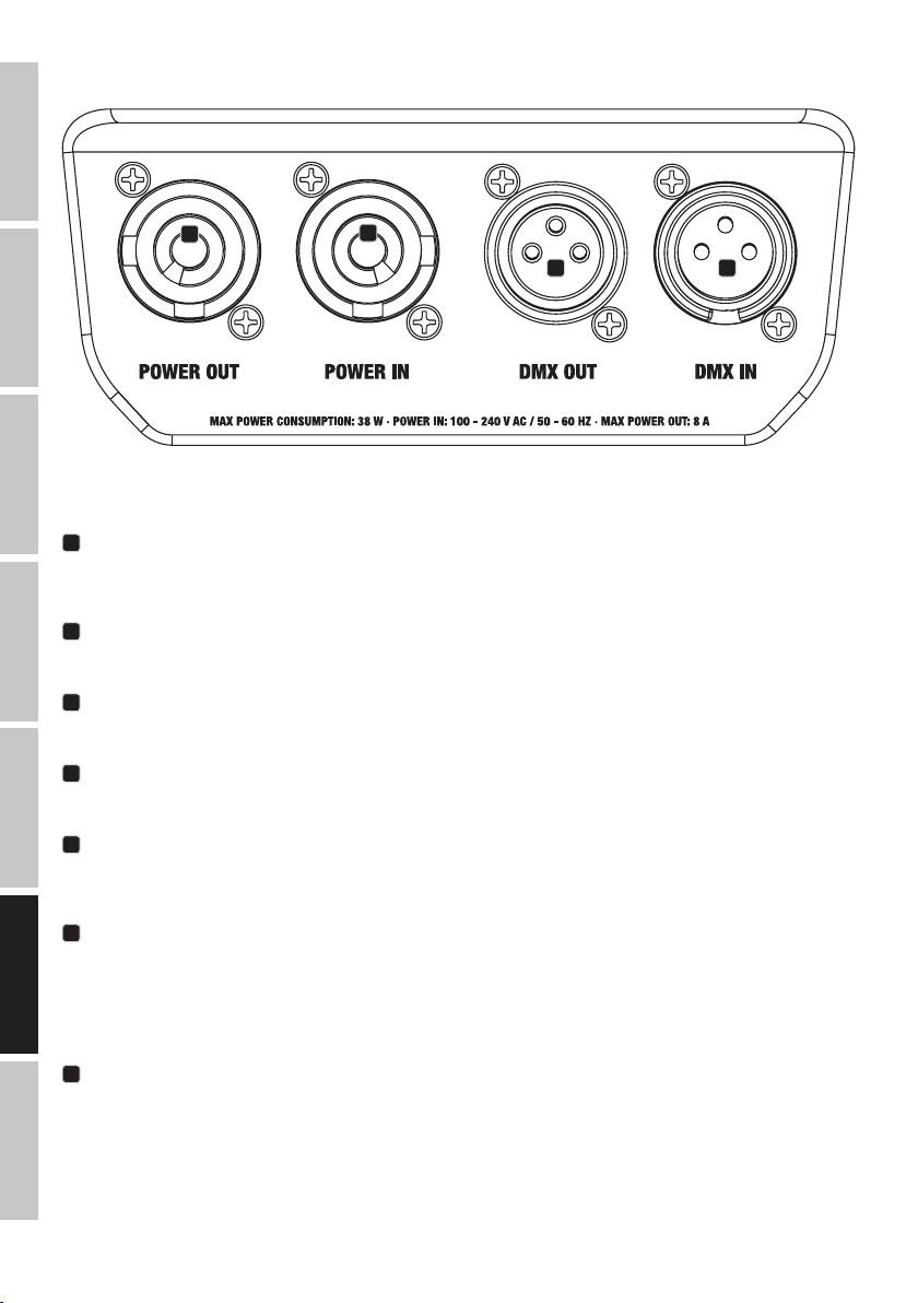
CONNETTORI, ELEMENTI DI COMANDO E DI VISUALIZZAZIONE
ENGLISH
2
DEUTSCH
1
4 3
FRANCAIS
I modelli CLROOTPAR4 e CLROOTPAR6 dispongono di connessioni, elementi di comando e display identici
1
POWER IN
Presa ingresso di rete Power Twist blu. Tensione di esercizio 100 - 240 V AC / 50 - 60 Hz. Un cavo di alimentazione idoneo con
presa Power Twist in dotazione.
ESPAÑOL
2
POWER OUT
Presa uscita di rete Power Twist bianca per l'alimentazione di ulteriori proiettori Cameo (max. 8 A).
3
DMX IN
Connettore XLR maschio a 3 poli per il collegamento di un dispositivo di controllo DMX (ad es. mixer DMX).
4
POLSKI
DMX OUT
Connettore XLR femmina a 3 poli per il reindirizzamento del segnale di controllo del DMX.
5
FUSE
Portafusibili per microfusibili (5 x 20 mm). NOTA IMPORTANTE: Sostituire il fusibile solo con un altro dello stesso tipo e con gli stessi valori.
Se il fusibile continua a saltare rivolgersi a un centro di assistenza autorizzato.
ITALIANO
6
DISPLAY OLED
Il display OLED mostra la modalità di funzionamento attualmente attivata (schermata principale), le voci di menu nel menu di selezione e
il valore numerico o lo stato di funzionamento in alcune voci di menu. Se, entro circa 2 minuti, non avviene alcuna immissione, il display
passa automaticamente alla schermata principale. Nota sulla schermata principale delle modalità di funzionamento con comando esterno:
non appena il segnale di comando si interrompe, i caratteri sul display iniziano a lampeggiare, quando il segnale si ripristina, smettono di
lampeggiare. Partendo dalla schermata principale, la schermata del display può essere ruotata di 180° premendo brevemente il tasto UP.
7
TASTI DI COMANDO
MODE - Premendo MODE si accede al menu di selezione. Premendo ripetutamente questo tasto, viene visualizzata nuovamente la schermata principale. Premendo il MODE senza confermare con ENTER la modifica di un valore o dello stato, verrà ripristinato il valore o lo stato
DMX
confermato in precedenza.
ENTER - Premendo ENTER si accede al livello di menu in cui è possibile apportare le modifiche dei valori e accedere ai sottomenu. Per
confermare le modifiche dei valori e degli stati, premere ENTER.
UP e DOWN - Per la selezione delle singole voci di menu nel menu di selezione (indirizzo DMX, modalità di funzionamento ecc.) e nei
sottomenu. Consentono di modificare a piacere il valore di una voce di menu, come, ad esempio, l'indirizzo DMX.
100
 Loading...