

Cameo CLFLOWERHP User Manual

4 IN 1 32W MOONFLOWER
CLFLOWERHP
USER´S MANUAL
BEDIENUNGSANLEITUNG
MANUEL D´UTILISATION
MANUAL DE USUARIO
INSTRUKCJA OBSŁUGI
MANUALE D‘USO

Introduction
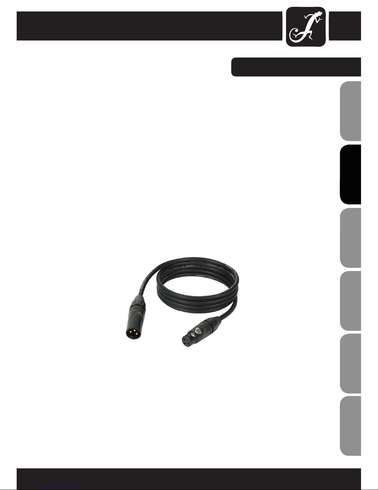
The CLFLOWERHP form Cameo Light is an LED Derby effect with a 32 W RGBW LED. It can be controlled via 5/2
DMX channels, automatically or by music and used as master or slave.
The CLFLOWERHP features an easy to read display with function buttons and LEDs for displaying and setting the
operating modes, 3-pin DMX input and output sockets, as well as IEC power input and output. The comfortable
adjustable bracket and a locking ring allow for reliable assembly of the projector.
2
ENGLISHDEUTSCHFRANCAIS
FRANCAISFRANCAIS FRANCAISFRANCAIS
ESPAÑOLPOLSKIITALIANO
Thank you for choosing this Cameo Light product!
We have designed this product to operate reliably over many years.
Please read this User‘s Manual carefully, so that you can quickly enjoy all the benefits of your DMX device from
Cameo Light.
Learn more about Cameo Light on our website WWW.CAMEOLIGHT.COM.

4 IN 1 32W MOONFLOWER
CLFLOWERHP
3
ITALIANOPOLSKIESPAÑOL
FRANCAISFRANCAIS FRANCAISFRANCAIS
FRANCAISDEUTSCHENGLISH
4
ENGLISHDEUTSCHFRANCAIS
FRANCAISFRANCAIS FRANCAISFRANCAIS
ESPAÑOLPOLSKIITALIANO
PREVENTIVE MEASURES:
1. Please read these instructions carefully.
2. Keep all information and instructions in a safe place.
3. Follow the instructions.
4. Observe all safety warnings. Never remove safety warnings or other information from the equipment.
5. Use the equipment only in the intended manner and for the intended purpose.
6. Use only sufficiently stable and compatible stands and/or mounts (for fixed installations). Make certain that wall
mounts are properly installed and secured. Make certain that the equipment is installed securely and cannot fall down.
7. During installation, observ e the applicable safety regulations for your country.
8. Never install and operate the equipment near radiators, heat registers, ovens or other sources of heat. Make
certain that the equipment is always installed so that is cooled sufficiently and cannot overheat.
9. Never place sources of ignition, e.g., burning candles, on the equipment.
10. Ventilation slits must not be blocked.
11. Do not use this equipment in the immediate vicinity of water (does not apply to special outdoor equipment in this case, observe the special instructions noted below. Do not expose this equipment to flammable materials,
fluids or gases.
12. Make certain that dripping or splashed water cannot enter the equipment. Do not place containers filled with
liquids, such as vases or drinking vessels, on the equipment.
13. Make certain that objects cannot fall into the device.
14. Use this equipment only with the accessories recommended and intended by the manufacturer.
15. Do not open or modify this equipment.
16. After connecting the equipment, check all cables in order to prevent damage or accidents, e.g., due to
tripping hazards.
17. During transport, make certain that the equipment cannot fall down and possibly cause property damage and
personal injuries.
18. If your equipment is no longer functioning properly, if fluids or objects have gotten inside the equipment or
if it has been damaged in anot her way, switch it off immediately and unplug it from the mains outlet (if it is a
powered device). This equipment may only be repaired by authorized, qualified personnel.
19. Clean the equipment using a dry cloth.
20. Comply with all applicable disposal laws in your country. During disposal of packaging, please separate
plastic and paper/cardboard.
21. Plastic bags must be kept out of reach of children.
FOR EQUIPMENT THAT CONNECTS TO THE POWER MAINS:
22. CAUTION: If the power cord of the device is equipped with an earthing contact, then it must be connected to
an outlet with a protective ground. Never deactivate the protective ground of a power cord.
23. If the equipment has been exposed to strong fluctuations in temperature (for example, after transport), do
not switch it on immediately. Moisture and condensation could damage the equipment. Do not switch on the
equipment until it has reached room temperature.
24. Before connecting the equipment to the power outlet, first verify that the mains voltage and frequency match
the values specified on the equipment. If the equipment has a voltage selection switch, connect the equipment to
the power outlet only if the equipment values and the mains power values match. If the included power cord or
power adapter does not fit in your wall outlet, contact your electrician.
25. Do not step on the power cord. Make certain that the power cable does not become kinked, especially at the
mains outlet and/or power adapter and the equipment connector.
26. When connecting the equipment, make certain that the power cord or power adapter is always freely
accessible. Always disconnect the equipment from the power supply if the equipment is not in use or if you want

5
ITALIANOPOLSKIESPAÑOL
FRANCAISFRANCAIS FRANCAISFRANCAIS
FRANCAISDEUTSCHENGLISH
SAFETY:
to clean the equipment. Always unplug the power cord and power adapter from the power outlet at the plug or
adapter and not by pulling on the cord. Never touch the power cord and power adapter with wet hands.
27. Whenever possible, avoid switching the equipment on and off in quick succession because otherwise this
can shorten the useful life of the equipment.
28. IMPORTANT INFORMATION: Replace fuses only with fuses of the same type and rating. If a fuse blows repeatedly, please contact an authorised service centre.
29. To disconnect the equipment from the power mains completely, unplug the power cord or power adapter
from the power outlet.
30. If your device is equipped with a Volex power connector, the mating Volex equipment connector must be
unlocked before it can be removed. However, this also means that the equipment can slide and fall down if
the power cable is pulled, which can lead to personal injuries and/or other damage. For this reason, always be
careful when laying cables.
31. Unplug the power cord and power adapter from the power outlet if there is a risk of a lightning strike or
before extended periods of disuse.
CAUTION
RISK OF ELECTRIC SHOCK
DO NOT OPEN
CAUTION:
Never remove the cover, because otherwise there may be a risk of electric shock. There are no user serviceable
parts inside. Have repairs carried out only by qualified service personnel.
The lightning flash with arrowhead symbol within an equilateral triangle is intended to alert the user
to the presence of uninsulated “dangerous voltage” within the product’s enclosure that may be of
sufficient magnitude to constitute a risk of electrical shock.
The exclamation mark within an equilateral triangle is intended to alert the user to the presence of
important operating and maintenance instructions.
CAUTION! IMPORTANT INFORMATION ABOUT LIGHTING PRODUCTS
1. Do not look into the beam from a distance of less than 40 cm.
2. Do not stare into the beam for extended periods at short-to-medium distances.
3. Do not view the beam directly with optical instruments such as magnifiers.
4. Under some circumstances, stroboscopic effects may trigger epileptic seizures in sensitive individuals!
For this reason, persons who suffer from epilepsy should always avoid places where strobe lights are used.
The product has been developed for professional use in the field of event technology and is not suitable as
household lighting.
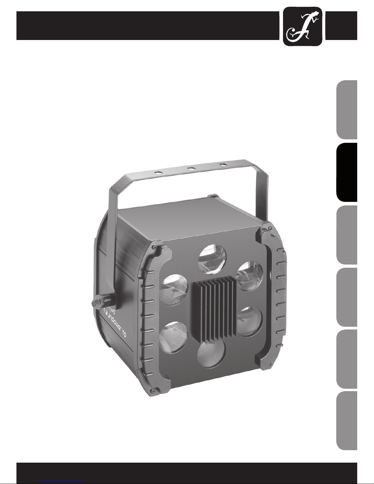
INTRODUCTION:
LED EFFECT PROJECTOR
CLFLOWERHP
CONTROL FUNCTIONS:
• 5-channel DMX control
• 2-channel DMX control
FEATURES:
• DMX-512 control
• Master / Slave operation
• Operating voltage 100 V - 240 V AC
• Power consumption 40 W
• Standalone programs
• Music control via built-in microphone
• Adjustable mounting bracket included
Derby Effect
• A 32 W 4 in 1 RGBW LED
• Rotating reflection mirrors
• 6-way lens system
• 65° beam angle
OPERATION:
The Cameo CLFLOWERHP is a DMX-512 controllable effect projector. The Cameo effect projector can be used
both individually and in master/slave mode, with music control, and via DMX-512 protocol.
6
ENGLISHDEUTSCHFRANCAIS
FRANCAISFRANCAIS FRANCAISFRANCAIS
ESPAÑOLPOLSKIITALIANO
6

CONNECTIONS, CONTROLS AND INDICATORS:
REAR PANEL
7
ITALIANOPOLSKIESPAÑOL
FRANCAISFRANCAIS FRANCAISFRANCAIS
FRANCAISDEUTSCHENGLISH
7
F 1A L / 250V
1
2
3
4
5
6
CONNECTIONS, CONTROLS AND INDICATORS:
LED DISPLAY
The four digit LED display indicates the operating mode and other system information.
CONTROL BUTTONS
MODE: Selecting the different operating modes.
ENTER: Confirming program selection and value changes.
UP and DOWN: Selecting a program, changing the program speed and DMX address.
DMX IN
3-pin male XLR socket for connection of a DMX controller (e.g., DMX mixer).
DMX OUT
3-pin XLR socket for looping through the DMX control signal.
POWER IN
IEC power socket with built-in fuse holder. Connection via the included IEC power cord.
IMPORTANT INFORMATION: Replace the fuse only with a fuse of the same type and rating. If the fuse blows
repeatedly, please contact an authorised service centre.
POWER OUT
IEC mains output socket. Used to supply power to additional CAMEO projectors. Make sure that the total current consumption in amperes (A) of all connected devices does not exceed the specified value on the device.
1
2
3
4
5
6
8
ENGLISHDEUTSCHFRANCAIS
FRANCAISFRANCAIS FRANCAISFRANCAIS
ESPAÑOLPOLSKIITALIANO

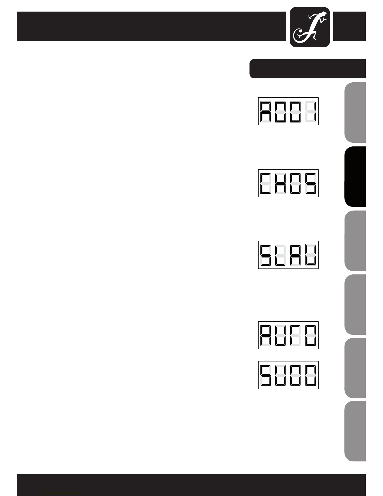
DMX CONTROL AND ADJUSTMENT OF DMX START ADDRESS
Press the MODE button repeatedly until the LED indicator lights up and
displays the DMX start address on the display (A001 - A512). The DMX start
address can be adjusted as desired by using the UP and DOWN buttons. The
synchronous control of several projectors of the same model through a DMX
controller (eg DMX console) can be achieved by adjusting the projectors on
an identical DMX-starting address and connecting them using DMX cables.
CONVERSION OF THE DMX MODE
The projector has a 2-channel and 5-channel mode. If you want to switch
between these two modes, press the MODE button repeatedly until they
reach the address selection (A001-A512). To enter the submenu, select the
DMX mode and press the ENTER button. Depending on the operating mode,
either "CH02" (2-channel mode) or "CH05" (5-channel mode) will appear on
the display. Use the UP and DOWN buttons to select the desired DMX mode.
SLAVE
Press the MODE button repeatedly until the LED indicator lights up and
displays "SLAV" on the display. Once the slave unit has been connected to
the master unit (same model) with the help of a DMX cable (Master = DMX
OUT, Slave = DMX IN), and the master unit has been set to one of the standalone modes (automatic control or music control), the slave unit follows the
master unit. There is no need for selecting a special setting on the master
unit, since the device operates automatically as the Master for both Auto and
Music Control modes.
AUTOMATIC CONTROL
Press the MODE button repeatedly until the LED indicator lights up and
displays "AUTO" on the display. To change the speed of the automatic mode,
press the ENTER button.
MUSIC CONTROL
Press the MODE button repeatedly until the LED indicator lights up and
displays "SUxx" on the display. Using the UP and DOWN buttons, adjust the
sensitivity (SU00 - SU99).
OPERATION:
9
ITALIANOPOLSKIESPAÑOL
FRANCAISFRANCAIS FRANCAISFRANCAIS
FRANCAISDEUTSCHENGLISH
DMX CONTROL:
5-CH-MODE
CHANNEL VALUE FUNCTION
CH1
000 - 015 Red
016 - 031 Green
032 - 047 Blue
048 - 063 White
064 - 079 Red/ Green
080 - 095 Red/ Blue
096 - 111 Red/ White
Colour selection 112 - 127 Green/ Blue
128 - 143 Green/ White
144 - 159 Blue/ White
160 - 175 Red/ Green/ Blue
176 - 191 Red/ Green/ White
192 - 207 Red/ Blue/ White
208 - 223 Green/ Blue/ White
224 - 239 Red/ Green/ Blue/ White
automatic colour change 240 - 255 automatic colour change
CH2
000 - 009 No movement
010 - 120 clockwise slow to fast
mirror rotation 121 - 134 No movement
135 - 245 clockwise slow to fast
246 - 255 No movement
CH3 Stroboscope
000 - 001 No strobe
002 - 255 slow to fast
CH4 Dimmer 000 - 255 0% to 100%
CH5
Colour change speed
000 - 255 slow to fast
2-CH-MODE
CHANNEL VALUE FUNCTION
CH1 Mode Selection
000 - 127 Music Control
128 - 255 Auto Mode
CH2 Mode Options 000 - 255 Sensitivity/ Speed
10
ENGLISHDEUTSCHFRANCAIS
FRANCAISFRANCAIS FRANCAISFRANCAIS
ESPAÑOLPOLSKIITALIANO
11
ITALIANOPOLSKIESPAÑOL
FRANCAISFRANCAIS FRANCAISFRANCAIS
FRANCAISDEUTSCHENGLISH
DMX CONNECTION:
DMX-512
DMX (Digital Multiplex) is the name of a universal transmission protocol for communication between
corresponding devices and controllers. A DMX controller sends DMX data to the connected DMX device(s).
The DMX data is always transmitted as a serial data stream that is forwarded from one connected device to
the next via the "DMX IN" and "DMX OUT" connectors (XLR plug-type connectors) that are found on every
DMX-capable device. (Most controllers only have a DMX output.)
DMX CONNECTION:
DMX is the common "language" via which a very wide range of types and models of equipment from
various manufacturers can be connected with one another and controlled via a central controller, provided
that all of the devices and the controller are DMX-compatible. For optimum data transmission, it is
necessary to keep the connecting cables between the individual devices as short as possible. The order in
which the devices are integrated in the DMX network has no influence on addressing. Thus the device with
the DMX address 1 can be located at any position in the (serial) DMX chain: at the beginning, at the end
or somewhere in the middle. If the DMX address 1 is assigned to a device, the controller "knows" that it
should send all data allocated to address 1 to this device regardless of its position in the DMX network.
The Adam Hall 3 STAR, 4 STAR, and 5 STAR product ranges include an extensive selection of suitable
cables.
SERIAL CONNECTION OF MULTIPLE LIGHTS
1.) Connect the male 3-pole XLR connector of the DMX cable to the DMX output (female 3-pole socket) of
the first light or other DMX device.
2.) Connect the female 3-pole connector of the DMX cable connected to the first light to the DMX input
(male 3-pole socket) of the next DMX device. In like manner, connect the DMX output of this device to the
DMX input of the next device and repeat until all devices have been connected.
Please note that as a rule, DMX devices are connected in series and connections cannot be shared without
active splitters.
12
ENGLISHDEUTSCHFRANCAIS
FRANCAISFRANCAIS FRANCAISFRANCAIS
ESPAÑOLPOLSKIITALIANO
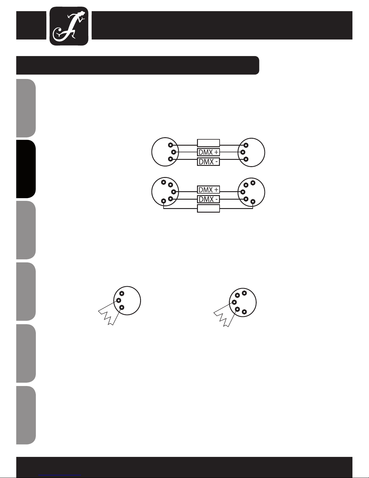
CABLES, TERMINATORS, ADAPTERS:
DMX CABLES:
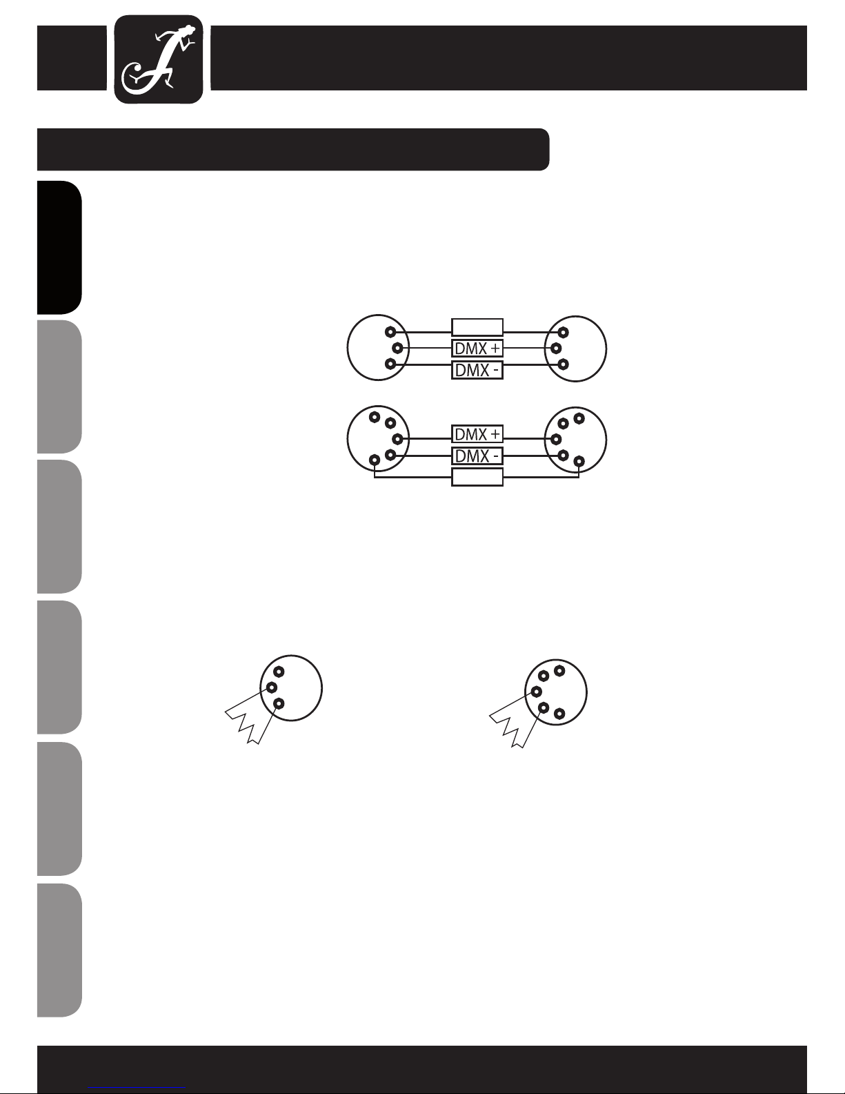
When fabricating your own cables, always observe the illustrations on this page. Never connect the shielding
of the cable to the ground contact of the plug, and always make certain that the shielding does not come into
contact with the housing of the XLR plug. If the shielding is connected to the ground, this can lead to shortcircuiting and system malfunctions.
Pin Assignment:
DMX cable with 3-pin XLR connectors:
DMX cable with 5-pin XLR connectors:
DMX TERMINATORS (TERMINATING RESISTORS):
To prevent system errors, the last device in a DMX chain needs to be equipped with a terminating resistor
(120 ohm, 1/4 Watt).
3-pin XLR connector with a terminating resistor: K3DMXT3
5-pin XLR connector with a terminating resistor: K3DMXT5
Pin Assignment:
3-pin XLR connector: 5-pin XLR connector:
Pins 4 and 5 are
not used.
Shield
2
3
1
2
3
1
1
2
3
4
5
1
2
3
4
5
Shield
2
3
1
1
2
3
4
5
13
ITALIANOPOLSKIESPAÑOL
FRANCAISFRANCAIS FRANCAISFRANCAIS
FRANCAISDEUTSCHENGLISH
CABLES, TERMINATORS, ADAPTERS:
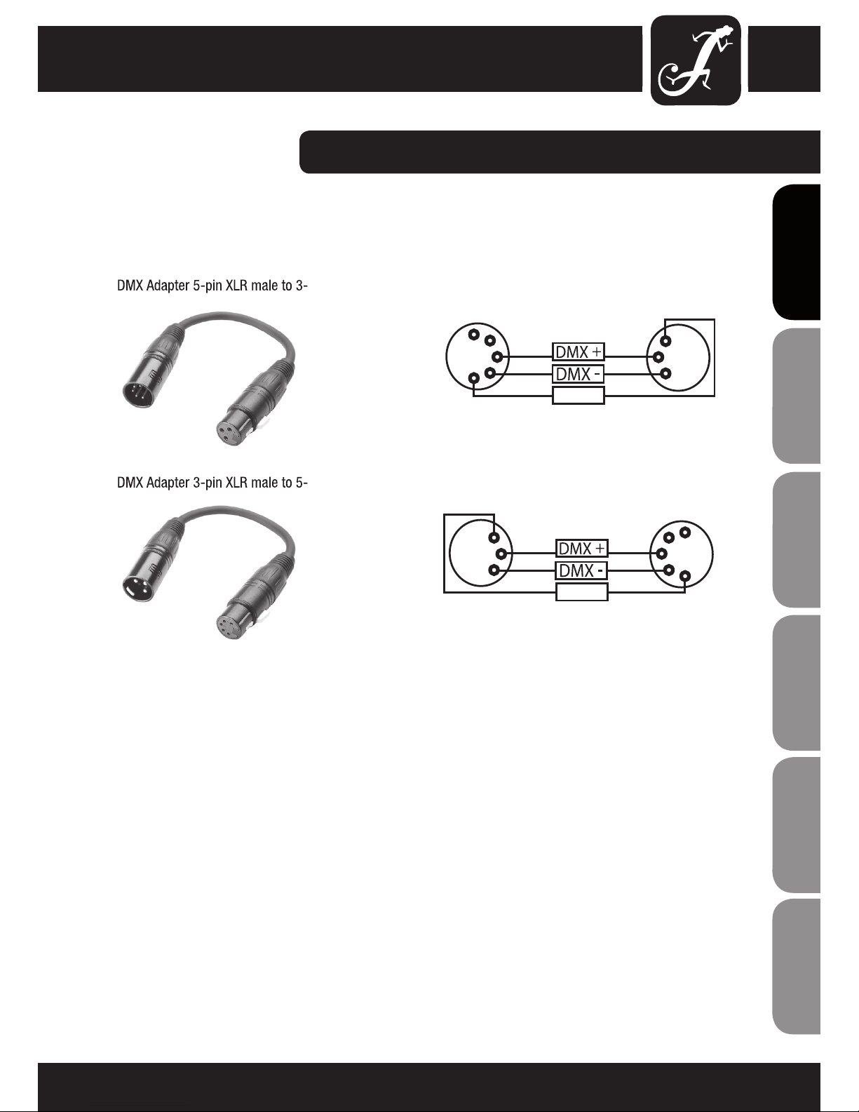
Pins 4 and 5 are not used.
Pins 4 and 5 are not used.
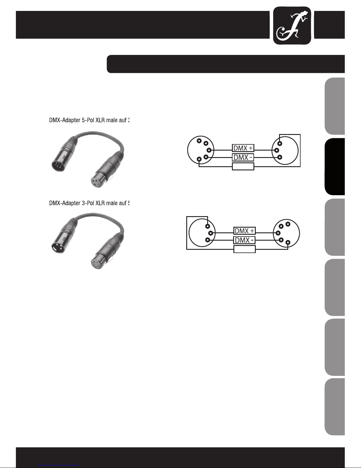
DMX-ADAPTERS:
The combination of DMX devices with 3-pin connectors and DMX devices with 5-pin connectors in a DMX chain
is possible with suitable adapters.
DMX Adapter 5-pin XLR male to 3-pin XLR female: K3DGF0020
Pin Assignment:
DMX Adapter 3-pin XLR male to 5-pin XLR female: K3DHM0020
Pin Assignment:
1
2
3
4
5
Shield
2
3
1
2
3
1
1
2
3
4
5
Shield

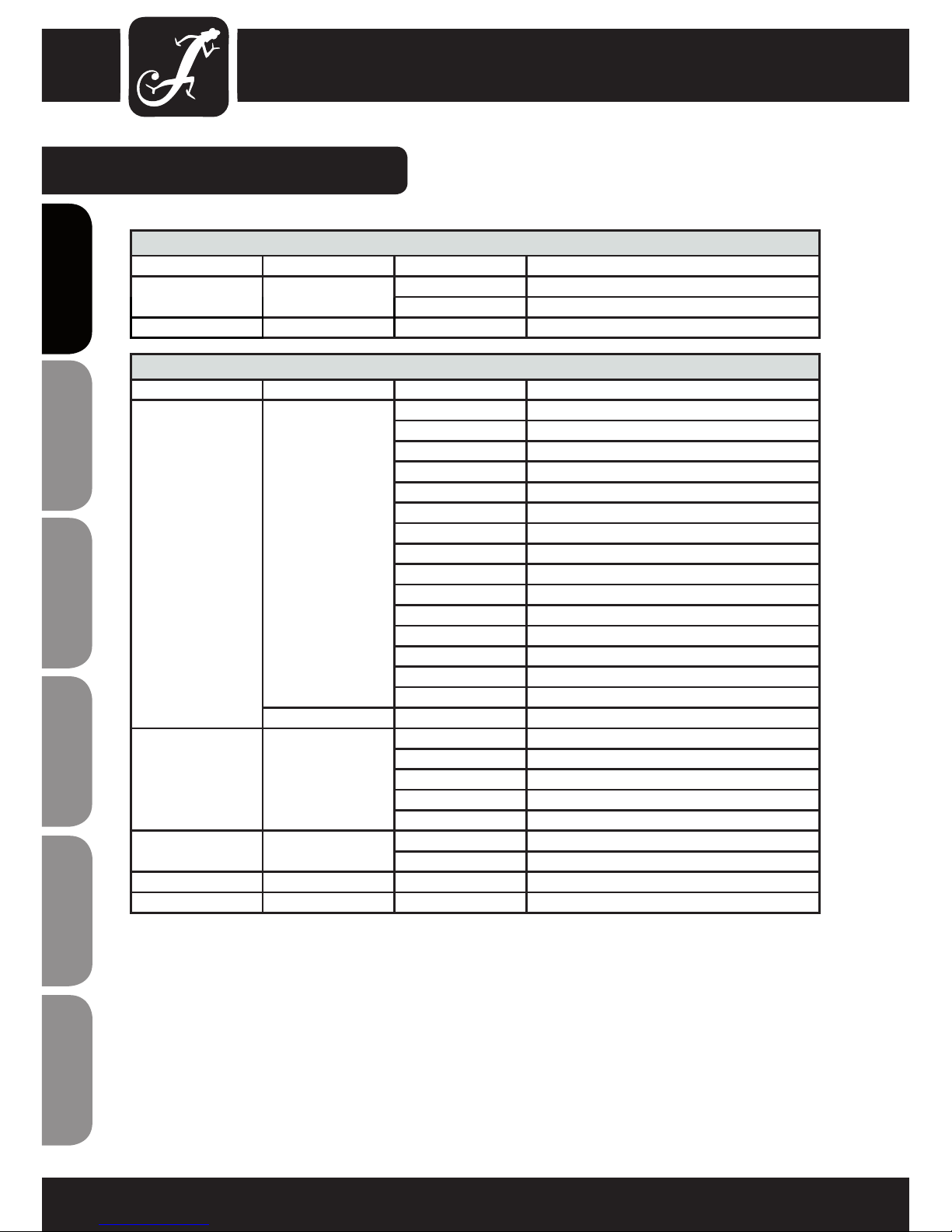
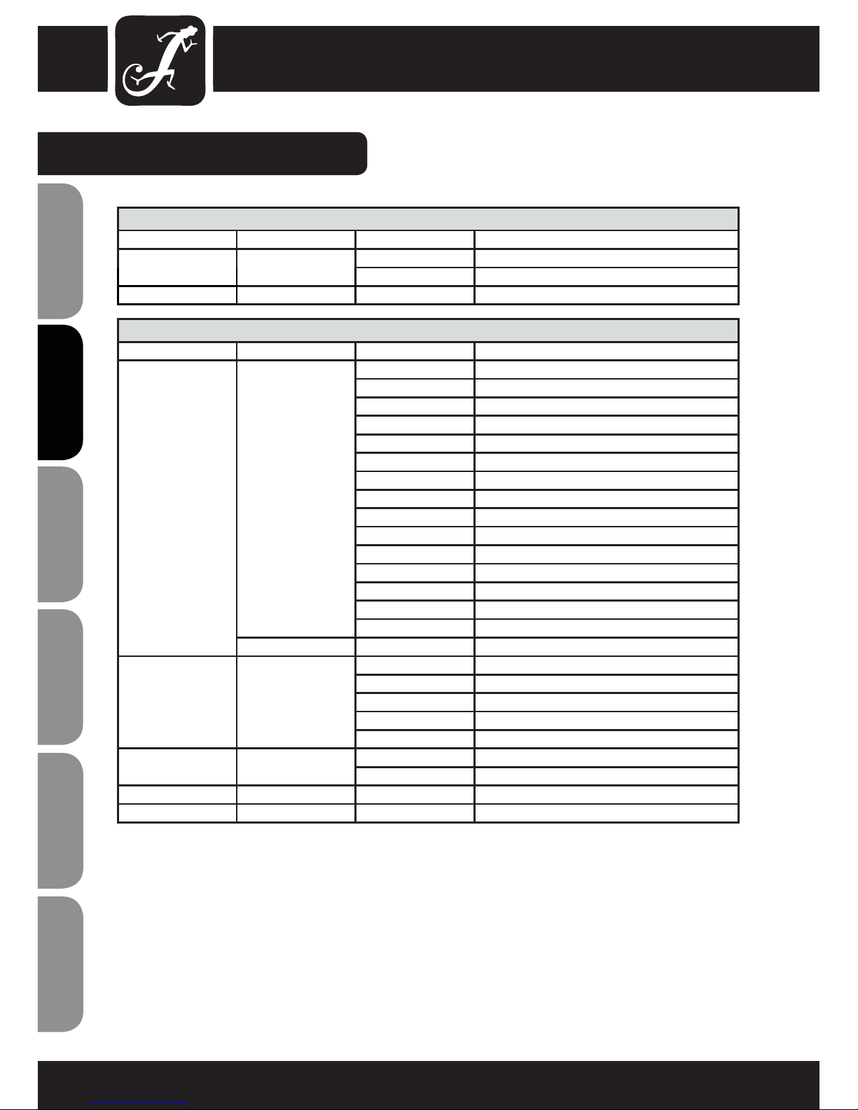
SPECIFICATIONS:
Model Name: CLFLOWERHP
Product Type: LED Derby effect
Type: effect projector
Colour Spectrum RGBW
Number of LEDs 1
LED Type: 4 in 1 32 W RGBW LED
Beam Angle: 65°
DMX Input 3-pin XLR male
DMX Output 3-pin XLR female
DMX Mode: 5-channel, 2-channel
DMX Functions: Auto program, Music Control,
Rotation Speed, Colour,
Dimmer, Strobe
Standalone Functions: Auto program, Music Control,
Controls MODE, ENTER, UP, DOWN buttons
Indicators 4-digit LED display
Power Connector: IEC power input and output
Operating Voltage 100 V-240 V AV / 50-60 Hz
Power Consumption 40 W
Fuse F 1A L / 250 V
Operating Temperature: 45 °C
Relative Humidity: 85%
Housing Material: metal
Housing Colour: black
Dimensions (W x H x D, excluding
bracket):
250
mm x 240 mm x 177 mm
Weight 3 kg
Other Features: adjustable mounting bracket included
14
ENGLISHDEUTSCHFRANCAIS
FRANCAISFRANCAIS FRANCAISFRANCAIS
ESPAÑOLPOLSKIITALIANO

15
ITALIANOPOLSKIESPAÑOL
FRANCAISFRANCAIS FRANCAISFRANCAIS
FRANCAISDEUTSCHENGLISH
MANUFACTURER´S DECLARATIONS:
MANUFACTURER‘S WARRANTY
This warranty extends to the CAMEO branded product you purchased from Adam Hall. The statutory warranty rights
against the vendor shall not be affected by this warranty. Rather, this warranty gives you additional independent
claims against Adam Hall.
With this warranty, Adam Hall ensures that products you have purchased from Adam Hall or Adam Hall partners,
under normal use, are free of defects in material or workmanship for a period of 2 years from the date of purchase.
The warranty period begins on the date of purchase. In order to assert a claim for warranty service, the proof of
date of purchase is provided by the receipt bearing the date of purchase or the date of purchase on the delivery
note. You are entitled to warranty service under the conditions and provisions set out in this document, if a repair
within the warranty period is required.
This warranty applies only to the original purchaser of the products supplied by Adam Hall and is not transferable
to any person to whom the property is transferred by the original purchaser.
Within the warranty period, the defective parts or the product from Adam Hall will be repaired or replaced. Under
the terms of this warranty, all the replaced or removed components become the property of Adam Hall.
In the unlikely event that a product acquired from Adam Hall, repeatedly exhibits a defect, Adam Hall may decide,
at its discretion, to replace this product with a comparable product of at least the same performance.
Adam Hall does not guarantee that the operation of this product will be uninterrupted or error-free. Adam Hall
accepts no responsibility for any damage due to incorrect compliance with the instructions received in the delivery.
This warranty does not extend to:
- wearing parts (eg battery, tubes).
- devices that have had their serial number removed or damaged, or failed as a result of an accident
- inappropriate or abusive use or other external causes
- devices that were not used in accordance with the operating parameters defined in the user documentation
shipped with the product
- devices that have been repaired using parts not made or distributed by Adam Hall
- devices that have been serviced, modified or repaired by someone other than Adam Hall or an authorised service partner.
These terms and conditions constitute the complete and exclusive warranty agreement between you and Adam
Hall regarding the Adam Hall branded product you have purchased.
This warranty is valid only within Europe. Outside of Europe please contact our official distributors.
16
ENGLISHDEUTSCHFRANCAIS
FRANCAISFRANCAIS FRANCAISFRANCAIS
ESPAÑOLPOLSKIITALIANO
MANUFACTURER´S DECLARATIONS:
LIMITATION OF LIABILITY
If your Adam Hall branded hardware product fails to work as warranted above, your sole and exclusive remedy
shall be repair or replacement. Adam Halls’ maximum liability under this limited warranty is expressly limited to
the lesser of the price you have paid for the product or the cost of repair or replacement of any components that
malfunction under conditions of normal use.
Adam Hall is not liable for any damages caused by the product or the failure of the product, including any lost
profits or savings or special, incidental, or consequential damages. Adam Hall is not liable for any claim made by
a third party or made by you for a third party.
This limitation of liability applies whether damages are sought, or claims are made, under this Limited Warranty
or as a tort claim (including negligence and strict product liability), a contract claim, or any other claim, and
cannot be rescinded or changed by anyone. This limitation of liability will be effective even if you have advised
Adam Hall or an authorized representative of Adam Hall of the possibility of any such damages, but not, however,
in the event of claims for damages in connection with personal injuries.
This manufacturer‘s warranty grants you specific rights; depending on jurisdiction (nation or state), you may be
be entitled to additional claims. You are advised to consult applicable state or national laws for a full determination of your rights.
REQUESTING WARRANTY SERVICE
To request warranty service for the product, contact Adam Hall or the Adam Hall authorized reseller from which
you purchased the product.
EC DECLARATION OF CONFORMITY
The equipment marketed by Adam Hall complies (where applicable) with the essential requirements and other
relevant specifications of Directives 1999/5/EC (R&TTE), 2004/108/EC (EMC) und 2006/95/EC (LVD). Additional
information can be found at www.adamhall.com.

17
ITALIANOPOLSKIESPAÑOL
FRANCAISFRANCAIS FRANCAISFRANCAIS
FRANCAISDEUTSCHENGLISH
MANUFACTURER´S DECLARATIONS:
PROPER DISPOSAL OF THIS PRODUCT
(Valid in the European Union and other European countries with waste separation)
This symbol on the product, or the documents accompanying the product, indicates that this appliance may not
be treated as household waste. This is to avoid environmental damage or personal injury due to uncontrolled
waste disposal. Please dispose of this product separately from other waste and have it recycled to promote
sustainable economic activity.
Household users should contact either the retailer where they purchased this product, or their local government
office, for details on where and how they can recycle this item in an environmentally friendly manner.
Business users should contact their supplier and check the terms and conditions of the purchase contract. This
product should not be mixed with other commercial wastes for disposal .
ENVIRONMENTAL PROTECTION AND ENERGY CONSERVATION
Energy conservation is an active contribution to environmental protection. Please turn off all unneeded electrical
devices. To prevent unneeded devices from consuming power in standby mode, disconnect the mains plug.
Adam Hall GmbH, all rights reserved. The technical data and the functional product characteristics can be subject
to modifications. The photocopying, the translation, and all other forms of copying of fragments or of the integrlity
of this user’s manual is prohibited.
Einleitung
Der CLFLOWERHP von Cameo Light ist ein Derby LED-Effekt mit einer 32W RGBW LED. Er kann über 5/2 DMXKanäle, automatisch oder Musik gesteuert und als Master oder Slave eingesetzt werden.
Der CLFLOWERHP verfügt über ein leicht lesbares Display mit Funktionstasten und LEDs zur Anzeige und
Einstellung der Betriebsmodi, 3-Pol DMX Eingangs- und Ausgangsbuchsen, sowie IEC-Netzein- und Ausgang. Der
bequem verstellbare Bügel und ein Sicherungsring ermöglichen die zuverlässige Montage des Scheinwerfers.
ENGLISHDEUTSCHFRANCAIS
FRANCAISFRANCAIS FRANCAISFRANCAIS
ESPAÑOLPOLSKIITALIANO
18
Wir freuen uns, dass Sie sich für ein Produkt von Cameo Light entschieden haben!
Dieses Gerät wurde unter hohen Qualitätsanforderungen entwickelt und gefertigt, um viele Jahre einen
reibungslosen Betrieb zu gewährleisten.
Bitte lesen Sie diese Bedienungsanleitung sorgfältig, damit Sie Ihr neues DMX-Gerät von Cameo Light schnell
optimal einsetzen können.
Weitere Informationen über Cameo Light erhalten Sie auf unserer Website WWW.CAMEOLIGHT.COM.
4 IN 1 32W MOONFLOWER
CLFLOWERHP
ITALIANOPOLSKIESPAÑOL
FRANCAISFRANCAIS FRANCAISFRANCAIS
FRANCAISDEUTSCHENGLISH
19

ENGLISHDEUTSCHFRANCAIS
FRANCAISFRANCAIS FRANCAISFRANCAIS
ESPAÑOLPOLSKIITALIANO
20
SICHERHEITSHINWEISE:
1. Lesen Sie diese Anleitung bitte sorgfältig durch.
2. Bewahren Sie alle Informationen und Anleitungen an einem sicheren Ort auf.
3. Befolgen Sie die Anweisungen.
4. Beachten Sie alle Warnhinweise. Entfernen Sie keine Sicherheitshinweise oder andere Informationen vom Gerät.
5. Verwenden Sie das Gerät nur in der vorgesehenen Art und Weise.
6. Verwenden Sie ausschließlich stabile und passende Stative bzw. Befestigungen (bei Festinstallationen). Stellen
Sie sicher, dass Wandhalterungen ordnungsgemäß installiert und gesichert sind. Stellen Sie sicher, dass das
Gerät sicher installiert ist und nicht herunterfallen kann.
7. Beachten Sie bei der Installation die für Ihr Land geltenden Sicherheitsvorschriften.
8. Installieren und betreiben Sie das Gerät nicht in der Nähe von Heizkörpern, Wärmespeichern, Öfen oder
sonstigen Wärmequellen. Sorgen Sie dafür, dass das Gerät immer so installiert ist, dass es ausreichend gekühlt
wird und nicht überhitzen kann.
9. Platzieren Sie keine Zündquellen wie z.B. brennende Kerzen auf dem Gerät.
10. Lüftungsschlitze dürfen nicht blockiert werden.
11. Betreiben Sie das Gerät nicht in unmittelbarer Nähe von Wasser (gilt nicht für spezielle Outdoor Geräte beachten Sie in diesem Fall bitte die im Folgenden vermerkten Sonderhinweise). Bringen Sie das Gerät nicht mit
brennbaren Materialien, Flüssigkeiten oder Gasen in Berührung.
12. Sorgen Sie dafür, dass kein Tropf- oder Spritzwasser in das Gerät eindringen kann. Stellen Sie keine mit
Flüssigkeit gefüllten Behältnisse wie Vasen oder Trinkgefäße auf das Gerät.
13. Sorgen Sie dafür, dass keine Gegenstände in das Gerät fallen können.
14. Betreiben Sie das Gerät nur mit dem vom Hersteller empfohlenen und vorgesehenen Zubehör.
15. Öffnen Sie das Gerät nicht und verändern Sie es nicht.
16. Überprüfen Sie nach dem Anschluss des Geräts alle Kabelwege, um Schäden oder Unfälle, z. B. durch
Stolperfallen zu vermeiden.
17. Achten Sie beim Transport darauf, dass das Gerät nicht herunterfallen und dabei möglicherweise Sach- und
Personenschäden verursachen kann.
18. Wenn Ihr Gerät nicht mehr ordnungsgemäß funktioniert, Flüssigkeiten oder Gegenstände in das Geräteinnere
gelangt sind, oder das Gerät anderweitig beschädigt wurde, schalten Sie es sofort aus und trennen es von der
Netzsteckdose (sofern es sich um ein aktives Gerät handelt). Dieses Gerät darf nur von autorisiertem Fachpersonal repariert werden.
19. Verwenden Sie zur Reinigung des Geräts ein trockenes Tuch.
20. Beachten Sie alle in Ihrem Land geltenden Entsorgungsgesetze. Trennen Sie bei der Entsorgung der Verpackung bitte Kunststoff und Papier bzw. Kartonagen voneinander.
21. Kunststoffbeutel müssen außer Reichweite von Kindern aufbewahrt werden.
BEI GERÄTEN MIT NETZANSCHLUSS:
22. ACHTUNG: Wenn das Netzkabel des Geräts mit einem Schutzkontakt ausgestattet ist, muss es an einer
Steckdose mit Schutzleiter angeschlossen werden. Deaktivieren Sie niemals den Schutzleiter eines Netzkabels.
23. Schalten Sie das Gerät nicht sofort ein, wenn es starken Temperaturschwankungen ausgesetzt war (beispielsweise nach dem Transport). Feuchtigkeit und Kondensat könnten das Gerät beschädigen. Schalten Sie das
Gerät erst ein, wenn es Zimmertemperatur erreicht hat.
24. Bevor Sie das Gerät an die Steckdose anschließen, prüfen Sie zuerst, ob die Spannung und die Frequenz
des Stromnetzes mit den auf dem Gerät angegebenen Werten übereinstimmen. Verfügt das Gerät über einen
Spannungswahlschalter, schließen Sie das Gerät nur an die Steckdose an, wenn die Gerätewerte mit den Werten
des Stromnetzes übereinstimmen. Wenn das mitgelieferte Netzkabel bzw. der mitgelieferte Netzadapter nicht in
Ihre Netzsteckdose passt, wenden Sie sich an Ihren Elektriker.

ITALIANOPOLSKIESPAÑOL
FRANCAISFRANCAIS FRANCAISFRANCAIS
FRANCAISDEUTSCHENGLISH
21
SICHERHEITSHINWEISE:
25. Treten Sie nicht auf das Netzkabel. Sorgen Sie dafür, dass spannungsführende Kabel speziell an der Netzbuchse bzw. am Netzadapter und der Gerätebuchse nicht geknickt werden.
26. Achten Sie bei der Verkabelung des Geräts immer darauf, dass das Netzkabel bzw. der Netzadapter stets frei
zugänglich ist. Trennen Sie das Gerät stets von der Stromzuführung, wenn das Gerät nicht benutzt wird, oder
Sie das Gerät reinigen möchten. Ziehen Sie Netzkabel und Netzadapter immer am Stecker bzw. am Adapter und
nicht am Kabel aus der Steckdose. Berühren Sie Netzkabel und Netzadapter niemals mit nassen Händen.
27. Schalten Sie das Gerät möglichst nicht schnell hintereinander ein und aus, da sonst die Lebensdauer des
Geräts beeinträchtigt werden könnte.
28. WICHTIGER HINWEIS: Ersetzen Sie Sicherungen ausschließlich durch Sicherungen des gleichen Typs und
Wertes. Sollte eine Sicherung wiederholt auslösen, wenden Sie sich bitte an ein autorisiertes Servicezentrum.
29. Um das Gerät vollständig vom Stromnetz zu trennen, entfernen Sie das Netzkabel bzw. den Netzadapter aus
der Steckdose.
30. Wenn Ihr Gerät mit einem Volex-Netzanschluss bestückt ist, muss der passende Volex-Gerätestecker
entsperrt werden, bevor er entfernt werden kann. Das bedeutet aber auch, dass das Gerät durch ein Ziehen am
Netzkabel verrutschen und herunterfallen kann, wodurch Personen verletzt werden und/oder andere Schäden
auftreten können. Verlegen Sie Ihre Kabel daher immer sorgfältig.
31. Entfernen Sie Netzkabel und Netzadapter aus der Steckdose bei Gefahr eines Blitzschlags oder wenn Sie das
Gerät länger nicht verwenden.
CAUTION
RISK OF ELECTRIC SHOCK
DO NOT OPEN
ACHTUNG:
Entfernen Sie niemals die Abdeckung, da sonst das Risiko eines elektrischen Schlages besteht. Im Inneren des
Geräts befinden sich keine Teile, die vom Bediener repariert oder gewartet werden können. Lassen Sie Reparaturen ausschließlich von qualifiziertem Servicepersonal durchführen.
Das gleichschenkelige Dreieck mit Blitzsymbol warnt vor nichtisolierten, gefährlichen Spannungen
im Geräteinneren, die einen elektrischen Schlag verursachen können.
Das gleichschenkelige Dreieck mit Ausrufungszeichen kennzeichnet wichtige Bedienungs- und
Wartungshinweise.
VORSICHT! WICHTIGE HINWEISE IN BEZUG AUF LICHT-PRODUKTE
1. Blicken Sie nicht aus Entfernungen von unter 40 cm in den Lichtstrahl.
2. Blicken Sie niemals längere Zeit aus kurzem bis mittlerem Abstand in den Lichtstrahl.
3. Blicken Sie niemals mit optischen Geräten wie Vergrößerungsgläsern in den Lichtstrahl.
4. Stoboskopeffekte können unter Umständen bei empfindlichen Menschen epileptische Anfälle auslösen! Epilepsiekranke Menschen sollten daher unbedingt Orte meiden, an denen Stroboskope eingesetzt werden.
Das Produkt ist für den professionellen Einsatz im Bereich der Veranstaltungstechnik entwickelt worden und ist
nicht für die Raumbeleuchtung in Haushalten geeignet.

EINFÜHRUNG:
LED EFFEKT SCHEINWERFER
CLFLOWERHP
STEUERUNGSFUNKTIONEN:
• 5-Kanal DMX-Steuerung
• 2-Kanal DMX-Steuerung
EIGENSCHAFTEN:
• DMX-512 Steuerung
• Master / Slave Betrieb
• Betrtiebsspannung 100V - 240V AC
• Leistungsaufnahme 40W
• Standalone Programme
• Musiksteuerung über eingebautes Mikrofon
• Verstellbarer Montagebügel inklusive
Derby-Effekt
• Eine 32W 4 in 1 RGBW LED
• Rotierende Reflexionsspiegel
• 6-fach Linsensystem
• 65° Abstrahlwinkel
BEDIENUNG:
Der Cameo CLFLOWER HP ist ein DMX-512-steuerbarer Effekt-Scheinwerfer. Der Cameo Effekt-Scheinwerfer
lässt sich sowohl als Standalone-Gerät, im Master/Slave-Betrieb, per Musiksteuerung und via DMX-512-Protokoll
betreiben.
ENGLISHDEUTSCHFRANCAIS
FRANCAISFRANCAIS FRANCAISFRANCAIS
ESPAÑOLPOLSKIITALIANO
22

ANSCHLÜSSE, BEDIEN- UND ANZEIGEELEMENTE:
RÜCKSEITE
ITALIANOPOLSKIESPAÑOL
FRANCAISFRANCAIS FRANCAISFRANCAIS
FRANCAISDEUTSCHENGLISH
23
F 1A L / 250V
1
2
3
4
5
6
ANSCHLÜSSE, BEDIEN- UND ANZEIGEELEMENTE:
LED DISPLAY
Das vierstellige LED-Display zeigt die Betriebsart und weitere Systeminformationen an.
BEDIENTASTEN
MODE: Auswählen der verschiedenen Betriebsarten.
ENTER: Bestätigen von Programmauswahl und Wertänderungen.
UP und DOWN: Auswahl eines Programmes, ändern der Programmgeschwindigkeit und DMX-Adresse.
DMX IN
3-polige, männliche XLR-Buchse zum Anschließen eines DMX-Kontrollgeräts (z.B. DMX-Mischpult).
DMX OUT
3-polige weibliche XLR-Buchse zum Weiterleiten des DMX-Steuersignals.
POWER IN
IEC Netzbuchse mit integriertem Sicherungshalter. Anschluss über das mitgelieferte IEC-Netzkabel.
WICHTIGER HINWEIS: Ersetzen Sie die Sicherung ausschließlich durch eine Sicherung des gleichen Typs
und mit gleichen Werten. Sollte die Sicherung wiederholt auslösen, wenden Sie sich bitte an ein autorisiertes
Servicezentrum.
POWER OUT
IEC Netzausgangsbuchse. Dient der Netzversorgung weiterer CAMEO Scheinwerfer. Achten Sie darauf, dass
die gesamte Stromaufnahme aller angeschlossenen Geräte den auf dem Gerät in Ampere (A) angegebenen
Wert nicht überschreitet.
1
2
3
4
5
6
ENGLISHDEUTSCHFRANCAIS
FRANCAISFRANCAIS FRANCAISFRANCAIS
ESPAÑOLPOLSKIITALIANO
24
DMX-STEUERUNG UND EINSTELLEN DER DMX-STARTADRESSE
Drücken Sie die MODE-Taste so oft, bis das LED-Display leuchtet und im Display
die DMX-Startadresse angezeigt wird (A001 - A512). Die DMX-Startadresse
kann mit Hilfe der Tasten UP und DOWN wunschgemäß eingestellt werden.
Die synchrone Ansteuerung mehrerer Scheinwerfer des gleichen Modells
durch ein DMX-Steuergerät (z.B. DMX-Mischpult) erreichen Sie, indem Sie die
Scheinwerfer auf eine identische DMX-Startadresse einstellen und mit Hilfe von
DMX-Kabeln verbinden.
UMSTELLUNG DES DMX-MODUS
Der Scheinwerfer verfügt über einen 2-Kanal und eine 5-Kanal Modus. Wenn Sie
zwischen diesen beiden Modi wechseln möchten, drücken Sie die MODE-Taste
so oft, bis sie zur Adressauswahl kommen (A001-A512). Um in das Untermenü
zur Auswahl des DMX Modus zu kommen drücken Sie die ENTER-Taste. Nun
erscheint je nach aktiviertem Betriebsmodus entweder „CH02“ (2-Kanal Modus)
oder „CH05“ (5-Kanal Modus) auf dem Display. Mit den UP- und DOWN-Tasten
können Sie den gewünschten DMX-Modus auswählen.
SLAVE
Drücken Sie die MODE-Taste so oft, bis das LED-Display leuchtet und im Display
„SLAV“ angezeigt wird. Sobald Sie die Slave- mit der Master-Einheit (gleiches
Modell) mit Hilfe eines DMX-Kabels (Master = DMX OUT, Slave = DMX IN)
verbunden haben und die Master-Einheit auf eine der Standalone Betriebsarten
(automatische Steuerung bzw. Musiksteuerung) eingestellt haben, folgt die
Slave-Einheit der Master-Einheit. An der Master-Einheit müssen keine speziellen
Einstellungen vorgenommen werden, sowohl im Auto- als auch im SoundModus arbeitet das Gerät automatisch als Master.
AUTOMATISCHE STEUERUNG
Drücken Sie die MODE-Taste so oft, bis das LED-Display leuchtet und im Display
„AUTO“ angezeigt wird. Um die Geschwindigkeit des automatischen Moduses zu
verändern drücken Sie die ENTER-Taste.
MUSIKSTEUERUNG
Drücken Sie die MODE-Taste so oft, bis das LED-Display leuchtet und im Display
„SUxx“ angezeigt wird. Mit Hilfe der Tasten UP und DOWN können Sie die
Empfindlichkeit in einstellen (SU00 - SU99).
BEDIENUNG:
ITALIANOPOLSKIESPAÑOL
FRANCAISFRANCAIS FRANCAISFRANCAIS
FRANCAISDEUTSCHENGLISH
25
DMX STEUERUNG:
5-CH-MODE
KANAL WERT FUNKTION
CH1
000 - 015 Rot
016 - 031 Grün
032 - 047 Blau
048 - 063 Weiß
064 - 079 Rot/ Grün
080 - 095 Rot/ Blau
096 - 111 Rot/ Weiß
Farbauswahl 112 - 127 Grün/ Blau
128 - 143 Grün/ Weiß
144 - 159 Blau/ Weiß
160 - 175 Rot/ Grün/ Blau
176 - 191 Rot/ Grün/ Weiß
192 - 207 Rot/ Blau/ Weiß
208 - 223 Grün/ Blau/ Weiß
224 - 239 Rot/ Grün/ Blau/ Weiß
automatische Farbwechsel 240 - 255 automatische Farbwechsel
CH2
000 - 009 keine Bewegung
010 - 120 im Uhrzeigersinn langsam nach schnell
Spiegel Rotation 121 - 134 keine Bewegung
135 - 245 im Uhrzeigersinn langsam nach schnell
246 - 255 keine Bewegung
CH3 Stroboskop
000 - 001 kein Stroboskop
002 - 255 langsam nach schnell
CH4 Dimmer 000 - 255 0 % to 100 %
CH5
Farbwechsel Geschwindigkeit
000 - 255 langsam nach schnell
2-CH-MODE
KANAL WERT FUNKTION
CH1 Modus Auswahl
000 - 127 Musiksteuerung
128 - 255 Auto Modus
CH2 Modus Optionen 000 - 255 Empfindlichkeit/ Geschwindigkeit
ENGLISHDEUTSCHFRANCAIS
FRANCAISFRANCAIS FRANCAISFRANCAIS
ESPAÑOLPOLSKIITALIANO
26
ITALIANOPOLSKIESPAÑOL
FRANCAISFRANCAIS FRANCAISFRANCAIS
FRANCAISDEUTSCHENGLISH
27
DMX-512
DMX (Digital Multiplex) ist die Bezeichnung für ein universelles Übertragungsprotokoll für die
Kommunikation zwischen entsprechenden Geräten und Controllern. Ein DMX-Controller sendet DMXDaten an das/die angeschlossene(n) DMX-Gerät(e). Die DMX-Datenübertragung erfolgt stets als serieller
Datenstrom, der über die an jedem DMX-fähigen Gerät vorhandenen DMX IN- und DMX OUT-Anschlüsse
(XLR-Steckverbinder) von einem angeschlossenen Gerät an das nächste weitergeleitet wird, wobei
die maximale Anzahl der Geräte 32 nicht überschreiten darf. Das letzte Gerät der Kette ist mit einem
Abschlussstecker (Terminator) zu bestücken.
DMX-VERBINDUNG:
DMX ist die gemeinsame "Sprache", über die sich die unterschiedlichsten Gerätetypen und Modelle
verschiedener Hersteller miteinander verkoppeln und über einen zentralen Controller steuern lassen, sofern
sämtliche Geräte und der Controller DMX-kompatibel sind. Für eine optimale Datenübertragung ist es
erforderlich, die Verbindungskabel zwischen den einzelnen Geräten so kurz wie möglich zu halten.
Die Reihenfolge, in der die Geräte in das DMX-Netzwerk eingebunden sind, hat keinen Einfluss auf die
Adressierung. So kann sich das Gerät mit der DMX-Adresse 1 an einer beliebigen Position in der (seriellen)
DMX-Kette befinden, am Anfang, am Ende oder irgendwo in der Mitte. Wird einem Gerät die DMX-Adresse
1 zugewiesen, "weiß" der Controller, dass er alle der Adresse 1 zugeordneten Daten an dieses Gerät
senden soll, ungeachtet seiner Position im DMX-Verbund.
SERIELLE VERKOPPLUNG MEHRERER SCHEINWERFER
1. Verbinden Sie den männlichen XLR-Stecker (3-Pol oder 5-Pol) des DMX-Kabels mit dem DMX-Ausgang
(weibliche XLR-Buchse) des ersten DMX-Geräts (z.B. DMX-Controller).
2. Verbinden Sie den weibliche XLR-Stecker des an den ersten Scheinwerfer angeschlossenen DMX-Kabels
mit dem DMX-Eingang (männliche XLR-Buchse) des nächsten DMX-Geräts. Verbinden Sie den DMXAusgang dieses Geräts in der gleichen Weise mit dem DMX-Eingang des nächsten Geräts und so weiter.
Bitte beachten Sie, dass DMX-Geräte grundsätzlich seriell verschaltet werden und die Verbindungen nicht
ohne aktiven Splitter geteilt werden können. Die maximale Anzahl der DMX-Geräte einer DMX-Kette darf 32
nicht überschreiten.
Eine umfangreiche Auswahl geeigneter DMX-Kabel finden Sie in den Adam Hall Produktlinien 3 STAR, 4 STAR
und 5 STAR.
DMX-TECHNIK:
ENGLISHDEUTSCHFRANCAIS
FRANCAISFRANCAIS FRANCAISFRANCAIS
ESPAÑOLPOLSKIITALIANO
28
KABEL, ABSCHLUSSSTECKER, ADAPTER:
DMX-KABEL:
Beachten Sie bei der Anfertigung eigener Kabel unbedingt die Abbildungen auf dieser Seite. Verbinden Sie auf
keinen Fall die Abschirmung des Kabels mit dem Massekontakt des Steckers, und achten Sie darauf, dass die
Abschirmung nicht mit dem XLR-Steckergehäuse in Kontakt kommt. Hat die Abschirmung Massekontakt, kann
dies zu Systemfehlern führen.
Steckerbelegung:
DMX-Kabel mit 3-Pol XLR-Steckern:
DMX-Kabel mit 5-Pol XLR-Steckern:
DMX-ABSCHLUSSSTECKER (TERMINATOR):
Um Systemfehler zu vermeiden, ist das letzte Gerät einer DMX-Kette mit einem Abschlusswiderstand zu
bestücken (120 Ohm, 1/4 Watt).
3-Pol XLR-Stecker mit Abschlusswiderstand: K3DMXT3
5-Pol XLR-Stecker mit Abschlusswiderstand: K3DMXT5
Steckerbelegung:
3-Pol XLR-Stecker: 5-Pol XLR-Stecker:
Pin 4 und 5 sind
nicht belegt.
Shield
2
3
1
2
3
1
1
2
3
4
5
1
2
3
4
5
Shield
2
3
1
1
2
3
4
5
ITALIANOPOLSKIESPAÑOL
FRANCAISFRANCAIS FRANCAISFRANCAIS
FRANCAISDEUTSCHENGLISH
29
KABEL, ABSCHLUSSSTECKER, ADAPTER:
Pin 4 und 5 sind nicht belegt.
Pin 4 und 5 sind nicht belegt.
DMX-ADAPTER:
Die Kombination von DMX-Geräten mit 3-Pol Anschlüssen und DMX-Geräten mit 5-Pol Anschlüssen in einer
DMX-Kette ist mit Hilfe von Adaptern ebenso möglich.
DMX-Adapter 5-Pol XLR male auf 3-Pol XLR female: K3DGF0020
Steckerbelegung
DMX-Adapter 3-Pol XLR male auf 5-Pol XLR female: K3DHM0020
Steckerbelegung
1
2
3
4
5
Shield
2
3
1
2
3
1
1
2
3
4
5
Shield

TECHNISCHE DATEN:
Modellbezeichnung: CLFLOWERHP
Produktart: LED Derby-Effekt
Typ: Effekt-Strahler
Farbspektrum RGBW
LED-Anzahl 1
LED-Typ 4 in 1 32W RGBW LED
Abstrahlwinkel 65°
DMX-Eingang 3-Pol XLR männlich
DMX-Ausgang 3-Pol XLR weiblich
DMX-Modus 5-Kanal, 2-Kanal
DMX-Funktionen Auto-Programm, Sound-Programm,
Rotationsgeschwindigkeit, Farbe,
Dimmer, Stroboskop
Standalone Funktionen Auto-Programm, Sound-Programm
Bedienelemente MODE-, ENTER-, UP-, DOWN- Tasten
Anzeigeelemente 4-Stelliges LED-Display
Stromversorgungsanschluss IEC Ein- und Ausgang
Betriebsspannung 100 V-240 V AV/ 50-60 Hz
Leistungsaufnahme 40 W
Sicherung F 1A L / 250V
Betriebstemperatur 45 °C
Relative Luftfeuchtigkeit 85%
Gehäusematerial Metall
Gehäusefarbe Schwarz
Abmessungen (B x H x T, ohne Bügel) 250 mm x 240 mm x 177 mm
Gewicht 3 kg
Weitere Eigenschaften verstellbarer Metallbügel inklusive
ENGLISHDEUTSCHFRANCAIS
FRANCAISFRANCAIS FRANCAISFRANCAIS
ESPAÑOLPOLSKIITALIANO
30
 Loading...