

Cameo LED DROPIX 66, CLDROPIX176, LED DROPIX SET, CLDROPIXSET, LED DROPIX 176 User Manual
...
LED DROPIX 66 / 176 / SET
CLDROPIX66
CLDROPIX176
CLDROPIXSET
CLDROPIXEXT5
USER´S MANUAL
BEDIENUNGSANLEITUNG
MANUEL D´UTILISATION
MANUAL DE USUARIO
INSTRUKCJA OBSŁUGI
MANUALE D‘USO

Introduction
The mobile LED curtains LED DROPIX 66 and LED DROPIX 176 from Cameo Light generate 30 impressive matrix
effects with RGB colour mixing and a wide viewing angle.
The particularly bright and durable tri-colour SMD LEDs are arranged at 18 cm intervals on opaque Molton fabric
with eyelets all around for easy suspension and are certified according to DIN4102 B1.
2
ENGLISHDEUTSCHFRANCAIS
FRANCAISFRANCAIS FRANCAISFRANCAIS
ESPAÑOLPOLSKIITALIANO
Thank you for choosing this Cameo Light product!
We have designed this product to operate reliably over many years.
Please read this User‘s Manual carefully, so that you can quickly enjoy all the benefits of your DMX device from
Cameo Light.
Learn more about Cameo Light on our website WWW.CAMEOLIGHT.COM.
LED DROPIX 66 / 176 / SET
CLDROPIX66
CLDROPIX176
CLDROPIXSET
CLDROPIXEXT5
3
ITALIANOPOLSKIESPAÑOL
FRANCAISFRANCAIS FRANCAISFRANCAIS
FRANCAISDEUTSCHENGLISH
4
ENGLISHDEUTSCHFRANCAIS
FRANCAISFRANCAIS FRANCAISFRANCAIS
ESPAÑOLPOLSKIITALIANO
1. Please read these instructions carefully.
2. Keep all information and instructions in a safe place.
3. Follow the instructions.
4. Observe all safety warnings. Never remove safety warnings or other information from the equipment.
5. Use the equipment only in the intended manner and for the intended purpose.
6. Use only sufficiently stable and compatible stands and/or mounts (for fixed installations). Make certain that wall
mounts are properly installed and secured. Make certain that the equipment is installed securely and cannot fall down.
7. During installation, observ e the applicable safety regulations for your country.
8. Never install and operate the equipment near radiators, heat registers, ovens or other sources of heat. Make
certain that the equipment is always installed so that is cooled sufficiently and cannot overheat.
9. Never place sources of ignition, e.g., burning candles, on the equipment.
10. Ventilation slits must not be blocked.
11. This appliance is designed exclusively for indoor use, do not use this equipment in the immediate vicinity of
water (does not apply to special outdoor equipment - in this case, observe the special instructions noted below).
Do not expose this equipment to flammable materials, fluids or gases.
12. Make certain that dripping or splashed water cannot enter the equipment. Do not place containers filled with
liquids, such as vases or drinking vessels, on the equipment.
13. Make certain that objects cannot fall into the device.
14. Use this equipment only with the accessories recommended and intended by the manufacturer.
15. Do not open or modify this equipment.
16. After connecting the equipment, check all cables in order to prevent damage or accidents, e.g., due to
tripping hazards.
17. During transport, make certain that the equipment cannot fall down and possibly cause property damage and
personal injuries.
18. If your equipment is no longer functioning properly, if fluids or objects have gotten inside the equipment or
if it has been damaged in anot her way, switch it off immediately and unplug it from the mains outlet (if it is a
powered device). This equipment may only be repaired by authorized, qualified personnel.
19. Clean the equipment using a dry cloth.
20. Comply with all applicable disposal laws in your country. During disposal of packaging, please separate
plastic and paper/cardboard.
21. Plastic bags must be kept out of reach of children.
FOR EQUIPMENT THAT CONNECTS TO THE POWER MAINS:
22. CAUTION: If the power cord of the device is equipped with an earthing contact, then it must be connected to
an outlet with a protective ground. Never deactivate the protective ground of a power cord.
23. If the equipment has been exposed to strong fluctuations in temperature (for example, after transport), do
not switch it on immediately. Moisture and condensation could damage the equipment. Do not switch on the
equipment until it has reached room temperature.
24. Before connecting the equipment to the power outlet, first verify that the mains voltage and frequency match
the values specified on the equipment. If the equipment has a voltage selection switch, connect the equipment to
the power outlet only if the equipment values and the mains power values match. If the included power cord or
power adapter does not fit in your wall outlet, contact your electrician.
25. Do not step on the power cord. Make certain that the power cable does not become kinked, especially at the
mains outlet and/or power adapter and the equipment connector.
SAFETY INFORMATION:

5
ITALIANOPOLSKIESPAÑOL
FRANCAISFRANCAIS FRANCAISFRANCAIS
FRANCAISDEUTSCHENGLISH
SAFETY INFORMATION:
26. When connecting the equipment, make certain that the power cord or power adapter is always freely
accessible. Always disconnect the equipment from the power supply if the equipment is not in use or if you want
to clean the equipment. Always unplug the power cord and power adapter from the power outlet at the plug or
adapter and not by pulling on the cord. Never touch the power cord and power adapter with wet hands.
27. Whenever possible, avoid switching the equipment on and off in quick succession because otherwise this
can shorten the useful life of the equipment.
28. IMPORTANT INFORMATION: Replace fuses only with fuses of the same type and rating. If a fuse blows repeatedly, please contact an authorised service centre.
29. To disconnect the equipment from the power mains completely, unplug the power cord or power adapter
from the power outlet.
30. If your device is equipped with a Volex power connector, the mating Volex equipment connector must be
unlocked before it can be removed. However, this also means that the equipment can slide and fall down if
the power cable is pulled, which can lead to personal injuries and/or other damage. For this reason, always be
careful when laying cables.
31. Unplug the power cord and power adapter from the power outlet if there is a risk of a lightning strike or
before extended periods of disuse.
32. The device must only be installed in a voltage-free condition (disconnect the mains plug from the mains).
33. Dust and other debris inside the unit may cause damage. The unit should be regularly serviced or cleaned
(no guarantee) depending on ambient conditions (dust etc., nicotine, fog) by qualified personnel to prevent
overheating and malfunction.
CAUTION:
To reduce the risk of electric shock, do not remove cover (or back). There are no user serviceable parts inside.
Maintenance and repairs should be exclusively carried out by qualified service personnel.
The warning triangle with lightning symbol indicates dangerous uninsulated voltage inside the unit,
which may cause an electrical shock.
The warning triangle with exclamation mark indicates important operating and maintenance
instructions.
The warning triangle with laser marker shows the laser exit port on the device.
CAUTION
RISK OF ELECTRIC SHOCK
DO NOT OPEN

6
ENGLISHDEUTSCHFRANCAIS
FRANCAISFRANCAIS FRANCAISFRANCAIS
ESPAÑOLPOLSKIITALIANO
CAUTION! HIGH VOLUMES IN AUDIO PRODUCTS!
This device is meant for professional use. Therefore, commercial use of this equipment is subject to the
respectively applicable national accident prevention rules and regulations. As a manufacturer, Adam Hall is
obligated to notify you formally about the existence of potential health risks. Hearing damage due to high volume
and prolonged exposure: When in use, this product is capable of producing high sound-pressure levels (SPL) that
can lead to irreversible hearing damage in performers, employees, and audience members. For this reason, avoid
prolonged exposure to volumes in excess of 90 dB.
CAUTION! IMPORTANT INFORMATION ABOUT LIGHTING PRODUCTS!
1. The product has been developed for professional use in the field of event technology and is not suitable as
household lighting.
2. Do not stare, even temporarily, directly into the light beam.
3. Do not look at the beam directly with optical instruments such as magnifiers.
4. Stroboscope effects may cause epileptic seizures in sensitive people! People with epilepsy should definitely
avoid places where strobes are used.
CAUTION! IMPORTANT INFORMATION ABOUT LASER PRODUCTS!
1. The product has been developed for professional use in the field of event technology and is not suitable as
household lighting.
2. This device includes a laser, the laser class is marked on the case and in the technical data and is in
accordance with the classification in compliance with EN 60825-1.
3. Under no circumstances should you look into the exiting laser beam. Risk of injury and blindness!
4. Avoid exposure to the laser beam. The laser beam can cause burns.
5. In this context, exercise extreme caution when using optical instruments (for example, magnifying glass,
camera, binoculars, etc.)!
6. If installed incorrectly, or operated improperly, laser radiation may pose a fire and explosion hazard. Therefore,
the device should only be operated by trained personnel.
7. In some countries, the installation or the operation of lasers is subject to approval. Please contact your local
authority.
8. Appointing a laser safety officer for the installation is always advisable and even mandatory in some countries.
Please observe your country-specific safety regulations and guidelines for the operation of a laser device.
9. The required safety distances between the device and the public at the site, or maximum permitted radiation
values (MPR) must always be determined and their compliance with MPR limit values (country-specific)
controlled by trained, qualified personnel.
10. Even if the laser diode is not illuminated, harmful radiation to the eye may be present. When unplugging the
appliance, always disconnect all poles from the mains, when not in use.
11. Make sure that unauthorised people cannot operate the device, lock the lock switch and remove the associated key.
12. If the device has an interlock connector (from laser class 3B), it must be installed so that an emergency
shutdown is possible at any time.
The product has been developed for professional use in the field of event technology and is not suitable as
household lighting.
SAFETY INFORMATION:

LED DROPIX 66 / 176 / SET
CLDROPIX66
CLDROPIX176
CLDROPIXSET
CLDROPIXEXT5
CONTROL FUNCTIONS:
• 3-channel, 5-channel, and 8-channel DMX control
• Separate control of RGB, strobe effects and programs
Standalone Function
FEATURES:
• DMX-512 control
• Master / Slave mode
• Standalone programs
• Matrix Effects
• Music control via built-in microphone
• Operating voltage 220V - 240 V AC
• Power consumption 50 W
• hemmed curtain fabric with eyelets on all 4 sides, (B1 curtain fabric, flame resistant according to DIN 4102-1).
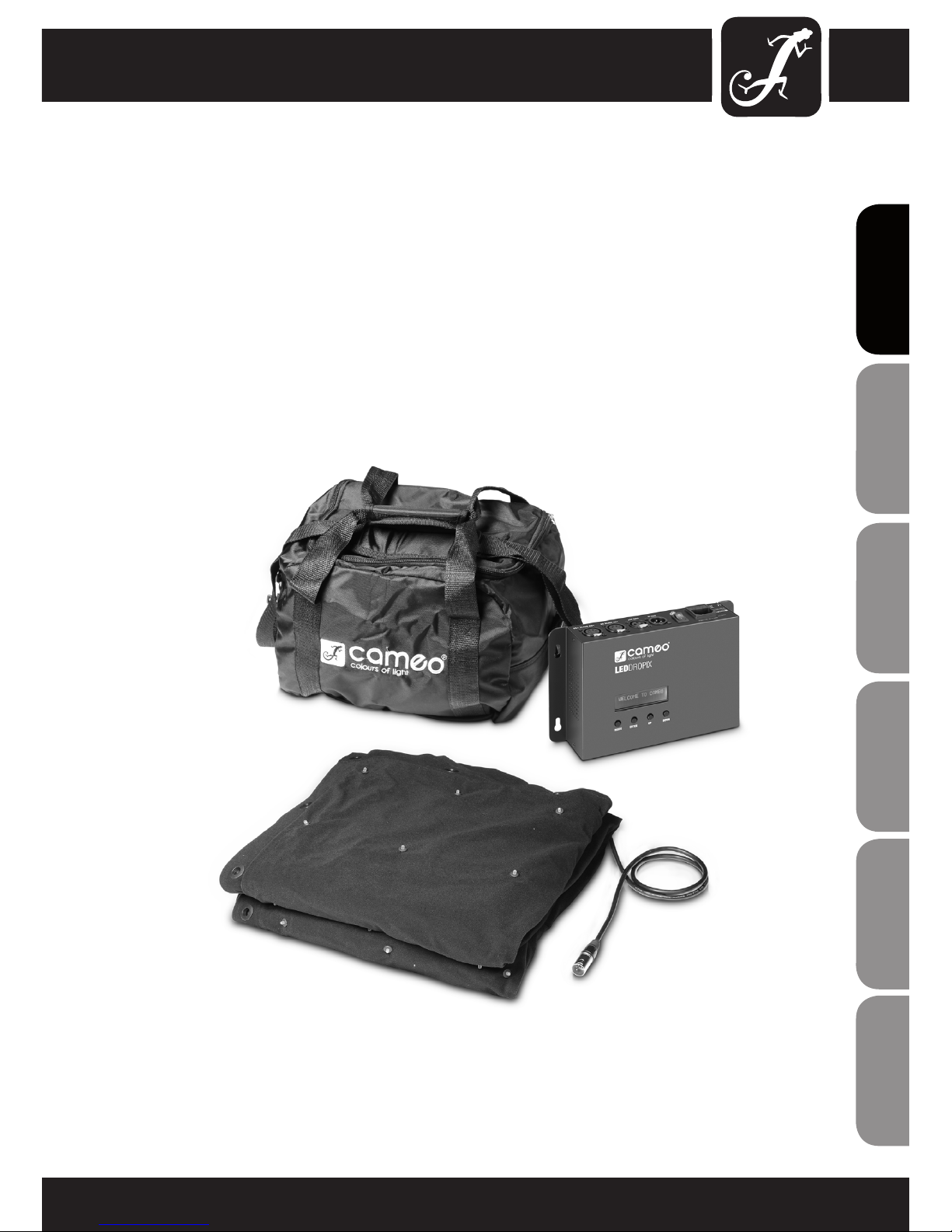
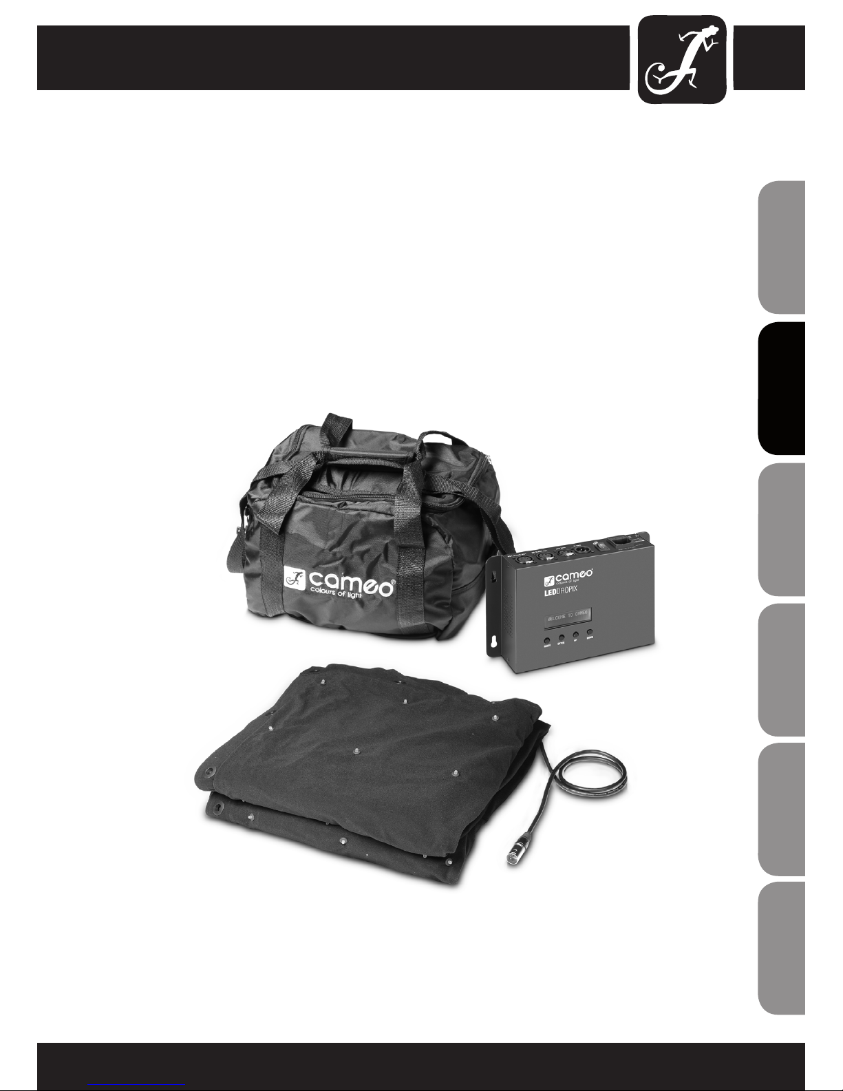
CLDROPIX66
Set consists of:
• 1 x LED curtain with 66 RGB LEDs (2 x 1.3 m) with connection cable
• 1 x Controller
• 1 x Power Cord
• 1 x Travel Bag
• 1 set of reusable cable ties
INTRODUCTION:
7
ITALIANOPOLSKIESPAÑOL
FRANCAISFRANCAIS FRANCAISFRANCAIS
FRANCAISDEUTSCHENGLISH

INTRODUCTION:
CLDROPIX176
Set consists of:
• 1 x LED curtain with 176 RGB LEDs (3.1 x 2 m) with connection cable
• 1 x Controller
• 1 x Power Cord
• 1 x Travel Bag
• 1 set of reusable cable ties
CLDROPIXSET
Set consists of:
• 1 x LED curtain with 66 RGB LEDs (2 x 1.3 m) with connection cable
• 1 x LED curtain with 176 RGB LEDs (3.1 x 2 m) with connection cable
• 1 x Extension cable 5 m CLDROPIXEXT5
• 1 x Controller
• 1 x Power Cord
• 1 x Travel Bag
• 1 set of reusable cable ties
CLDROPIXEXT5:
• 5 m extension cable for LED curtain
OPERATION:
The Cameo DROPIX LED curtains are DMX-512 controllable and can be operated in master/slave mode,
as a standalone unit, or by music control.
8
ENGLISHDEUTSCHFRANCAIS
FRANCAISFRANCAIS FRANCAISFRANCAIS
ESPAÑOLPOLSKIITALIANO

CONTROLLER, CONTROLS AND INDICATORS:
FRONT PANEL
LC DISPLAY
The lit LC display shows the operating mode and other system information.
CONTROL BUTTONS
MODE: exit the sub-menu
ENTER: Confi rm program selection and value changes.
UP and DOWN: Select a mode and a program, change the program speed and
set the DMX address.
1
2
1
2
9
ITALIANOPOLSKIESPAÑOL
FRANCAISFRANCAIS FRANCAISFRANCAIS
FRANCAISDEUTSCHENGLISH
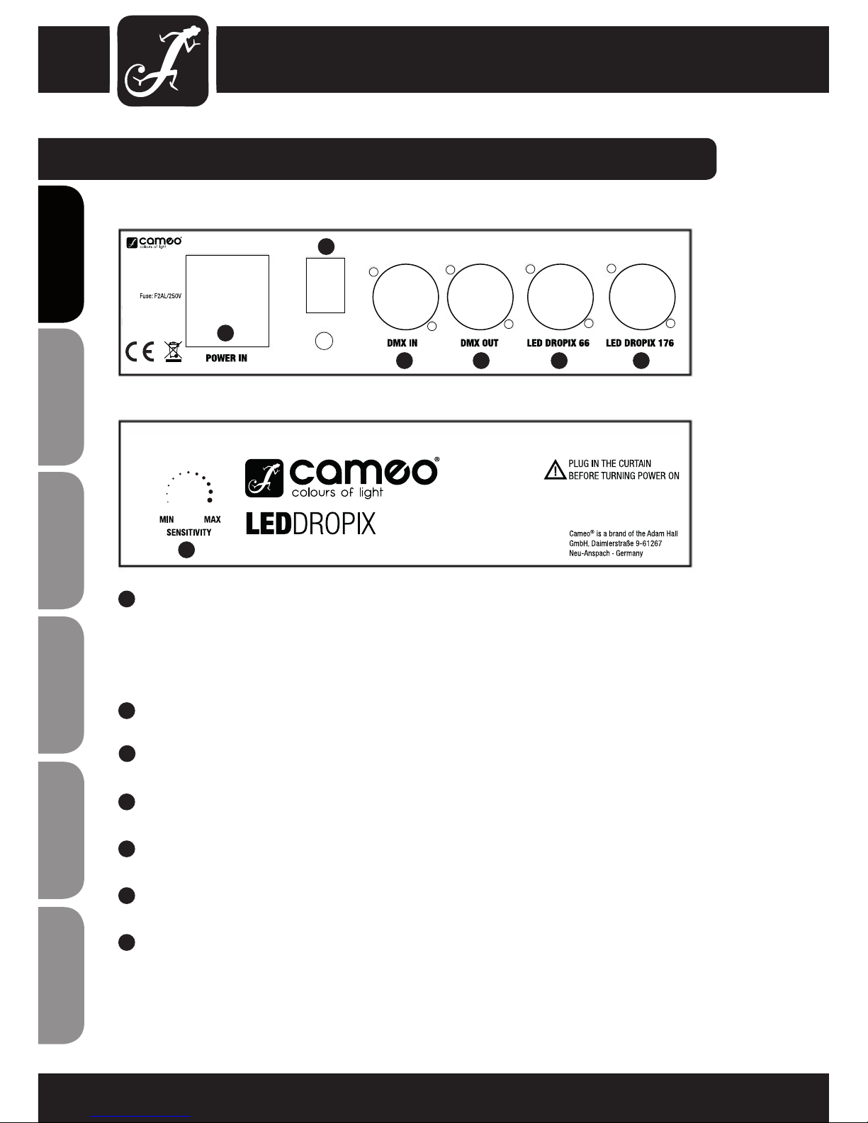
CONTROLLER, CONNECTIONS AND CONTROLS:
POWER IN
IEC power input socket with built-in fuse holder (voltage 220-240 V AC). Connection via the supplied IEC
mains cable.IMPORTANT NOTICE: Replace the fuse only with a fuse of the same type and rating. If the fuse
blows repeatedly, please contact an authorised service centre.
ON / OFF SWITCH
On / Off switch for the power supply of the device.
DMX IN
3-pin male XLR socket for connection of a DMX controller (e.g. DMX Mixer).
DMX OUT
3-pin XLR socket for looping through the DMX control signal.
LED DROPIX 66
Connector socket (4-pin XLR) for the 2 x 1.3 m large LED curtain with 66 RGB LEDs.
LED DROPIX 176
Connector socket (4-pin XLR) for the 3.1 x 2 m large LED curtain with 176 RGB LEDs.
SENSITIVITY
Controller for adjusting the microphone sensitivity in the music control mode (Sound Mode).
When turned to the left, the sensitivity is lowered, when turned to the right, it is increased.
CAUTION!
To avoid damage to the LED curtains or controller, always connect LED curtains before
using the controller!
3
4
5
7
AC 220V - 240V / 50Hz
Power Consumption: 50 W
6
8
9
3
4
5 6 7 8
9
10
ENGLISHDEUTSCHFRANCAIS
FRANCAISFRANCAIS FRANCAISFRANCAIS
ESPAÑOLPOLSKIITALIANO
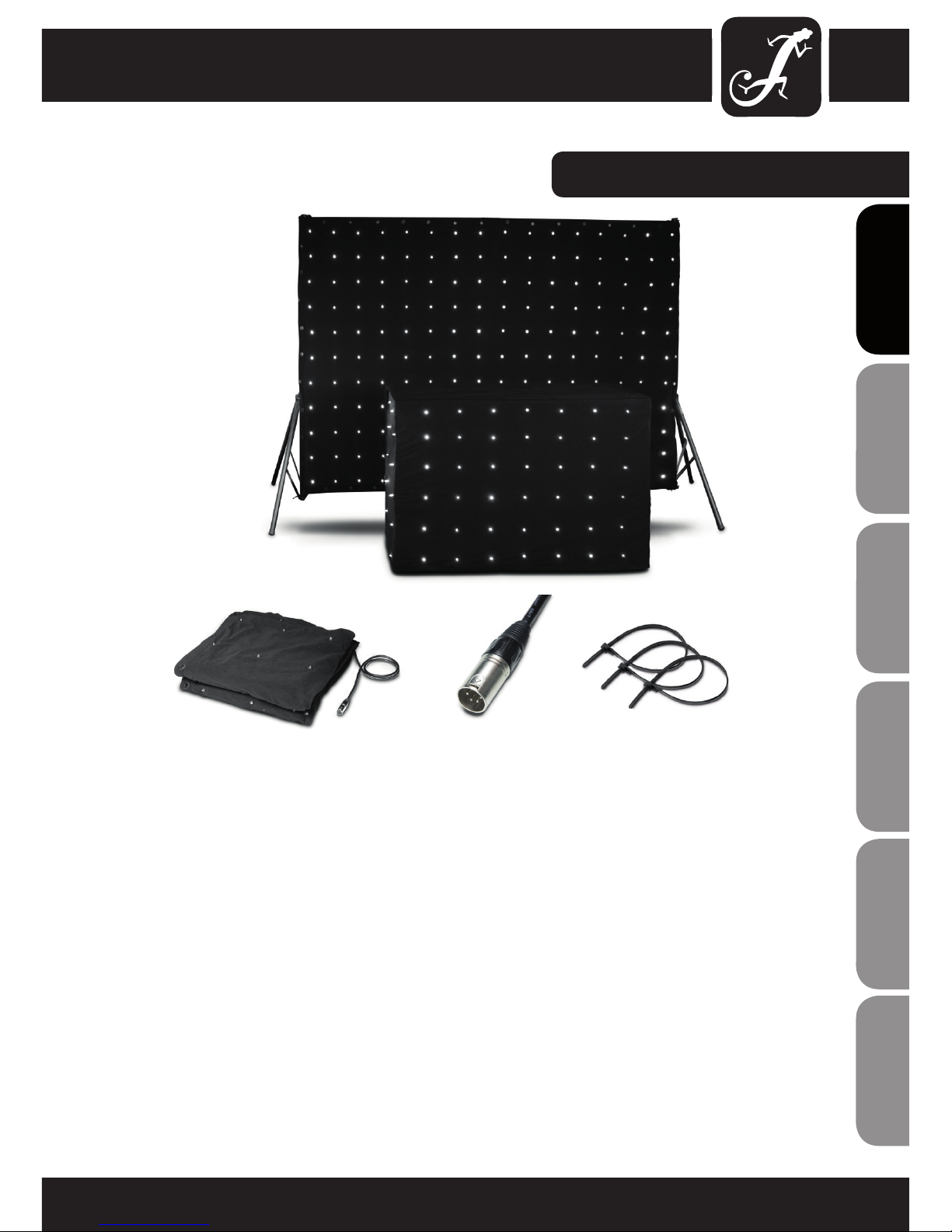
LED CURTAIN:
SETUP AND STARTUP:
Attach the 2 x 1.3 m (66 LEDs), or 3.1 x 2 m (176 LEDs) large LED curtain using the eyelets mounted on the
curtain hems and the supplied, reusable cable ties to a suitable stand or similar and smoothen the curtain fabric.
Take care not to bend the inner cable and do not step on the curtain to avoid damaging the installed LEDs and
electronics. Then connect the connection cable of the LED curtain to the corresponding connector of the controller
(2 x 1.3 m curtain with 66 LEDs to the connector LED DROPIX 66, 3.1 x 2 m curtain with 176 LEDs to the
connector LED DROPIX 176).
After that, operate the controller by connecting it to a suitable mains supply and switch on. You can now select
one of the internal programs, or operate the LEDDROPIX controller via a DMX control unit.
A 5 m extension cable, which is suitable for both curtains can be purchased as an optional accessory (CLDROPIXEXT5).
IMPORTANT WHEN REMOVING, PACKING, TRANSPORTING AND STORING:
Take care not to bend the inner cable of the LED curtains when disassembling and packing. Do not step on the
curtain to avoid damaging the installed LEDs and electronics. Carefully fold the LED curtains and place them in
the designated transport bags. During transportation and storage, do not place heavy objects on the transport
bags of the LED curtains.
11
ITALIANOPOLSKIESPAÑOL
FRANCAISFRANCAIS FRANCAISFRANCAIS
FRANCAISDEUTSCHENGLISH

EXTENSION CABLE:
CLDROPIXEXT5
5 m cable with 4-pin XLR male and 4-pin XLR female connectors used to extend the cable fixed on the LED curtains
DROPIX (available as optional accessory and included 1 x in CLDROPIXSET).
12
ENGLISHDEUTSCHFRANCAIS
FRANCAISFRANCAIS FRANCAISFRANCAIS
ESPAÑOLPOLSKIITALIANO

OPERATION:
NOTE:
Once the LEDDROPIX controller is properly connected and turned on, the
greeting "WELCOME TO CAMEO" is displayed for a short time during the boot
process. After this operation, the controller is ready for use and changes to the
mode that was previously selected.
AUTOMATIC CONTROL MODE (Auto Mode)
In the auto mode, one of the 30 different programs
(Program:01 - Program:30), plus a program where all 30 programs
run in sequence (Program:Mix) can be activated.
Press the MODE button several times if necessary to enter the upper menu of
the display. Now use the UP and DOWN buttons to select the Auto Mode and
confi rm by pressing the
ENTER button. The display now shows Auto Mode Speed.
By pressing the UP or DOWN button, select the menu item Auto Mode Pro-
gram. Confi rm with ENTER. The desired program can now be selected using
the UP and DOWN buttons (Program:01-30 and Program:Mix). Confi rm the input
with ENTER.
Set the running speed of the activated program by now pressing the UP
or DOWN buttons to select the menu item Auto Mode Speed. Confi rm with
ENTER and then using the UP and DOWN buttons, set the speed to the desired
value (Speed:00 = no movement in the program, Speed:01 = slowest speed,
Speed:99 = maximum speed). Confi rm with ENTER.
To permanently show a scene from a program, set the running speed of the
corresponding program to Speed:01 and at the moment in which the desired
scene is displayed, adjust the running speed to Speed:00. To enable another
program, the running speed must fi rst be set to a value other than Speed:00.
MUSIC CONTROL MODE (Sound Mode)
In the music control mode, the LED curtains are controlled via the built-in
microphone controller and the activated programs follow the beat of the music
(bass pulses). 30 different programs (Program:01 - Program:30), plus a program where all 30 programs run in sequence (Program:Mix), are available.
Press the MODE button several times if necessary to enter the the upper menu
of the display. Now use the UP and DOWN buttons to select the Sound Mode
and confi rm by pressing the
ENTER button.
The display now shows Sound Mode Program:xx. The desired program
can now be selected using the UP and DOWN buttons (Program:01-30 and
Program:Mix). Confi rm the input with ENTER.
To adjust the sensitivity with which the LED curtains react to music signals
(bass impulses), select SENSITIVITY on the LEDDROPIX controller. When turned
to the left, the sensitivity is lowered, when turned to the right, it is increased.
AC 220V - 240V / 50Hz
Power Consumption: 50 W
13
ITALIANOPOLSKIESPAÑOL
FRANCAISFRANCAIS FRANCAISFRANCAIS
FRANCAISDEUTSCHENGLISH
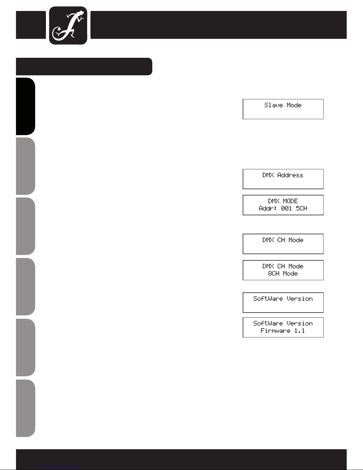
SLAVE MODE
Press the MODE button several times if necessary to enter the the upper menu
of the display. Now use the UP and DOWN buttons to select the Slave Mode
and confirm by pressing the
ENTER button.
Once the slave unit has been connected to the master unit (same model) using
a DMX cable (Master = DMX OUT, Slave = DMX IN), and the master unit has
been set to one of the standalone modes (automatic control or music control),
the slave unit follows the master unit.
SETTING THE DMX START ADRESS
Press the MODE button several times if necessary to enter the the upper menu
of the display. Now use the UP and DOWN buttons to select the DMX Address
and confirm by pressing the
ENTER button.
The display now shows DMX MODE Addr:xxx and one of the 3 available DMX
modes (3CH, 5CH, 8CH). Press the UP and DOWN buttons to select the desired
DMX start address (Addr:001 - Addr:512). Confirm the input with ENTER.
DMX mode (DMX CH mode)
Press the MODE button several times if necessary to enter the the upper menu
of the display. Now use the UP and DOWN buttons to select the DMX CH Mode
and confirm by pressing the ENTER button.
The display now shows DMX CH Mode and one of the 3 available DMX modes
(3CH Mode, 5CH Mode, 8CH Mode). The DMX mode can be adjusted as
desired by using the UP and DOWN buttons. Confirm the input with ENTER.
SOFTWARE VERSION
The software version of the DROPIX controller can be obtained by pressing the
MODE button (possibly several times) in the top menu level, then using the UP
and DOWN buttons, select the menu item Software Version. After you have
confirmed with ENTER, the software version is displayed as the firmware
version number.
NOTE:
The illumination of the LC display switches off automatically after approx. 30
seconds of inactivity. Pressing any one of the 4 control buttons will turn the
illumination of the LC display on again.
OPERATION:
14
ENGLISHDEUTSCHFRANCAIS
FRANCAISFRANCAIS FRANCAISFRANCAIS
ESPAÑOLPOLSKIITALIANO

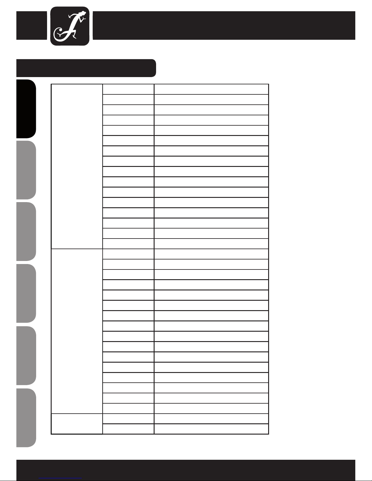
DMX CONTROL:
3-CHANNEL MODE
CHANNEL VALUE FUNCTION
CH1
000 - 007 No function
008 - 255 Red (0-100%)
CH2
000 - 007 No function
008 - 255 Green (0-100%)
CH3
000 - 007 No function
008 - 255 Blue (0-100%)
5-CHANNEL MODE
CHANNEL VALUE FUNCTION
CH1
000 - 007 No function
008 - 255 Master Dimmer
CH2
000 - 010 No function
011 - 255 Strobe (slow - fast)
CH3
000 - 007 No function
008 - 255 Red (0-100%)
CH4
000 - 007 No function
008 - 255 Green (0-100%)
CH5
000 - 007 No function
008 - 255 Blue (0-100%)
8-CHANNEL MODE
CHANNEL VALUE FUNCTION
CH1
000 - 007 No function
008 - 255 Master Dimmer
CH2
000 - 010 No function
011 - 255 Strobe (slow - fast)
CH3
000 - 007 No function
008 - 255 Red (0-100%)
CH4
000 - 007 No function
008 - 255 Green (0-100%)
CH5
000 - 007 No function
008 - 255 Blue (0-100%)
15
ITALIANOPOLSKIESPAÑOL
FRANCAISFRANCAIS FRANCAISFRANCAIS
FRANCAISDEUTSCHENGLISH
DMX CONTROL:
IMPORTANT:
When using the programs 01-30 in the 8-channel mode (channels 6 and 7) the master dimmer must be
(channel 1) set to 000 value. Channel 6 has priority over channel 7.
CH6
Master Dimmer
CH1 = 000
CH6 has priority
over CH7
000 - 015 No function
016 - 031 Program 1
032 - 047 Program 2
048 - 063 Program 3
064 - 079 Program 4
080 - 095 Program 5
096 - 111 Program 6
112 - 127 Program 7
128 - 143 Program 8
144 - 159 Program 9
160 - 175 Program 10
176 - 191 Program 11
192 - 207 Program 12
208 - 223 Program 13
224 - 239 Program 14
240 - 255 Program 15
CH7
Master Dimmer
CH1 = 000
CH6 has priority
over CH7
000 - 015 No function
016 - 031 Program 16
032 - 047 Program 17
048 - 063 Program 18
064 - 079 Program 19
080 - 095 Program 20
096 - 111 Program 21
112 - 127 Program 22
128 - 143 Program 23
144 - 159 Program 24
160 - 175 Program 25
176 - 191 Program 26
192 - 207 Program 27
208 - 223 Program 28
224 - 239 Program 29
240 - 255 Program 30
CH8
000 - 255 Program speed
(slow - fast)
16
ENGLISHDEUTSCHFRANCAIS
FRANCAISFRANCAIS FRANCAISFRANCAIS
ESPAÑOLPOLSKIITALIANO

17
ITALIANOPOLSKIESPAÑOL
FRANCAISFRANCAIS FRANCAISFRANCAIS
FRANCAISDEUTSCHENGLISH
DMX-512
DMX (Digital Multiplex) is the name of a universal transmission protocol for communication between
corresponding devices and controllers. A DMX controller sends DMX data to the connected DMX device(s).
The DMX data is always transmitted as a serial data stream that is forwarded from one connected device to
the next via the "DMX IN" and "DMX OUT" connectors (XLR plug-type connectors) that are found on every
DMX-capable device. (Most controllers only have a DMX output.)
DMX CONNECTION:
DMX is the common "language" via which a very wide range of types and models of equipment from
various manufacturers can be connected with one another and controlled via a central controller, provided
that all of the devices and the controller are DMX-compatible. For optimum data transmission, it is
necessary to keep the connecting cables between the individual devices as short as possible. The order in
which the devices are integrated in the DMX network has no influence on addressing. Thus the device with
the DMX address 1 can be located at any position in the (serial) DMX chain: at the beginning, at the end
or somewhere in the middle. If the DMX address 1 is assigned to a device, the controller "knows" that it
should send all data allocated to address 1 to this device regardless of its position in the DMX network.
The Adam Hall 3 STAR, 4 STAR, and 5 STAR product ranges include an extensive selection of suitable
cables.
SERIAL CONNECTION OF MULTIPLE LIGHTS
1.) Connect the male 3-pole XLR connector of the DMX cable to the DMX output (female 3-pole socket) of
the first light or other DMX device.
2.) Connect the female 3-pole connector of the DMX cable connected to the first light to the DMX input
(male 3-pole socket) of the next DMX device. In like manner, connect the DMX output of this device to the
DMX input of the next device and repeat until all devices have been connected.
Please note that as a rule, DMX devices are connected in series and connections cannot be shared without
active splitters.
DMX CONNECTION:
18
ENGLISHDEUTSCHFRANCAIS
FRANCAISFRANCAIS FRANCAISFRANCAIS
ESPAÑOLPOLSKIITALIANO
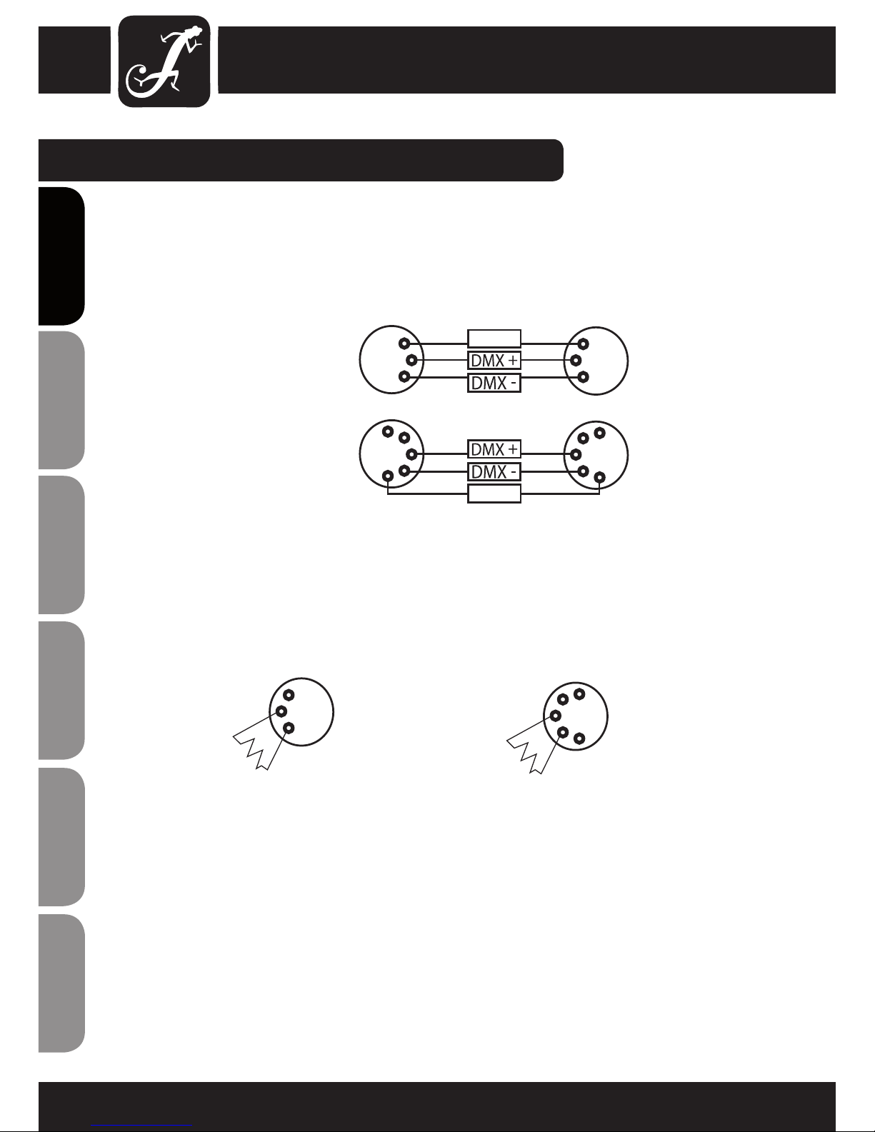
CABLES, TERMINATORS, ADAPTERS:
DMX CABLES:
When fabricating your own cables, always observe the illustrations on this page. Never connect the shielding
of the cable to the ground contact of the plug, and always make certain that the shielding does not come into
contact with the housing of the XLR plug. If the shielding is connected to the ground, this can lead to shortcircuiting and system malfunctions.
Pin Assignment:
DMX cable with 3-pin XLR connectors:
DMX cable with 5-pin XLR connectors:
DMX TERMINATORS (TERMINATING RESISTORS):
To prevent system errors, the last device in a DMX chain needs to be equipped with a terminating resistor (120
ohm, 1/4 Watt).
3-pin XLR connector with a terminating resistor: K3DMXT3
5-pin XLR connector with a terminating resistor: K3DMXT5
Pin Assignment:
3-pin XLR connector: 5-pin XLR connector:
Pins 4 and 5 are
not used.
Shield
2
3
1
2
3
1
1
2
3
4
5
1
2
3
4
5
Shield
2
3
1
1
2
3
4
5

19
ITALIANOPOLSKIESPAÑOL
FRANCAISFRANCAIS FRANCAISFRANCAIS
FRANCAISDEUTSCHENGLISH
CABLES, TERMINATORS, ADAPTERS:
Pin 4 und 5 sind nicht belegt.
Pin 4 und 5 sind nicht belegt.
DMX-ADAPTER:
Die Kombination von DMX-Geräten mit 3-Pol Anschlüssen und DMX-Geräten mit 5-Pol Anschlüssen in einer
DMX-Kette ist mit Hilfe von Adaptern ebenso möglich.
DMX-Adapter 5-Pol XLR male auf 3-Pol XLR female: K3DGF0020
Steckerbelegung
DMX-Adapter 3-Pol XLR male auf 5-Pol XLR female: K3DHM0020
Steckerbelegung
1
2
3
4
5
Shield
2
3
1
2
3
1
1
2
3
4
5
Shield

SPECIFICATIONS:
Model Name: CLDROPIX66
Product Type: LED effects set
Type: Matrix LED curtain
Set Contents: DROPIX controller + DROPIX curtain (2 x 1.3 m)
Other Features: travel bag included,
optional 5 m extension cable for curtain (CLDROPIXEXT5)
Model Name: CLDROPIX176
Product Type: LED effects set
Type: Matrix LED curtain
Set Contents: DROPIX controller + DROPIX curtain (3.1 x 2 m)
Other Features: travel bag included,
optional 5 m extension cable for curtain (CLDROPIXEXT5)
Model Name: CLDROPIXSET
Product Type: LED effects set
Type: Matrix LED curtain
Set Contents: DROPIX Controller
DROPIX Curtain (2 m x 1.3 m)
DROPIX Curtain (3.1 m x 2 m)
1 x extension cable for curtain (CLDROPIXEXT5)
Other Features: travel bag included,
optional 5 m extension cable for curtain (CLDROPIXEXT5)
20
ENGLISHDEUTSCHFRANCAIS
FRANCAISFRANCAIS FRANCAISFRANCAIS
ESPAÑOLPOLSKIITALIANO
Model Name: DROPIX Controller
DMX Input: 3-pin XLR male
DMX Output: 3-pin XLR female
Output for Curtain: 4-pin XLR female, DROPIX 66
4-pin XLR female, DROPIX 176
DMX Functions: RGB, Master Dimmer, 30 Matrix
Auto-Programs, Stroboscope
DMX Mode: 3-channel, 5-channel, 8-channel
Standalone Functions: 30 matrix auto programs, 30 matrix
sound programs, master/slave mode
Controls: Mode, Enter, Up, Down, On/Off, Micro-
phone Sensitivity
Indicators: backlit, 2-line LC display
Power Connector: IEC power socket
Operating Voltage: 220 - 240 V AC / 50 Hz
Power Consumption: 50 W
Fuse: F2AL / 250 V
Operating Temperature: 0°C - 45°C
Relative Humidity: up to 75%, non-condensing
Housing Material: metal
Housing Colour: black
Housing Cooling: convection
Controller Dimensions (W x H x D): 246 x 55 x 150 mm
Controller Weight: 1.1 kg
Controller Accessories: power cable
SPECIFICATIONS:
21
ITALIANOPOLSKIESPAÑOL
FRANCAISFRANCAIS FRANCAISFRANCAIS
FRANCAISDEUTSCHENGLISH
Model Name: CLDROPIXEXT5
Product Type: extension cable
Type: Connection between DROPIX controller and DROPIX
curtain
Connector: 4-pin XLR female, 4-pin XLR male
Cable Colour: black
Cable Length: 5 m
DROPIX LED Curtain (2 m x 1.3 m)
Colour Spectrum: RGB
Number of LEDs: 66
LED Type: SMD 3in1 LED
Curtain Fabric: hemmed curtain fabric with eyelets on all 4 sides, eyelet
interval 20 cm (B1 curtain fabric, flame resistant accord-
ing to DIN 4102-1).
Curtain Colour: black, opaque
Control: fixed mounted cable with 4-pin XLR Plug, 1.3 m
Curtain Dimensions (W x H x D): 2 x 1.3 m
Curtain Weight: 1.8 kg
Curtain Accessories: 1 set of replacement LEDs, 1 replacement cable set, 1
set of reusable cable ties for mounting
DROPIX LED curtain (3.1 m x 2 m)
Colour Spectrum: RGB
Number of LEDs: 176
LED Type: SMD 3in1 LED
Curtain Fabric: hemmed curtain fabric with eyelets on all 4 sides, eyelet
interval 20 cm (B1 curtain fabric, flame resistant accord-
ing to DIN 4102-1).
Curtain Colour: black, opaque
Control: fixed mounted cable with 4-pin XLR Plug, 1.3 m
Curtain Dimensions (W x H x D): 3.1 x 2 m
Curtain Weight: 4.5 kg
Curtain Accessories: 1 set of replacement LEDs, 1 replacement cable set, 1
set of reusable cable ties for mounting
SPECIFICATIONS:
22
ENGLISHDEUTSCHFRANCAIS
FRANCAISFRANCAIS FRANCAISFRANCAIS
ESPAÑOLPOLSKIITALIANO
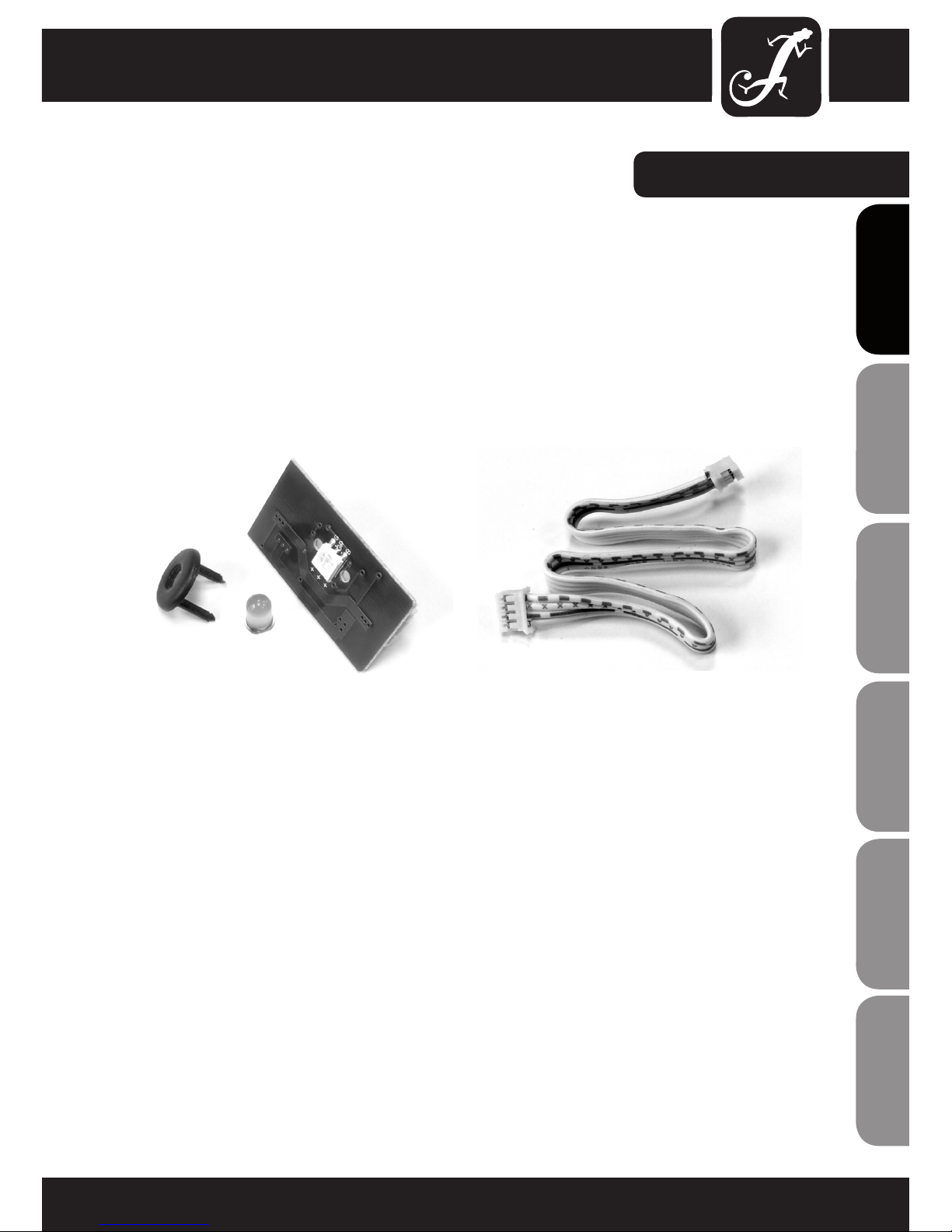
REPAIRS TO BE CARRIED OUT EXCLUSIVELY BY QUALIFIED PERSONNEL!
Instructions for the exchange of LED modules and connecting cables in the LED curtains (2 x 1.3 m and 3.1 m x
2 m):
Each DROPIX unit (CLDROPIX66, CLDROPIX176, CLDROPIXSET) contains both 1 spare set of LEDs and 1 spare
set of connection cable. Before a repair, the connected controller must be disconnected completely from the
mains supply (pull out the power cord).
In case of failure of an LED module or connecting cable, the respective spare parts should be inserted in the
same way as the original part. The LED curtains are equipped with zips on 3 sides, which allow for easy opening.
SERVICE:
23
ITALIANOPOLSKIESPAÑOL
FRANCAISFRANCAIS FRANCAISFRANCAIS
FRANCAISDEUTSCHENGLISH

24
ENGLISHDEUTSCHFRANCAIS
FRANCAISFRANCAIS FRANCAISFRANCAIS
ESPAÑOLPOLSKIITALIANO
MANUFACTURER‘S WARRANTY
This warranty extends to the CAMEO branded product you purchased from Adam Hall. The statutory warranty rights
against the vendor shall not be affected by this warranty. Rather, this warranty gives you additional independent
claims against Adam Hall.
With this warranty, Adam Hall ensures that products you have purchased from Adam Hall or Adam Hall partners,
under normal use, are free of defects in material or workmanship for a period of 2 years from the date of purchase.
The warranty period begins on the date of purchase. In order to assert a claim for warranty service, the proof of
date of purchase is provided by the receipt bearing the date of purchase or the date of purchase on the delivery
note. You are entitled to warranty service under the conditions and provisions set out in this document, if a repair
within the warranty period is required.
This warranty applies only to the original purchaser of the products supplied by Adam Hall and is not transferable
to any person to whom the property is transferred by the original purchaser.
Within the warranty period, the defective parts or the product from Adam Hall will be repaired or replaced. Under
the terms of this warranty, all the replaced or removed components become the property of Adam Hall.
In the unlikely event that a product acquired from Adam Hall, repeatedly exhibits a defect, Adam Hall may decide,
at its discretion, to replace this product with a comparable product of at least the same performance.
Adam Hall does not guarantee that the operation of this product will be uninterrupted or error-free. Adam Hall
accepts no responsibility for any damage due to incorrect compliance with the instructions received in the delivery.
This warranty does not extend to:
- wearing parts (eg battery, laser diodes).
- devices that have had their serial number removed or damaged, or failed as a result of an accident
- inappropriate or abusive use or other external causes
- devices that were not used in accordance with the operating parameters defined in the user documentation
shipped with the product
- devices that have been repaired using parts not made or distributed by Adam Hall
- devices that have been serviced, modified or repaired by someone other than Adam Hall or an authorised service partner.
These terms and conditions constitute the complete and exclusive warranty agreement between you and Adam
Hall regarding the Adam Hall branded product you have purchased.
This warranty is valid only within Europe. Outside of Europe please contact our official distributors.
MANUFACTURER´S DECLARATIONS:
25
ITALIANOPOLSKIESPAÑOL
FRANCAISFRANCAIS FRANCAISFRANCAIS
FRANCAISDEUTSCHENGLISH
MANUFACTURER´S DECLARATIONS:
LIMITATION OF LIABILITY
If your Adam Hall branded hardware product fails to work as warranted above, your sole and exclusive remedy
shall be repair or replacement. Adam Halls’ maximum liability under this limited warranty is expressly limited to
the lesser of the price you have paid for the product or the cost of repair or replacement of any components that
malfunction under conditions of normal use.
Adam Hall is not liable for any damages caused by the product or the failure of the product, including any lost
profits or savings or special, incidental, or consequential damages. Adam Hall is not liable for any claim made by
a third party or made by you for a third party.
This limitation of liability applies whether damages are sought, or claims are made, under this Limited Warranty
or as a tort claim (including negligence and strict product liability), a contract claim, or any other claim, and
cannot be rescinded or changed by anyone. This limitation of liability will be effective even if you have advised
Adam Hall or an authorized representative of Adam Hall of the possibility of any such damages, but not, however,
in the event of claims for damages in connection with personal injuries.
This manufacturer‘s warranty grants you specific rights; depending on jurisdiction (nation or state), you may be
be entitled to additional claims. You are advised to consult applicable state or national laws for a full determination of your rights.
REQUESTING WARRANTY SERVICE
To request warranty service for the product, contact Adam Hall or the Adam Hall authorized reseller from which
you purchased the product.
EC DECLARATION OF CONFORMITY
The equipment marketed by Adam Hall complies (where applicable) with the essential requirements and other
relevant specifications of Directives 1999/5/EC (R&TTE), 2004/108/EC (EMC) und 2006/95/EC (LVD). Additional
information can be found at www.adamhall.com.

26
ENGLISHDEUTSCHFRANCAIS
FRANCAISFRANCAIS FRANCAISFRANCAIS
ESPAÑOLPOLSKIITALIANO
PROPER DISPOSAL OF THIS PRODUCT
(Valid in the European Union and other European countries with waste separation)
This symbol on the product, or the documents accompanying the product, indicates that this appliance may not
be treated as household waste. This is to avoid environmental damage or personal injury due to uncontrolled
waste disposal. Please dispose of this product separately from other waste and have it recycled to promote
sustainable economic activity.
Household users should contact either the retailer where they purchased this product, or their local government
office, for details on where and how they can recycle this item in an environmentally friendly manner.
Business users should contact their supplier and check the terms and conditions of the purchase contract. This
product should not be mixed with other commercial wastes for disposal .
ENVIRONMENTAL PROTECTION AND ENERGY CONSERVATION
Energy conservation is an active contribution to environmental protection. Please turn off all unneeded electrical
devices. To prevent unneeded devices from consuming power in standby mode, disconnect the mains plug.
Adam Hall GmbH, all rights reserved. The technical data and the functional product characteristics can be subject
to modifications. The photocopying, the translation, and all other forms of copying of fragments or of the integrlity
of this user’s manual is prohibited.
MANUFACTURER´S DECLARATIONS:

27
ITALIANOPOLSKIESPAÑOL
FRANCAISFRANCAIS FRANCAISFRANCAIS
FRANCAISDEUTSCHENGLISH
Einleitung
Die mobilen LED-Vorhänge LED DROPIX 66 und LED DROPIX 176 von Cameo Light erzeugen 30 eindrucksvolle
Matrix-Effekte mit RGB-Farbmischung und weitem Abstrahlwinkel.
Die besonders hellen und langlebigen Tri-Color SMD-LEDs sind in 18cm Abständen auf blickdichtem Molton
angeordnet, das zur bequemen Aufhängung rundum geöst und nach DIN4102 B1 zertifiziert ist.
ENGLISHDEUTSCHFRANCAIS
FRANCAISFRANCAIS FRANCAISFRANCAIS
ESPAÑOLPOLSKIITALIANO
28
Wir freuen uns, dass Sie sich für ein Produkt von Cameo Light entschieden haben!
Dieses Gerät wurde unter hohen Qualitätsanforderungen entwickelt und gefertigt, um viele Jahre einen
reibungslosen Betrieb zu gewährleisten.
Bitte lesen Sie diese Bedienungsanleitung sorgfältig, damit Sie Ihr neues DMX-Gerät von Cameo Light schnell
optimal einsetzen können.
Weitere Informationen über Cameo Light erhalten Sie auf unserer Website WWW.CAMEOLIGHT.COM.
LED DROPIX 66 / 176 / SET
CLDROPIX66
CLDROPIX176
CLDROPIXSET
CLDROPIXEXT5
ITALIANOPOLSKIESPAÑOL
FRANCAISFRANCAIS FRANCAISFRANCAIS
FRANCAISDEUTSCHENGLISH
29

ENGLISHDEUTSCHFRANCAIS
FRANCAISFRANCAIS FRANCAISFRANCAIS
ESPAÑOLPOLSKIITALIANO
30
11. Das Gerät wurde ausschließlich für die Verwendung in Innenräumen entwickelt, betreiben Sie das Gerät nicht
in unmittelbarer Nähe von Wasser (gilt nicht für spezielle Outdoor Geräte - beachten Sie in diesem Fall bitte die im
Folgenden vermerkten Sonderhinweise). Bringen Sie das Gerät nicht mit brennbaren Materialien, Flüssigkeiten oder
Gasen in Berührung.
SICHERHEITSHINWEISE:
1. Lesen Sie diese Anleitung bitte sorgfältig durch.
2. Bewahren Sie alle Informationen und Anleitungen an einem sicheren Ort auf.
3. Befolgen Sie die Anweisungen.
4. Beachten Sie alle Warnhinweise. Entfernen Sie keine Sicherheitshinweise oder andere Informationen vom Gerät.
5. Verwenden Sie das Gerät nur in der vorgesehenen Art und Weise.
6. Verwenden Sie ausschließlich stabile und passende Stative bzw. Befestigungen (bei Festinstallationen). Stellen
Sie sicher, dass Wandhalterungen ordnungsgemäß installiert und gesichert sind. Stellen Sie sicher, dass das
Gerät sicher installiert ist und nicht herunterfallen kann.
7. Beachten Sie bei der Installation die für Ihr Land geltenden Sicherheitsvorschriften.
8. Installieren und betreiben Sie das Gerät nicht in der Nähe von Heizkörpern, Wärmespeichern, Öfen oder
sonstigen Wärmequellen. Sorgen Sie dafür, dass das Gerät immer so installiert ist, dass es ausreichend gekühlt
wird und nicht überhitzen kann.
9. Platzieren Sie keine Zündquellen wie z.B. brennende Kerzen auf dem Gerät.
10. Lüftungsschlitze dürfen nicht blockiert werden.
12. Sorgen Sie dafür, dass kein Tropf- oder Spritzwasser in das Gerät eindringen kann. Stellen Sie keine mit
Flüssigkeit gefüllten Behältnisse wie Vasen oder Trinkgefäße auf das Gerät.
13. Sorgen Sie dafür, dass keine Gegenstände in das Gerät fallen können.
14. Betreiben Sie das Gerät nur mit dem vom Hersteller empfohlenen und vorgesehenen Zubehör.
15. Öffnen Sie das Gerät nicht und verändern Sie es nicht.
16. Überprüfen Sie nach dem Anschluss des Geräts alle Kabelwege, um Schäden oder Unfälle, z. B. durch
Stolperfallen zu vermeiden.
17. Achten Sie beim Transport darauf, dass das Gerät nicht herunterfallen und dabei möglicherweise Sach- und
Personenschäden verursachen kann.
18. Wenn Ihr Gerät nicht mehr ordnungsgemäß funktioniert, Flüssigkeiten oder Gegenstände in das Geräteinnere
gelangt sind, oder das Gerät anderweitig beschädigt wurde, schalten Sie es sofort aus und trennen es von der
Netzsteckdose (sofern es sich um ein aktives Gerät handelt). Dieses Gerät darf nur von autorisiertem Fachpersonal repariert werden.
19. Verwenden Sie zur Reinigung des Geräts ein trockenes Tuch.
20. Beachten Sie alle in Ihrem Land geltenden Entsorgungsgesetze. Trennen Sie bei der Entsorgung der Verpackung bitte Kunststoff und Papier bzw. Kartonagen voneinander.
21. Kunststoffbeutel müssen außer Reichweite von Kindern aufbewahrt werden.
BEI GERÄTEN MIT NETZANSCHLUSS:
22. ACHTUNG: Wenn das Netzkabel des Geräts mit einem Schutzkontakt ausgestattet ist, muss es an einer
Steckdose mit Schutzleiter angeschlossen werden. Deaktivieren Sie niemals den Schutzleiter eines Netzkabels.
23. Schalten Sie das Gerät nicht sofort ein, wenn es starken Temperaturschwankungen ausgesetzt war (beispielsweise nach dem Transport). Feuchtigkeit und Kondensat könnten das Gerät beschädigen. Schalten Sie das
Gerät erst ein, wenn es Zimmertemperatur erreicht hat.
24. Bevor Sie das Gerät an die Steckdose anschließen, prüfen Sie zuerst, ob die Spannung und die Frequenz
des Stromnetzes mit den auf dem Gerät angegebenen Werten übereinstimmen. Verfügt das Gerät über einen
 Loading...