

Page 1
RADIOCOMANDI | RADIO CONTROLS | RADIOMANDOS
Documentazione
Tecnica
SISTEMA
UNIVERSAL
SISTEMA
ITALIANO
KIT RICEVITORE RADIO
MULTIUSO 433.92 PER ESTERNO
A 230V A.C. CON TRASMETTITORI
QUADRICANALE
IL KIT COMPRENDE:
- n°1 RBE42__Ricevitore radio
quadricanale per esterni a
230V, completo di scheda di
radiofrequenza AF43S.
- n°2 TOP-434NA__Trasmettitori quadricanale;
- n°1 TOP-A433N__Antenna
con staffa di fi ssaggio;
- n°1 TOP-RG58__Cavo coassiale per antenna (5 m).
RICEVITORE RADIO UNIVERSALE
RADIO RECEIVER SYSTEM
RECEPTOR RADIO UNIVERSAL
ENGLISH
SET RADIO RECEIVER
MULTIUSAGE 433.92 FOR
EXTERNAL AT 230V A.C. WITH 4
CHANNEL TRANSMITTERS
SET COMPOSITION:
- n°1 RBE42__Four-channel
external radio receiver, at 230V
a.c. with radiofrequency board
AF43S installed.
- n°2 TOP434NA__Four channel transmitters;
- n°1 TOP-A433N__Antenna
with anchor bracket;
- n°1 TOP-RG58__Coaxial
cable for antenna (5 m).
TRA08
ESPAÑOL
KIT RECEPTOR MULTIUSO 433.92
PARA MONTAJE EXTERNO, A 230V
A.C. CON TRANSMISOR DE CUADRO
CANALES
EL KIT INCLUYE:
- n°1 RBE42__Receptor de
cuadro canales para montaje externo, de 230V a.c., dotado de tarjeta de radiofrecuencia AF43S.
- n°2 TOP434NA__Transmisor
de cuatro canales;
- n°1 TOP-A433N__Antena con
soporte de fi jación;
- n°1 TOP-RG58__Cable
coaxial para antena (5 m).
U01
rev. 0.1
03/2006
© CAME
CANCELLI
AUTOMATICI
119RU01-1
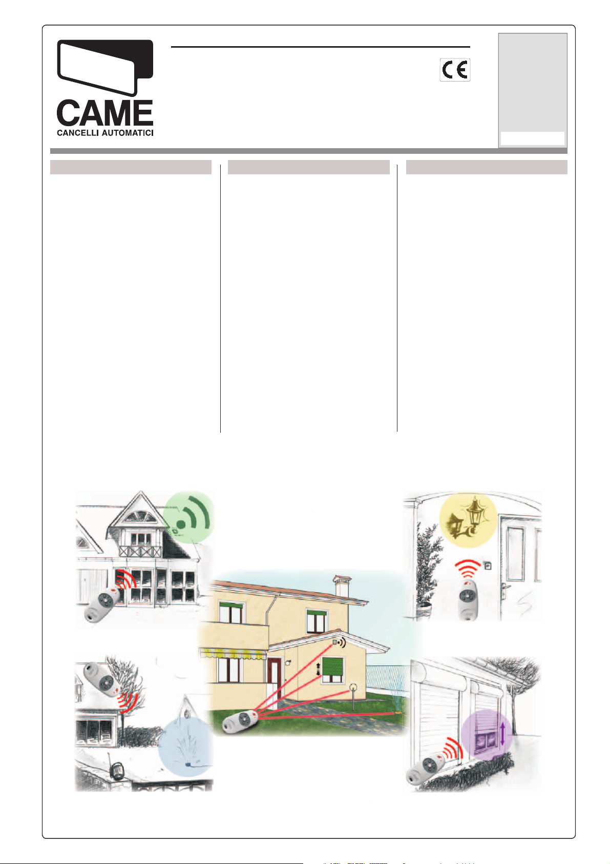
Per attivare l’allarme, ...
To activate alarm, ...
Para activar la alarma, ...
... accendere le luci esterne, ...
... turn on the external lights, ...
... encender las luces exteriores, ...
1
RADIOCOMANDO
RADIO TRANSMITTER
RADIOMANDO
... aprire l’impianto di irrigazione ...
.. start up of irrigation plant ...
... abrir la instalación de riego ...
4
IMPIANTI CONTROLLATI
CONTROLLED INSTALLATIONS
INSTALACIONES CONTROLADAS
... o chiudere le tapparelle.
... or close the rolling shutters.
... o cerrar las persianas.
Page 2
ITALIANO ENGLISH
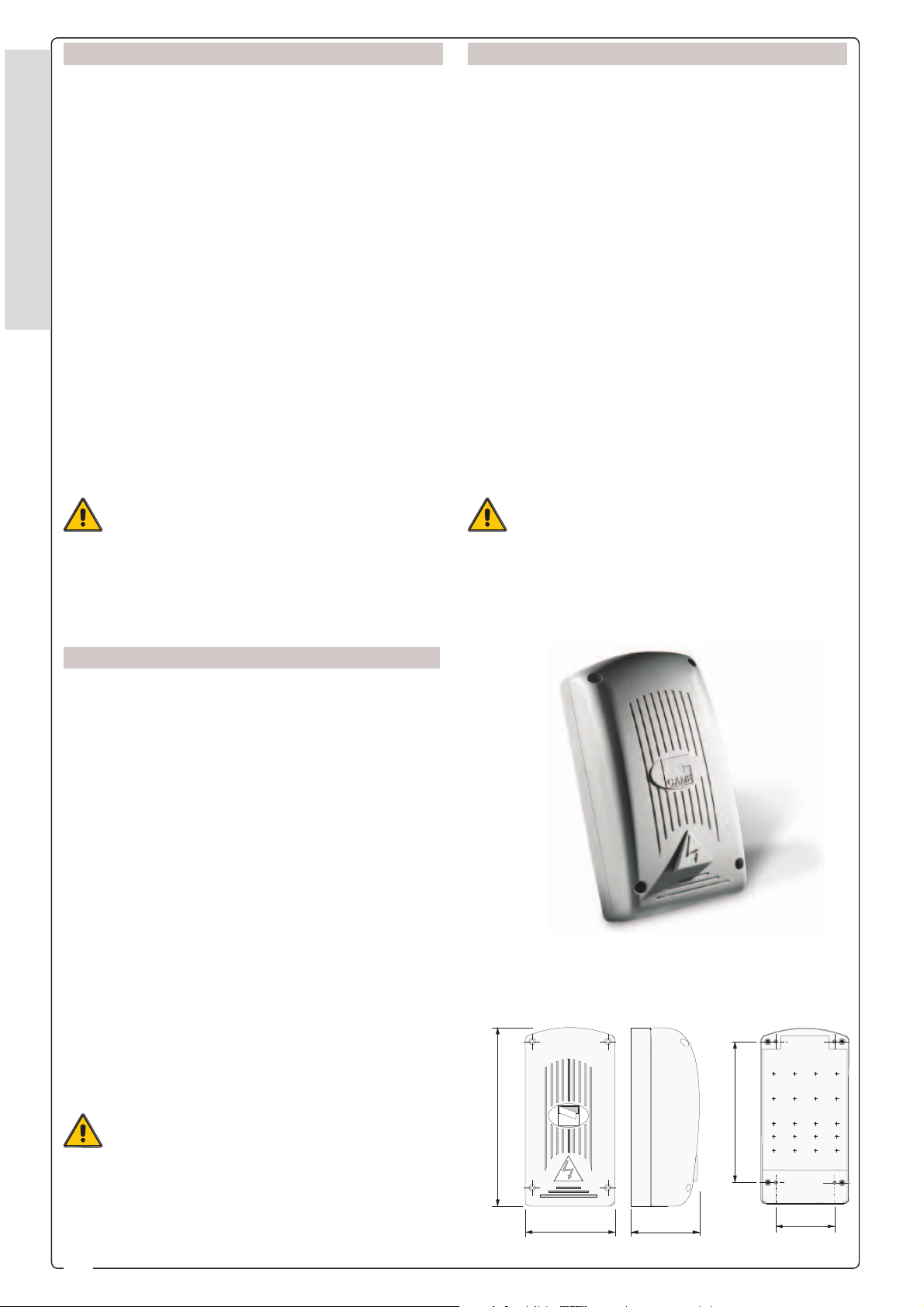
RBE42
Ricevitore radio a 4 canali da esterno.
Progettato e costruito interamente dalla CAME, è
garantito 24 mesi salvo manomissioni.
Contenitore in ABS da esterno con grado di pro-
tezione IP54.
La scheda va alimentata a 230V a.c.
Funzioni selezionabili per ogni singola uscita:
ITALIANO - ENGLISH - ESPAÑOL
- Funzione “azione mantenuta”
- Bistabile (interruttore)
- Monostabile temporizzato fi sso 3”
- Monostabile temporizzato fi sso 5’
Attenzione! Prima di interve nire all’interno
dell’apparecchiatura, togliere la tensione di
linea.
- É buona norma posizionare l’antenna il più alto possibile dal livello terra e lontana da strutture metalliche e
in cemento armato.
RBE42
Four-channel external radio receiver.
Fully designed and manufactured by CAME, it is
guaranteed for 24 months unless tampered with.
Container made of external-use ABS with IP54
protection level.
The board should be powered at 230V a.c.
Selectable functions for each single output:
- “Maintained Action” operation
- Bistable (switch)
- 3” timed fi xed monostable
- 5’ timed fi xed monostable
Important! Disconnect the unit from the main
power lines before carrying out any operation
inside the unit.
- It is good practice to position the antenna as high as
possible from ground level, and as far away as possible from metallic structures in reinforced cement.
ESPAÑOL
RBE42
Receptor de 4 canales para montaje externo.
Diseñado y fabricado completamente por la fi rma
CAME. Tiene 24 meses de garantía salvo adulteraciones..
Caja de ABS para exteriores con clase de protección IP54.
La tarjeta se alimenta a 230V a.c.
Funciones seleccionables para cada una de las
salidas:
- Función “accionamiento continuo”
- Biestable (interruptor)
- Monoestable temporizado fi jo 3”
- Monoestable temporizado fi jo 5’
Misure d’ingombro e di fi ssaggio
Size and installation measurements
Medidas de fi jación y exteriores máximas
¡Atención! Antes de actuar dentro del aparato,
quitar la tensión de línea.
- Es buena regla que la posición de la antena sea lo más
alta posible con relación al nivel del suelo y esté lejos
de estructuras metálicas y de hormigón.
2
225 mm
CAME
115 mm
87 mm
180 mm
75 mm
Page 3
ITALIANO
ENGLISH
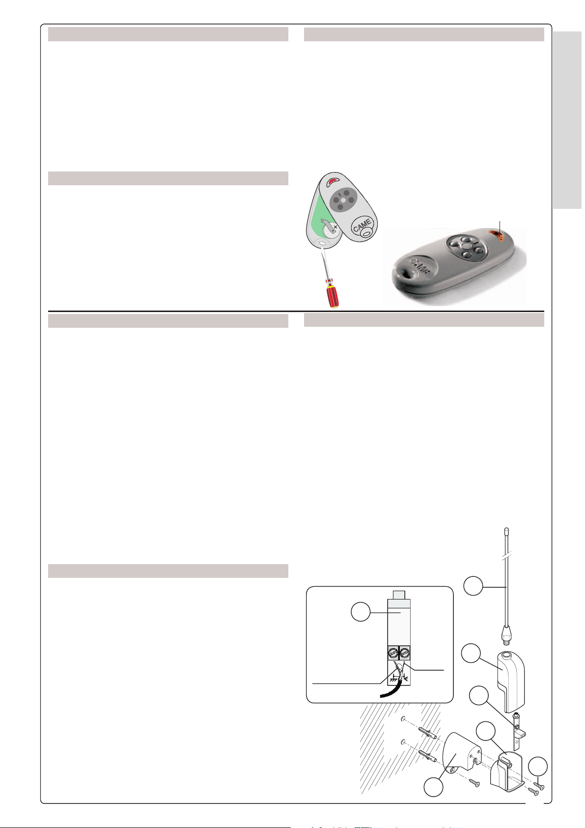
TOP-434NA
Trasmettitore quadricanale multiutenza.
Frequenza: AM 433.92 MHz
Batterie: n°2 CR2016 3V d.c. Lithium
Assorbimento in trasmissione: 12 mA
Portata: 50 ÷ 150 m
Combinazioni codice: 4096
Peso: 23 g
ESPAÑOL
TOP-434NA
Transmisor de cuatro canales.
Frecuencia: AM 433.92 MHz
Baterías: n°2 CR2016 3V d.c. Lithium
Consumo en trasmisión: 12 mA
Alcance: 50 ÷ 150 m
Combinaciones de código: 4096
Peso: 23 g
ITALIANO
TOP-A433N
1) Stelo antenna
2) Parte superiore contenitore
3) Circuito
4) Parte inferiore contenitore
5) Viti fi ssaggio antenna/staffa
6) Staffa di fi ssaggio
Descrizione del montaggio
- Fissare la parte inferiore del contenitore alla staffa di
fi ssaggio con le apposite viti.
- Collegare il cavo coassiale RG58 al morsetto del
circuito antenna.
- Inserire il circuito sulla parte inferiore del contenitore
tramite l’apposito foro posto sul circuito stesso.
- Incastrare i due contenitori tra di loro e avvitare lo
stelo.
TOP-434NA
Four-channel transmitter.
Frequency: AM 433.92 MHz
Batteries: n°2 CR2016 3V d.c. Lithium
Current draw in action: 12 mA
Range: 50 ÷ 150 m
Code combinations: 4096
Weight: 23 g
LED rosso di segnalazione
Signalling red LED
LED rojo de señalisation
ENGLISH
TOP-A433N
1) Antenna shaft
2) Upper section of casing
3) Circuit
4) Lower section of casing
5) Screws for fi xing aerial/brackets
6) Anchor bracket
Installation
- Fix the lower part of the container to the fi xing bracket
with the screws provided.
- Connect the coaxial cable RG58 to the terminal on the
antenna circuit.
- Insert the circuit into the lower part of the casing,
using the hole on the circuit it self.
- Fit the two parts of the casing together
and screw in the antenna shaft.
ITALIANO - ENGLISH - ESPAÑOL
ESPAÑOL
TOP-A433N
1) Varilla de la antena
2) Parte superior de la caja
3) Circuito
4) Parte inferior de la caja
5) Tornillos de fi jación de antena/soporte
6) Soporte de fi jación
Descripción del montaje
- Fije la parte inferior de la caja al soporte de fi jación con
los tornillos respectivos.
- Conecte el cable coaxial RG58 en el borne del circuito
de la antena.
- Conecte el circuito en la parte inferior de la caja a través
del orifi cio hecho en el mismo circuito.
- Encastre las dos partes de la caja y enrosque la varilla.
3
Calza
Wire shielding
Cable de tierra
Cavo
Cable
Cable
RG58
1
2
3
4
5
6
3
Page 4
ITALIANO
ENGLISH
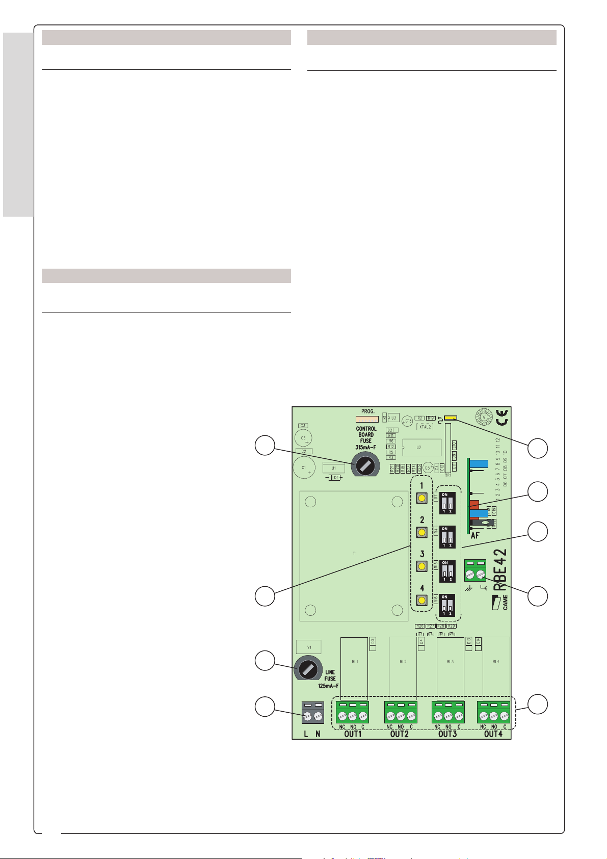
RBE42 - COMPONENTI PRINCIPALI
1) Fusibile centralina (315mA - rapido)
2) Pulsanti memorizzazione codice radio
3) Fusibile linea (125mA - rapido)
4) Morsettiera alimentazione 230V
5) Led segnalazione memorizzazione
6) Scheda radiofrequenza AF43S
7) Dip-switch selezione funzioni
ITALIANO - ENGLISH - ESPAÑOL
8) Morsettiera collegamento antenna
9) Morsettiere collegamento impianti (portata
max dei relè: 10A)
ESPAÑOL
RBE42 - COMPONENTES PRINCIPALES
1) Fusible central (315mA - rápido)
2) Botones memorización código radio
RBE42 - MAIN COMPONENTS
1) Control unit fuse (315mA - fast)
2) Buttons for storing radio code
3) Line fuse (125mA - fast)
4) 230V power line terminal
5) Storing signal Led
6) Radiofrequency board AF43S
7) Function selection dip-switches
8) Antenna connection terminal
9)
System connection terminal (max power
load of relays: 10A)
3) Fusible linea (125mA - rápido)
4) Caja de bornes alimentación 230V
5) Led señalización memorización
6) Tarjeta radiofrcuencia AF43S
7) Dip-switch selección funciones
8) Caja de bornes conexion antena
9) Caja de bornes conexion instalaciones (capacidad máx de los relés:
10A)
1
2
5
6
7
8
3
4
4
9
Page 5

21
ON
OFF
2
1
ON
OFF
2
1
ON
OFF
21
ON
OFF
ITALIANO
ENGLISH
PROCEDURA DI INSTALLAZIONE
A - Collegamenti elettrici
- Collegare i dispositivi da comandare sulle 4
uscite, selezionando per ognuna la funzione
desiderata;
- connettere l’antenna sul relativo morsetto con
il cavo RG58 (vedi pag. 3);
- alimentare la scheda con una tensione di linea
da 230V.
ESPAÑOL
PROCEDIMIENTO DE INSTALACIÓN
A - Conexions eléctricas
- Conectar los dispositivos para dar el mando
en las 4 salidas, seleccionando en cada una la
función deseada;
- conectar la antena en el relativo borne con el
cable RG58 (véase pág. 3);
- alimentar la tarjeta con una tensión de línea
de 230V.
INSTALLATION PROCEDURE
A - Electrical connections
- Connect the four devices to be controlled to
the 4 outputs, and for each one select the desired function;
- connect the antenna to the proper terminal using the RG58 cable (see p. 3);
- power the board with 230V voltage.
AF43S
RBE42
ITALIANO - ENGLISH - ESPAÑOL
TOPA433N
SELEZIONE FUNZIONI
(per ogni singola uscita)
SELECTION OF FUNCTIONS
(for each single output)
RG58
SELECCIÓN DE LA FUNCIONES
(para cada una de las salidas)
nzione “azione mantenuta”
Fu
“Maintained action” mode
Función “accionamiento continuo”
Monostabile temporizzato fi sso 3”
Monostable with fi xed 3” timing
Monoestable temporizado fi jo de 3”
Bistabile (interruttore)
Bistable (switch)
Biestable (interruptor)
AI DISPOSITIVI DA COMANDARE
(potenza max 250V a.c., con carico non
Monostabile temporizzato fi sso 5’
Monostable with fi xed 5’ timing
Monoestable temporizado fi jo de 5’
TO THE CONTROLLED DEVICES
(
max power 250V a.c. with non-inductive
induttivo)
power load)
ALIMENTAZIONE 230V A.C.
POWER SUPPLY 230V A.C.
ALIMENTACIÓN 230V A.C.
A LOS DISPOSITIVOS A ACCIONAR
(potencia máx 250V c.a., con carga no
inductiva)
5
Page 6

ITALIANO ENGLISH
PROCEDURA DI INSTALLAZIONE
B - Duplicare un trasmettitore
La duplicazione deve essere fatta perchè i trasmettitori sono fabbricati ciascuno con un codice diverso.
1 - premere assieme i primi 2 tasti fi no a quando il Led lampeggia più velocemente;
2 - premere ora il tasto da attivare (il Led si
accende);
ITALIANO - ENGLISH - ESPAÑOL
3 - entro 10”, appoggiare alla sua parte posteriore il trasmettitore attivo e premere per qualche
istante il tasto da duplicare.
A memorizzazione avvenuta, il LED lampeggierà
per 3 volte e il trasmettitore sarà pronto all’uso.
Ripetere i punti 1, 2 e 3 per i tasti rimanenti.
INSTALLATION PROCEDURE
B - Transmitter duplication
The duplication must be done because the transmitters are manufactured with a different code key by
key.
1 - press the fi rst 2 keys together until the LED
starts fl ashing more quickly;
2 - then press the key to activate (the LED comes on);
3 - within 10”, place the active transmitter on
its back and press the key to duplicate for a few
seconds.
After saving, the LED will fl ash 3 times and the
transmitter will be ready for use.
For another key, repeat steps 1, 2 and 3.
ESPAÑOL
PROCEDIMIENTO DE INSTALACIÓN
B - Duplique un transmisor
La duplicación debe efectuarse, porque cada transmisor es fabricado con un código diferente.
1 - pulse junto las primeras 2 botones hasta
que el Led parpadee más rápido;
2 - ahora pulse el botón a activar (el Led se
enciende);
3 - antes de transcurridos 10”, apoye sobre la
parte trasera el transmisor activo y pulse el botón a duplicar durante algunos segundos.
Una vez memorizado, el LED parpadeará 3 veces
y el transmisor estará listo para ser usado.
Repita los puntos 1, 2 y 3 para el otro botón.
1
2
3
6
Page 7

ITALIANO ENGLISH
PROCEDURA DI INSTALLAZIONE
C - Memorizzarlo sul ricevitore
Tenere premuto un tasto di memoriz zazione e,
quando il led di segnalazione lampeggia, premere il tasto del trasmettitore per inviare il codice.
Il led rimarrà acceso a segnalare l’avvenuta
memorizzazione.
Eseguire la stessa procedura per ogni uscita
(vedi anche esempi alle pagine successive).
ESPAÑOL
PROCEDIMIENTO DE INSTALACIÓN
C - Memorícelo en el receptor
Mantener apretada la tecla de memorización y
cuando el led de señalización parpadea, apretar
la tecla del transmisor para enviar el código.
El led quedará encendido para indicar que la
memorización se efectuó.
Repita el mismo procedimiento para cada salida
(véanse también los ejemplos en las páginas
siguientes).
INSTALLATION PROCEDURE
C - Code storage
Keep a memorisation button pressed and, when
the signal led blinks, press the transmitter button to send the code.
The LED will remain lit in order to confi rm that
storage has taken place.
Follow the same procedure for every output
(see also examples on the following pages).
LED di segnalazione codice radio
Radio code signalling LED
LED di señalización código radio
ITALIANO - ENGLISH - ESPAÑOL
1 => OUT1
2 => OUT2
3 => OUT3
4 => OUT4
7
Page 8

ITALIANO ENGLISH
ESEMPI DI APPLICAZIONI
La combinazione minima consente ad un tasto del
trasmettitore di comandare contemporaneamente le 4
uscite (vedi fondo pagina).
La combinazione massima prevede il comando
separato di ogni singolo canale con un tasto diverso
(vedi esempio A, pagina seguente)
.
Le combinazioni intermedie possono essere molte-
ITALIANO - ENGLISH - ESPAÑOL
plici (vedi esempi B e C, pagine 10 /11)
ESPAÑOL
EJEMPLO DE APLICACIONES
La combinación mínima permite
las 4 sali
das mediante una sola tecla del transmisor
.
controlar a la vez
(véase final página).
La combinación máxima supone el control por
separado de cad a uno de los canales mediante una tecla diferente (Véase ejemplo A, página si-
guiente).
Hay muchas combinaci
ones intermedias (Véase
ejemplos B y C, páginas 10/11).
EXAMPLES OF APPLICATIONS
The minimum combination allows one transmit-
ter key to control the 4 outputs at the same time (see
bottom of the page).
The maximum combination contemplates the
separate control of each individual channel with a
different key (see example A, on the next page).
There are several possible intermediate combinations (see examples B and C, pages 10 and 11).
P1
P3
P2
P4
P1 => 1 => OUT1
P1 => 3 => OUT3 P1 => 4 => OUT4
P1 => 2 => OUT2
8
Page 9

A
CONDOMINIO - CONDOMINIUM - INMUEBLE
P1 => 1 => OUT1
Sbarra condominio
Condominium barrier
Barrera edifi cio
P2 => 2 => OUT2
P1
P2
ITALIANO - ENGLISH - ESPAÑOL
E
M
A
E
C
M
A
C
Luci viale temporizzate
Timer-controlled light for access path
Luces externas temporizadas
Portone sezionale accesso zona garage
Sectional door for garage access
Puerta seccional entrada zona garages
P3 => 3 => OUT3
P1
P3
P2
P4
Luci scale ingresso temporizzate
Timer-controlled light for stairs/entrance
Luces escalera entrada temporizadas
P4 => 4 => OUT4
P3
P4
9
Page 10

B
CASA - HOUSE - CASA
ITALIANO - ENGLISH - ESPAÑOL
P1 => 1 => OUT1
Cancello scorrevole
Sliding gate
Puerta corredera
P2 => 2 => OUT2
P2
P1
Portone basculante
Overhead door
Puerta basculante
Luci viale temporizzate
Timer-controlled light for access path
Luces externas temporizadas
P4 => 3 => OUT3
P1
P3
P2
P4
Allarme
Alarm
Alarma
ALARM
P4 => 4 => OUT4
10
P4
P4
Page 11

C
CONDOMINIO - CONDOMINIUM - INMUEBLE
P2 => 1 => OUT1
Sbarra condominio
Condominium barrier
Barrera edifi cio
P4 => 2 => OUT2
P2
P4
ITALIANO - ENGLISH - ESPAÑOL
E
M
A
E
C
M
A
C
Portone basculante
Overhead door
Puerta basculante
Luci scale ingresso temporizzate
Timer-controlled light for stairs/entrance
Luces escalera entrada temporizadas
P3 => 3 => OUT3
P1
P3
P2
P4
P3
11
Page 12

ITALIANO ENGLISH ESPAÑOL
DICHIARAZIONE CE DI CONFORMITÀ
Ai sens i della Direttiva R &TTE 1999/5/CE
DECLARATION CE OF CONFORMITY
Pursuant to the R&TTE Directive 1999/5/EC
DECLARACIÓN CE DE CONFORMIDAD
De conformidad con la Directiva R&TTE 1999/ 5/ CE
CAME CANCELLI AUTOMATICI S.p.A.
Via Martiri della Libertà, 15
31030 Dosson di Casier
TREVISO - ITALY
Dichiara sotto la propria responsabilità,
che i seguenti prodotti per l’automazione
di cancelli e porte da garage, così
denominati:
KIT RICEVITORE RADIO MULTIUSO
TRA08
sono conformi ai requisiti essenziali ed
alle disposizioni pertinenti, stabilite dalle
seguenti Direttive e alle parti applicabili
delle Normative di riferimento in seguito
elencate:
1999/5/CE
Direttiva R&TTE
89/336/CEE - 92/31/CEE
Direttiva Compatibilità
Elettromagnetica
73/23/CEE
Direttiva Bassa Tensione
-----
ETSI 300 220-1
ETSI 300 220-3
ETSI 301 489-1
ETSI 301 489-3
EN 60335-1
EN 60950-1
CAME CANCELLI AUTOMATICI S.p.A.
Via Martiri della Libertà, 15
31030 Dosson di Casier
TREVISO - ITALY
Is fully liable in declaring that
the products for automatic
garage doors and gates listed
below:
SET RADIO RECEIVER MULTIUSAGE
TRA08
comply with the National
Law related to the following
European Directives and to the
applicable parts of the following
Standards:
1999/5/EC
R&TTE Directive
89/336/EEC - 92/31/EEC
Electromagnetic compatibility
Directive
73/23/ EEC
Low Voltage Directive
-----
ETSI 300 220-1
ETSI 300 220-3
ETSI 301 489-1
ETSI 301 489-3
EN 60335-1
EN 60950-1
CAME CANCELLI AUTOMATICI S.p.A.
Via Martiri della Libertà, 15
31030 Dosson di Casier
TREVISO - ITALY
Declara bajo su exclusiva responsabilidad,
que los siguientes productos para la
automatización de cancelas y puertas para
garajes, denominados del siguiente modo:
KIT RECEPTOR MULTIUSO
TRA08
son de conformidad con los requisitos
esenciales y las disposiciones pertinentes,
establecidos por las siguientes Directivas y
con las partes aplicables de las Normativas
de referencia que se indican a continuación:
1999/5/CE
Directiva R&TTE
89/336/CEE - 92/31/CEE
Directiva Compatibilidad
Electromagnética
73/23/CEE
Directiva Baja Tensión
-----
ETSI 300 220-1
ETSI 300 220-3
ETSI 301 489-1
ETSI 301 489-3
EN 60335-1
EN 60950-1
Dosson di Casier lì 17 marzo 2006
L’amministratore delegato
Andrea Menuzzo
Codice di riferimento per richiedere una copia
Tut ti i dati sono sta ti con trol la ti con la mas si ma cura.
Non ci as su mia mo co mun que al cu na re spon sa bi li tà per
even tua li errori od omissioni.
conforme all’originale:
DDF RA IT
Z001 Ver 1.0
ASSISTENZA TECNICA
NUMERO VERDE
800 295830
EB
W
www.came.it
MAIL
E-
info@came.it
CAME CANCELLI AUTOMATICI S.P.A.
OSSON DI CASIER (TREVISO)
D
(+39) 0422 4940 (+39) 0422 4941
SISTEMA QUALITÀ
CERTIFICATO
Dosson di Casier, 17th March 2006
The Managing Director
Andrea Menuzzo
Reference code to request a true copy of the
All data checked with the maximum care. However, no
liability is accepted for any error or omission.
CAME NORD S.R.L._______COLOGNO M. (MI)
(+39) 02 26708293 (+39) 02 25490288
CAME SUD S.R.L._________________NAPOLI
(+39) 081 7524455 (+39) 081 7529109
CAME (AMERICA) L.L.C.__________MIAMI (FL)
(+1) 305 5930227 (+1) 305 5939823
CAME AUTOMATISMOS S.A._________MADRID
(+34) 091 5285009 (+34) 091 4685442
CAME BELGIUM_________________LESSINES
(+32) 068 333014 (+32) 068 338019
original:
DDF RA GB
Z001 Ver 1.0
Dosson di Casier el 17 Marcha 2006
El administrador delegado:
Andrea Menuzzo
Código de referencia para solicitar una copia de
conformidad con la copia original:
DDF RA ES
Z001 Ver 1.0
Todos los datos se han controlado con la máxima
atención. No obstante no nos responsabilizamos de los
posibles errores u omisiones.
CAME FRANCE S.A.___NANTERRE CEDEX (PARIS)
(+33) 01 46130505 (+33) 01 46130500
CAME GMBH________K
(+49) 07 11839590 (+49) 07 118395925
CAME GMBH _____________S
(+49) 03 33988390 (+49) 03 339885508
CAME PL SP.ZO.O_______________WARSZAWA
(+48) 022 8365076 (+48) 022 8369920
CAME UNITED KINGDOM LTD___NOTTINGHAM
(+44) 01159 387200 (+44) 01159 382694
ORNTAL BEI (STUTTGART)
EEFELD BEI (BERLIN)
 Loading...