

Page 1

BXV
Installation manual
SDN4 - SDN6 - SDN8 - SDN10
OPERATOR
FOR SLIDING GATES
FA00014-EN
Eng
lis
h
Page 2

p.
2
2 - Manual code
FA0 0 0 14 -E N
FA00014-EN v.
3
3 04/2016 - © Came S.p.A. The contents of this manual may be changed at any time without prior notice.
WARNING!
Important safety instructions for people:
READ CAREFULLY!
FOREWORD
• THIS PRODUCT MUST ONLY BE USED FOR ITS INTENDED
PURPOSE. ANY OTHER USE IS DANGEROUS. CAME S.P.A.
I
S NOT LIABLE FOR ANY DAMAGE CAUSED BY IMPROPER,
WRONGFUL AND UNREASONABLE USE • KEEP THESE
WARNINGS TOGETHER WITH THE INSTALLATION AND
OPERATION MANUALS THAT COME WITH THE GEARMOTOR.
B
EFORE INSTALLING
(CHECKING WHAT'S THERE: IF YOUR EVALUATION IS NEGATIVE,
DO NOT PROCEED BEFORE HAVING COMPLIED WITH ALL
SAFETY REQUIREMENTS)
• C
HECK THAT THE AUTOMATED PAR TS ARE IN GOOD
MECHANICAL ORDER, THAT THE GEARMOTOR IS LEVEL AND
ALIGNED, AND THAT IT OPENS AND CLOSES PROPERLY.
M
AKE SURE YOU HAVE SUITABLE MECHANICAL STOPS •
IF THE GEARMOTOR IS TO BE INSTALLED AT A HEIGHT OF
OVER 2.5 M FROM THE GROUND OR OTHER ACCESS LEVEL,
MAKE SURE YOU HAVE ANY NECESSARY PROTECTIONS AND/
OR WARNINGS IN PLACE • IF ANY PEDESTRIAN OPENINGS
ARE FITTED INTO THE GEARMOTOR, THERE MUST ALSO BE A
A SYSTEM TO BLOCK THEIR OPENING WHILE THEY ARE MOVING
•
MAKE SURE THAT THE OPENING AUTOMATED DOOR OR
GATE CANNOT ENTRAP PEOPLE AGAINST THE FIXED PA RT S
OF THE GEARMOTOR • DO NOT INSTALL THE GEARMOTOR
UPSIDE DOWN OR ONTO ELEMENTS THAT COULD YIELD AND
BEND. IF NECESSARY, ADD SUITABLE REINFORCEMENTS TO
THE ANCHORING POINTS • DO NOT INSTALL DOOR OR GATE
LEAVES ON TILTED SURFACES • MAKE SURE ANY SPRINKLER
SYSTEMS CANNOT WET THE GEARMOTOR FROM THE GROUND
UP • MAKE SURE THE TEMPERATURE RANGE SHOWN ON
THE PRODUCT LITERATURE IS SUITABLE TO THE CLIMATE
WHERE IT WILL BE INSTALLED • FOLLOW ALL INSTRUCTIONS
AS IMPROPER INSTALLATION MAY RESULT IN SERIOUS BODILY
INJURY • IT IS IMPORTANT TO FOLLOW THESE INSTRUCTIONS
FOR THE SAFETY OF PEOPLE. KEEP THESE INSTRUCTIONS.
I
NSTALLING
• SUITABLY SECTION OFF AND DEMARCATE THE ENTIRE
INSTALLATION SITE TO PREVENT UNAUTHORIZED PERSONS
FROM ENTERING THE AREA, ESPECIALLY MINORS AND
CHILDREN • BE CAREFUL WHEN HANDLING GEARMOTORS
THAT WEIGH OVER 20 KG. IF NEED BE, USE PROPER SAFETY
HOISTING EQUIPMENT • ALL OPENING COMMANDS (THAT
IS, BUTTONS, KEY SWITCHES, MAGNETIC READERS, AND
SO ON) MUST BE INSTALLED AT LEAST 1.85 M FROM
THE PERIMETER OF THE GATE'S WORKING AREA, OR WHERE
THEY CANNOT BE REACHED FROM OUTSIDE THE GATE. ALSO,
ANY DIRECT COMMANDS (BUTTONS, TOUCH PANELS, AND
SO ON) MUST BE INSTALLED AT LEAST 1.5 M FROM THE
GROUND AND MUST NOT BE REACHABLE BY UNAUTHORIZED
PERSONS • ALL MAINTAINED ACTION COMMANDS, MUST BE
FITTED IN PLACES FROM WHICH THE MOVING GATE LEAVES
AND TRANSIT AND DRIVING AREAS ARE VISIBLE • APPLY, IF
MISSING, A PERMANENT SIGN SHOWING THE POSITION OF THE
RELEASE DEVICE • BEFORE DELIVERING TO THE USERS, MAKE
SURE THE SYSTEM IS EN 12453 STANDARD COMPLIANT
(
REGARDING IMPACT FORCES), AND ALSO MAKE SURE THE
SYSTEM HAS BEEN PROPERLY ADJUSTED AND THAT ANY
SAFETY, PROTECTION AND MANUAL RELEASE DEVICES ARE
WORKING PROPERLY • APPLY WARNING SIGNS (SUCH AS THE
GATE'S PLATE) WHERE NECESSARY AND IN A VISIBLE PLACE
S
PECIAL USER-INSTRUCTIONS AND RECOMMENDATIONS
• K
EEP GATE OPERATION AREAS CLEAN AND FREE OF
ANY OBSTRUCTIONS. MAKE SURE THAT THE PHOTOCELLS
ARE FREE OF ANY OVERGROWN VEGETATION AND THAT
THE GEARMOTOR'S AREA OF OPERATION IS FREE OF ANY
OBSTRUCTIONS • DO NOT ALLOW CHILDREN TO PLAY WITH
FIXED COMMANDS, OR TO LOITER IN THE GATE'S MANEUVERING
AREA. KEEP ANY REMOTE CONTROL TRANSMITTERS OR
ANY OTHER COMMAND DEVICE AWAY FROM CHILDREN,
TO PREVENT THE GEARMOTOR FROM BEING ACCIDENTALLY
ACTIVATED. • THE APPARATUS MAY BE USED BY CHILDREN
OF EIGHT YEARS AND ABOVE AND BY PHYSICALLY, MENTALLY
AND SENSORIALLY CHALLENGED PEOPLE, OR EVEN ONES
WITHOUT ANY EXPERIENCE, PROVIDED THIS HAPPENS UNDER
CLOSE SUPERVISION OR ONCE THEY HAVE BEEN PROPERLY
INSTRUCTED TO USE THE APPARATUS SAFELY AND ABOUT
THE POTENTIAL HAZARDS INVOLVED. CHILDREN MUST NOT
PLAY WITH THE APPARATUS. CLEANING AND MAINTENANCE
BY USERS MUST NOT BE DONE BY CHILDREN, UNLESS
PROPERLY SUPERVISED • FREQUENTLY CHECK THE SYSTEM
FOR ANY MALFUNCTIONS OR SIGNS OF WEAR AND TEAR OR
DAMAGE TO THE MOVING STRUCTURES, TO THE COMPONENT
PA RTS , ALL ANCHORING POINTS, INCLUDING CABLES AND
ANY ACCESSIBLE CONNECTIONS. KEEP ANY HINGES, MOVING
Page 3

p.
3
3 - Manual code
FA0 0 0 14 -E N
FA00014-EN v.
3
3
04/2016 - © Came S.p.A. The contents of this manual may be changed at any time without prior notice.
DANGER OF HAND CRUSHING
DANGER! HIGH VOLTAGE.
N
O TRANSITING WHILE THE BARRIER IS MOVING
DANGER OF FOOT CRUSHING
JOINTS
AND SLIDE RAILS PROPERLY LUBRICATED • PERFORM
FUNCTIONAL CHECKS ON THE PHOTOCELLS AND SENSITIVE
SAFETY EDGES, EVERY SIX MONTHS. TO CHECK WHETHER
THE PHOTOCELLS ARE WORKING, WAVE AN OBJECT IN FRONT
OF THEM WHILE THE GATE IS CLOSING; IF THE GEARMOTOR
INVERTS ITS DIRECTION OF TRAVEL OR SUDDENLY STOPS, THE
PHOTOCELLS ARE WORKING PROPERLY. THIS IS THE ONLY
MAINTENANCE OPERATION TO DO WITH THE POWER ON.
C
ONSTANTLY CLEAN THE PHOTOCELLS' GLASS COVERS USING
A SLIGHTLY WATER-MOISTENED CLOTH; DO NOT USE ANY
SOLVENTS OR OTHER CHEMICAL PRODUCTS THAT MAY RUIN
THE DEVICES • IF REPAIRS OR MODIFICATIONS ARE REQUIRED
TO THE SYSTEM, RELEASE THE GEARMOTOR AND DO NOT USE
IT UNTIL SAFETY CONDITIONS HAVE BEEN RESTORED • CUT
OFF THE POWER SUPPLY BEFORE RELEASING THE GEARMOTOR
FOR MANUAL OPENINGS AND BEFORE ANY OTHER OPERATION,
TO PREVENT POTENTIALLY HAZARDOUS SITUATIONS. READ THE
INSTRUCTIONS • IF THE POWER SUPPLY CABLE IS DAMAGED, IT
MUST BE REPLACED BY THE MANUFACTURER OR AUTHORIZED
TECHNICAL ASSISTANCE SERVICE, OR IN ANY CASE, BY
SIMILARLY QUALIFIED PERSONS, TO PREVENT ANY RISK • IT IS
FORBIDDEN FOR USERS TO PERFORM ANY OPERATIONS THAT
ARE NOT EXPRESSLY REQUIRED OF THEM AND WHICH ARE NOT
LISTED IN THE MANUALS. FOR ANY REPAIRS, MODIFICATIONS
AND ADJUSTMENTS AND FOR EXTRAORDINARY MAINTENANCE,
CALL TECHNICAL ASSISTANCE • LO G THE JOB AND CHECKS
INTO THE PERIODIC MAINTENANCE LOG.
A
DDITIONAL SPECIAL RECOMMENDATIONS FOR EVERYONE
• K
EEP AWAY FROM HINGES AND MECHANICAL MOVING
PA RTS • DO NOT ENTER THE GEARMOTOR'S AREA OF
OPERATION WHEN IT IS MOVING • DO NOT COUNTER THE
GEARMOTOR'S MOVEMENT AS THIS COULD RESULT IN
DANGEROUS SITUATIONS • ALWAYS PAY SPECIAL ATTENTION
TO ANY DANGEROUS POINTS, WHICH HAVE TO BE LABELED
WITH SPECIFIC PICTOGRAMS AND/OR BLACK AND YELLOW
STRIPES • WHILE USING A SELECTOR SWITCH OR A
COMMAND IN MAINTAINED ACTIONS, KEEP CHECKING THAT
THERE ARE NO PERSONS WITHIN THE OPERATING RANGE OF
ANY MOVING PA RTS, UNTIL THE COMMAND IS RELEASED •
THE GATE MAY MOVE AT ANY TIME AND WITHOUT WARNING •
ALWAYS CUT OFF THE POWER SUPPLY BEFORE PERFORMING
ANY MAINTENANCE OR CLEANING.
Page 4

290
145 145
300
170
363
212
160
106
117
250
85 85
p.
4
4 - Manual code
FA0 0 0 14 -E N
FA00014-EN v.
3
3 04/2016 - © Came S.p.A. The contents of this manual may be changed at any time without prior notice.
LEGEND
This symbol shows which parts to read carefully.
⚠
This symbol shows which parts describe safety issues
☞
This symbol shows which parts to tell users about.
REFERENCE REGULATIONS
Came S.p.A. is certifi ed for the: ISO 9001 quality and ISO 14001 environmental management systems..
This product complies with the current regulations mentioned in the declaration of conformity.
DESCRIPTION
Operator complete with control board, movement control and obstruction detection device and mechanical limit
switches for sliding gates weighing up 1,000 Kg and measuring 20 m in length.
Intended use
The operator is designed to power sliding gates in residential and apartment block settings.
Any installation and/or use other than that specifi ed in this manual is forbidden.
Limits to use
Type
SDN4 SDN6 SDN8 SDN10
Max. gate leaf length (m) 14 18 20 20
Maximum gate-leaf weight (kg) 400 600 800 1000
Pinion module 4 4 4 4
Dimensions (mm)
Page 5
p.
5
5 - Manual code
FA0 0 0 14 -E N
FA00014-EN v.
3
3
04/2016 - © Came S.p.A. The contents of this manual may be changed at any time without prior notice.
Technical data
Type SDN4 SDN6 SDN8 SDN10
Protection rating (IP) 44 44 44 44
Power supply (V - 50/60 Hz) 230 AC 230 AC 230 AC 230 AC
Power supply motor (V) 24 DC 24 DC 24 DC 24 DC
Stand-by consumption (W) 5.5 5.5 5.5 5.5
Stand-by consumption with the RGP1 (W) module 0.5 0.5 0.5 0.5
Maximum power (W) 170 270 400 400
Duty cycle
INTENSIVE
USE
INTENSIVE
USE
INTENSIVE
USE
INTENSIVE
USE
Operating temperature (°C) -20 ÷ +55 -20 ÷ +55 -20 ÷ +55 -20 ÷ +55
Thrust (N) 350 600 800 1000
Maneuvering speed (m/min) 12 12 11 11
Weight (Kg) 10 10.5 11.5 11.7
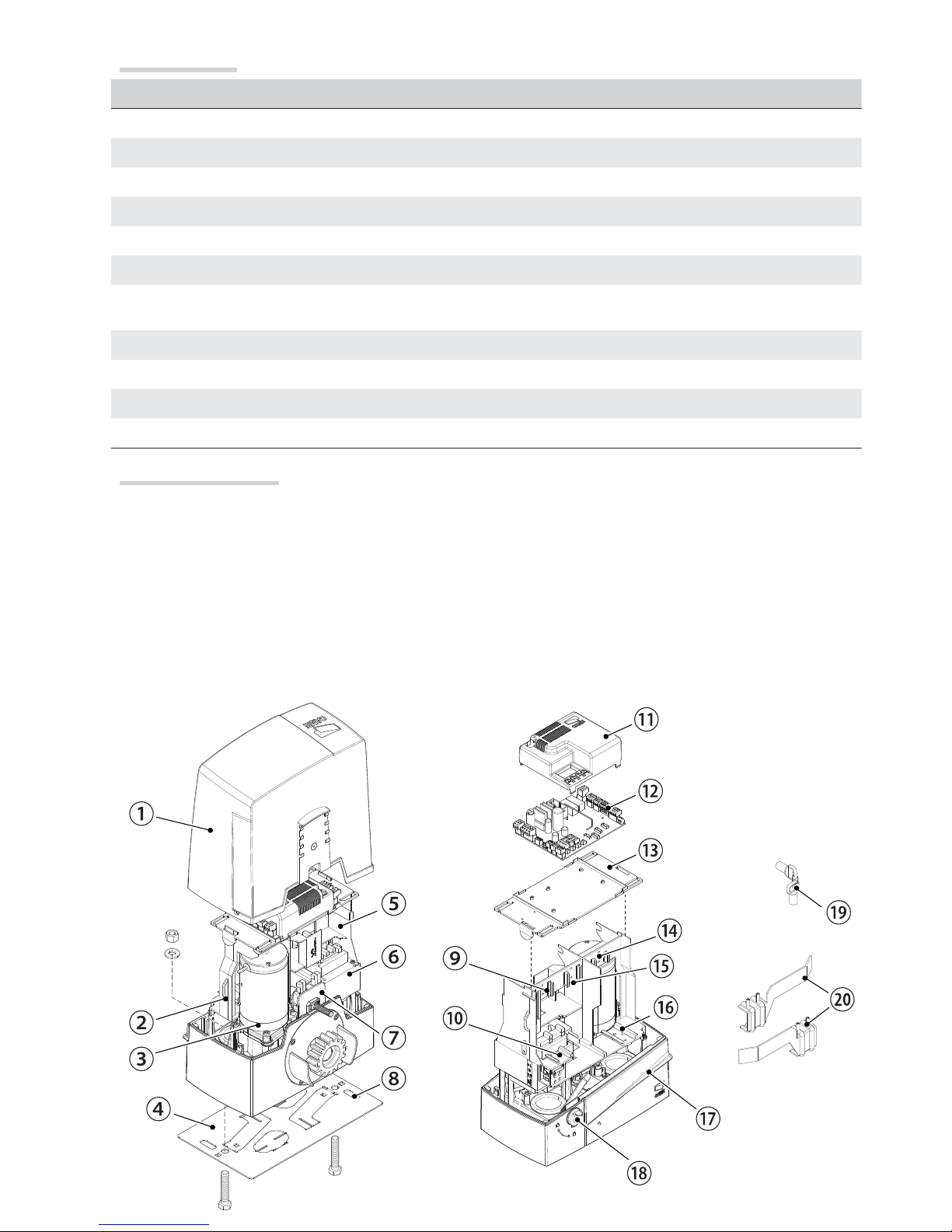
Description of parts
1. Cover
2. Board-fi tting support
3. Gearmotor
4. Anchoring plate
5. Housing for two emergency batteries
6. Transformer
7. Mechanical limit switch
8. Release cable threading hole
9. Housing for the RGP1 module
10. Housing for thermostat with heating rod
11. Protection card lid
12. Control board
13. Control-board holder
14. Housing for the RLB39 battery charger
15. Housing for the GSM module
16. Housing for the SMA sensors
17. Release lever
18. Lock
19. Release key
20. Limit-switch fi ns
Page 6

p.
6
6 - Manual code
FA0 0 0 14 -E N
FA00014-EN v.
3
3 04/2016 - © Came S.p.A. The contents of this manual may be changed at any time without prior notice.
Standard installation
1. Operator
2. Limit-switch fi ns
3. Rack
4. Selector
5. Flashing light
6. Photocells
7. Mechanical gate stop
8. Transmitter
9. Slide guides
10. Junction pit
11. Sensitive safety-edge
GENERAL INSTALLATION INDICATIONS
⚠
Only skilled, qualifi ed sta must install this product.
Preliminary checks
⚠
Before beginning the installation, do the following:
• check that the gate is stable and that the casters are in good working order and lubricated;
• check that the ground rails are well-fastened, entirely on the surface and are smooth and level so as not to
obstruct the gate's movement;
• check that the upper slide-guides are friction-free;
• make sure there is are opening and closing mechanical gate stops;
• make sure that the point where the gearmotor is fastened is protected from any impacts and that the surface is
solid enough;
• make sure you have set up a suitable dual-pole cut o device, along the power supply, that is compliant with the
installation rules. It should completely cut o the power supply according to category III surcharge conditions (that
is, with minimum contact openings of 3 mm);
• make sure that any connections inside the container (ones that ensure continuity to the protection circuit) are
fi tted with additional insulation with respect to those of other electrical parts inside:
• set up suitable tubes and conduits for the electric cables to pass through, making sure they are protected from
any mechanical damage.
Tools and materials
Make sure you have all the tools and materials you will need for installing in total safety and in compliance with
applicable regulations. The fi gure shows some of the equipment installers will need.
Page 7
240
400
300
4
0
p.
7
7 - Manual code
FA0 0 0 14 -E N
FA00014-EN v.
3
3
04/2016 - © Came S.p.A. The contents of this manual may be changed at any time without prior notice.
Cable types and minimum thicknesses
Connection Cable type
Cable length
1 < 10 m
Cable length
10 < 20 m
Cable length
20 < 30 m
Control panel power supply 230 V AC
FROR CEI
20-22
CEI EN
50267-2-1
3G x 1.5 mm
2
3G x 2.5 mm
2
3G x 4 mm
2
Flashing light 2 x 0.5 mm
2
Photocell transmitters 2 x 0.5 mm
2
Photocell receivers 4 x 0.5 mm
2
Command and safety device 2 x 0.5 mm
2
Antenna
the RG58
antenna
max 10 m
Paired connection or CRP UTP CAT5 max 1000 m
If cable lengths di er from those specifi ed in the table, establish the cable sections depending on the actual
power draw of the connected devices and according to the provisions of regulation CEI EN 60204-1.
For multiple, sequential loads along the same line, the dimensions on the table need to be recalculated according
to the actual power draw and distances. For connecting products that are not contemplated in this manual, see the
literature accompanying said products
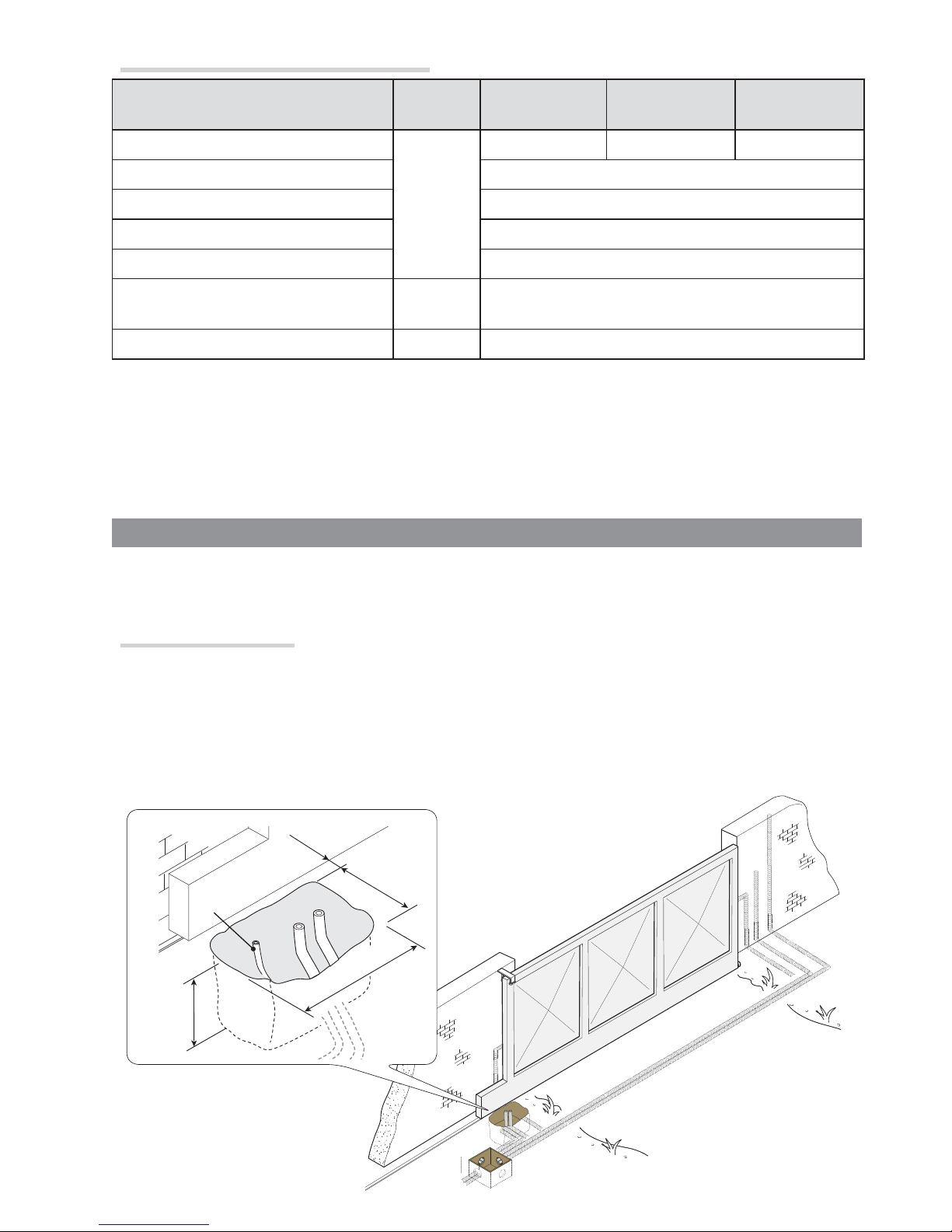
INSTALLATION
⚠
The following illustrations are mere examples. Consider that the space available where to fi t the barrier and
accessories will vary depending on the area where it is installed. It is up to the installer to fi nd the most suitable
solution.
Corrugate tube laying
Dig a hole for the foundation frame.
Set up the corrugated tubes needed for making the connections coming out of the junction pit.
For connecting the gearmotor we suggest using a Ø 40 mm corrugated tube, whereas for the accessories we
suggest Ø 25 mm tubes.
Set up a Ø 20 mm tube for running through the external release cable .
The number of tubes depends on the type of system and the accessories you are going to fi t.
(mm)
Page 8
50
95
106
2
UNI 5734
Ø 12
UNI 5588 M12
p.
8
8 - Manual code
FA0 0 0 14 -E N
FA00014-EN v.
3
3 04/2016 - © Came S.p.A. The contents of this manual may be changed at any time without prior notice.
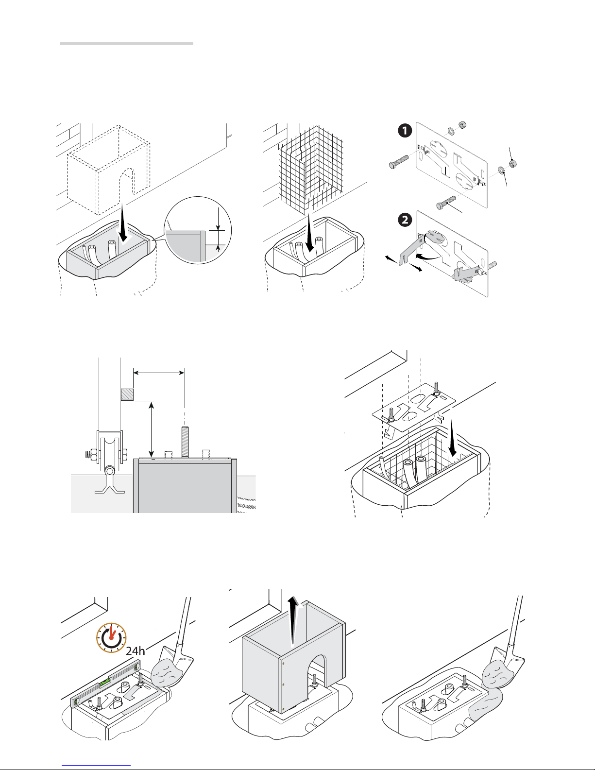
Laying the anchoring plate
Set up a foundation frame that is larger than the anchoring plate and sink it into the dug hole. The foundation frame
must jut out by 50 mm above ground level.
Fit an iron cage into the foundation frame to reinforce the concrete.
Fit the bolts into the anchoring plate and lock them using the washers and nuts. Remove the pre-shaped clamps
using a screw driver or pliers.
If the rack is already there, place the anchoring plate, being careful to respect the measurements shown in the
drawing.
Careful! The tubes must pass through their corresponding holes.
Fill the foundation frame with concrete. The plate must be perfectly level with the bolts which are entirely above
surface.
Wait at least 24 hrs for the concrete to solidify.
Remove the foundation frame and fi ll the hole with earth around the concrete block.
Page 9
5 ÷ 10
p.
9
9 - Manual code
FA0 0 0 14 -E N
FA00014-EN v.
3
3
04/2016 - © Came S.p.A. The contents of this manual may be changed at any time without prior notice.
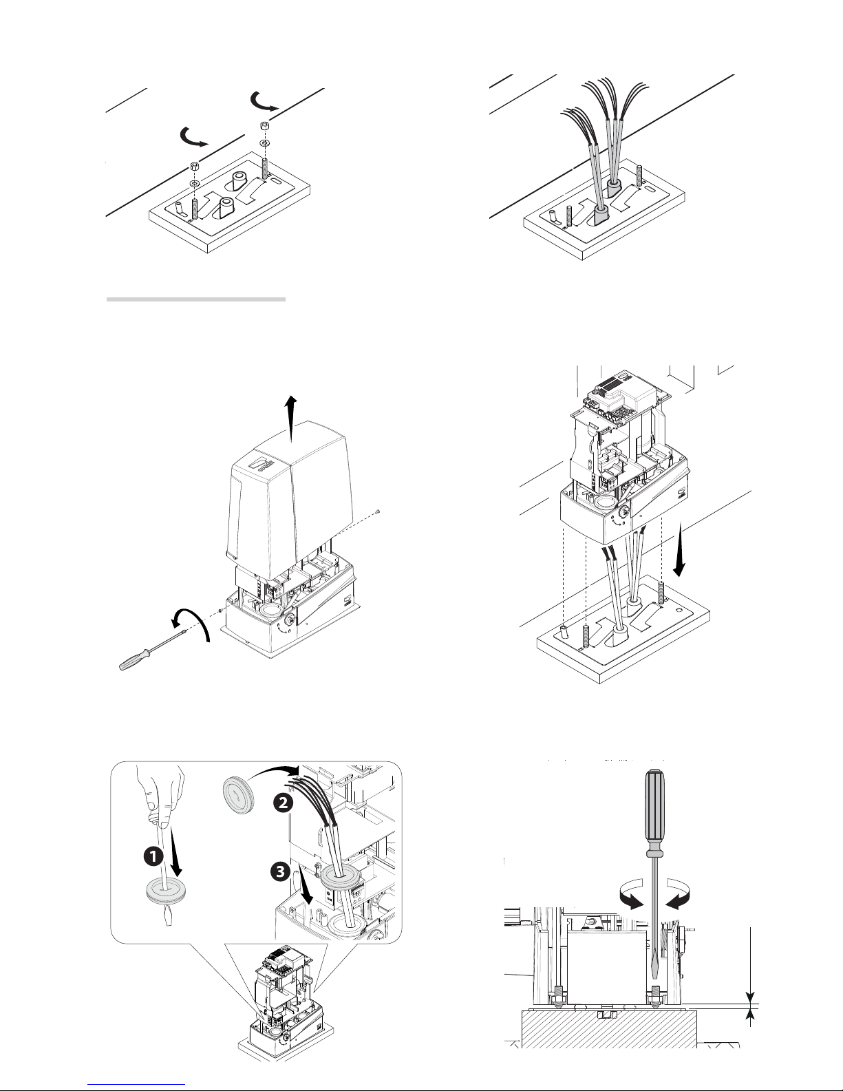
Setting up the gearmotor
Remove the gearmotor cover by loosening the side screws.
Place the gearmotor above the anchoring plate.
Careful! The electric cables must pass under the gearmotor case.
Remove the nut and washer from the bolts
Fit the electric cables into the tubes so that they come out about 600 mm.
Perforate the cable gland, pass the cables through and fi t it into its corresponding housing.
Raise the gearmotor by 5 to 10 mm from the plate by turning the threaded feet, to make room for further pinion
and rack adjustments.
Page 10

1 ÷ 2
p.
10
10 - Manual code
FA0 0 0 14 -E N
FA00014-EN v.
3
3 04/2016 - © Came S.p.A. The contents of this manual may be changed at any time without prior notice.
Fastening the rack
If the rack is already set up, the next step should be to adjust the rack-and-pinion coupling distance, otherwise,
fasten it:
- release the gearmotor (see RELEASING THE GEARMOTOR paragraph);
- rest the rack above the gearmotor pinion;
- weld or fasten the rack to the gate along its entire length.
To assemble the rack modules, use an extra piece and rest it under the joint, then fasten it using two clamps.
Adjusting the pinion-rack coupling
Manually open and close the gate and adjust the pinion-rack coupling distance using the threaded feet (vertical
adjustment) and the holes (horizontal adjustment). This prevents the gate's weight from bearing down on the
operator.
Page 11

~ 20 mm
~ 20 mm
p.
11
11 - Manual code
FA0 0 0 14 -E N
FA00014-EN v.
3
3
04/2016 - © Came S.p.A. The contents of this manual may be changed at any time without prior notice.
Fastening the gearmotor
Complete the adjusting, fasten the gearmotor to the plate using the washers and nuts.
Establishing the limit-switch points
For opening:
- open the gate ;
- fi t the opening limit-switch fi n onto the rack until the micro switch activates (spring) and fasten it using the grub
screws .
For closing:
- close the gate ;
- fi t the closing limit-switch fi n into the rack until the micro-switch is activated (spring) and fasten it using the grub
screws .
Spring
Page 12

p.
12
12 - Manual code
FA0 0 0 14 -E N
FA00014-EN v.
3
3 04/2016 - © Came S.p.A. The contents of this manual may be changed at any time without prior notice.
ELECTRICAL CONNECTIONS AND PROGRAMMING
⚠
Warning! Before working on the control panel, cut o the main current supply and, if present, remove any
batteries.
Power supply to the control board and control devices : 24 V AC/ DC.
Functions on the input and output contacts, time adjustments and user-management settings are set and viewed
on the control board's display.
All connections are quick-fuse protected.
Fuses ZN7
- Line 1.6 A-F
- Accessories 2 A-F
Description of parts
1. Terminal for gearmotors
2. Terminals for encoders
3. Terminals for limit-switches
4. Command and safety devices terminals
5. Antenna terminal
6. AF card connector
7. Memory Roll card connector
8. R700/R800 board connector
9. RSE board connector
10. Connector for the RIO-CONN card
11. Display
12. Programming buttons
13. Terminals for paired of CRP connection
14. Terminals for transponder devices
15. Keypad selector terminal
16. Connector for the GSM module
17. Terminals for the RGP1 module
18. Terminals for signaling devices
19. Accessories fuse
20. Terminals for powering the control board
21. Line fuse
22. Power supply terminal board
Page 13

L
N
M
10 11 E 24 0
M N
+ E -
FC FA F
10 11 E 5
p.
13
13 - Manual code
FA0 0 0 14 -E N
FA00014-EN v.
3
3
04/2016 - © Came S.p.A. The contents of this manual may be changed at any time without prior notice.
Power supply
Signaling devices
24 V DC gearmotor
Green
Brown
White
Factory wiring
Opening limit-switch (NC contact)
Closing limit-switch (NC contact)
230 V AC - 50/60 Hz
24 V AC/DC control board power-supply input
24 V AC/DC - max 40 W accessories power-supply output
Either fl ashing light or cycle light connection output
(Contact rated for: 24 V AC/DC - 25 W max)
See function F 18.
Gate open signaling output
(Contact rated for: 24 V AC/DC - 3 W max)
See function F 10.
Encoder
Orange
White
Red
Orange
Green
Red
Page 14

AF
R700 / R800
R700
R800
AF
CAME
ACCESS CONTROL
A B GND
A B
S1 GND
1 2 3P 7
AF
R700
R800
p.
14
14 - Manual code
FA0 0 0 14 -E N
FA00014-EN v.
3
3 04/2016 - © Came S.p.A. The contents of this manual may be changed at any time without prior notice.
Command and control devices
OPEN or PARTIAL OPENING
function from control device (NO
contact). See function F8.
STOP button (NC contact). For
stopping the gate while excluding
automatic closing. To resume
movement press the control
button or use another control
device. See function F1.
OPEN-CLOSE-INVERT function
(step-step) from control device
(NO contact). Alternatively, from
the functions programming you
can activate the single command
OPEN-STOP-CLOSE-STOP
(sequential). See function F7.
To be able to snap in the cards into the dedicated connectors, remove the card cover.
WARNING! For the system to work properly, before fi tting any plug-in card, such as the AF or R800 one, you MUST
CUT OFF THE MAINS POWER SUPPLY and, if present, disconnect any batteries.
Connector for AF card (AF868 or
AF43S) for remote control.
Keypad selector.
Connector for the R700 card
(for using the transponder
or the card reader) or for
the R800 card (for using the
keypad selector).
Transponder or card reader.
Antenna with cable RG58 for
remote control.
Blue
White
Black
Red
GSM module connector
(for controlling from a
mobile device).
The GSM does
not work if the RGP1
module is connected.
Page 15

TX 2
TX 2
10 2 TX C
-
+
-
NC
FC FA F
10 TS 2 CX CY
1 2 3P 7
DFW
10 TS 2 CX CY
1 2 3P 7
10 TS 2 CX CY
1 2 3P 7
10 11 E 5
DELTA-S DIR
TX 2
+-
+ - NO C-NC
F
C
10 TS 2 CX CY
1 2 3P 7
DELTA
RX
RX
TX
TX
p.
15
15 - Manual code
FA0 0 0 14 -E N
FA00014-EN v.
3
3
04/2016 - © Came S.p.A. The contents of this manual may be changed at any time without prior notice.
DFW with control board of the
DFI connections
Sensitive Safety Edges
Confi gure contact CX or CY (NC), input for safety devices such as sensitive safety-edges, that are EN 12978
regulation compliant.
See CX input functions (Function F2) or CY (Function F3) in:
- C7 reopening during closing. when the gate is closing, opening the contact causes the inversion of movement
until opening is complete;
- C8 reclosing during opening. When the gate is opening, opening the contact triggers the inversion of movement
until the gate is fully closed.
If contacts CX and CY are not used they should be deactivated during programming.
Safety devices
Photocells
Confi gure contact CX or CY (NC), input for safety devices such as photocells, which comply with EN 12978
regulations.
See CX input functions (Function F2) or CY (Function F3) in:
- C1 reopening during closing. when the gate is closing, opening the contact causes the inversion of movement
until opening is complete;
- C2 close back up during opening. When the gate is opening, opening the contact triggers the inversion of
movement until the gate is completely closed.
- C3 partial stop. Stopping of the gate, if it is moving, with consequent automatic closing (if the automatic closing
function has been entered);
- C4 obstacle wait. Stopping of the gate, if it is moving, which resumes movement once the obstruction is removed.
If contacts CX and CY are not used they should be deactivated during programming.
Page 16

A B GND
UTP CAT 5
A B GND
1 2 3 4
1
2
3
4
RSE
RSE
TX 2
TX 2
10 2 TX C
+
-
NC
FC FA F
10 TS 2 CX CY
1 2 3P 7
-
+
-
DELTA-S DIR
F
C
10 TS 2 CX CY
1 2 3P 7
TX 2
+-
+ - NO C NC
DELTA
RIO-CONN
RIO-CONN
RIO-CELLRIO-EDGE RIO-LUX
RX TX RX TX
p.
16
16 - Manual code
FA0 0 0 14 -E N
FA00014-EN v.
3
3 04/2016 - © Came S.p.A. The contents of this manual may be changed at any time without prior notice.
Connecting the safety devices (i.e. the safety test)
At each opening and closing command, the control board checks the e cacy of the safety devices (such as,
photocells).
Any malfunction inhibits any command and is signaled on display E4.
Enable function F5 in programming.
See the PAIRED CONNECTION WITH
SINGLE CONTROL chapter.
Connection for paired operation and for CRP (Came Remote Protocol)
Fit the RSE card.
Rio Wireless devices
Fit the RIO-CONN card into the corresponding connector on the control board.
Set the function to be associated to the wireless device (F65, F66, F67 e F68).
Confi gure the RIO-EDGE, RIO-CELL and RIO-LUX wireless devices by following the indications shown in the folder
enclosed with each accessory.
If the devices are not confi gured with the RIO-CONN card, the E18 error message appears on the display.
⚠
If there are any radio-frequency disturbances to the system, the wireless system will inhibit the normal operation
of the operator, and this error will show up on the display as E17.
Page 17

888
F
i
F
i
F
2
F
3
0
i
03
i3
p.
17
17 - Manual code
FA0 0 0 14 -E N
FA00014-EN v.
3
3
04/2016 - © Came S.p.A. The contents of this manual may be changed at any time without prior notice.
The ENTER key is for:
- entering menus;
- confi rming or memorizing set values.
The ESC button is for:
- exiting menus;
- cancelling changes.
The < > keys are for:
- moving from one item to another;
- increasing or decreasing values.
Display
To enter the menu, keep the
ENTER button pressed for at
least one second.
To select menu items, use
the arrow keys ...
... then press ENTER
also for the submenus, use
the arrow keys to select ...
To increase or decrease a
value, use the arrow keys ...
... to exit the menu, wait 10
seconds or press ESC.
When the menu is active, the system cannot be used.
... the press ENTER to
confi rm ...
... then press ENTER
Description of programming commands
Browsing the menu
Page 18

p.
18
18 - Manual code
FA0 0 0 14 -E N
FA00014-EN v.
3
3 04/2016 - © Came S.p.A. The contents of this manual may be changed at any time without prior notice.
Functions map
F 1 Total stop function (1-2)
F 2 Function associated to input 2-CX
F 3 Function associated to input 2-CY
F 5 Safety test function
F 6 Maintained action function
F 7 Control mode on 2-7
F 8 Control mode on 2-3P
F 9 Obstruction detection with motor idle function
F 10 Function associated to the gate-open signaling output
F 11 Encoder exclusion
F 12 Slowed-down start function
F 14 Sensor type selection function
F 18 Additional light function
F 19 Automatic closing time
F 20 Automatic closing time after partial opening
F 21 Prefl ashing time
F 28 Adjusting opening speed
F 30 Adjusting opening slow-down speed
F 34 Sensitivity during movement
F 35 Sensitivity during slow-down
F 36 Adjusting partial opening
F 37 Adjusting the gearmotor's opening slow-down starting point
F 38 Adjusting the gearmotor's closing slow-down starting point
F 49 Managing the serial connection
F 50 Saving data in memory roll
F 51 Reading memory roll data
F 52 Transferring parameters from Master to Slave
F 54 Opening direction
F 56 Peripheral number
F 63 Changing COM speed
F 65 Function associated to the RIO-EDGE [T1] input
F 66 Function associated to the RIO-EDGE [T2] input
F 67 Function associated to the RIO-CELL [T1] input
F 68 Function associated to the RIO-CELL [T2] input
F 71 Partial opening time
U 1 Entering new user with an associated command
U 2 Deleting single users
U 3 Deleting all users
A 1 Motor-type setting
A 3 Calibrating travel
A 4 Resetting parameters
A 5 Counting maneuvers
H 1 Software version
Page 19

p.
19
19 - Manual code
FA0 0 0 14 -E N
FA00014-EN v.
3
3
04/2016 - © Came S.p.A. The contents of this manual may be changed at any time without prior notice.
F1 Total stop [1-2] 0 = Deactivated (default) / 1 = Activated
NC input – Gate stop that excludes any automatic closing; to resume movement, use the control device. The
safety device is inserted into [1-2].
F2 Input [2-CX]
0 = Deactivated (default) / 1 = C1 / 2 = C2 / 3 = C3 / 4 = C4 / 7 = C7
/ 8 = C8
NC input – Can associate: C1 = reopening during closing by photocells, C2 = reclosing during opening by
photocells, C3 = partial stop, C4 = obstruction wait, C7 = reopening during closing by sensitive safety-edges,
C8 = reclosing during opening by sensitive safety-edges.
F3 Input [2-CY]
0 = Deactivated (default) / 1 = C1 / 2 = C2 / 3 = C3 / 4 = C4 / 7 = C7
/ 8 = C8
NC input – Can associate: C1 = reopening during closing by photocells, C2 = reclosing during opening by
photocells, C3 = partial stop, C4 = obstruction wait, C7 = reopening during closing by sensitive safety-edges,
C8 = reclosing during opening by sensitive safety-edges.
F5 Safety test 0 = Deactivated (default) / 1 = CX / 2 = CY / 4 = CX+CY
After every opening or closing command, the board will check whether the photocells are working properly.
The safety test is always active for wireless devices.
F6 Maintained action 0 = Deactivated (default) / 1 = Activated
The gate opens and closes by keeping the button pressed. Opening button on contact 2-3P and closing button
on contact 2-7. All other control devices, even radio-based ones, are excluded.
F7 Command [2-7] 0 = Step-step (default) / 1 = Sequential
From the control device connected to 2-7 it performs the step-step (open-close-invert) or sequential (open-stopclose-stop) command.
F8 Command [2-3P] 0 = Opening (default) / 1 = Partial opening
From the control device connected to 2-3P it performs the total opening (0) or partial opening (1) of the gate.
The partial opening time is adjusted on function F 71.
F9 Obstruction detection with
motor idle
0 = Deactivated (default) / 1 = Activated
With the gate closed, opened or totally stopped, the gearmotor stays idle if the safety devices, that is, photocells
or sensitive safety-edges detect an obstruction.
F10 Gate-.open signal output 0 = lit when gate is open or moving (default) /
1 = when opening it fl ashes intermittently every half-second,
when closing it fl ashes intermittently every second,
stays lit when gate is open
is o when gate is closed
It signals the gate status. The signal device is connected to contact 10-5.
F11 Encoder 0 = Activated (default) / 1 = Deactivated
Functions menu
IMPORTANT! Start programming by fi rst performing the following: MOTOR-TYPE SETTING (A1), OPENING
DIRECTION (F54), TOTAL STOP (F1) and TRAVEL CALIBRATION (A3)
⚠
Programming the features is to be done when the operator is stopped.
You can memorize up to 25 users.
Page 20

p.
20
20 - Manual code
FA0 0 0 14 -E N
FA00014-EN v.
3
3 04/2016 - © Came S.p.A. The contents of this manual may be changed at any time without prior notice.
Managing slow-downs, obstruction detections and sensitivity.
F12 Slowed-down departure 0 = Deactivated (default) / 1 = Activated
With each opening and closing command, the gate starts moving slowly for a few seconds.
F14 Sensor type selection 0 = command with transponder sensor or magnetic card reader /
1 = command with keypad selector (default).
Setting the type of accessory for controlling the operator.
F18 Additional light 0 = Flashing light (default) / 1 = Cycle
Output on contact 10-E.
Flashing light: it fl ashes during the gate's opening and closing phases.
Cycle: external light for increased lighting of the driveway, it stays lit from the beginning of the opening until
complete closing, including the waiting time before the automatic closing.
F19 Automatic closing time 0 = Deactivated (default) / 1 = 1 second / ... / 180 = 180 seconds
The automatic-closing wait starts when the opening limit switch point is reached and can be set to between 1
and 180 seconds. The automatic closing does not turn on if any of the safety devices trigger when an obstruction
is detected, after a total stop or during a power outage.
F20 Automatic closing time
after a partial opening
0 = Deactivated / 1 = 1 second / … / 10 = seconds (default) / … / 180
= 180 seconds
The wait before the automatic closing starts after a partial opening command for an adjustable time of between
1 s and 180 s.
The automatic closing does not turn on if any of the safety devices trigger when an obstruction is detected, after
a total stop or during a power outage.
The F19 function must not be activated.
F21 Prefl ashing time 0 = Deactivated (default) / 1 = 1 second / … / 10 = 10 seconds
Adjusting the pre-fl ashing time for the fl ashing light connected to 10-E before each maneuver. The fl ashing time
is adjustable from 1 to 10 seconds.
F28 Travel speed 60 = Minimum speed / … / 100 = Maximum speed (default)
Setting the gate's opening and closing speeds, calculated as a percentage.
F30 Slow-down speed 10 = Minimum speed / … / 50 = Maximum speed (default)
Setting the gate's opening and closing slow-down speed, calculated as a percentage.
F34 Boom travel sensitivity 10 = maximum sensitivity / … / 100 = minimum sensitivity (default)
Adjusting obstruction detection sensitivity during boom travel.
F35 Slow-down sensitivity 10 = maximum sensitivity / … / 100 = minimum sensitivity (default)
Adjusting obstruction detection sensitivity during slow-down.
F36 Adjusting partial opening 10 = 10% of the travel( default ) / … / 80 = 80% of the travel
Adjustment as a percentage of total travel, during gate opening.
This function appears only is the Encoder function is activated.
Page 21

p.
21
21 - Manual code
FA0 0 0 14 -E N
FA00014-EN v.
3
3
04/2016 - © Came S.p.A. The contents of this manual may be changed at any time without prior notice.
F37 Opening slow-down point 10 = 10% of the travel / … / 25 = 25% of the travel (default) / … / 60
= 60% of the travel
Percentage adjustment of the total gate travel, of the opening slow-down starting point.
This function appears only is the Encoder function is activated.
F38 Closing slow-down point 10 = 10% of the travel / … / 25 = 25% of the travel (default) / … / 60
= 60% of the travel
Percentage adjustment of the total gate travel, from the closing slow-down starting point.
This function appears only is the Encoder function is activated.
F49 Manage serial connection 0 = Deactivated (default) / 1 = Paired / 3 = CRP
To enable paired operation or the Came Remote Protocol.
F50 Save data 0 = Deactivated (default) / 1 = Activated
Saving users and saved settings in memory roll.
This feature only appears if a memory roll has been fi tted into the control board.
F51 Read data 0 = Deactivated (default) / 1 = Activated
Uploading data saved in memory roll.
This feature only appears if a memory roll has been fi tted into the control board.
F52 Passing parameter in
paired mode
0 = Deactivated (default) / 1 = Activated
Uploading settings from Master to Slave.
This appears only if function F49 is set to Paired.
F54 Opening direction 0 = Opening towards the left (default) / 1 = Opening towards the right
For setting the gate opening direction.
F56 Peripheral number 1 ----> 255
To set the peripheral's number from 1 to 255 for each control board when you have a system with several
operators.
F63 Change COM speed 0 = 1200 Baud / 1 = 2400 Baud / 2 = 4800 Baud / 3 = 9600 Baud / 4
= 14400 Baud / 5 = 19200 Baud / 6 = 38400 Baud / 7 = 57600 Baud /
8 = 115200 Baud
For setting the communication speed used in the CRP (Came Remote Protocol) connection system.
F65 RIO-EDGE [T1] wireless
input
0 = Deactivated (default) / 7 = P7 / 8 = P8
RIO-EDGE wireless safety device associated to any function chosen among those available: P7 = reopening
during closing, P8 = reclosing during opening.
For programming, see the instructions that come with the accessory.
This function only appears is the control board has been fi tted with a RIO-CONN card.
F66 RIO-EDGE [T2] wireless
function
0 = Deactivated (default) / 7 = P7 / 8 = P8
RIO-EDGE wireless safety device associated to any function chosen among those available: P7 = reopening
during closing, P8 = reclosing during opening.
For programming, see the instructions that come with the accessory.
This function only appears is the control board has been fi tted with a RIO-CONN card.
Page 22

p.
22
22 - Manual code
FA0 0 0 14 -E N
FA00014-EN v.
3
3 04/2016 - © Came S.p.A. The contents of this manual may be changed at any time without prior notice.
F67 RIO-CELL [T1] wireless
input
0 = Deactivated / 1 = P1 (default) / 2 = P2 / 3 = P3 / 4 = P4
RIO-CELL is associated to any function chosen among those available: P1 = reopening during closing; P2 =
reclosing during opening; P3 = partial stop; P4 = obstruction wait.
For programming, see the instructions that come with the accessory.
This function only appears is the control board has been fi tted with a RIO-CONN card.
F68 RIO-CELL [T2] wireless
input
0 = Deactivated / 1 = P1 (default) / 2 = P2 / 3 = P3 / 4 = P4
RIO-CELL is associated to any function chosen among those available: P1 = reopening during closing; P2 =
reclosing during opening; P3 = partial stop; P4 = obstruction wait.
For programming, see the instructions that come with the accessory.
This function only appears is the control board has been fi tted with a RIO-CONN card.
F71 Partial opening time 5 = 5 seconds /....... / 40 = 40 seconds
After an opening command from the button connected to 2-3P, the gate opens for an adjustable time of between
5 seconds and 40 seconds.
This function only appears if the Encoder function is deactivated.
U 1 Entering a user 1 = Step-step command (open-close) / 2 = Sequential command (open-
stop-close-stop) / 3 = Only open command / 4 = Partial command
Entering up to up to a 25 users maximum and associating to each one a function chosen among the existing
ones. This must be done via transmitter or other control device (see "ENTERING USERS WITH ASSOCIATED
COMMAND paragraph).
U 2 Deleting a user
Deleting a single user
U 3 Deleting users 0 = Deactivated / 1 = Deleting all users
Deleting all users.
A 1 Motor type 1 = 400 Kg / 2 = 600 Kg / 3 = 800 Kg / 4 = 1000 Kg
To set the gearmotor depending on the gate's weight.
A 3 Calibrating boom travel 0 = Disable / 1 = Activate
Automatic calibration of the gate-leaf run (see the CALIBRATING GATE-LEAF RUN paragraph).
A 4 Resetting parameters 0 = Disable / 1 = Activate
Warning! The default settings are restored and the travel calibration deleted.
A 5 Counting maneuvers 0 = Number of maneuvers made / 1 = Deleting all maneuvers
For viewing the number of maneuvers completed or for deleting them (001 = 100 maneuvers; 010 = 1,000
maneuvers; 100 = 10,000 maneuvers; 999 = 99,900 maneuvers; CSI = maintenance job).
H 1 Version
View the fi rmware version.
Page 23

2 5
iU
2
2U
2 2
C l
p.
23
23 - Manual code
FA0 0 0 14 -E N
FA00014-EN v.
3
3
04/2016 - © Came S.p.A. The contents of this manual may be changed at any time without prior notice.
Select U 1
Press ENTER to confi rm.
... a number from 1 to 25 will fl ash for a few
seconds
Send the code from the transmitter or other
control device, such as, a keypad selector or a
transponder.
Associate the number to the entered user.
Select a command to associate to the user.
The commands are:
- step-step (open-close) = 1;
- sequential (open-stop-close-stop) = 2;
- open = 3;
- partial opening = 4.
Press ENTER to confi rm...
User Associated command
1 -
2 -
3 -
4 -
5 -
6 -
7 -
8 -
9 -
10 -
11 -
12 -
13 -
14 -
15 -
16 -
17 -
18 -
19 -
20 -
21 -
22 -
23 -
24 -
25 -
Entering a user with an associated command
When entering/deleting users, the fl ashing numbers that appear, are numbers that can be used for other users
you may wish to enter (maximum 25 users).
Select U 2.
Press ENTER to confi rm.
Use the arrow keys select the number of the user
you wish to delete.
Press ENTER to confi rm...
... Clr will appear on the screen to confi rm
deletion.
Deleting a single user
Page 24

3a
i
C l i
O P i
p.
24
24 - Manual code
FA0 0 0 14 -E N
FA00014-EN v.
3
3 04/2016 - © Came S.p.A. The contents of this manual may be changed at any time without prior notice.
Select A 3.
Press ENTER to confi rm.
Select 1 and press ENTER to confi rm the
travel calibration operation.
The gate will perform a closing maneuver
until it reaches a fi nal stop...
...then the gate will perform an opening
maneuver until it reaches a fi nal stop.
Travel calibration
Before calibrating the gate travel, position the gate half-way, check that the maneuvering area is clear of any
obstruction and check that there are mechanical opening and closing stops.
⚠
The mechanical end-stops are obligatory.
Important! During the calibration, all safety devices will be disabled except for the PARTIAL STOP one.
Memory Roll Card
To memorize user data and confi gure the system, to then reuse them with another control board even on another
system.
After memorizing the data, it is best to remove the Memory Roll.
Memory Roll.
Page 25

MASTER SLAVE
MASTER SLAVE
p.
25
25 - Manual code
FA0 0 0 14 -E N
FA00014-EN v.
3
3
04/2016 - © Came S.p.A. The contents of this manual may be changed at any time without prior notice.
PAIRED CONNECTION
Important! Start by performing the following procedures on both operators:
- fi t the RSE card (with the DIP-switches set to OFF) on the connector of both operator's cards.
- connect the two cards using a CAT 5 (max 1,000 m) cable on terminals A-A / B-B / GND-GND, see the PAIRED
CONNECTION paragraph.
- connect all of the control and safety devices on the MASTER operator's control panel.
Important! Deactivate function F19 (automatic closing time) on the SLAVE operator's control panel.
Confi guring the MASTER operator
Select function F 49. Press ENTER to confi rm.
Select 1 (paired) and press ENTER.
Perform settings and adjustments on the control board.
Transferring parameters from MASTER to SLAVE
Select function F 52 on the MASTER control panel.
Select 1 and press ENTER.
Programming
On both operators, set the following functions:
- the type of motor (A1);
- the opening direction (F54);
- total stop (F1);
- travel calibration (A3).
Proceed with the settings and adjustments on the MASTER control board.
Operating modes
Either STEP-STEP or ONLY OPEN command. Both leaves open.
PARTIAL/PEDESTRIAN OPENING command. Only the MASTER operator's leaf opens.
For the types of command that can be selected and paired to users, see the ENTERING USERS WITH ASSOCIATED
COMMANDS.
Page 26

p.
26
26 - Manual code
FA0 0 0 14 -E N
FA00014-EN v.
3
3 04/2016 - © Came S.p.A. The contents of this manual may be changed at any time without prior notice.
RELEASE
FINAL OPERATIONS
Once the electrical connections are done and the set up is fi nished, fasten the cables to the gearmotor jumper
using a cable tie.
Fit the cover and fasten it to the sides using the screws.
RELEASING THE GEARMOTOR
⚠
This procedure must be done with the main power cut o .
⚠
Manually releasing the operator may result in uncontrolled movement of the gate, if this has any mechanical
problems or is unbalanced.
LOCK
Page 27

p.
27
27 - Manual code
FA0 0 0 14 -E N
FA00014-EN v.
3
3
04/2016 - © Came S.p.A. The contents of this manual may be changed at any time without prior notice.
Date Notes Signature
MAINTENANCE
TROUBLES
POSSIBLE CAUSES FIXES
It neither opens nor
closes
• Power supply is missing
• The gearmotor is stuck
• The transmitter doesn't work
• The transmitter is broken
• The stop button is either stuck or broken
• The opening/closing button or the key-switch
selector is stuck
• The wireless accessory does not work
• Check main power supply
• Lock the gearmotor
• Replace the batteries
• Call for assistance
• Call for assistance
• Call for assistance
• Call for assistance
The gate opens but
does not close
• The photocells are dirty • Clean and check proper
functioning of the photocells
TROUBLESHOOTINGMAINTENANCE
Periodic maintenance
☞ Before any maintenance job, cut o the mains power supply, to prevent hazardous situations due to accidental
movement of the operator.
Periodic maintenance log to be fi lled in by users every six months.
ERROR MESSAGE
The error messages are shown on the display.
E 1 The travel calibration was interrupted when the STOP button was activated
E 2 Calibrating the complete gate-travel
E 3 Encoder broken
E 4 Services test error
E 7 Insu cient working time
E 8 The NC contacts are open (for example, the limit-switches)
E 9 Closing obstruction
E 10 Opening obstruction
E 11 Maximum number of detected obstructions
E 14 Serial communication error
E 17 Wireless system error
E 18 The wireless system confi guration is missing
Page 28

www. came.com
www. came.com
CAME S.p.A.
CAME S.p.A.
Via Martiri Della Libertà, 15 Via Cornia, 1/b - 1/c
31030
Dosson di Casier
Dosson di Casier
Treviso
Treviso - Italy
33079
Sesto al Reghena
Sesto al Reghena
Pordenone
Pordenone - Italy
(+39) 0422 4940
(+39) 0422 4941
(+39) 0434 698111
(+39) 0434 698434
Eng l i s h
English - Manual code
FA0 0 0 14 -E N
FA00014-EN v.
3
3 04/2016 - © Came S.p.A .
The data and information in this manual are susceptible to changes at any time and without prior notice
Extraordinary maintenance
The following table is for logging any extraordinary maintenance jobs, repairs and improvements performed by
specialized contractors.
Any extraordinary maintenance jobs must be done only by specialized technicians.
Extraordinary maintenance log
Fitter's stamp Name of operator
Job performed on (date)
Technician's signature
Requester's signature
Job performed
___________________________________________________________________________
______________________________________________________________________________________
______________________________________________________________________________
DISMANTLING AND DISPOSAL
☞
CAME S.p.A. applies a certifi ed Environmental Management System at its premises, which is compliant with the UNI EN
ISO 14001 standard to ensure the environment is safeguarded.
Please continue safeguarding the environment. At CAME we consider it one of the fundamentals of our operating and
market strategies. Simply follow these brief disposal guidelines:
DISPOSING OF THE PACKAGING
The packaging materials (cardboard, plastic, and so on) should be disposed of as solid urban waste, and simply separated
from other waste for recycling.
Always make sure you comply with local laws before dismantling and disposing of the product.
DO NOT DISPOSE OF IN NATURE!
DISMANTLING AND DISPOSAL
Our products are made of various materials. Most of these (aluminum, plastic, iron, electrical cables) is classifi ed as solid
household waste. They can be recycled by separating them before dumping at authorized city plants.
Whereas other components (control boards, batteries, transmitters, and so on) may contain hazardous pollutants.
These must therefore be disposed of by authorized, certifi ed professional services.
Before disposing, it is always advisable to check with the specifi c laws that apply in your area.
DO NOT DISPOSE OF IN NATURE!
DECLARATION OF CONFORMITY
Declaration - Came S.p.A. declares that this device conforms to the essential, pertinent requirements provided by
directives 2006/42/CE, 2006/95/CE and 2004/108/CE.
An original copy of the declaration of conformity is available on request.
 Loading...