

Page 1
CANCELLI AUTOMATICI
AUT OMATION SYSTEM FOR SLIDING DOORS,
SERIES
R ODEO
AUTOMATION SYSTEM FOR SLIDING DOORS
WITH MICROPROCESSOR CONTR OL
Documentazione
Tecnica
M71
rev. 3.4
08/2005
©
CAME
CANCELLI
AUTOMATICI
119PM71
T
I
X
E
Y
R
T
N
E
Y
C
N
E
G
R
E
M
E
D
E
S
O
L
C
N
O
I
T
C
E
L
E
S
for door wings weighting
up to
# kg each
Page 2
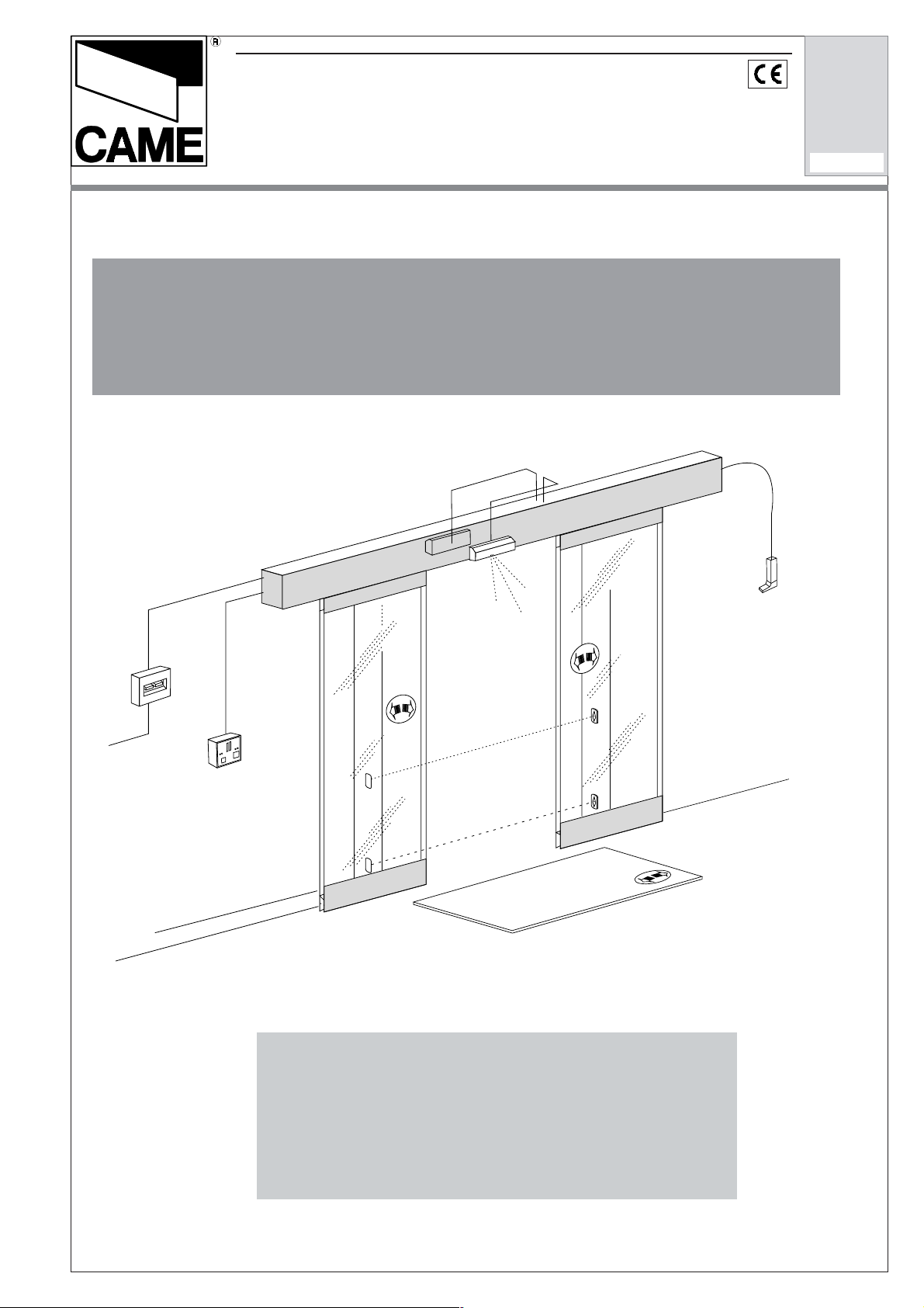
SERIE RODEO
GENERAL CHARACTERISTICS
Description:
System for sliding doors automatic
opening.
Designed and built entirely by CAME
CANCELLI AUTOMATICI S.p.A. with
IP40 protection level. 12-month
warranty subject to tampering.
- CORSA 1, reversible 24V gear motor
with integrated circuit board.
Automation for single-door entrances
up to 3,300 mm with weight max. 125
Kg.
- CORSA 2, reversible 24V gear motor
with integrated circuit board.
Automation for entrances with 2 door
up to 3,300 mm with weight max. 125
Kg per door.
Models:
- MA7012 Electric lock;
- MA7032 Battery-powered anti-panic
system;
- MA7041 Function selector;
- MS9502 Touch-activated switch;
- MF9011/9111 Command and safety
photocells;
- MR8001/8002 Infrared radar;
- MR8104/8105 Microwave radar;
- MR8334-70-90 Activ infrared safety
sensor;
- MP8030/8060 Pressure-sensitive;
- MRT001 remote control for MR8104
e MR8105.
For easy installation and maintenance, be sure to use CAME original control equipment, safety systems and accessories.
SNOITACIFICEPSLACINHCET
EGATLOV YCNEUQERF
.c.aV032
.c.aV42
zH06/05A6
XAMROTOM
TNERRUC
1
LANIMON
TNERRUC
)V032(
A6,0
W09noitamotuA
W02seirosseccA
NOITPMUSNOCREWOP ELCYCYTUD
2
EVIRD
METSYS
M8DTH
dehtoot
tleb
Optional accessories:
.XAM
ECROF
DETREXE
gK8
DEEPSGNINEPO
1oedoRs/mc54
2oedoRs/mc08
GNITAREPO
ERUTAREPMET
°07+<°02-
(1) Upon request, there is the possibility of powering up the automation with a different voltage
(2) Heavy-duty-service
DIMENSIONS
(1)
The basic dimensions necessary for building a CAME automation system
for automatic entrance control are door wing width A (or the total width of the
The following pages contain a provisional
diagram
series. Although the dim
installation procedures for the RODEO
series are indicated on the diagram
two door wings) and the overall length T of the beam which contains the
automation mechanism. The relationship between these two dimensions is as
follows: T = A x 2 + 20 mm
AUTOMATION SYSTEM FOR
ENTRANCES WITH 2 DOOR WINGS
M
(1)
A
TTENTION
!
When our series 20 and series 40 profiles are used to
construct the door wings, different dimensions from
those indicated above may result. See the printed
information supplied with the profiles.
AUTOMATION SYSTEM FOR
ENTRANCES WITH 1 DOOR WING**
** When placing the order, be
sure to specify the direction in
which door opens (see the order
form).
ssVp
!!
!
!!
PORTANT
PORTANT
PORTANT
PORTANT
PORTANT
IM
IM
IM
IM
IM
of the trolley for the CORSA
ensions and
, all
references to RODEO and the ZP8
electrical cabinet also apply to CORSA
and the ZP7 electrical cabinet.
M
ssVp
A
T
BASIC DIMENSIONS
T = Total length of beam
A = Total width of door wings, complete with weather stripping
2
A
T
OTHER DIMENSIONS
Vp= Passage area
s = Overlap between moving door wing(s) and
fixed parts (walls and/or non-moving door wings)
Page 3
SECTION-COVERING BOXES DIMENSIONS
SERIE RODEO
Drilling for fixing the section
A
T = Length of the beam
30±0,5
151
85±0,513±6
250250250250
Sez. A-A
126
250 x
n°
step
20
70
Right side/internal view
point of departure
of the step drilling
BEAM WITH
SECTION-
COVERING BOX
SERIES 001LC00
169
AND LTC
STOPPERS
=
151
A
29±6
135
18
69
BEAM WITH
SECTION-
COVERING BOX
30±0,5
SERIES 001LD00
AND LTD
STOPPERS
24
+
1
2
A
195
85±0,5
44
13±6
75
29±6
The section-covering
system Series
001LD00 has LTD
side plugs in ABS
and brackets that
allow the sectioncovering to be
supported in
opening position.
73
Respect the sectioncovering opening
measurements and
measurement (A) for
releasing the section
in maximum-opening
position, 2 cm
approximately.
300
3
Page 4
SERIE RODEO
DIAGRAMS OF GLASS DOOR WINGS
Y = height at which beam is
mounted
= H + 18 mm
13±6
SUPPORT PROFILE
H = working height of passage
V = height of glass door
40
18
17
ATTACH SECTION
CRYSTAL
70
53
29±6
Y
INNER GUIDE
H
CAPS FOR
CENTERING
GLASS
ROLLER
SOLUTION FOR GLASS
WING WHIT
DOOR
LOWER
V
DOOR
WING
10
SKIRT
LOWER
PROFILE
/GUIDE
80
1622
SOLUTION FOR GLASS
WING WITHOUT
DOOR
LOWER
SKIRT
20
10
16
3417.5
V
ø 4.8
2021.5
10
OUTER
GUIDE
ROLLER
V =
H - 70 mm
Y - 88 mm
4
V =
H - 22 mm
Y - 40 mm
Page 5
DIAGRAMS OF GLASS DOOR WINGS
GLASS DOOR WING(S) WITH
LOWER SKIRT
L
SERIE RODEO
MA 7370 = L 1000 mm
MA 7470 = L 1500 mm
MA 7570 = L 2000 mm
L
MA 7353 = L 1000 mm
MA 7453 = L 1500 mm
MA 7553 = L 2000 mm
DRILL POINTS FOR INSTALLING THE UPPER GLASS PANEL AND BEAMBEAM
L wing
101
101
Profile
ø 8.5
100
18
min. 300
32
ø 16
100
Glass (max 10 mm)
L wing - 2 mm
GLASS DOOR WING(S) WITHOUT
LOWER SKIRT
L
MA 7370 = L 1000 mm
MA 7470 = L 1500 mm
MA 7570 = L 2000 mm
L
5
Page 6
SERIE RODEO
DIAGRAMS OF DOOR WINGS WITH FRAME
Y = height at which beam is
H = working height of passage
I = height of door wing with frame
7
4
13±6
ATTACH SECTION
FRAMED
10 8 4
mounted
= H + 18 mm
18 11
26.5
4.5
29±6
SOLUTION FOR
DOOR WING
I
10
FRAMED
WITH
PROFILE
INSTALLED
EXTERNALLY
BOTTOM
/GUIDE
30
SOLUTION FOR
DOOR WING
FRAMED
WITHOUT
Y
H
I
PROFILE
BOTTOM
/GUIDE
10
40
FRAMED
I
10
SOLUTION
DOOR WING
BOTTOM
WITH
PROFILE
/GUIDE
INSTALLED
INTERNALLY
FOR
OUTER GUIDE
6
ROLLER
I =
H - 28 mm
Y - 46 mm
INNER GUIDE
ROLLER
20
H - 48 mm
Y - 66 mm
20
I =
I =
H - 28 mm
Y - 46 mm
LOWER
PROFILE
/GUIDE
2
Page 7
DIAGRAMS OF DOOR WINGS WITH FRAME
DOOR WING(S) WITH
FRAME, WITHOUT LOWER
GUIDE PROFILE
L
L
SERIE RODEO
MA 7371= L 1000 mm
MA 7471= L 1500 mm
MA 7571= L 2000 mm
MA 7371= L 1000 mm
MA 7471= L 1500 mm
MA 7571= L 2000 mm
DOOR WING(S) WITH
FRAME, WITH LOWER
GUIDE PROFILE
MA 7351 = L 1000 mm
MA 7451 = L 1500 mm
MA 7551 = L 2000 mm
7
Page 8
SERIE RODEO
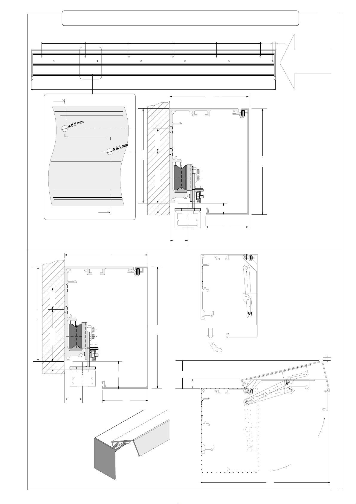
INSTALLING THE BEAM
1) Remove the profile housing (optional at extra cost), if present
2) Remove the trolleys from the support profile by proceeding as follows:
2 a) Loosen the mounting
screws to disconnect the
trolleys (which are engaged by
the belt) from the connecting
bracket;
TROLLEY WITH LOWER
ATTACHMENT SYSTEM
FOR BELT
TROLLEY WITH UPPER
ATTACHMENT SYSTEM
FOR BELT
2 b) Loosen the nuts on
the “derailing prevention”
rollers and allow the
rollers to descend;
2 c) Raise the trolleys as required for
removal from the guide track;
8
3) Drill holes in the profile to allow passage of the power cables and
sensor leads (photocells-radar);
4) Centre the automation system with the passage area;
5) Using the holes provided, fasten the automation system to the
structure and check the system for correct horizontal alignment
(levelling).
Page 9

INSTALLING THE DOOR WINGS
1) Fasten the trolleys to the door wings by proceeding as follows:
SERIE RODEO
which opens toward
LEFT
the
120
120120
120
120120
150150
150
150150
model RODEO 1 (single door wing)
120
130
WITH ELECTRIC LOCK
which opens toward
the
RIGHT
120120
120
120120
2) Raise the door wings and
place them correctly on the
guide track;
4) Re-connect the trolleys to
their belt attachment systems;
8585
85
8585
8585
85
8585
model RODEO 2 (double door wing)
3) Lift and fasten the derailing
prevention rollers without forcing
them against the profile;
120120
120
120120
WITH CONTACT-FREE
9
Page 10

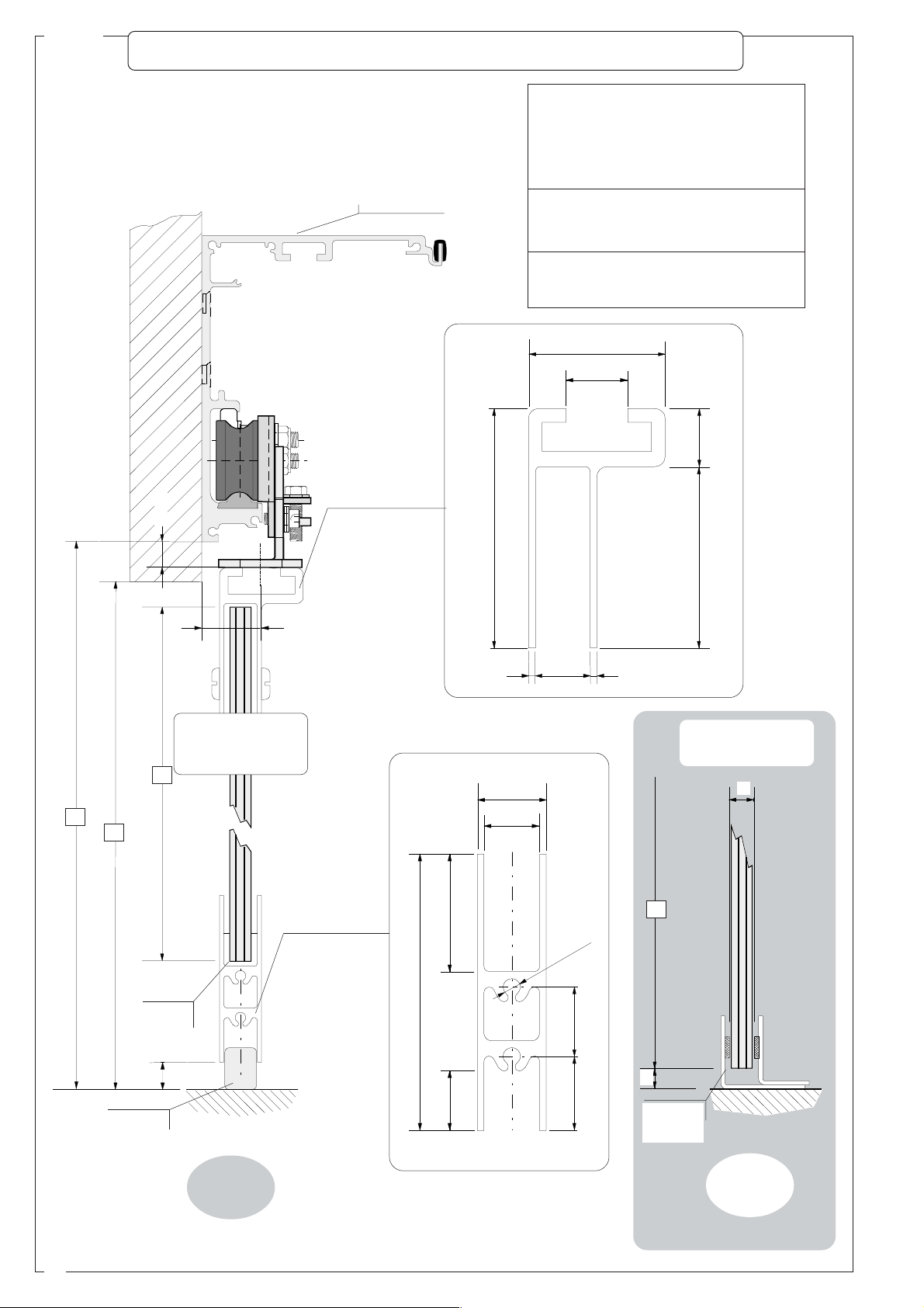
SERIE RODEO
MECHANICAL ADJUSTMENTS
The trolleys can be used to adjust the
alignment of the door wings as follows:
- vertical adjustment RV, with bolts
and nuts A and B
- transverse adjustment R
bolts and nuts C
T
, with
4
- 4 mm
+4 mm
DD
D
DD
- horizontal adjustment RO, with
bolts and nuts D and E
EE
E
EE
4
+6 mm
- 6 mm
BB
B
BB
10
AA
A
AA
4
+6 mm
13
10
- 6 mm
CC
C
CC
Page 11

MECHANICAL ADJUSTMENTS
SERIE RODEO
VERTICAL ADJUSTMENT R
V
To obtain correct vertical alignment of the door wings, adjust
the trolleys as follows :
- Loosen screws A.
- Turn vertical adjustment screw B until the door wing(s) is/
are as perpendicular to the ground as possible. If the
automation system is being used to power two sliding door
wings, adjust this screw so that no gap is left between the
door wings when they are closed.
- After completing the adjustments, tighten screws A and
move the door wing manually to make sure that there is no
mechanical interference between the moving door wing(s)
and the pavement along the entire line of movement.
If necessary, the entire door wing can be raised by adjusting
both trolleys.
TT
T
TRANSVERSE ADJUSTMENT RTRANSVERSE ADJUSTMENT R
TRANSVERSE ADJUSTMENT R
TRANSVERSE ADJUSTMENT RTRANSVERSE ADJUSTMENT R
TT
The vertical plane of the rollers on the trolleys must be parallel with the beam. If the trolleys are
out of alignment (i.e., if the door wing does not slide
easily), proceed as follows:
- Loosen nuts and bolts
CC
C;
CC
- Align the trolleys with the guide track (for example, by
measuring distance Q between the body of the trolley
and the beam);
- Move the door wing manually to make sure that there
is no mechanical interference between the moving door
wing(s) and
non-moving
parts/door
wings along
the entire line
of movement.
Profile of beam
- Tighten the
bolts firmly to
fasten the
Door wing
trolleys.
Profile of beam
g
in
w
r
o
o
D
G
u
i
d
e
t
r
a
c
k
G
u
i
d
e
t
r
a
c
k
HORIZONTAL ADJUSTMENT R
O
(for Rodeo 2, only)
For fine adjustment (± 4 mm) of
the point where the two door
wings meet, loosen nuts and
bolts D and move the two door
wings at the same time.
To obtain a coarser adjustment,
remove the belt attachment
system by loosening nuts and
bolts E.
After adjustment, tighten the
bolts back down.
11
Page 12

SERIE RODEO
MECHANICAL ADJUSTMENTS
ADJUSTING THE BELT TENSION
If necessary, the idle pulley
can be used to adjust the
tension on the belt. Proceed
as follows:
1) Loosen the mounting
screws on the pulley.
2)Rotate the adjustment
screw until the correct belt
tension is obtained.
3)Tighten the mounting
screws carefully to maintain
the correct tension.
Mounting screw
Mounting screw
Pulley clamping crewsScrew for adjusting belt tension
ANTI-VIBRATION BRACKET ON THE PROFILE HOUSING
This bracket prevents the (optional) profile housing from
oscillating and bending longitudinally. One bracket can be
installed when the beam is mounted at a height of up to 2.80
m, while both brackets should be installed if beam height
exceeds 2.80 m. If necessary, the bracket may be bent into
the required shape.
ADJUSTING THE MECHANICAL STOPS
The mechanical stops are used to set and adjust the
opening width of the door wings so that they do not move
beyond the ends of their travel.
Loosen the mounting screws and move these stops to
the proper positions.
N.B.: The mechanical stops must be correctly placed
and tightened to prevent damage to the guide track and
permit its adjustment.
PLACEMENT OF
MECHANICAL STOPS
ANTI-VIBRATION BRACKETS
12
AND
Page 13

MECHANICAL ADJUSTMENTS
BELT SUPPORT
The belt support is used to control belt vibration. It is installed at the centre of automation
systems powering two door wings whose support profile exceeds 3020 mm in length. If
necessary, the support may be bent into the required shape.
N.B. Make sure that the belt support does not come into contact with moving parts during
operation.
Mouting screw
Belt support
SERIE RODEO
CHECKING FOR PROPER ASSEMBLY
After the beam has been installed and all mechanical
adjustments have been made, made sure that:
_ no scraps of materials left by manufacturing processes
remain on the guide track, which would damage the track
and/or the trolley wheels;
_ no foreign objects and/or tools have been left on the inside
of the beam;
_ the door wings are properly aligned and the mechanical
stops have been correctly positioned as described above.
Before applying power to the automation system, check for
proper operation by opening and closing the system manually
(push directly on the door wings to perform this check).
13
Page 14

SERIE RODEO
ZP8 ELECTRICAL CABINET
CONNECTION FOR ELECTRIC LOCK
MA7012
CONNECTION FOR "COMPASS"
OPERATING SYSTEM
10
11
F1 F2 ES ES TX RX GND 1 2 3 4 5 6 7
1
2
MA7012 BUSSOLA MA7041
C1
Ri
M
R2
+
R1
2
-
P.R.AP AP/PARZ TCA V.RALL.CH V/CH V/AP P.R.CH FRENO V.RALL.AP.
SEAT FOR PHOTOCELL CARD
TERMINAL BOARD FOR CONNECTION
ACCESSORIES
OF
MF9011 - MF9111 MA7032
9011-9111
MF
CONNECTION FOR FUNCTION SWITCH
MA7041
RAPID
-BLOW 1.6A FUSE ON
ACCESSORIES
12345678
FUSIBILE
ACCESSORI
1,6A
21 345678910O
N
DIP-SWITCHES
ADJUSTMENT TRIMMERS
2134O
N
SEAT FOR EMERGENCY OPERATION CARD
INDICATOR LEDS
RESET KEY
RESET
APRE
7032
MA
TERMINAL
MOTOR
OPEN KEY
BOARD FOR CONNECTION OF
-ENCODER- BATTERY-POWER
SUPPLY
POWER SUPPLY CONNECTION TERMINAL BOARD
24V
M
N
E
S
S
E
-
BATT.
+
24AC
24AC
+
-
24V Reduction gear power supply (supplied standard)
Earth connection
230V Power supply (50/60 Hz)
Line fuse 2A
24V
230V
(see page 22)
TERMINAL BOARD FOR CONNECTION OF ACCESSORIES
+
10
-
11
1
2
C1
Ri
M
R2
R1
2
F1 F2 ES ES
MA7012
+
-
P.R. AP
- Contact 1-2 and 2-C1 are normally closed (N.C.) and bridged together at the factory. To use these functions, replace
the bridge connections with the relative devices.
10 - 11 24V a.c./d.c. power to accessories
1- 2 Pushbutton Stop, normally close contact (N.C.)
2- C1Photocells, re-opening during closing (N.C.)
2- RiNormally open contact (N.O.) for central sensor (used only
when interface system is installed)
2- R1Normally open contact (N.O.) external sensor (can be excluded)
2- R2Normally open contact (N.O.) internal sensor
2- M Normally open contact (N.O.), for "step-by-step" operation
(manual button)
- The 2-C1 contact is used when a security system is desired (for example, photoelectric cells or other control
devices),
which is not capable of being housed in the special clip-in seat. Note: if the MA9011/9111 photoelectric cell
card is not enabled, or if it is enabled and you wish to disable it, set dip switch 3 to ON (4-way module).
- The 2-M contact is normally open (N.O.), and has a double function:
1) During normal functioning it is enabled for opening, even if the MA7041 function selector is set on “doors closed”.
This function can be used for preferential passage, (e.g., evening closure, opening command on key or magnetic
switches).
2) By setting dip switch 5 to ON (10-way module), the “stepper” opening function is enabled (by pressing the button
the door opens; pressing it again closes the door). Attention, by using this function contacts 2-R1 and 2-R2 are
excluded.
14
Page 15

ZP8 ELECTRICAL CABINET
1
SERIE RODEO
678
RESET
The RESET key, resets the data and restarts the automation in
question.
MA7032
2134O
N
APRE
The APRE key, starts automation and completes an opening cycle.
Attention: The function of the open key is excluded if dip switch 5
(10-way module) is set to ON.
IMPORTANT:
Do not perform the following operations, electrical connections/wiring or replacement of circuit cards unless the
mains power has been disconnected and the “+” (red) power terminal has been removed from the emergency
battery (if installed).
ADJUSTMENT TRIMMERS
MF9011 - MF9111
+
-
P.R.AP AP/PARZ TCA V.RALL.CH V/CH V/AP P.R.CH FRENO V.RALL.AP.
! # % '
" $ &
ADJUSTMENTS TRIMMERS
N° 1 2 3 4 5 6 7 8 9
BRAKING
INTENSITY IN
THE INITIAL
SLOWDOWN
PHASE
..................
FUNCTION
VALUE
START
POINT OF
OPENING
SLOWDO-
WN
STARTING
POINT
PARTIA L
OPENING
60 ÷ 90 %
AUTOMA-
TIC
CLOSING
0.5 ÷ 13
SEC.
SLOWDO-
WN
CLOSING
5 ÷ 12
CM/SEC.
CLOSING SPEED OPENING SPEED
RODEO 1
8,6÷55
CM/SEC.
RODEO 2
17,2÷78
CM/SEC.
CORSA 1
8,6÷55
CM/SEC.
CORSA 2
17,2÷78
CM/SEC.
START
POINT OF
CLOSING
SLOWDO-
WN
STARTING
POINT
O
N
SLOWDO-
WN
OPENING
5 ÷ 12
CM/SEC.
15
Page 16

SERIE RODEO
SELECTION FUNCTIONS
yaw-01piD SNOITCNUFNOITCELES
1
2
NO
NO
3- .»FFO«noitisopnipidehtpeek,desutoN
4
5
6
8/7
7
8
7
8
8/7
01/9
9
01
01/9
NO
NO
NO
NO
NO
FFO
FFO
NO
FFO
NO
FFO
NO
FFO
.)71.gapnoitarbilacgniruddesu(egarotsretemaraP
.)81.gapees,2307AMtihw(ycnegremeehtnolevelegrahcehtgnikcehC
gnisolcelihwhsuptnatsnoC
.)41.gap,M-2tcatnocees(noitarepo"pets-yb-petS"
.)02.gap"metsysecafretniehtgnillatsni"ees(metsysnoitamotuarehtohtiwecafretnI
.)91.gapees(kcolcirtceledelbasiD
91.gapees)desolcdnaneposroodskcol(kcolfonoitareposuounitnoC
91.gapees)desolcsroodskcol(kcolfonoitareposuounitnoC
91.gap)1407AMhctiwsnoitcnufybdellortnoc(lortnoclacolmorfdegagnesidkcolcirtcelE
)81.gapees(eruliafrewopfoesacnisroodsesolcmetsysycnegremE
)81.gapees(eruliafrewopfoesacnisroodsnepometsysycnegremE
)81.gapees(eruliafrewopfoesacniyrettabycnegremeybderewopnoitarepolamroN
yaw-4piD SNOITCNUFNOITCELES
1
NO
.)91.gapees,rotcelesnoitcnufpid-01
2 - »FFO«noitisopnipidehtpeek,desutoN
3
NO
)22.gap
4 - »FFO«noitisopnipidehtpeek,desutoN
FUNCTIONS OF INDICATOR LED
IBILE
LED STATUS SIGNAL
1 flashing -Encoder is inoperative
1 lit -Encoder is inoperative
2 (*) -emergency battery is discharged
3 lit -pilot light on 24V a.c.
4 lit -photocell contact open
5 lit -interface function activated (see "installing the interface")
6 lit -malfunction on electrick lock
7 lit -pilot light on amperometric sensor
8 flashing -automatic closing cycle in progress
8 flashing -"read" error during automatic calibration cycle
6/7/8 lits -automatic calibration procedure terminated
,gnisolcelihwhsuptnatsnoc,NOot4hctiwspidtes(ecivedcinap-itnadedaol-gnirpsfonoitavitcA
,draoblortnocehtotnidetresnidrac1119FMro1109FM(noitcnuflleccirtceleotohpehtsedulcxE
12345678
(*) in this case, the LED signal remains lit to indicate that the anti-panic device batteries are run down only if the
emergency battery status check is disabled (10-way dip 2 set to OFF); whereas it flashes if the battery check is activated
(10-way dip 2 set to ON).
16
Page 17

SERIE RODEO
STARTING UP THE SYSTEM
VERIFICHE PRELIMINARI
Before start-up, make sure that:
" The electric lock (if installed) has been manually released;
" The proper tension has been applied to the belt (see p. 12);
" The checks described on p. 13 (checking for proper assembly) have been performed;
" No objects are present along the path taken by the door wings as they move;
" All mounting hardware has been properly tightened;
" The sensors are correctly aligned and are not blocked;
" The desired functions have been correctly selected on the dip switches (see p. 16);
" The trimmers have been set to their midpoints (see p. 15),
START-UP/CALIBRATION
1. Turn on the power to the unit
- LED no. 3 will light up
2. Move dip switch 1 to ON
- LED no. 3 will turn off and LED no. 8 will light up
- The system will execute an closing and opening cycle at reduced speed and will stop at the maximum open
position
- LEDs no. 6-7-8 will light up
3. Move dip switch 1 to OFF
- LEDs no. 6-7-8 will turn off and LED no. 3 will light up
4. Make sure that function switch MA7041 (if installed) has been set to the “open” position (with the LEDs lit in
sequence)
5. Enter an "open" command on 2-R1/2-R2 or by pressing the open key (see p.15).
-the automation will position itself at the closing point
6. Send an opening signal -
-the automation will perform a complete manoeuvre
7. Adjust the movement of the doors using the door trimmers (see p.15).
8. Adjust trimmer 3 to obtain the desired delay before automatic closing
9. Trimmer 2 can be adjusted only if function switch MA7041 has been installed and if this switch has been set
to the “partial opening” position
10. Use the lever on the manual release system to re-arm the electric lock (if installed)
(
1)
If the automation system stops during the closing cycle, the motor polarity may be incorrect. If this occurs, proceed as
follows:
cabinet (on the right)
(1)
at the end of the cycle
-
Disconnect the mains power
-
Make sure dip switch 1 is set to OFF
-
Reverse connections M-N on the terminal board for the motor, which is located in the electrical
-
Begin another start-up/calibration procedure starting from point 1.
SAFETY FUNCTIONS - Actions taken by the automation system when a safety device trips
the safety sensor detects an obstacle, the microprocessor control system in the electrical cabinet
When
actuates:
re-opening, if the automation system is closing;
a stop, if the automation system is opening. The system will then re-close when
actuated by the automatic closing timer.
If the obstacle is still detected:
during closing the automation will automatically try 4 times to close the doors, and then it
will stop them in the open position, awaiting a new command.
during opening the automation system will stop with the door wings resting against the
obstacle and will re-close when actuated by the automatic closing timer.
It repeats the checking operation at every opening command and resets with
the following manoeuvre when the obstacle has been eliminated.
(In both cases, normal operation with the programmed settings will automatically resume when the obstacle
is removed )
Changing the direction of door opening (Rodeo 1)
- With the door stopped, reverse connections M-N on the terminal board for the motor, which is located in the
electrical cabinet (on the right);
- Re-align electric lock MA7012.
- Press the RESET key on the electrical cabinet (if the unit has already been calibrated, the relative settings
will be deleted).
- Start up (or restart) the automation system as described in the section on start-up.
17
Page 18

SERIE RODEO
INSTALLATION OF ACCESSORIES (available upon request)
MA7032 - Battery-powered emergency system
This emergency system opens the door in case of power failure. It includes a pair of 12V (1.2Ah) batteries as
well as a circuit card that keeps the batteries charged and distributes power to the automation system.
By using dip switches 9 and 10 (10-way module), the emergency system can be programmed to operate in the
following ways when the power fails:
Note: When functioning is interlocked (see p. 20), the following functions are selected equally for both automations.
9 OFF Opening only. The doors open and remain open
10 ON until current returns to the line. The same occurs
even if the MA7041 selector is set to “doors closed”.
12345678910
9ON Closing only. The doors closes and stays closed
10 ON (even if "door open" has been selected on MA7041)
12345678910
until the mains power is restored.
9 OFF Normal functioning. The doors continue to function
10 OFF until the current in the batteries drops below the
12345678910
safety level, in which case they stop. If the MA7041
function selector is set to “doors closed”, the doors
can only be opened by entering a command on the
2-M contact.
Note: in case the MA7041 selector is not connected
XGND 1234567
SOLA MA7041
1 2 3 4 5 6 7
MF9011 - MF9111
and you wish to activate the antipanic function, bond
contacts 1-3 as shown in the figure.
Anti-panic device with constant battery control
Setting dip switch 2 of the 10-way module to the ON position (on the
interlock system, set it on both panels) activates the constant control of
the battery charge buffer, which during normal functioning with 230V
power mains voltage checks the minimum charge of the 20V batteries; if
12345678910
it falls below this level (on the interlock system the voltage of the batteries
of one of the two automations) the function activates a safety procedure. This procedure consists in the opening
or closing of the doors (depending on the settings of dip switches 9 and 10). For the interlock system, the safety
procedure (signalled by a continual flashing of LED No. 2 on the MASTER panel) causes the doors to open on
both the automatic system. After reset of the batteries, the LED goes out and the system re-starts normally after
an ‘open’ command.
N.B.:
For single automation installations, activating the battery control deactivates normal functioning (dip 9
OFF – 10 OFF).
- If function switch MA7041 is installed, make sure that the “
EMERGENCY
” function has been selected (which
is indicated by a flashing yellow LED).
- In any event, normal operation with the programmed settings will automatically resume when the mains power
is restored.
18
Page 19

SERIE RODEO
INSTALLATION OF ACCESSORIES (available upon request)
MA7012 - Electric lock
Electro-mechanical system for locking the door wings, with gravity-powered mechanical locking action and
electric unlocking system. This device locks the door wing(s) in the closed position (and/or in the open position)
by engaging a bracket installed on one of the trolleys.
By using dip switches 7 and 8 (10-way module), the electric lock can be programmed to operate as follows:
7 ON Deactivated. Use this setting when the electric lock is
8 ON not installed.
12345678910
7 OFF Locking with doors closed. This is normal operation:
8 ON the unit locks on closure and is released electrically when
12345678910
the open command is given. This is the default setting.
7 ON Locking with doors closed and open. The unit locks
8 OFF both when open and closed (when positioned correctly
(1)
12345678910
), and is released electrically by each open and close
command.
7 OFF Delayed locking. The electric lock is unlocked when
8 OFF the first “open” command is given at initial start-up or
after a power failure, or when “door open” is selected
12345678910
on MA7041. The lock is locked when “door closed” or
"output only" is selected on MA7041.
MI1010 - Spring-loaded Anti-panic device
Mechanical device to open the doors, made up of a spring-loaded system which operates without electric
power supply. With this device, use the dip-switches as indicated.
DIP SWITCH
10-WAY
DIP SWITCH
4-WAY
4 ON Activation of constant push while closing.
(10-way dip switch)
12345678910
1234
1 ON Activation of spring-loaded anti-panic device.
(4-way dip switch)
19
Page 20

SERIE RODEO
0
C
M
M
NE+S
S
.
C
C
0
C
M
M
NE+S
S
.
C
C
INTERFACE FUNCTION
DIAGRAM OF TWO INTERLOCKED AUTOMATION
1 1 or 2 copies of photoelectric cells
2 Board (MA9011-MA9111)
3 Anti-panic board MA7032
EXTERNAL AUTOMATION (MASTER)
4 Electric lock MA7012
5 Radar (MR8002-MR8104)
6 Function selector MA7041
!
#
F1 F2 Es Es
#
"
1
11
1
2
1
Ri
R2
R1
2
E -
-
BATT
+
24A
24A
"
!
1
11
1
2
1
Ri
R2
R1
2
E -
BATT
+
24A
24A
ENTRY EXIT
CLOSED EMERGEN CY
Cancelli Automatici
F1 F2 Es Es
$
SELECTI ON
#
INTERNAL AUTOMATION (SLAVE)
Operation
When one of the radars is detected (internal or external), the automation opens the relative door and at the
same time locks the other door, triggering a sequence of operations ending with the closing of the second door.
STANDARD SEQUENCE: DETECTION OF OBJECT BY OUTER OR INNER SENSOR
ST
OF 1
OPENING
CLOSING
OPENING
CLOSING
DOOR / DEACTIVATION OF OPPOSITE SENSOR
OF 1ST DOOR
OF 2ND DOOR
OF 2ND DOOR / ACTIVATION OF OPPOSITE SENSOR
The central sensor (intermediate) connected to clamps 2-RI detects the presence of persons between the two
automations, and enables the microprocessor to reopen the automatic system opposite the one that was last
opened, as always using the interlock function.
20
Page 21

Connections required
Connect the accessories to the two panels and to each other using the compass clamp (bussola) according
to the illustrated diagram.
Set dip switch 6 on the outer automation system to ON, which will assign MASTER control status to that system.
All control sensors and function switch MA7041 (if installed) must be connected to the MASTER automation
system, which controls the other automation system.
The photoelectric cells and the anti-panic device must be independent on both automations.
The trimmer adjustments on the two automation system act independently.
If contacts 1-2 and 2-C1 are not used, they must be connected by jumpers on both automations.
ENTRY EXIT
Connection
CLOSED EMERGENCY
for electric lock
MA 701 2
F1 F2 Es Es
Cancelli Automatici
SELECTION
Outer Radar
(2-R1)
Co nne ction for
1 2 3 4 5 6 7
function switch MA 7041
Central Radar
or middle
(2-Ri)
10
11
F1 F2 ES ES TX RX GND 1 2 3 4 5 6 7
1
2
MA7012 B USSOLA MA7041
C1
Ri
M
R2
R1
2
MF9011 - MF9111 MA7032
+
-
P.R.AP AP/PARZ TCA V.RALL.CH V/CH V/AP P.R.CH FRENO V.RALL.AP.
MF9011-9111 MA7032
A C
C Nc 1 0
A2 C1 A1
M
N
+
E
S
S
-
E
-
BATT.
+
24AC
24AC
Emergency Ba ttery
+
_
+
_
CONTROL
PANEL
MASTER
(
)
BUSSOLA
TX RX GND
SERIE RODEO
Inner Radar
(2-R2)
Connection
for electric lock
MA 701 2
10
11
F1F2ESES TXRXGND1234567
1
2
MA7012 BUSSOLA MA7041
C1
Ri
M
R2
R1
2
MF9011 - MF9111 MA7032
+
-
P.R.AP AP/PARZ TCA V.RALL.CH V/CH V/AP P.R.CH FRENO V.RALL.AP.
MF9011-9111 MA7032
A C
C Nc 1 0
A2 C1 A1
12 V 1.2Ah 12 V 1.2Ah
Bridge connection
for set of batteries
F1 F2 Es Es
M
N
+
E
S
S
-
E
-
BATT.
+
24AC
24AC
Emergency Ba ttery
+_+
_
CONTROL
PANEL
SLAVE
(
)
TX RX GND
BUSSOLA
12 V 1.2Ah 12 V 1.2Ah
Bridge connection
for set of batteries
21
Page 22

SERIE RODEO
y
CONNECTION OF ACCESSORIES TO THE PANEL
FOREWORD
To facilitate the wiring procedure, the entire length of the beam is equipped with a space for lodging and distributing
the cables.
Two no.2 (common) terminals have been provided on the terminal board for connection of accessories.
The power cables should be arranged on the left side of the beam, where the transformer is located.
The mains power and ground connection are connected to this transformer.
ENTRY EXIT
CLOSED EMERGENCY
230V24V
Fuse 2A 250V
Connection for function
switch MA 7012
10
11
F1 F2 ES ES TX RXGND 1 2 3 4 5 6 7
1
2
MA7012 BUSSOLA MA7041
C1
Ri
M
R2
R1
2
MF9011 - MF9111
+
-
P.R.AP AP/PARZ TCA V.RALL.CH V/CH V/A P P.R.CH FRENO V.RALL.AP.
MF9011-9111
A C
C Nc 1 0
A2 C1 A1
F1 F2 Es Es
Connection for function
switch MA 7041
12345678
FUSIBILE
ACCESSORI
1,6A
MA7032
21 34567 8910O
N
21
34O
N
MA7032
RESET
Cancelli Automatici
SELECTION
1 2 3 4 5 6 7
M
N
+
E
S
S
-
E
-
BATT.
+
APRE
24AC
24AC
Emergency batter
_
+
+
12 V 1.2A h 12 V 1. 2Ah
_
Bridge connection
for set of batteries
L1
230V a.c.
L2
Power supply
SEQUENCE OF CONNECTIONS
" CONNECT OUTER SENSOR TO TERMINALS 2-R1 ON THE TERMINAL BOARD IN THE ELECTRICAL CABINET
" CONNECT INNER SENSOR TO TERMINALS 2-R2 ON THE TERMINAL BOARD IN THE ELECTRICAL CABINET
" CONNECT SENSOR POWER TO TERMINALS 10-11 ON THE TERMINAL BOARD IN THE ELECTRICAL CABINET
" CONNECT MAINS POWER
(1)
TO THE RELATIVE TERMINALS ON THE TRANSFORMER
(2)
" CONNECT THE GROUND LEAD TO THE RELATIVE TERMINAL ON THE TRANSFORMER
(1)
P
ROTECTED BY
(2)
IF 24V A.C.
For 001MA7032
The leads for connecting the two batteries have been provided. Simply connect the batteries together using the
bridge connection cable supplied with the system.
For 001MF9011-9111
All that is needed is to insert the amplifier card into its appropriate place after connecting the sensors.
N.B.: If the card is not used, set dip switch 3 to ON (4-way dip switch).
No other connections are required. Bridge connection 2-C1 remains connected.
22
30MA
DIFFERENTIAL SAFETY SWITCH
+ 5A
CIRCUIT BREAKER (AS FOR ITALIAN LAW
46/90)
POWER IS USED, THIS CONNECTION CAN BE MADE DIRECTLY ON THE TERMINAL BOARD IN THE ELECTRICAL CABINET
.
Page 23

ACCESSORIES
SERIE RODEO
SAFETY
MF 9011 Pair of photocells with range of 7m.
MF 9111 Double pair of photocells
with range of 7 m.
MA 7012 Electric lock, complete with release
cord.
MA 7032 Emergency system, complete with
batteries, for CORSA and RODEO
systems.
CONTROL
MA 7041 Function switch
MR 8001 Narrow-field radar
MR 8002 Wide-field radar
MP 8030 Sensitive platform, 800 mm x 300 mm
MP 8060 Sensitive platform, 800 mm x 600 mm
MR 8104 Radar microware, 3 m max
MR 8105 Radar microware, 5 m max
MS 9502 Opening Sensor touch-type
MR 8334-70-90 Safety radar K4
MRT001 Remote control for MR8104 e MR8105
FOR DOOR WINGS WITH FRAME FOR GLASS DOOR WINGS
(with max thickness of 10 mm.)
Complete kit for connecting with EXTERNAL floor
guidE RUNNERS to 10-mm GLASS doors (to be
used with MA7370/7470/7570)
MA 7353 L 1000 mm
MA 7453 L 1500 mm
MA 7553 L 2000 mm
Kit complet pour fixer les VANTAUX En VERRE de
10mm, avec patinS DE guidaGE INTERNES au sol (a
utiliser avec MA7370/7470/7570)
MA 7353 L 1000 mm
MA 7453 L 1500 mm
MA 7553 L 2000 mm
Complete kit for connecting with INTERNAL floor
guidE RUNNERS to Framed doors (to be used with
MA7371/7471/7571)
MA 7351 L 1000 mm
MA 7451 L 1500 mm
Complete kit for connecting with EXTERNAL floor
guidE RUNNERS to 10-mm GLASS doors
MA 7370 L 1000 mm
MA 7470 L 1500 mm
MA 7570 L 2000 mm
MA 7551 L 2000 mm
MAM 600 Central weather stripping for sliding glass
MAM 601 Lateral weather stripping for non-moving
BREAKTHROUGH ANTI-PANIC SYSTEM for:
MI 6010 1 mobile door (L=1,100 mm per door)
MI 6110 1 mobile door (L=1,500 mm per door)
MI 6020 2 mobile doors (L=1,100 mm per door)
MI 6120 2 mobile doors (L=1,500 mm per door)
MI 6030 1 mobile door and 1 fixed door (L=1,100 mm per door)
MI 6130 1 mobile door and 1 fixed door (L=1,500 mm per door)
MI 6040 2 mobile doors and 2 fixed doors (L=1,100 mm per door)
MI 6140 2 mobile doors and 2 fixed doors (L=1,500 mm per door)
doors (package of 30 m.)
and sliding glass doors (package of 30 m.)
OUR S20 AND S40 SYSTEMS ARE ALSO AVAILABLE FOR THE COMPLETE CONSTRUCTION OF
SLIDING ALUMINIUM DOORS. THESE SYSTEMS ARE SPECIALLY DESIGNED FOR USE WITH
RODEO AUTOMATION SYSTEMS.
23
Page 24

SERIE RODEO
DATE
have not been short-circuited.
POSSIBLE CAUSES
A No power or incorrect power is being supplied from the power mains.
B The fuses are blown.
C Initial programming - lacking or unsuitable
D Function switch is set to the wrong position.
E Electrical connections are wrong.
F Bridge connection 1-2 is missing
G Safety devices are not connected to contacts 2 -C1 and the contacts
H Safety photocells are improperly aligned or inoperative.
I Dip 3 (4-way module) to select
J Motor connections are wrong.
K Encoder is inoperative.
L Circuit card MA7032 for the emergency system is inoperative.
M Batteries are dead.
N Dip 2 (10-way module) activated (function verification on page 18)
O Slow-down adjustments (open and close) inadequate
P Adjustments of the slow-down points (open and close)
Q Speed adjustments (open and close) inadequate
R TCA adjustment, excessive
S ZP7 main board is inoperative.
RIFERIMENTI
A - B - C - D - E - F - J - K - N - S - T - U - V - X - Z
D - E - F - G - H - K - I - J - N - R - S - V - Z
C - D - K - O - P - Q - S - V - W - X - Y - Z
C - H - K - O - P - Q - S - V - W - X - Z
S - Q - W - V - X - Y
O - P - Q - S - V - W - X - Y - Z
E - S - T - U
E - G - H - I - S
positioned.
T Microswitch on electric lock is inoperative.
U The bracket that engages the electric lock to the trolley is incorrectly
E - J - S
non-moving parts (for example: door wings/pavement; non-moving door
wings/moving door wings; moving door wings/pavement-mounted
guides; weather stripping/non-moving door wings)
interference between trolleys and cables).
V Mechanical interference is occurring between moving door wings and
D - L - M - N - V - W - X - Y
W There is mechanical interference with the drive system (for example:
X Scraps of materials / objects are present in guide track.
Y Belt tension is incorrect.
Z Mechanical stops are incorrectly positioned.
V - W - X - Y
"
LEDS
INDICATOR
OF
MALFUNCTIONS
- The automation system does not open
Tutti i dati sono stati controllati con la
massima cura. Non ci assumiamo comunque alcuna responsabilità per
eventuali errori od omissioni.
CANCELLI AUTOMATICI
CAME CANCELLI AUTOMATICI S.P.A.
DOSSON DI CASIER (TREVISO)
(+39) 0422 490960 (+39) 0422 490944
- The automation system does not close
- The automation system does not open completely
All data checked with the maximum care.
However, no liability is accepted for any error
or omission.
ASSISTENZA TECNICA
NUMERO VERDE
800 295830
EB
W
www.came.it
MAIL
E-
info@came.it
FUNCTIONS
"
THE
ON
SECTION
THE
SEE
,
- The automation system does not close completely
- The automation system operates at reduced
speed, only
- The automation does not maintain the initial settings
- The electric lock does not unlock to allow the door to open
- The photocells do not operate
- The automation system does not operate in the
manner selected on the function switch
- The emergency system does not operate
- The automation system is excessively noisy
ALSO
Die Daten wurden mit höchster Sorgfalt
geprüft. Für eventuelle Fehler oder
Auslassungen übernehmen wir keine
Haftung.
SISTEMA QUALITÀ
CERTIFICATO
Toutes les données ont été contrôlées
très soigneusement. Nous n’assumons
de toute façon aucune responsabilité pour
les erreurs ou omissions éventuelles.
CAME LOMBARDIA S.R.L.______COLOGNO M. (MI)
(+39) 02 26708293 (+39) 02 25490288
CAME SUD S.R.L. ___________________NAPOLI
(+39) 081 7524455 (+39) 081 7529109
CAME (AMERICA) L.L.C.____________MIAMI (FL)
(+1) 305 5930227 (+1) 305 5939823
CAME AUTOMATISMOS S.A__________MADRID
(+34) 091 5285009 (+34) 091 4685442
CAME BELGIUM__________________LESSINES
(+32) 068 333014 (+32) 068 338019
SERVICE CENTRE NOTES
Todos los datos se han controlado con
la máxima atención. No obstante no nos
responsabilizamos de los posibles
errores u omisiones.
CAME FRANCE S.A.____NANTERRE CEDEX (PARIS)
(+33) 01 46130505 (+33) 01 46130500
CAME GMBH________KORNTAL BEI (STUTTGART)
(+49) 07 11839590 (+49) 07 118395925
CAME GMBH____________SEEFELD BEI (BERLIN)
(+49) 03 33988390 (+49) 03 339885508
CAME PL SP.ZO.O______________WARSZAWA
(+48) 022 8365076 (+48) 022 8369920
CAME UNITED KINGDOM LTD___NOTTINGHAM
(+44) 01159 387200 (+44) 01159 382694
 Loading...