

Page 1

CHAPTER 1
Hardware –connections
Eletrical Connections
INDEX
Topic page
System Layout Diagram........................................................................................................................................2
Dimensions and securing bases PSE/PSU4000..................................................................................................3
Basic card for RBMP1 - description.....................................................................................................................4
Base card for PSR1 (PSE4000 – PSU4000) – description.....................................................................................5
PSCA1 Card (Automatic Cashier) - description.....................................................................................................6
PC03 – description...................................................................................................................................................7
PSI16 Auxiliary cashier control Description.........................................................................................................8
PSC1 auxiliary cashiers – description...................................................................................................................9
Auxiliary device control – description................................................................................................................10
Parking system layout scheme and technical notes ........................................................................................1 1
Connection to Display .........................................................................................................................................12
Connections for PSM4000 -(RBMP1 <--> Display <--> PC30 <-->PC)...............................................................13
Connections for RBMP1 <--> PSR1 (PSE/PSU) e PSCA1(automatic cashier)...................................................14
Connections for PSM4000 (RBMP1) <--> Traffi c lights ........................................................................................15
Connections for PSM4000 (RBMP1) <--> digital inputs.......................................................................................16
PSM4000 (RBMP1) <--> PSI16 and (PSC1) auxiliary cashiers’ connections.....................................................17
Connections for the PSM4000 (RBMP1) <--> PSIO1............................................................................................18
PSE/PSU4000 connections Barrier or other automation....................................................................................19
Connections for the PSE4000 <---> Loop coil......................................................................................................20
Connections for the PSE/PSU4000 <---> TSP00 transponder sensor................................................................21
DIP SWITCH...........................................................................................................................................................22
CAME CANCELLI AUTOMATICI S.p.A. non si assume alcuna responsabilità per errori o omissioni e si riserva di apportare continuamente le variazioni dovute al progresso tecnologico.
List of addresses PSR1(PSE4000/PSU4000) and PSIO1..................................................................................23
T oken loading procedure .....................................................................................................................................24
Token unloading procedure................................................................................................................................25
Token issuing procedure.....................................................................................................................................26
© CAME CANCELLI AUTOMATICI S.p.A. - 119GT33 - V1 - 06/2003 RBMPARK
Cap.1
1
Page 2
Hardware – Connections
4
E
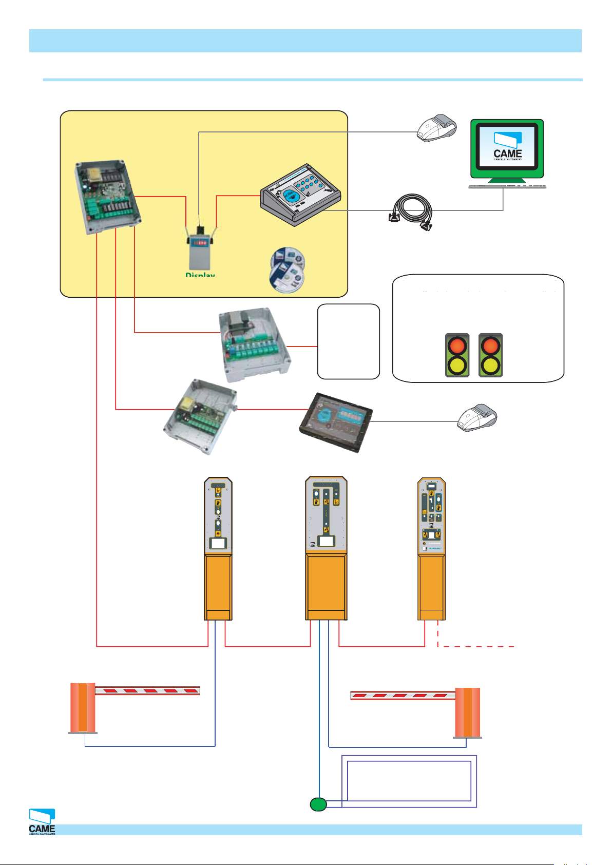
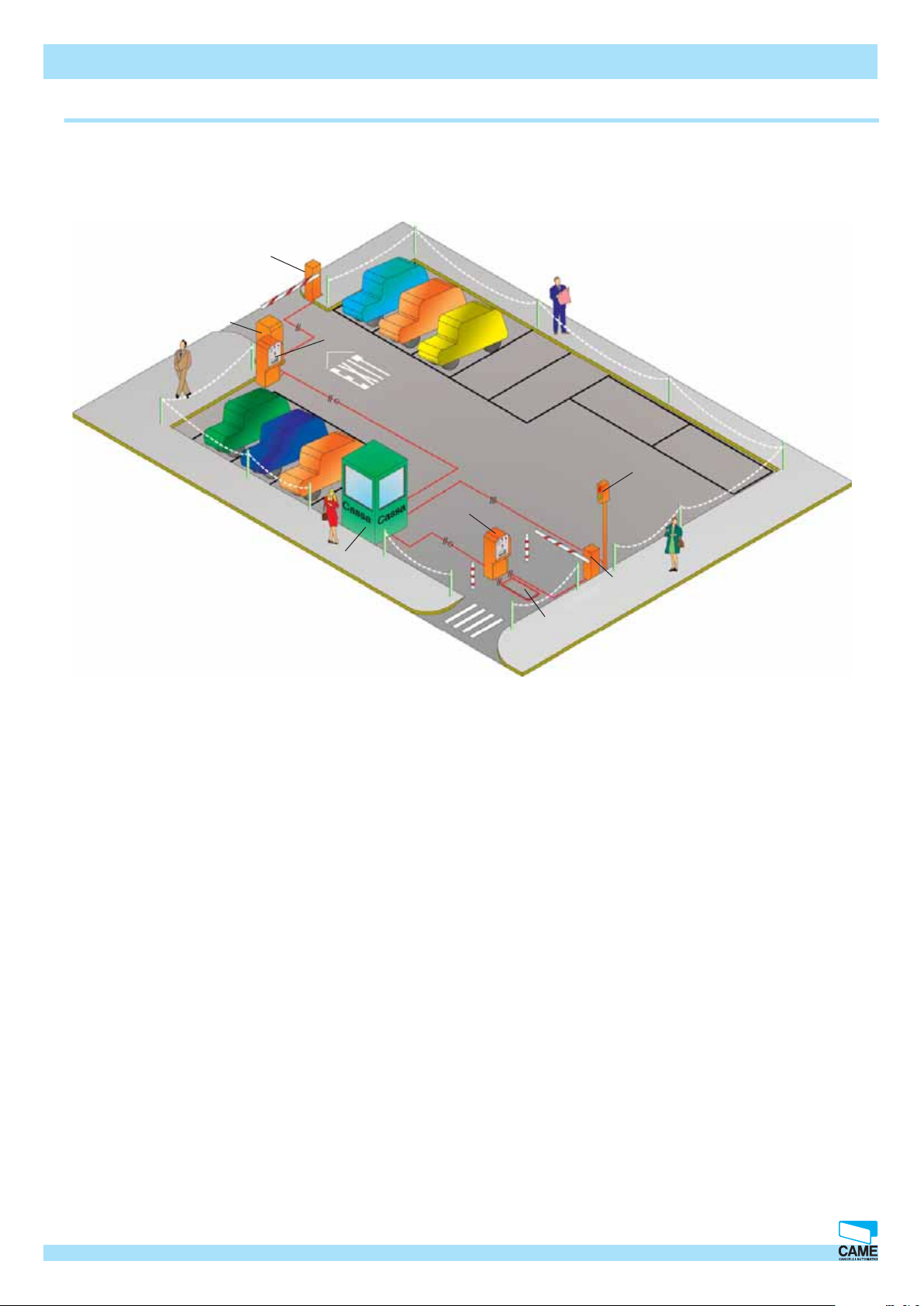
System Layout Diagram
03-#ENTRAL#ONTROL3YSTEM
2"-0%LECTRONIC
#ONTROL5NIT
3CREENEDBIPOLAR
CABLEMINX
MM
3CREENEDBIPOLAR
CABLEMINX
MM
03)!UXILIARY
CASHIERCONTROL
$ISPLAY
03)/!UXILIARY
DEVICECONTROL
UPTOMAX
4HEMAXDISTANCEBETWEEN0#
AND2"-0ISM
0#
4
3
4
.
/
2
0#
)
)#
4
!
/
4
5
!
)
,
,
%
#
#!-%
.
!
#
2BPARK
SOFTWARE
03#!UXILIARYCASHIER
UPTOMAX
23#ABLESTANDARDISSUE
%
%
!
#
&
4
!
4
/
/
4
!
23STANDARDISSUE#ABLE
MLONG
&OREXAMPLE
4RAFFICLIGHTS
,OOPCOILS
3IGNS
,IGHTS
3ENSORS
23STANDARDISSUE#ABLE
RBMP1 - Installation manual
0ERSONAL #OMPUTER WITH
7INDOWS80/3
3ERIAL
0RINTER
4HESYSTEMMANAGESUPTOAMAXIMUMOF
HESYSTEMMANAGESUPTOAMAXIMUMOF
TRAFFIC LIGHTS WHICH CAN BE CONTROLLED
TRAFFIC LIGHTS WHICH CAN BE CONTROLLED
ITHERBYTHE2"-0ORTHE03)/CARD
EITHERBYTHE2"-0ORTHE03)/CARD
3ERIAL
0RINTER
035%XIT
UNITUPTO
MAX
3CREENEDBIPOLAR
CABLEMINX
MM
"ARRIEROROTHERAUTOMATIONDEVICE
"IPOLARCABLEXMM
03%
%NTRANCEUNITUP
TOMAX
#/).
3CREENEDBIPOLAR
CABLEMINX
MM
03#
#/).
!UTOMATIC
#ASHIERUPTO
MAX
3CREENEDBIPOLAR
CABLEMINX
MM
"ARRIEROROTHERAUTOMATIONDEVICE
"IPOLARCABLEXMM
4OTHESUCCESSIVEUNIT
03503%03#
CAME CANCELLI AUTOMATICI S.p.A. non si assume alcuna responsabilità per errori o omissioni e si riserva di apportare continuamente le variazioni dovute al progresso tecnologico.
-AGNETIC,OOP
2 Cap.1 © CAME CANCELLI AUTOMATICI S.p.A. - 119GT33 - V2 - 09/2005 RBMPARK
Page 3
Hardware – Connections
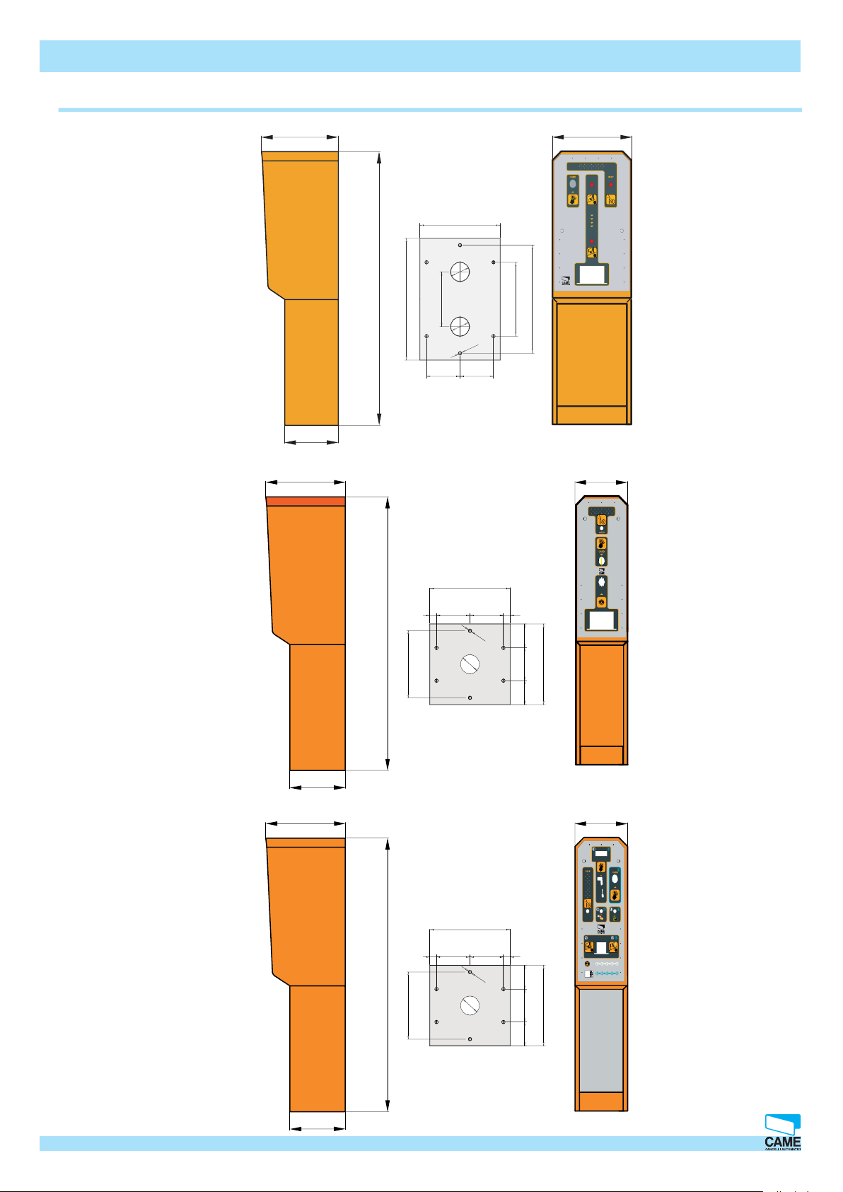
Dimensions and securing basesPSE/PSU4000
03%
Anchoring base
035
D
D
D
RBMP1 - Installation manual
#/).
CAME CANCELLI AUTOMATICI S.p.A. non si assume alcuna responsabilità per errori o omissioni e si riserva di apportare continuamente le variazioni dovute al progresso tecnologico.
D
Anchoring base
03#
D
D
D
#/).
© CAME CANCELLI AUTOMATICI S.p.A. - 119GT33 - V2 - 09/2005 RBMPARK
Anchoring base
Cap.1
3
Page 4
Hardware – Connections
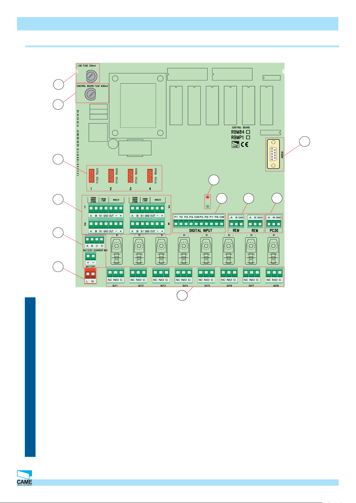
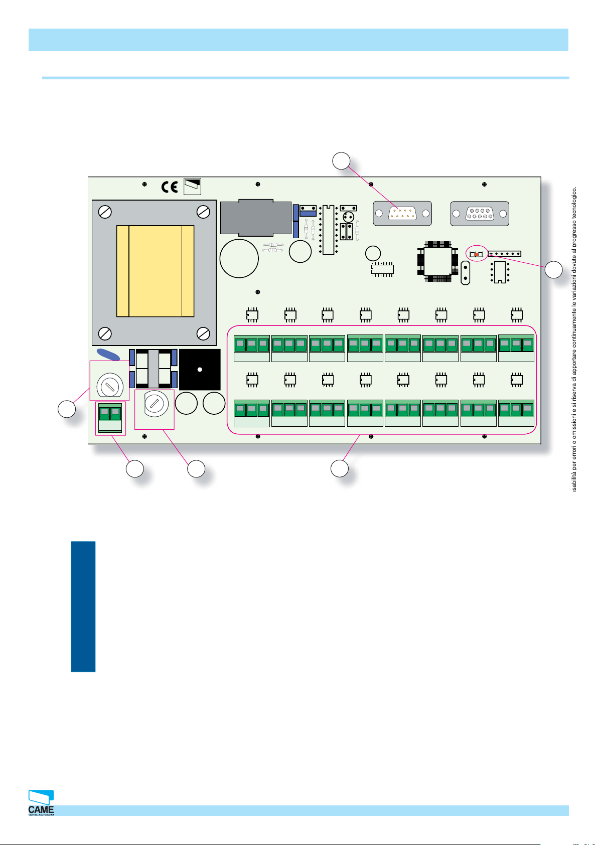
Basic card for RBMP1 - description
1
2
3
4
11
10
9
RBMP1 - Installation manual
12
8
5
6
3
7
1 - Line fuse 315mA
2 - Circuit safety fuse 630mA
3 - (not connected)
4 - (not connected)
5 - Terminal for battery and battery charger connection (optional BN1)
6 - Terminal to power the card
7 - Terminals for connecting controlled devices (automated devices, alarms, traffi c lights, etc.)
8 - Terminal for connecting the PC30.
9 - Terminals for connecting the PSE/PSU units.
CAME CANCELLI AUTOMATICI S.p.A. non si assume alcuna responsabilità per errori o omissioni e si riserva di apportare continuamente le variazioni dovute al progresso tecnologico.
10 - Terminals for connecting incoming digital devices.
11 - Led signalling ‘circuit on’ and ‘communication underway’
12 - Modem connection.
4 Cap.1 © CAME CANCELLI AUTOMATICI S.p.A. - 119GT33 - V2 - 09/2005 RBMPARK
Page 5
Hardware – Connections
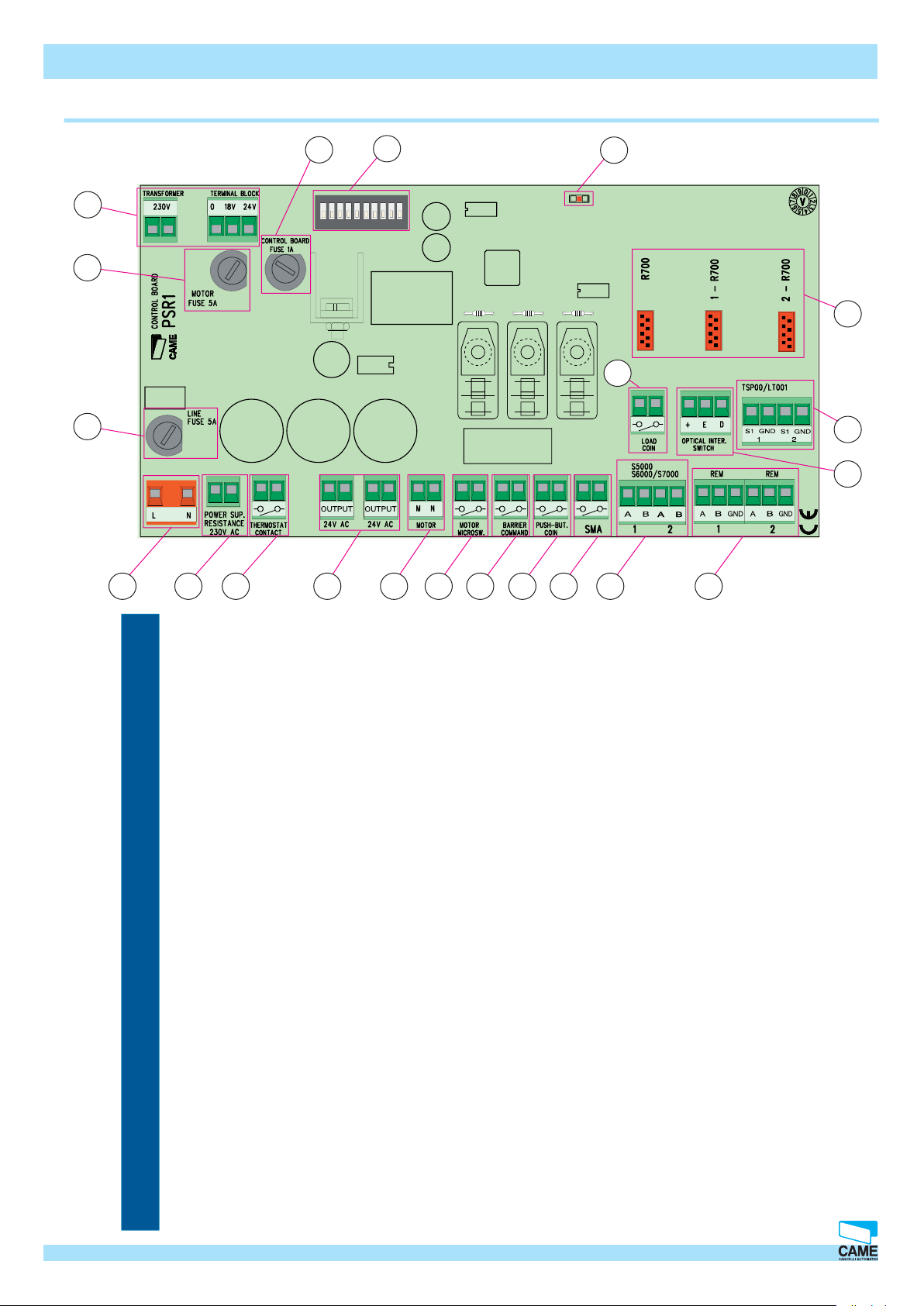
Base card for PSR1 (PSE4000 – PSU4000) – description
21
1
ON
1345
20
2
7
68910
2
3
RBMP1 - Installation Manual
19
18
17
16
15
4
5 6 7 8 9
10 11 12 13 14
1 - Terminals for connecting to the transformer
2 - 5A safety fuse for the coin acceptor
3 - 5A safety fuse from power source and from heating element
4 - Terminals for power supply to the 230V a.c. card
5 - Power supply terminals for heating element
6 - Thermostat contact for heating element control
7 - 24V a.c. Ouptut
8 - Power supply for coin acceptor motor9 9 - Micro-switch for motor control
10 - Terminals for connecting controlled devices (automations)
11 - Token request push- button contact
12 - Loop connection terminals
13 - Keyboard selector connection terminals
14 - Terminals for connecting to RBMP1 or other PSR1 or other RFM
CAME CANCELLI AUTOMATICI S.p.A. non si assume alcuna responsabilità per errori o omissioni e si riserva di apportare continuamente le variazioni dovute al progresso tecnologico.
15 - “Token in” sensor connection
16 - Connection to the TSP00 sensors
17 - Token quantity control contact
18 - R700 – R800 signal decoder cards’ connections
19 - “Circuit On” Led indicator
20 - Dip switch selector
21 - 1A circuit protection safety fuse
© CAME CANCELLI AUTOMATICI S.p.A. - 119GT33 - V2 - 09/2005 RBMPARK
Cap.1
5
Page 6

CONTACT
THERMOSTAT
CONNECTION TO PSCAR1
WARNING!
Hardware – Connections
PSCA1 Card (Automatic Cashier)-description
3 4 5
FUSE 1A
WARNING!
2
RBMP1 - Installation manual
ON
2
1
34
7
5
6
10
89
R700
1 2 3 4 5 6 7 8 9 10 11 12
6
L
N
1
THERMOSTAT
CONTACT
CONNECTION TO PSCAR1
1 - 230V a.c. control board power supply terminals
2 - Power supply and heating element safety fuse
3 - (Control Board) Circuit safety fuse
4 - “Circuit On” signal LED
5 - Dip switch selector
6 - Signal decoding card plug
7 - Terminals for connect ing to RBMP1 or other PSCA1 or PSR1
6
ABGND
ABGND
1
2
7
6 Cap.1 © CAME CANCELLI AUTOMATICI S.p.A. - 119GT33 - V2 - 09/2005 RBMPARK
CAME CANCELLI AUTOMATICI S.p.A. non si assume alcuna responsabilità per errori o omissioni e si riserva di apportare continuamente le variazioni dovute al progresso tecnologico.
Page 7
Hardware – Connections
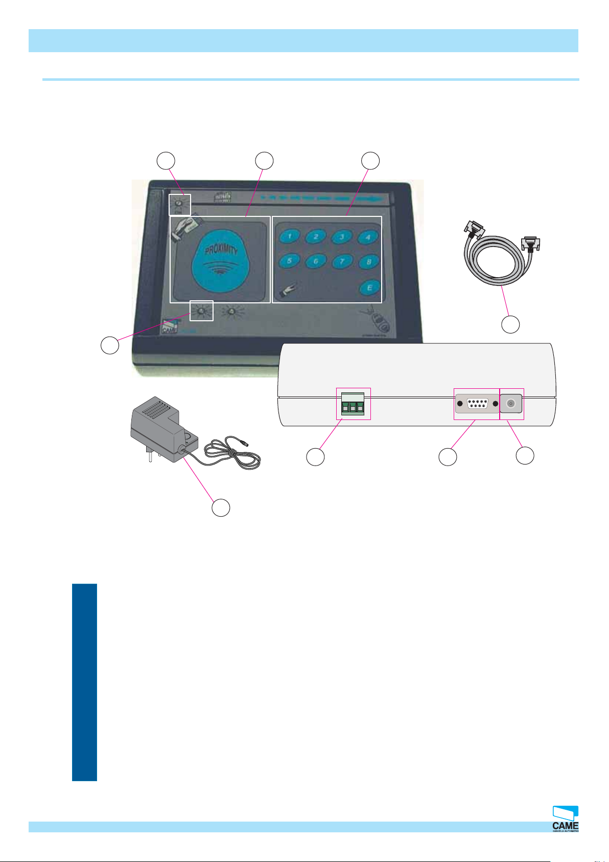
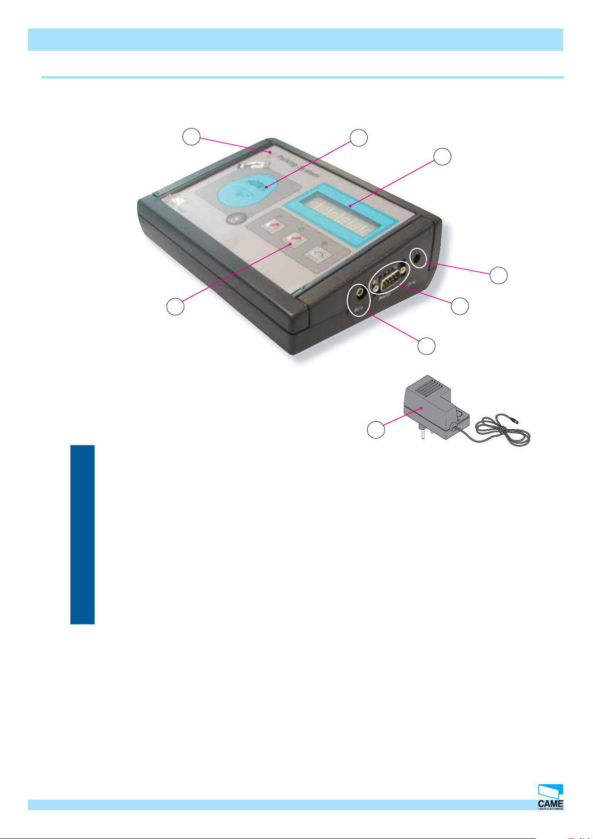
PC03 – description
9
RBMP1 - Installation Manual
8
7 6
5
1 - 12V a.c. Power input
2 - RS232 Serial port for connecting Personal Computer
3 - Terminals for connecting RBMP1 (serial port RS485)
4 - 12V a.c. transformer
CAME CANCELLI AUTOMATICI S.p.A. non si assume alcuna responsabilità per errori o omissioni e si riserva di apportare continuamente le variazioni dovute al progresso tecnologico.
5 - 1.5 m Cable complete with RS232 plugs
GND B A
23
1
4
6 - Keyboard for memorising S5000/S6000/S7000 selector codes
7 - TST01 (proximity cards) memorisation area and GET token reading
8 - “Power on” signal LED
9 - Code signal or proximity card reading LED
© CAME CANCELLI AUTOMATICI S.p.A. - 119GT33 - V2 - 09/2005 RBMPARK
Cap.1
7
Page 8
Hardware – Connections
1 2 3 4 5 6 7 8 9 10 11 12 03 04 05 06 07 V1 V2 V3 V4 V5
PSI16
LINE FUSE 315mA
CONTROL BOARD
FUSE 630 mA
PROGRAMMING
J4
XTAL3
PSI16 Auxiliary cashier control Description
CONTROL BOARD
CAME
ABGND
RBMP1 - Installation manual
6
5
ABGND
1
ABGND
2
ABGND
3
ABGND
4
ABGND
5
ABGND
6
ABGND
7
8
1
L
N
2
3
1 - Power source safety fuse
2 - 230V a.c. control board power supply terminals
3 - (Control Board) Circuit safety fuse
4 - PSC1 unit connection terminals
5 - “Circuit On” signal LED
6 - RS232 plug for connecting to RBMP1 card
ABGND
9
ABGND
10
ABGND
11
4
ABGND
12
ABGND
13
ABGND
14
ABGND
15
ABGND
16
CAME CANCELLI AUTOMATICI S.p.A. non si assume alcuna responsabilità per errori o omissioni e si riserva di apportare continuamente le variazioni dovute al progresso tecnologico.
8 Cap.1 © CAME CANCELLI AUTOMATICI S.p.A. - 119GT33 - V2 - 09/2005 RBMPARK
Page 9
Hardware – Connections
PSC1 auxiliary cashiers – description
6
5
RBMP1 - Installation manual
7
8
1
2
3
4
1 - 12V a.c. Power input
2 - Socket for serial printer
3 - PSI16 connection plug
4 - 12V a.c. transformer
5 - Push-button panel
6 - “Power on” signal LED
7 - TST01 (proximity cards) memorisation area and GET token reading
8 - Display
The PSC1 unit is an auxiliary cashier that can enable the exit of occasional visitors. It is widely used in
CAME CANCELLI AUTOMATICI S.p.A. non si assume alcuna responsabilità per errori o omissioni e si riserva di apportare continuamente le variazioni dovute al progresso tecnologico.
shopping malls or supermarkets because it allows for several units to be installed and the parking area to be
managed in discounted or complimentary fashion for those doing their shopping at said locations.
© CAME CANCELLI AUTOMATICI S.p.A. - 119GT33 - V2 - 09/2005 RBMPARK
Cap.1
9
Page 10
Hardware – Connections
CAME
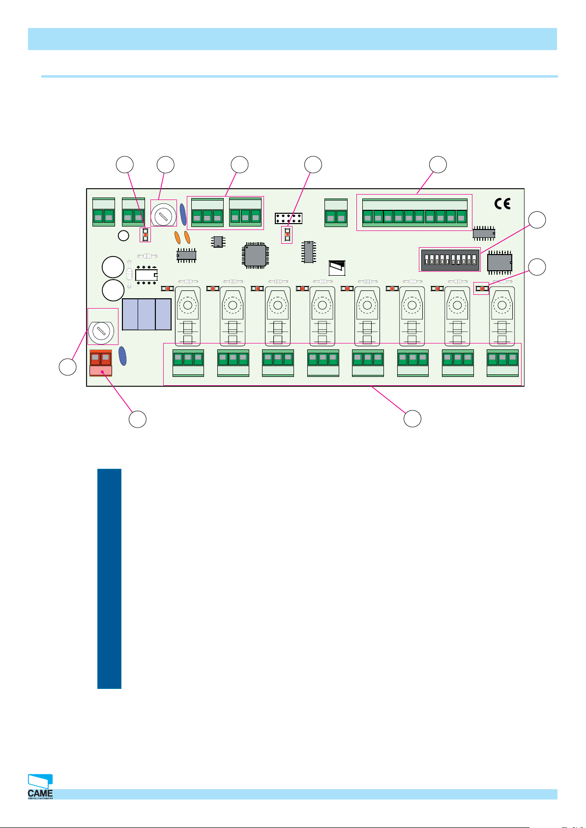
Auxiliary device control – description
3
TRANSFORMER TERMINAL BLOCK
230 V 0V 24V
CONTROL BOARD
U2
LINE FUSE 5A
ABGND
FUSE 630mA
4
ABGND
RBMP1 - Installation manual
P5
5
P6 P7 P8
910
TAM PER
P1
P2 P3 P4 Com Com
6
ON
2
PSIO1
1345
7
68910
7
1 2 3 4 5 6 7 8 9 10 11 12 03 04 05 06 07 V1 V2 V3 V4 V5
2
L
N
230V AC
1
NC NO
ABGND
OUT 1
C NONC C NO CNC NO CNC NO CNC NO CNC NO CNC NO CNCL N
ABGND
OUT 2
ABGND
OUT 3
ABGND
OUT 4
ABGND
OUT 5
ABGND
OUT 6
ABGND
OUT 7
ABGND
OUT 8
8
1 - 230V a.c. card power terminals
2 - Fusibile di protezione dall’alimentazione
3 - PSI01 card safety fuse
4 - Terminals for connecting to RBMP1 or other PSI01
5 - Terminals for connecting to digital devices (loop coils, photocells…)
6 - Dip Switch selector
7 - “Relay on” signal LED
8 - Terminal for connecting controlled devices
9 - “Communication Up” signal LED
CAME CANCELLI AUTOMATICI S.p.A. non si assume alcuna responsabilità per errori o omissioni e si riserva di apportare continuamente le variazioni dovute al progresso tecnologico.
10- “Card powered” signal LED
10 Cap.1 © CAME CANCELLI AUTOMATICI S.p.A. - 119GT33 - V2 - 09/2005 RBMPARK
Page 11
Hardware – Connections
Parking system layout scheme and technical notes
Barrier
PSU4000
PSC4000
PSE4000
PSM4000
RBMP1 - Installation manual
Traffi c light
Barrier
Magnetic loop
When setting up a parking system the following is necessary:
- take into account the space needed by cars to turn when entering: there needs to be enough
space for the vehicles to comfortably access the cashier and collect the token or have their cards
validated. We suggest keeping a distance of 2.5m between the PSE4000 and the barrier. In any
case, please check the shape and size of the system so as to prevent collisions or dangerous
manoeuvres.
- See to delimiting distinct zones or areas with the proper vertical and horizontal signage. This
serves to prevent accidents and render pedestrian exiting operations faster and more composed
as well as to facilitate vehicular access and parking.
- to avoid any potentially dangerous situations for the people in the parking area, for example: height differences, moving parts, low visibility zones, etc..
CAME CANCELLI AUTOMATICI S.p.A. non si assume alcuna responsabilità per errori o omissioni e si riserva di apportare continuamente le variazioni dovute al progresso tecnologico.
Any risk must be reduced to a minimum, using coloured striping, mirrors, photocells and additional lighting.
© CAME CANCELLI AUTOMATICI S.p.A. - 119GT33 - V2 - 09/2005 RBMPARK
Cap.1
11
Page 12
Hardware – Connections
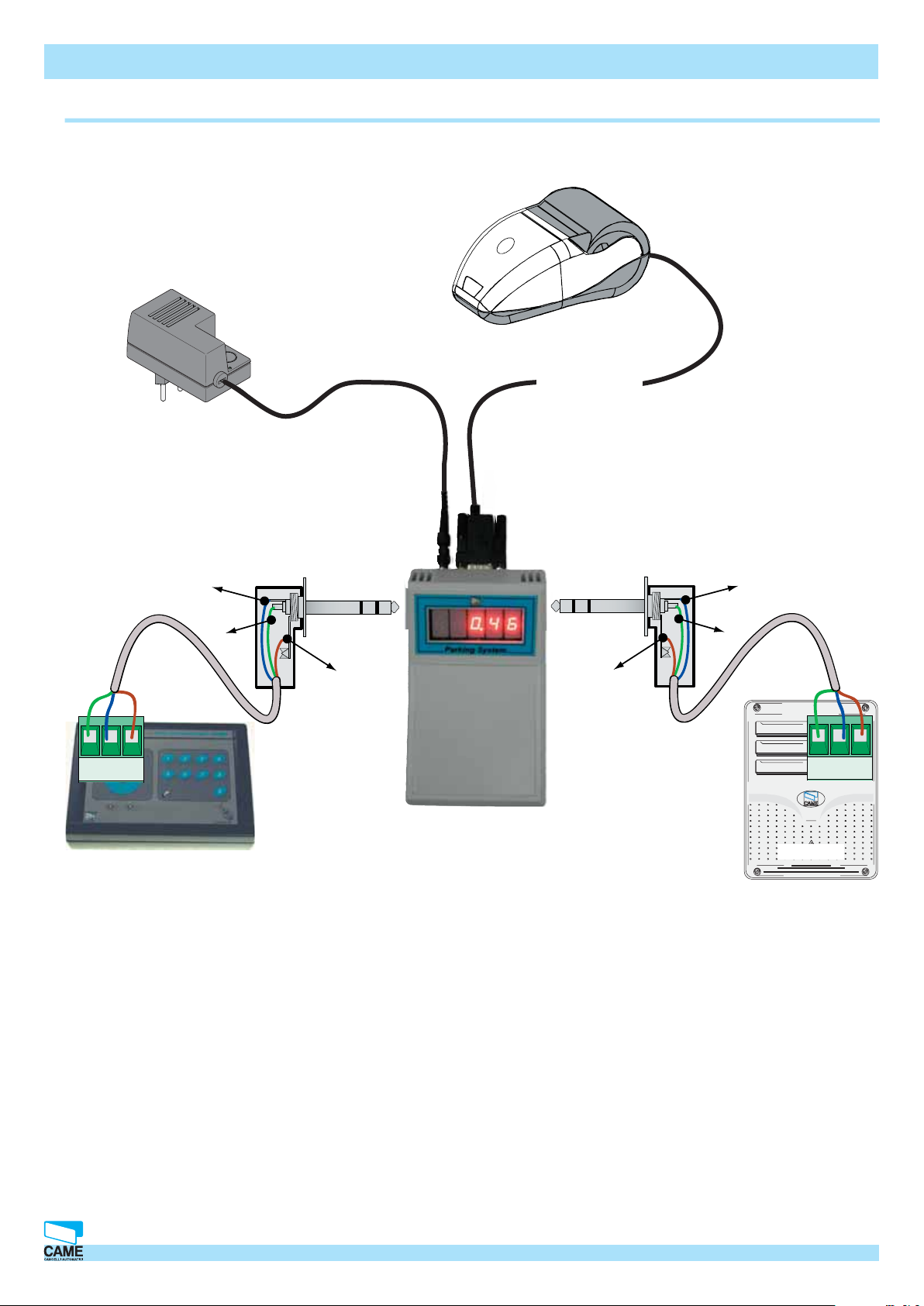
Connection to Display
Connect the supplied 12V a.c.
• for 230V a.c. 50÷60Hz networks
• operating temperature range from -20 to +50 °C
Suggested type of
non supplied cable:
Screened bi-polar
min. 2 x 0.5 mm²
(B)
transformers
Supplied cable
RBMP1 - Installation manual
Suggested type of
non supplied cable:
Screened bi-polar
(B)
min. 2 x 0.5 mm²
(A)
(GND)
A
B
GND
(GND)
(A)
A
B
GND
RBMP1
Please Note: Be careful about the order of the wires, the colour on the display must correspond to the colour
on the RBMP1 (A B GND).
CAME CANCELLI AUTOMATICI S.p.A. non si assume alcuna responsabilità per errori o omissioni e si riserva di apportare continuamente le variazioni dovute al progresso tecnologico.
12 Cap.1 © CAME CANCELLI AUTOMATICI S.p.A. - 119GT33 - V2 - 09/2005 RBMPARK
Page 13
Hardware – Connections
GND B A
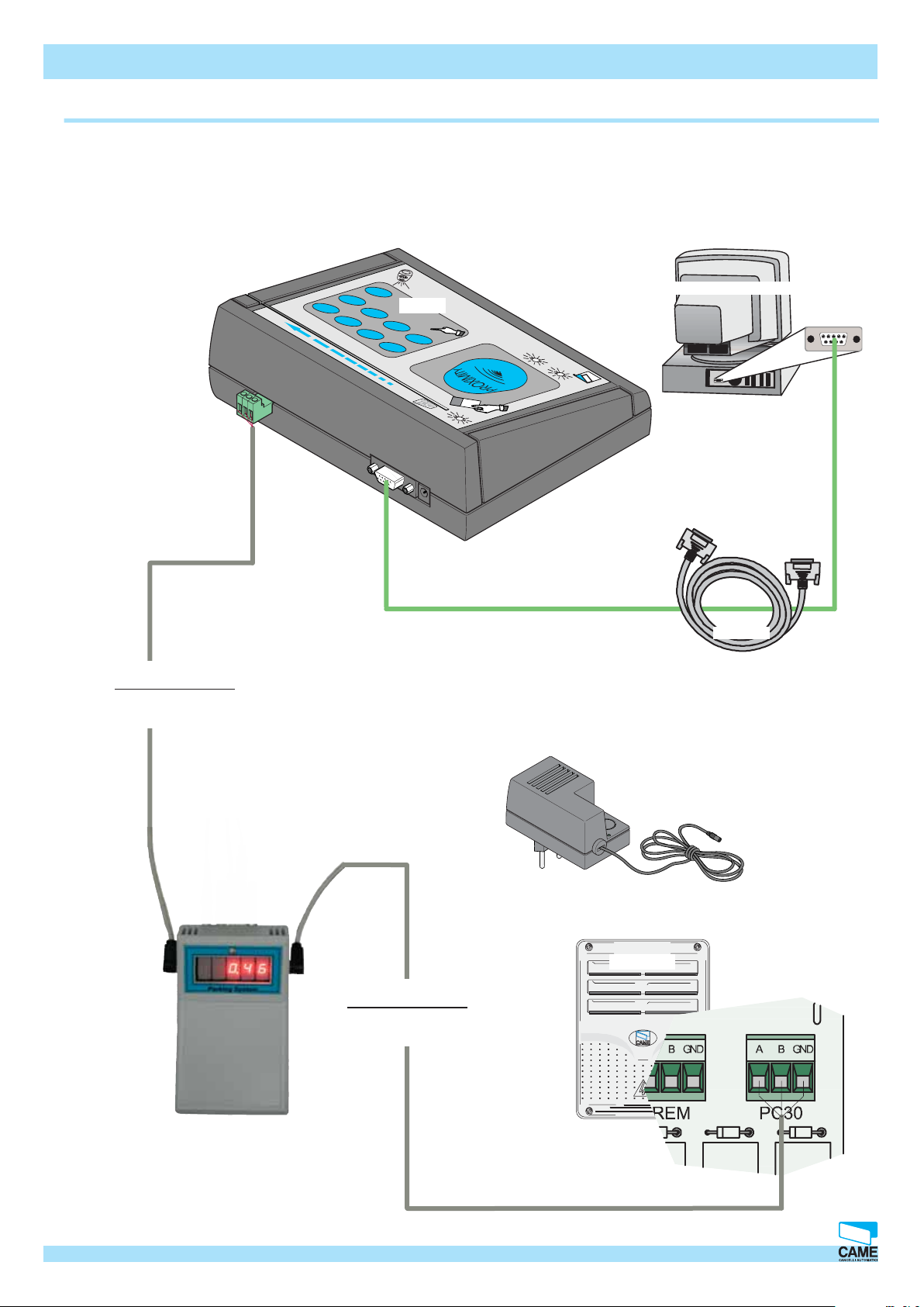
Connections for PSM4000 -(RBMP1 <--> Display <--> PC30 <-->PC)
E
M
CA
PC30
6
5
1
ATOMO - TAM - TFM
TST02
ON
GND B A
E
4
3
78
2
RBMP1 - Installation manual
Personal Computer
PC 30
I
IC
R
I AUTOMAT
L
EL
C
CAN
CAME
1.5 m cable supplied
• forRS232 serial ports
• complete with plugs
Suggested type of
non supplied cable:
Screened bi-polar
min. 2 x 0.5 mm
CAME CANCELLI AUTOMATICI S.p.A. non si assume alcuna responsabilità per errori o omissioni e si riserva di apportare continuamente le variazioni dovute al progresso tecnologico.
2
RS 232
Connect the supplied 12V a.c.
transformers
• for 230V a.c. 50÷60Hz networks
• operating temperature range from -20
to +50 °C
Display
RBMP1
Suggested type of
non supplied cable:
Screened bi-polar
min. 2 x 0.5 mm²
© CAME CANCELLI AUTOMATICI S.p.A. - 119GT33 - V2 - 09/2005 RBMPARK
Cap.1
13
Page 14
Hardware – Connections
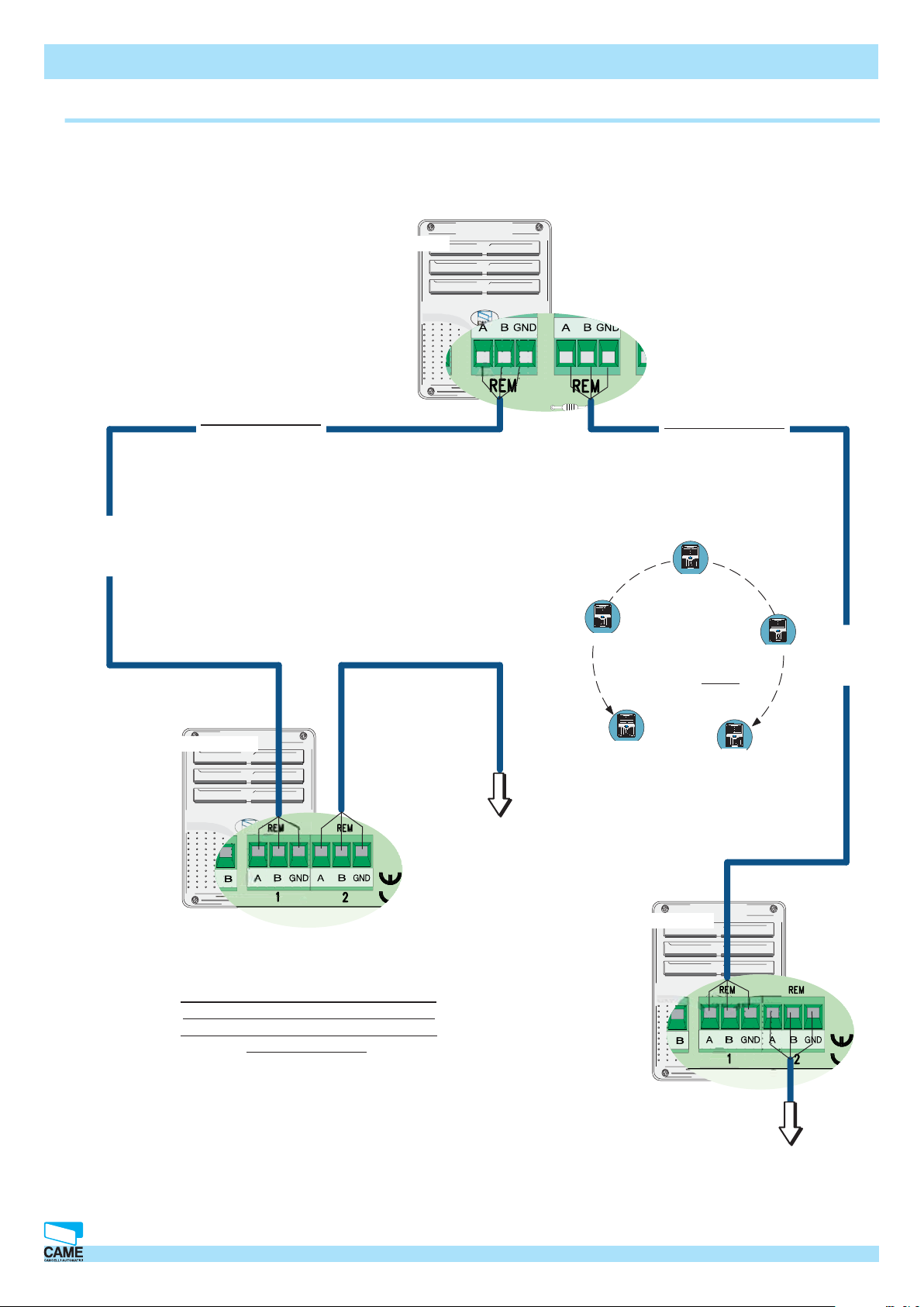
Connections for RBMP1 <--> PSR1 (PSE/PSU) e PSCA1(automatic cashier)
RBMP1
Suggested type of
non supplied cable:
Screened bi-polar
min. 2 x 0.5 mm2
Each PSR1 and PSCA1 are identifi ed by RBMP1
through a progressive number sequence,
independently of the position along the route of
the connection cable; said number, (also known as
A* line
address) must be set on the apposite dip switch on the
peripheral card (entrance and exit units and automatic
cashier)
Two line connection: the RBMP1 may be
located at any point along the connection
PSR1
RBMP1 - Installation manual
Suggested type of
non supplied cable:
Screened bi-polar
min. 2 x 0.5 mm2
cable route
RBMP1
between the fi rst and
last PSR1 or PSCA1.
The distance (meaning
the route of the
connection cable) must
be at most 1000m
PSCA1
B* line
PSR1 o PSCA1
*The PSR1s are present both in the PSE
entrance units and in the PSU exit units.
While the PSCA1 are present in the PSC
automatic cashiers.
at the subsequent* PSR1 or
PSCA1 (entrance and exit to
be plugged in at your choice on
terminals 1 or 2)
PSR1 o PSCA1
PSCA1
PSR1
at the subsequent* PSR1 or PSCA1
CAME CANCELLI AUTOMATICI S.p.A. non si assume alcuna responsabilità per errori o omissioni e si riserva di apportare continuamente le variazioni dovute al progresso tecnologico.
14 Cap.1 © CAME CANCELLI AUTOMATICI S.p.A. - 119GT33 - V2 - 09/2005 RBMPARK
Page 15
Hardware – Connections
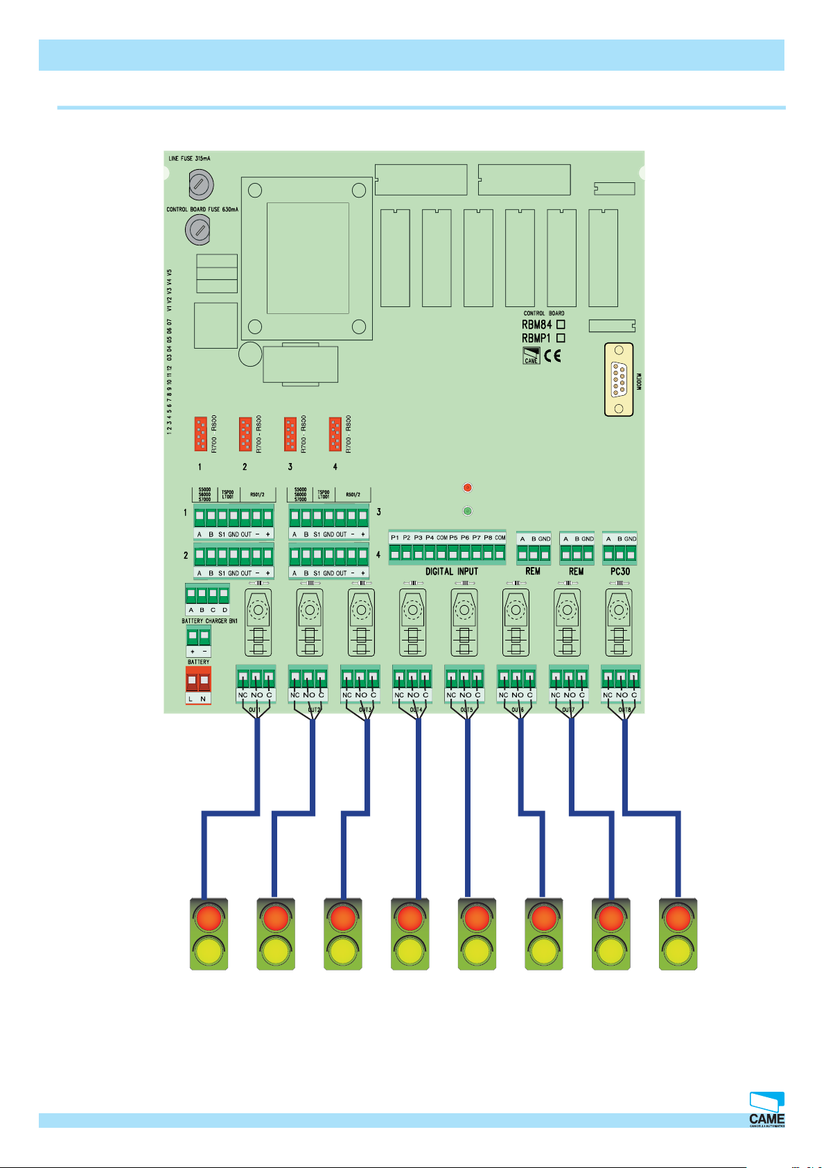
Connections for PSM4000 (RBMP1) <--> Traffi c lights
RBMP1 - Installation manual
CAME CANCELLI AUTOMATICI S.p.A. non si assume alcuna responsabilità per errori o omissioni e si riserva di apportare continuamente le variazioni dovute al progresso tecnologico.
“Partial traffi c lights” associated to different levels or sectors, up to a maximum of 16,
controlled by the software supplied.
© CAME CANCELLI AUTOMATICI S.p.A. - 119GT33 - V2 - 09/2005 RBMPARK
Cap.1
15
Page 16
Hardware – Connections
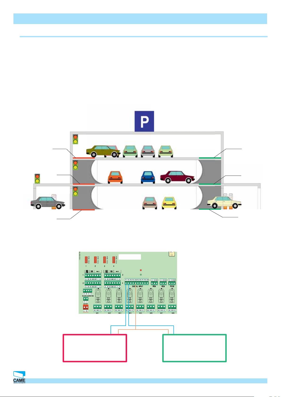
Connections for PSM4000 (RBMP1) <--> digital inputs
RBMP1 - Installation manual
The digital inputs are used for connecting the magnetic loop coils which provide immediate counts of the number
of vehicles in the car-park. These command the traffi c lights independently of the (PSE/PSU4000) entrance and
exit units.
They are widely used in multi-level car-parks, having only one entrance and one exit. Thus, they allow the exact
count of the vehicles present on each level, and the consequent number of available spaces left on each level.
Example of a multi-level car-park with loop coils for the count of vehicles on each level.
Loop Loop
Loop
PSE entrance
unit
Loop
RBMP1
Loop
PSC400 automatic
cashier and PSU
exit unit
Loop
Method of connecting the
additional loop coils to the
RBMP1, for the exact count of
vehicle on each fl oor.
CAME CANCELLI AUTOMATICI S.p.A. non si assume alcuna responsabilità per errori o omissioni e si riserva di apportare continuamente le variazioni dovute al progresso tecnologico.
Loop coil located
at the entrance
16 Cap.1 © CAME CANCELLI AUTOMATICI S.p.A. - 119GT33 - V2 - 09/2005 RBMPARK
Loop coil placed at
the exit
Page 17
Hardware – Connections
PSM4000 (RBMP1) <--> PSI16 and (PSC1) auxiliary cashiers’ connections
12V a.c. transformer included
• for 230V ac - 50÷60Hz power supply
• operating temperature range from -20 to
+50°C
PSC1
Supplied cable
(GND)
RBMP1 - Installation manual
Serial printer
(RBMP1) main control panel connection Diagram for the (PSI16)
auxiliary cashiers’ control board, and connections to the (PSC1)
auxiliary cashiers. Max distance 1000m.
CAME CANCELLI AUTOMATICI S.p.A. non si assume alcuna responsabilità per errori o omissioni e si riserva di apportare continuamente le variazioni dovute al progresso tecnologico.
(A)
(B)
Schema di collegamento tra PSC1 e PSI16
ABGND
Al PSI16
PSI16
PSI16
RBMP1
© CAME CANCELLI AUTOMATICI S.p.A. - 119GT33 - V2 - 09/2005 RBMPARK
RS232
Cap.1
17
Page 18
Hardware – Connections
CAME
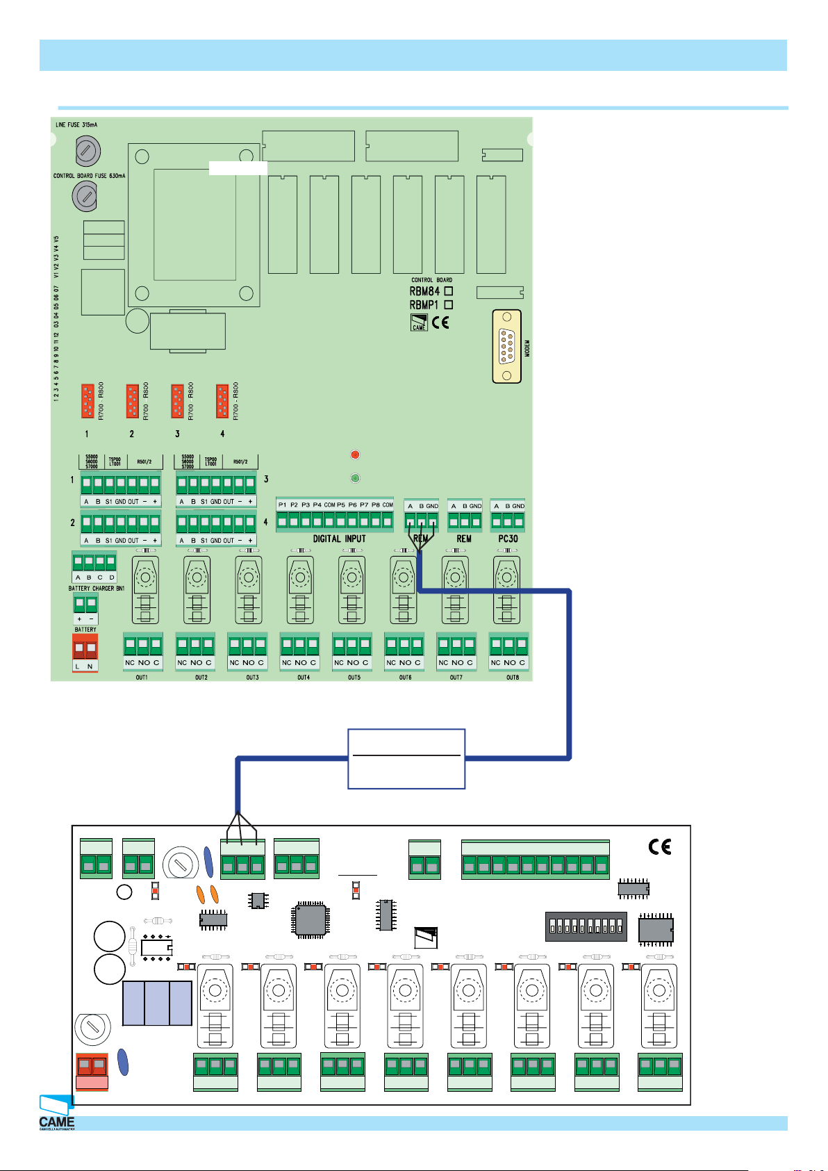
Connections for the PSM4000 (RBMP1) <--> PSIO1
RBMP1
RBMP1 - Installation manual
Suggested type of
non supplied cable:
Screened bi-polar
TAMPER
2
P1
P2 P3 P4 Com Com
P5
P6 P7 P8
TRANSFORMER TERMINAL BLOCK
230 V 0V 24V
ABGND
min. 2 x 0.5 mm
ABGND
PSIO1
ABGND
OUT 6
ON
2
1345
7
68910
ABGND
OUT 7
1 2 3 4 5 6 7 8 9 10 11 12 03 04 05 06 07 V1 V2 V3 V4 V5
ABGND
OUT 8
FUSE 630mA
CONTROL BOARD
PSIO1
ABGND
OUT 5
LINE FUSE 5A
L
N
230V AC
U2
NNC NO
ABGND
OUT 1
C NONC C NO CNC NO CNC NO CNC NO CNC NO CNC NO CNCL N
ABGND
OUT 2
ABGND
OUT 3
ABGND
OUT 4
18 Cap.1 © CAME CANCELLI AUTOMATICI S.p.A. - 119GT33 - V2 - 09/2005 RBMPARK
CAME CANCELLI AUTOMATICI S.p.A. non si assume alcuna responsabilità per errori o omissioni e si riserva di apportare continuamente le variazioni dovute al progresso tecnologico.
Page 19
Hardware – Connections
ON
ON
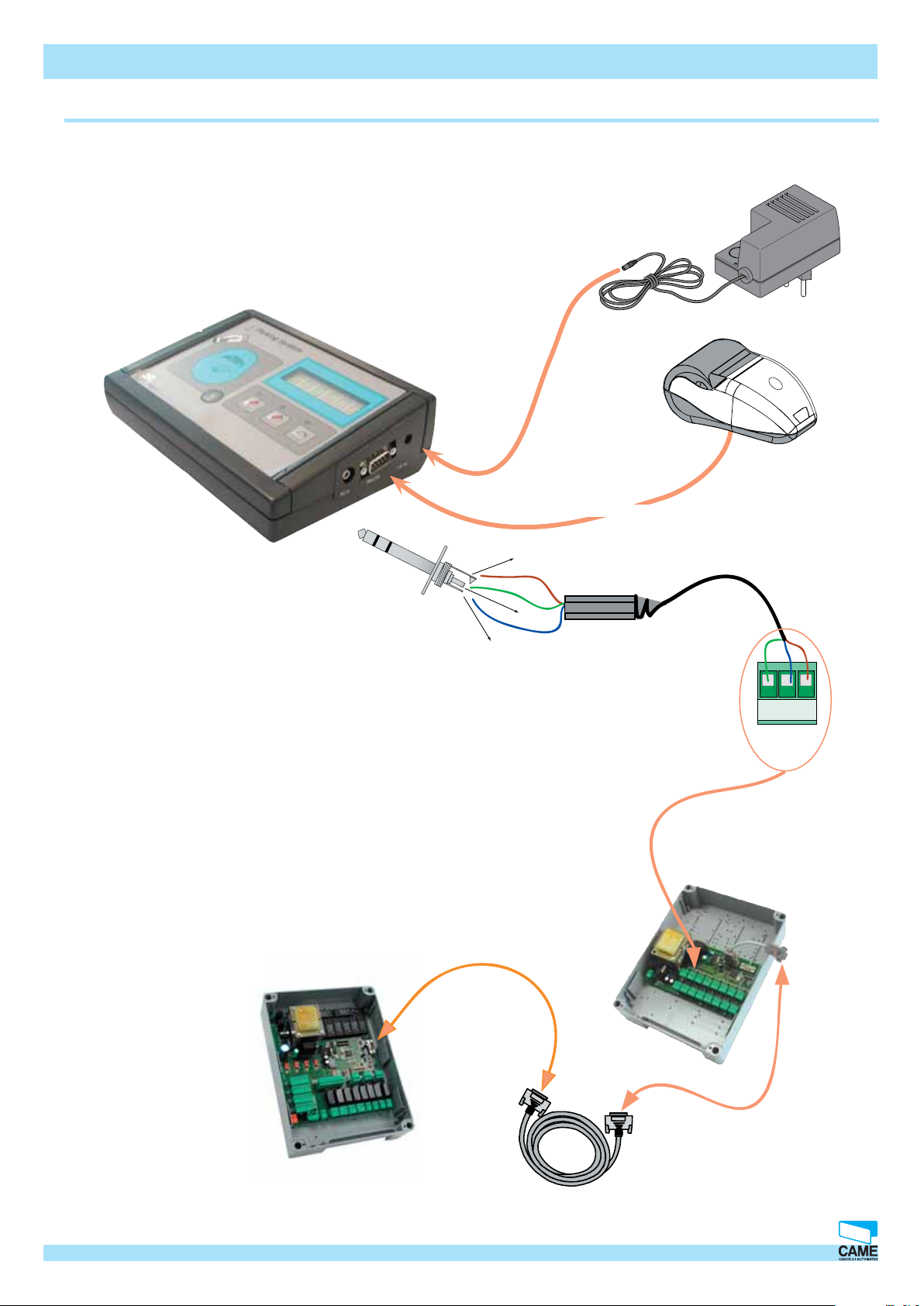
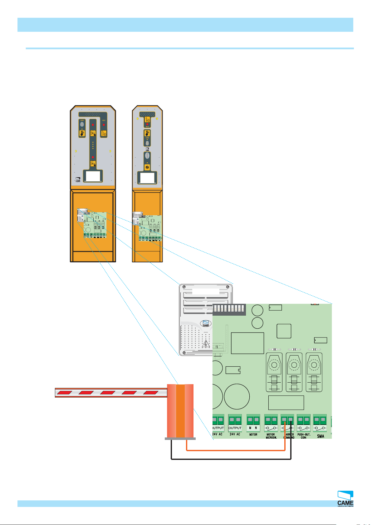
PSE/PSU4000 connections Barrier or other automation
#/).
#/).
PSR1
2
7
5
68910
34
PSR1
2
7
5
68910
34
RBMP1 - Installation manual
The connection is the same for
both the PSE and the PSU untis.
CAME CANCELLI AUTOMATICI S.p.A. non si assume alcuna responsabilità per errori o omissioni e si riserva di apportare continuamente le variazioni dovute al progresso tecnologico.
PSR1
2
7
5
68910
34
© CAME CANCELLI AUTOMATICI S.p.A. - 119GT33 - V2 - 09/2005 RBMPARK
Cap.1
19
Page 20
Hardware – Connections
ON
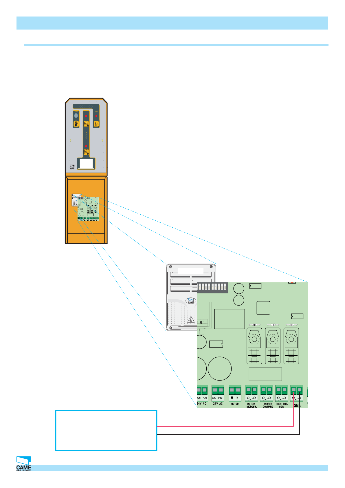
Connections for the PSE4000 <---> Loop coil
#/).
The loop coil only connects to the
PSE4000
PSR1
2
7
5
68910
34
RBMP1 - Installation manual
SMA Loop coil (vehicles)
PSR1
2
7
5
68910
34
CAME CANCELLI AUTOMATICI S.p.A. non si assume alcuna responsabilità per errori o omissioni e si riserva di apportare continuamente le variazioni dovute al progresso tecnologico.
20 Cap.1 © CAME CANCELLI AUTOMATICI S.p.A. - 119GT33 - V2 - 09/2005 RBMPARK
Page 21
Hardware – Connections
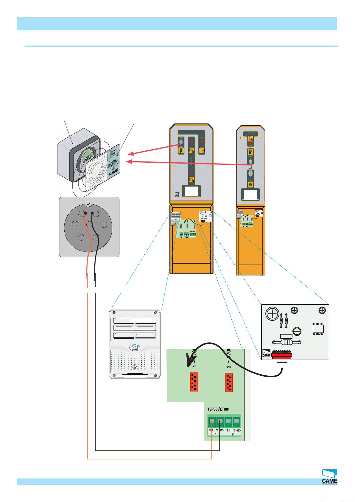
Connections for the PSE/PSU4000 <---> TSP00 transponder sensor
If the LED indicator inside the TSP00 is
GREEN this means the reader has not been set properly. If the
LED is RED this means it has been set properly.
TSP00 transponder
proximity card reader
TSP00 transponder
proximity card reader
#/).
R700
CANCELLI AUTOMATICI
RBMP1 - Installation manual
TSP00
transponder
proximity
card reader
#/).
R700
CANCELLI AUTOMATICI
RED = S1
CAME CANCELLI AUTOMATICI S.p.A. non si assume alcuna responsabilità per errori o omissioni e si riserva di apportare continuamente le variazioni dovute al progresso tecnologico.
BLACK = GND
PSR1
CANCELLI AUTOMATICI
R700
© CAME CANCELLI AUTOMATICI S.p.A. - 119GT33 - V2 - 09/2005 RBMPARK
Cap.1
21
Page 22

Hardware – Connections
DIP SWITCH
RBMP1 - Installation manual
To enable communication to take place between the RBMP1 and the PSR1 (PSE/PSU) or
rather between the RBMP1 and the PSI01 you must set the DIP Switch, by assigning one
address to each additional card. Please refer to the explanation in the following pages.
If the LED indicator is
PSE4000
blinking the communication
taking place with the
RBMP1 card is proper.
ON
2
1
34
7
5
6
10
89
1
ON
2
4
3
7
5
6
10
9
8
If the LED indicator is
PSU4000
blinking the communication
taking place with the
RBMP1 card is proper.
ON
1
2
34
5
PSIO1
ON
2
1
34
7
6
89
5
6
PSCA1
ON
10
2
1
4
3
7
6
5
10
9
8
ON
7
10
89
2
1
4
3
7
6
5
10
9
8
If the LED indicator is
blinking the communication
taking place with the
RBMP1 card is proper.
ON
2
1
34
7
5
6
10
89
ON
1
2
4
3
7
6
5
10
9
8
The DIP Switches on the various cards are usually in position n. 1
22 Cap.1 © CAME CANCELLI AUTOMATICI S.p.A. - 119GT33 - V2 - 09/2005 RBMPARK
CAME CANCELLI AUTOMATICI S.p.A. non si assume alcuna responsabilità per errori o omissioni e si riserva di apportare continuamente le variazioni dovute al progresso tecnologico.
Page 23

Hardware – Connections
List of addresses PSR1(PSE4000/PSU4000) and PSIO1
List of DIP Switches to confi gure the PSE/PSU4000 units
PSE4000
ON
2
1
7
6
5
4
3
10
9
8
RBMP1 - Installation manual
DIP SWITCH
Switch ° 12345678910N°PSIO1
OFF OFF OFF OFF OFF OFF OFF ON OFF OFF N°1
OFF OFF OFF OFF ON OFF OFF ON OFF OFF N°2
OFF OFF OFF ON OFF OFF OFF ON OFF OFF N°3
OFF OFF OFF ON ON OFF OFF
OFF OFF ON OFF OFF OFF OFF
OFF OFF ON OFF ON OFF OFF
OFF OFF ON ON OFF OFF OFF
OFF OFF ON ON ON OFF OFF
OFF ON OFF OFF OFF OFF OFF
OFF ON OFF OFF ON OFF OFF
OFF ON OFF ON OFF OFF OFF
OFF ON OFF ON ON OFF OFF
OFF ON ON OFF OFF OFF OFF
OFF ON ON OFF ON OFF OFF
OFF ON ON ON OFF OFF OFF
OFF ON ON ON ON OFF OFF
ON
ON
ON
ON
ON
ON
ON
ON
ON
ON
ON
ON
ON
OFF OFF N°4
OFF OFF N°5
OFF OFF N°6
OFF OFF N°7
OFF OFF N°8
OFF OFF N°9
OFF OFF N°10
OFF OFF N°11
OFF OFF N°12
OFF OFF N°13
OFF OFF N°14
OFF OFF N°15
OFF OFF N°16
PSU4000
Switch ° 12345678910N°PSIO1
ON OFF OFF OFF OFF OFF OFF OFF ON OFF N°1
ON OFF OFF OFF ON OFF OFF OFF ON OFF N°2
ON OFF OFF ON OFF OFF OFF OFF ON OFF N°3
ON OFF OFF ON ON OFF OFF OFF ON OFF N°4
ON OFF ON OFF OFF OFF OFF OFF ON OFF N°5
ON OFF ON OFF ON OFF OFF OFF ON OFF N°6
ON OFF ON ON OFF OFF OFF OFF ON OFF N°7
ON OFF ON ON ON OFF OFF OFF ON OFF N°8
ON ON OFF OFF OFF OFF OFF OFF ON OFF N°9
ON ON OFF OFF ON OFF OFF OFF ON OFF N°10
ON ON OFF ON OFF OFF OFF OFF ON OFF N°11
ON ON OFF ON ON OFF OFF OFF ON OFF N°12
ON ON ON OFF OFF OFF OFF OFF ON OFF N°13
ON ON ON OFF ON OFF OFF OFF ON OFF N°14
ON ON ON ON OFF OFF OFF OFF ON OFF N°15
ON ON ON ON ON OFF OFF OFF ON OFF N°16
List of DIP Switches to confi gure the PSCA1 cards
Switch ° 12345678910N°PSCA1
OFF OFF OFF OFF OFF OFF OFF OFF OFF OFF N°1
ON OFF OFF OFF OFF OFF OFF OFF OFF OFF N°2
OFF ON OFF OFF OFF OFF OFF OFF OFF OFF N°3
ON ON OFF OFF OFF OFF OFF OFF OFF OFF N°4
OFF OFF ON OFF OFF OFF OFF OFF OFF OFF N°5
ON OFF ON OFF OFF OFF OFF OFF OFF OFF N°6
OFF ON ON OFF OFF OFF OFF OFF OFF OFF N°7
ON ON ON OFF OFF OFF OFF OFF OFF OFF N°8
CAME CANCELLI AUTOMATICI S.p.A. non si assume alcuna responsabilità per errori o omissioni e si riserva di apportare continuamente le variazioni dovute al progresso tecnologico.
List of DIP Switches to confi gure the PSI01 cards
Switch ° 12345678910N°PSIO1
OFF OFF OFF OFF OFF OFF OFF OFF OFF OFF N°1
ON OFF OFF OFF OFF OFF OFF OFF OFF OFF N°2
OFF ON OFF OFF OFF OFF OFF OFF OFF OFF N°3
ON ON OFF OFF OFF OFF OFF OFF OFF OFF N°4
OFF OFF ON OFF OFF OFF OFF OFF OFF OFF N°5
ON OFF ON OFF OFF OFF OFF OFF OFF OFF N°6
OFF ON ON OFF OFF OFF OFF OFF OFF OFF N°7
ON ON ON OFF OFF OFF OFF OFF OFF OFF N°8
DIP Switch n. 10 = ON serial terminator 485
© CAME CANCELLI AUTOMATICI S.p.A. - 119GT33 - V2 - 09/2005 RBMPARK
Cap.1
23
Page 24

Hardware – Connections
Token loading procedure
1
#/).
RBMP1 - Installation manual
2
1- Unlock the lock using
the apposite keys
2-pull the PSE 4000 unit
panel outwards
3-insert the tokens
4-Close the token slot-unit
3
CAME CANCELLI AUTOMATICI S.p.A. non si assume alcuna responsabilità per errori o omissioni e si riserva di apportare continuamente le variazioni dovute al progresso tecnologico.
24 Cap.1 © CAME CANCELLI AUTOMATICI S.p.A. - 119GT33 - V2 - 09/2005 RBMPARK
Page 25

Hardware – Connections
Token unloading procedure
1
#/).
RBMP1 - Installation manual
1- Unlock the lock using
the apposite keys
2- Open the door
2
CAME CANCELLI AUTOMATICI S.p.A. non si assume alcuna responsabilità per errori o omissioni e si riserva di apportare continuamente le variazioni dovute al progresso tecnologico.
3- Remove the tokens from the
container, then close door.
© CAME CANCELLI AUTOMATICI S.p.A. - 119GT33 - V2 - 09/2005 RBMPARK
3
Cap.1
25
Page 26

Hardware – Connections
o
o
Token issuing procedure
Token issuing procedure:
RBMP1 - Installation manual
Position the vehicle on top of the SMA loop coil.
Press the red token acceptor button, and retrieve the token from the dispenser.
The token must be turned in to the cashier before picking up the vehicle, to get the cost reading
and be cleared for exit.
Please note: if the token has not been cleared for exit, when inserted into the PSU4000 unit, it
will be rejected and returned for further clearance.
Barrier or other
automation
SMA loop
PSE4000
entrance unit
Sign or traffi c light to
control access
LLiibbeerro
OOccccuuppaatto
Replacing the printer paper in the automatic cashier
To replace the printer paper in the serial printer and the automatic cashier, please refer to the
attached manuals.
RBMP1 - Installation manual
CAME CANCELLI AUTOMATICI S.p.A. non si assume alcuna responsabilità per errori o omissioni e si riserva di apportare continuamente le variazioni dovute al progresso tecnologico.
26 Cap.1 © CAME CANCELLI AUTOMATICI S.p.A. - 119GT33 - V2 - 09/2005 RBMPARK
Page 27

CHAPTER 2
RBMP1 - Software
System confi guration
INDEX
Topic page
Software installation...............................................................................................................................................2
Initial screen when program opens...................................................................................................................3
System confi guration – Main window....................................................................................................................4
PC30 confi guration................................................................................................................................................5
Selection of installed components........................................................................................................................6
Confi guration of RBMP1 digital inputs and outputs..............................................................................................7
Input and output functions.....................................................................................................................................8
Confi guring programmed exits.............................................................................................................................9
Cashier peripherals confi guration......................................................................................................................10
Setting the PSE4000..............................................................................................................................................11
Setting the PSU4000.............................................................................................................................................12
PSU4000 Functions...............................................................................................................................................13
Setting the PSIO1..................................................................................................................................................14
Setting Traffi c lights.............................................................................................................................................15
CAME CANCELLI AUTOMATICI S.p.A. non si assume alcuna responsabilità per errori o omissioni e si riserva di apportare continuamente le variazioni dovute al progresso tecnologico.
© CAME CANCELLI AUTOMATICI S.p.A. - 119GT33 - V2 - 09/2005 RBMPARK
Cap.2
1
Page 28

Software installation
Software – System configuration
Insert the CD into the apposite drive, wait for the installation window to come up on screen, and then select the
desired language. Follow the instructions.
When installation is fi nished, click on Ok
You may create a new name for
the group of programs or select one from any of the existing
groups, or, continue installation by
clicking Continue.
CAME CANCELLI AUTOMATICI S.p.A. non si assume alcuna responsabilità per errori o omissioni e si riserva di apportare continuamente le variazioni dovute al progresso tecnologico.
2 Cap.2 © CAME CANCELLI AUTOMATICI S.p.A. - 119GT33 - V2 - 09/2005 RBMPARK
Page 29

Software – System configuration
Initial screen when program opens
17
16
15
14
13
12
11
10
1 2
3
4
9
8
7
1 - PSE4000 status window
2 - PSU4000 status window
3 - Traffi c light status window
4 - System Locked/Open button
5 - System Occupancy readout window
6 - Light indicating communication up between the PC and RBMP1 (works only if all the windows
are closed and this screen is up)
7 - Window detailing last four events
8 - Password entering window
9 - Update date and time window (synchronised with those on the PC)
10 - Window to activate “Modem administration”
11 - Window to activate “System history”
CAME CANCELLI AUTOMATICI S.p.A. non si assume alcuna responsabilità per errori o omissioni e si riserva di apportare continuamente le variazioni dovute al progresso tecnologico.
12 - Window to activate “Daily history”
13 - “Occupancy management” window
14 - “System Confi guration” window
6
5
15 - “Access payment options” window
16 - “Account holder administration” window
17 - Bar for language selection, window closure and control, plus run-backup.
© CAME CANCELLI AUTOMATICI S.p.A. - 119GT33 - V2 - 09/2005 RBMPARK
Cap.2
3
Page 30

Software – System configuration
System confi guration – Main window
3
4 5 6 7
2
1
1 - PC30 confi guration window
2 - System’s graphic representation window
3 - RBMP1 Confi guration window
4 - PSE4000 Confi guration window
5 - PSU4000 confi guration window
6 - I/O card (if included) confi guration window
7 - Traffi c light (if included) confi guration window
4 Cap.2 © CAME CANCELLI AUTOMATICI S.p.A. - 119GT33 - V2 - 09/2005 RBMPARK
CAME CANCELLI AUTOMATICI S.p.A. non si assume alcuna responsabilità per errori o omissioni e si riserva di apportare continuamente le variazioni dovute al progresso tecnologico.
Page 31

PC30 confi guration
Software – System configuration
In this window select the PC entrance port to which the PC30 is connected (usually COM1)
otherwise enable connection through a modem (see chapter 7)
Warning! This operation must be carried out before starting any of the programming
or confi guration operations described below. Contrarily the software will warn you of a
COMMUNICATION ERROR, at each request to save or update.
CAME CANCELLI AUTOMATICI S.p.A. non si assume alcuna responsabilità per errori o omissioni e si riserva di apportare continuamente le variazioni dovute al progresso tecnologico.
Update
© CAME CANCELLI AUTOMATICI S.p.A. - 119GT33 - V2 - 09/2005 RBMPARK
Cap.2
5
Page 32

Software – System configuration
Selection of installed components
Using the mouse select the number of PSE4000s to
confi gure, installed in the system (up to a maximum of
16)
Using the mouse select the overall number of PSU4000
and PSR1s to confi gure, installed in the system (up to a
maximum of 16)
Using the mouse select the number of I/O cards (if
included) up to maximum of 8.
The I/O cards serve to manage any additional
elements, such as loop coils, traffi c lights,
lights, signage of sorts, etc..
Using the mouse select the number of installed traffi c
lights, up to a maximum of 16.
In the event of multiple traffi c lights do not
count the overall number of traffi c lights, becau-
se it already has a dedicated control.
Using the mouse select the number of PSCA1 Cashiers
(if included) up to a maximum number of 8.
Update
6 Cap.2 © CAME CANCELLI AUTOMATICI S.p.A. - 119GT33 - V2 - 09/2005 RBMPARK
CAME CANCELLI AUTOMATICI S.p.A. non si assume alcuna responsabilità per errori o omissioni e si riserva di apportare continuamente le variazioni dovute al progresso tecnologico.
Page 33

Software – System configuration
P1
DIGI
TAL IN PUT
P2
P3P4COM
P5
P6
P7
P8
COM
COM
P1P3P
4
P
2
O
UT1
NCNOC
O
UT2
NCNOC
O
UT3
NCNOC
R
Y
Confi guration of RBMP1 digital inputs and outputs
Clicking on this button, opens both the input and output digital function
assignation window for the RBMP1 card, as shown subsequently.
Number of digital inputs that needs setting
Assigned function
CAME CANCELLI AUTOMATICI S.p.A. non si assume alcuna responsabilità per errori o omissioni e si riserva di apportare continuamente le variazioni dovute al progresso tecnologico.
Number of relay assigned
Update
© CAME CANCELLI AUTOMATICI S.p.A. - 119GT33 - V2 - 09/2005 RBMPARK
Command
Cap.2
7
Page 34

Input and output functions
Inputs
Software – System configuration
DISABLED
TRAFFIC LIGHT N.
Outputs
CAR-PARK FULL
No function assigned
Means all of the car-park’s function are blocked.SYSTEM BLOCK
Stands for a warning signal which may be activated by button or contact.ALARM INPUT
Disabled the alarm signalRESET ALARM
A loop coil is associated to a specifi c traffi c lightENTRANCE LOOP COIL
Nothing commanded. DISABLED
Warns when all the parking spaces are full, and controls the general traffi c
light.
Activates a contact when the system is blockedSYSTEM BLOCKED
Activates a contact when the alarm is on.GENERAL ALARM
The relay is activated by passing non-cleared cards or tokens over the sensor.INTRUSION ALARM
Selects which traffi c light to controlTRAFFIC LIGHT N.
CAME CANCELLI AUTOMATICI S.p.A. non si assume alcuna responsabilità per errori o omissioni e si riserva di apportare continuamente le variazioni dovute al progresso tecnologico.
8 Cap.2 © CAME CANCELLI AUTOMATICI S.p.A. - 119GT33 - V2 - 09/2005 RBMPARK
Page 35

Software – System configuration
Confi guring programmed exits
Clicking this button, opens the setting- programmed-exits window. Programmed exits means control of one or more relays, which are used to manage
certain machinery (for example: lighting) which need to work during a predetermined time interval.
1 - Setting the relay activation-time
2 - Setting the relay-deactivation time
3 - Programs the exit (the relay that will activate)
4 - Enables the action
CAME CANCELLI AUTOMATICI S.p.A. non si assume alcuna responsabilità per errori o omissioni e si riserva di apportare continuamente le variazioni dovute al progresso tecnologico.
5 - Select the day for the action (by pressing the Copy button the settings for that particular day are assigned to all the other
days)
1
4
2
3
5
Update
© CAME CANCELLI AUTOMATICI S.p.A. - 119GT33 - V2 - 09/2005 RBMPARK
Cap.2
9
Page 36

Software – System configuration
Cashier peripherals confi guration
1
2
3
4
5
This fi eld shows the curren-
cy of the place the system is
installed.
1 - Selecting the “display installed payment” item activates the additional display for amount-readout.
2 - Input the heading to appear on all printouts.
3 - Selecting the “Enable load cashier token” item clears the token independently from the PSE4000 entrance unit.
4 - Establish the secondary payment amount for the auxiliary cashiers in the Paid 2 fi eld.
5 - Selecting the “Currency with decimals” item to move from amounts with decimals to decimal- free amounts (for e.g. from 10,30
to 1030).
Enabling the account-holders APB function, activates the Anti-Pass Back
function for all account-holders. In case of a black-out or other problems,
it is advisable to select the Synchronise function which enables proper
resetting of the system to take place (if the account-holders APB function
is selected).
CAME CANCELLI AUTOMATICI S.p.A. non si assume alcuna responsabilità per errori o omissioni e si riserva di apportare continuamente le variazioni dovute al progresso tecnologico.
Updata
10 Cap.2 © CAME CANCELLI AUTOMATICI S.p.A. - 119GT33 - V2 - 09/2005 RBMPARK
Page 37

Setting the PSE4000
Software – System configuration
Using the mouse select the PSE4000 you wish to set
(the overall number of PSE4000s has already been established).
Assign a name to the PSE4000 unit depending on requirements and structure of the car-park
If present, allows associating the PSE4000 unit to a specifi c
traffi c light
If present, it allows an auxiliary sensor to be turned on.
CAME CANCELLI AUTOMATICI S.p.A. non si assume alcuna responsabilità per errori o omissioni e si riserva di apportare continuamente le variazioni dovute al progresso tecnologico.
Update
© CAME CANCELLI AUTOMATICI S.p.A. - 119GT33 - V2 - 09/2005 RBMPARK
This command allows the cost on each single PSE4000 to
be changed in percentage terms. For example: in car-park
with indoor and outdoor areas, you can assign a higher cost
to the indoor areas.
Cap.2
11
Page 38

Setting the PSU4000
Software – System configuration
Using the mouse select the PSU4000 you want to set
(the overall number of PSU4000s has already been
inputed)
If present, it allows an auxiliary sensor to be
turned on.
Defi nes the function of the PSU4000 exit unit
If present, it allows the PSU4000 unit to be assigned to a specifi c traffi c light.
Provide a name for the PSE4000 unit depending
on the requirements of the parking facility
CAME CANCELLI AUTOMATICI S.p.A. non si assume alcuna responsabilità per errori o omissioni e si riserva di apportare continuamente le variazioni dovute al progresso tecnologico.
Update
12 Cap.2 © CAME CANCELLI AUTOMATICI S.p.A. - 119GT33 - V2 - 09/2005 RBMPARK
Page 39

PSU4000 Functions
Software – System configuration
PSU4000
ACCOUNT-HOLDERS’
ENTRANCE
EXIT
AUTOMATIC PAYMENT
LOAD TOKEN
ACCOUNT HOLDER
TRANSIT
Standard function of an exit unit
This unit is only used with an entrance sensor for account-holders
This unit is only used with an exit sensor for account holdersACCOUNT HOLDERS’
By running the token over the sensor, the latter is automatically cleared for exit
without having to go through the PC.
By running through the not-yet-cleared token, the latter is loaded within the
system.
Allows the entrance and exit of account-holders, for instance from a pedestrian
area, without debiting any prepaid credit.
CAME CANCELLI AUTOMATICI S.p.A. non si assume alcuna responsabilità per errori o omissioni e si riserva di apportare continuamente le variazioni dovute al progresso tecnologico.
© CAME CANCELLI AUTOMATICI S.p.A. - 119GT33 - V2 - 09/2005 RBMPARK
Cap.2
13
Page 40

Setting the PSIO1
Software – System configuration
Select which I/O card you wish to set
Assigns a certain function to a digital input number (Block system, Alarm entrance, etc.) which in
turn excites an exit relay. (please go to page 8 for
the functions)
Set the exit relay number that needs to activate,
along with the function assigned to it.
(please go to page 8 for the functions)
CAME CANCELLI AUTOMATICI S.p.A. non si assume alcuna responsabilità per errori o omissioni e si riserva di apportare continuamente le variazioni dovute al progresso tecnologico.
Update
14 Cap.2 © CAME CANCELLI AUTOMATICI S.p.A. - 119GT33 - V2 - 09/2005 RBMPARK
Page 41

Setting Traffi c lights
Software – System configuration
Select the traffi c light that needs setting
CAME CANCELLI AUTOMATICI S.p.A. non si assume alcuna responsabilità per errori o omissioni e si riserva di apportare continuamente le variazioni dovute al progresso tecnologico.
In the fi rst fi eld set the number of vehicles asso-
ciated to this traffi c light; in the fi eld below set the
number of occupied or reserved parking places.
By selecting “Employ Loop Coil” the increase or
decrease of vehicles will take place through the
action of the magnetic loop coil.
Update
© CAME CANCELLI AUTOMATICI S.p.A. - 119GT33 - V2 - 09/2005 RBMPARK
Cap.2
15
Page 42

CHAPTER 3
RBMP1 - Software
Accesses and methods of payment
INDEX
Topic page
General Occasional................................................................................................................................................2
Time frames.............................................................................................................................................................3
Special Days ...........................................................................................................................................................4
Payments...............................................................................................................................................................6
Options.....................................................................................................................................................................7
For occasional (Time frames, Single Cost)................................................................................................8
For occasionals (Progressive Cost, Fixed Daily Cost)..............................................................................9
For occasionals (Free time frame, Applies the fi xed daily cost after 24 hours have elapsed)...............10
For account holders (Time frames, Single Cost).....................................................................................11
For account holders (Fixed Daily Cost, Roundings Off ).......................................................................12
CAME CANCELLI AUTOMATICI S.p.A. non si assume alcuna responsabilità per errori o omissioni e si riserva di apportare continuamente le variazioni dovute al progresso tecnologico.
© CAME CANCELLI AUTOMATICI S.p.A. - 119GT33 - V2 - 09/2005 RBMPARK
Cap.3
1
Page 43

Software-Accesses and methods of payment
General Occasional
RBPARK Software ~ Installation manual
Clicking on this button opens the accesses and payment- methods setting window.
“General occasional” means the system’s temporary settings, for occasional customers that use tokens,
that is, unregistered non-cardholders.
1
2
4
5
3
EURO
1 - Set day
2 - System opening and closing times
3 - Possible occasional customers entrance and exit times
4 - Vehicle exit time (between payment and exiting the car-park)
6 - Select default vehicle retrieval time
7 - Free time interval (when vehicle enters and exits
without parking)
5 - Second vehicle exit time
6
7
Warning! For the changes to be valid, you need to update after each series of operations.
Update
2 © CAME CANCELLI AUTOMATICI S.p.A. - 119GT33 - V2 - 09/2005 RBMPARK
CAME CANCELLI AUTOMATICI S.p.A. non si assume alcuna responsabilità per errori o omissioni e si riserva di apportare continuamente le variazioni dovute al progresso tecnologico.
Cap.3
Page 44

Software-Accesses and methods of payment
Time frames
RBPARK Software ~ Installation manual
Warning! The time frames must absolutely be set when selecting “Use time frame” in the payment
window..
1
*
2
3
4
EURO
Please note: you can set up to a maximum of 4 time frames per day
1 - Day to be set (to apply the same settings for all the days press Copy)
2 - Select and visualise the time frame
3 - Frame box for setting the time frame (to apply the same settings for all the days press Copy)
4 - Free time frame setting table
CAME CANCELLI AUTOMATICI S.p.A. non si assume alcuna responsabilità per errori o omissioni e si riserva di apportare continuamente le variazioni dovute al progresso tecnologico.
Please note: free time frame means a time interval in which parking costs are not applied.
Warning! For the changes to be valid, you need to update after each series of operations.
Update
Cap.3 © CAME CANCELLI AUTOMATICI S.p.A. - 119GT33 - V2 - 09/2005 RBMPARK
3
Page 45

Software-Accesses and methods of payment
Special Days
Special days means holidays such as Christmas Day, Mid-Summer’s Day, as well as free days when
the car-park is not operational (or unmanned).
Holidays:
On holidays access is granted only to account holders.
1
RBPARK Software ~ Installation manual
2
1 - Provides a visual display of Holidays
2 - Box frame to set the holidays
EURO
CAME CANCELLI AUTOMATICI S.p.A. non si assume alcuna responsabilità per errori o omissioni e si riserva di apportare continuamente le variazioni dovute al progresso tecnologico.
Update
4 © CAME CANCELLI AUTOMATICI S.p.A. - 119GT33 - V2 - 09/2005 RBMPARK
Cap.3
Page 46

Software-Accesses and methods of payment
Special days
Free Days:
In free days, free entrance and exit is granted to all customers provided that this take place during the
established time frame.
RBPARK Software ~ Installation manual
1
2
1 - Provides a visual display of free days
2 - Box frame to set the free days
CAME CANCELLI AUTOMATICI S.p.A. non si assume alcuna responsabilità per errori o omissioni e si riserva di apportare continuamente le variazioni dovute al progresso tecnologico.
EURO
Update
Cap.3 © CAME CANCELLI AUTOMATICI S.p.A. - 119GT33 - V2 - 09/2005 RBMPARK
5
Page 47

Software-Accesses and methods of payment
Payments
RBPARK Software ~ Installation manual
This is the main window to set the payment methods for occasional customers and account-holders with prepaid
cards (time cards are not valid here)
This frame box shows all the payment methods available for occasional customers (tokens)
EURO
This frame box shows the payment
method settings for account holders
(prepaid cards)
CAME CANCELLI AUTOMATICI S.p.A. non si assume alcuna responsabilità per errori o omissioni e si riserva di apportare continuamente le variazioni dovute al progresso tecnologico.
6 © CAME CANCELLI AUTOMATICI S.p.A. - 119GT33 - V2 - 09/2005 RBMPARK
Cap.3
Page 48

Software-Accesses and methods of payment
Options
RBPARK Software ~ Installation manual
In this window you can select whether to enable the VAT amount separately from the total cost.
CAME CANCELLI AUTOMATICI S.p.A. non si assume alcuna responsabilità per errori o omissioni e si riserva di apportare continuamente le variazioni dovute al progresso tecnologico.
Update
EURO
Cap.3 © CAME CANCELLI AUTOMATICI S.p.A. - 119GT33 - V2 - 09/2005 RBMPARK
7
Page 49

Software-Accesses and methods of payment
Payments
Occasionals/Time frames:
RBPARK Software ~ Installation manual
To enable the time frames select “Use time
frames” (for settings see page 3)
Occasionals/Single Cost:
Setting the Single Cost, also sets:
- the time frame;
- the assigned cost;
- the crediting method.
Normally the credit is detracted by compu-
ting the actual staying time; if, contrarily, the
“Compute-by-Time- Units” item is selected,
then the credit is detracted by calculating
the time intervals of stay (fractions of time
are considered as units).
For example, as the shown in the diagram,
if the stay amounts to 20 minutes, in the fi rst
instance (actual time) a cost of 3(€,$,£,¥ ...)
/ 15’ x 20’ = 4 (€,$,£,¥ ...) is computed;
in the second instance (time units) the time
interval is computed twice, thus the cost will
be of 6 (€,$,£,¥ ...).
Update
8 © CAME CANCELLI AUTOMATICI S.p.A. - 119GT33 - V2 - 09/2005 RBMPARK
CAME CANCELLI AUTOMATICI S.p.A. non si assume alcuna responsabilità per errori o omissioni e si riserva di apportare continuamente le variazioni dovute al progresso tecnologico.
Cap.3
Page 50

Software-Accesses and methods of payment
Payments
Occasionals/Progressive Cost:
RBPARK Software ~ Installation manual
The progressive cost payment method allows
two different price brackets. (It does not take
into account the time interval)
Occasionals/Fixed Daily Cost:
CAME CANCELLI AUTOMATICI S.p.A. non si assume alcuna responsabilità per errori o omissioni e si riserva di apportare continuamente le variazioni dovute al progresso tecnologico.
The fi xed daily cost payment method requi-
res a rate to be set, which is applied to each
access on a daily-basis (from 00:01 to 24:00).
For example, if entering on the afternoon of
a particular day, and exiting the morning after
the rate is applied twice.
Update
Cap.3 © CAME CANCELLI AUTOMATICI S.p.A. - 119GT33 - V2 - 09/2005 RBMPARK
9
Page 51

Software-Accesses and methods of payment
Payments
Occasionals/Free time frame:
Occasionals/Applies the fi xed daily cost after 24 hours have elapsed:
RBPARK Software ~ Installation manual
Selecting this function, sets a maximum
expense fi gure; once this is reached no other
increment will take effect.
Selecting this fucntion, applies a fi xed daily
cost;
And then selecting “Apply fi xed daily cost” af-
ter 24 hours, then a fi xed rate will be applied
after 24 hours of parking.
Occasionals/Maximum cost
Occasionals/rounding off:
Selecting this function, sets a maximum
expense fi gure; once this is reached no other
increment will take effect.
In this window you can set the required rounding off for currencies with decimals (€,$,£,¥
...), and will be applied to all payment methods
CAME CANCELLI AUTOMATICI S.p.A. non si assume alcuna responsabilità per errori o omissioni e si riserva di apportare continuamente le variazioni dovute al progresso tecnologico.
Update
10 © CAME CANCELLI AUTOMATICI S.p.A. - 119GT33 - V2 - 09/2005 RBMPARK
Cap.3
Page 52

Software-Accesses and methods of payment
Payments
Account-holders/Time Frames:
RBPARK Software ~ Installation manual
To enable the time frames,
select “Use time frames” (see
settings on page 3)
Account holders/Single cost:
Setting the Single Cost, also sets:
- the time frame;
- the assigned cost;
- the crediting method.
Normally the credit is detracted by computing the actual staying time; if, contrarily, the
“Compute-by-Time- Units” item is selected,
then the credit is detracted by calculating
the time intervals of stay (fractions of time
are considered as units).
For example, as the shown in the diagram,
if the stay amounts to 20 minutes, in the fi rst
instance (actual time) a cost of 3(€,$,£,¥ ...)
/ 15’ x 20’ = 4 (€,$,£,¥ ...) is computed;
in the second instance (time units) the time
interval is computed twice, thus the cost will
be of 6 (€,$,£,¥ ...).
CAME CANCELLI AUTOMATICI S.p.A. non si assume alcuna responsabilità per errori o omissioni e si riserva di apportare continuamente le variazioni dovute al progresso tecnologico.
Update
Cap.3 © CAME CANCELLI AUTOMATICI S.p.A. - 119GT33 - V2 - 09/2005 RBMPARK
11
Page 53

Software-Accesses and methods of payment
Payments
Account Holders/Fixed Daily Cost:
RBPARK Software ~ Installation manual
The fi xed daily cost payment method requi-
res a rate to be set, which is applied to each
access on a daily-basis (from 00:01 to 24:00).
For example, if entering on the afternoon of
a particular day, and exiting the morning after
the rate is applied twice.
Account Holders/ Roundings Off:
In this window you can set the required rounding off for currencies with decimals (€,$,£,¥
...), and will be applied to all payment methods
Account holders/maximum cost:
Selecting this function, sets a maximum
expense fi gure; once this is reached no other
increment will take effect.
Update
12 © CAME CANCELLI AUTOMATICI S.p.A. - 119GT33 - V2 - 09/2005 RBMPARK
CAME CANCELLI AUTOMATICI S.p.A. non si assume alcuna responsabilità per errori o omissioni e si riserva di apportare continuamente le variazioni dovute al progresso tecnologico.
Cap.3
Page 54

CAPITOLO 4
RBMP1 - Software
Gestione abbonati
SOMMARIO
argomento pagina
Personali................................................................................................................................................2
Accesso...................................................................................................................................................................3
Stato.......................................................................................................................................................................4
CAME CANCELLI AUTOMATICI S.p.A. non si assume alcuna responsabilità per errori o omissioni e si riserva di apportare continuamente le variazioni dovute al progresso tecnologico.
© CAME CANCELLI AUTOMATICI S.p.A. - 119GT33 - V2 - 09/2005 RBMPARK
Cap.4
1
Page 55

Software-Gestione abbonati
Personali
1
Software RBPARK ~ Manuale d-uso
Cliccando su questo pulsante, si apre la fi nestra per la “Gestione degli Abbonati”
Cliccando su questo pulsante, si attiva la schermata per l’inserimento dell’abbonato.
3
2
1 - Finestra dati possessore tessera
2 - Pulsanti di comando
3 - Finestra lista utenti
2
Cap.4
© CAME CANCELLI AUTOMATICI S.p.A. - 119GT33 - V2 - 09/2005 RBMPARK
CAME CANCELLI AUTOMATICI S.p.A. non si assume alcuna responsabilità per errori o omissioni e si riserva di apportare continuamente le variazioni dovute al progresso tecnologico.
Page 56

Software-Gestione abbonati
Accesso
1
2
3
4
Software RBPARK ~ Manuale d-uso
1 - Box per la lettura codice tessere e relativa associazione all’abbonato (si possono associare fi no a nove
tessere ad ogni singolo utente)
2 - Visualizzazione e possibilità di selezione delle fasce orarie
3 - Selezione della tipologia contratto e durata dello stesso
4 - Box per la gestione del credito nella tessera
N.B.: Se le fasce orarie non coprono l’intervallo di tempo della sosta verrà utilizzato in automatico il
costo fi sso giornaliero.
CAME CANCELLI AUTOMATICI S.p.A. non si assume alcuna responsabilità per errori o omissioni e si riserva di apportare continuamente le variazioni dovute al progresso tecnologico.
Se selezioniamo il contratto Normale basterà decidere il tempo di attivazione, senza impostare tipologie
di pagamenti.
© CAME CANCELLI AUTOMATICI S.p.A. - 119GT33 - V2 - 09/2005 RBMPARK
Cap.4
3
Page 57

Software-Gestione abbonati
Stato
Software RBPARK ~ Manuale d-uso
4
Questa fi nestra mette in evidenza informa-
zioni del singolo utente, utili per il normale
controllo dell’impianto.
Cap.4
© CAME CANCELLI AUTOMATICI S.p.A. - 119GT33 - V2 - 09/2005 RBMPARK
CAME CANCELLI AUTOMATICI S.p.A. non si assume alcuna responsabilità per errori o omissioni e si riserva di apportare continuamente le variazioni dovute al progresso tecnologico.
Page 58

CHAPTER 5
RBMP1 - Software
System activity read out
INDEX
Topic page
Occupancy................................................................................................................................................2
Daily.........................................................................................................................................................................3
Historical data.........................................................................................................................................................6
CAME CANCELLI AUTOMATICI S.p.A. non si assume alcuna responsabilità per errori o omissioni e si riserva di apportare continuamente le variazioni dovute al progresso tecnologico.
© CAME CANCELLI AUTOMATICI S.p.A. - 119GT33 - V2 - 09/2005 RBMPARK
Cap.5
1
Page 59

Software-System activity read out
Occupancy
1
2
Software RBPARK ~ Operating Manual
Clicking this button opens the “Occupancy” window which shows the customers in
the car-park (it does not come up when the car-park is empty).
4
3
1 - Occasional customer display window.
2 - Forced removal of customer window
3 - Occupancy update display button
4 - Window close button.
1
2
3
1 - Account-holding customers display window.
2 - Forced removal of customer window.
2
Cap.5
4
3 - Occupancy update display button.
4 - Window close button.
© CAME CANCELLI AUTOMATICI S.p.A. - 119GT33 - V2 - 09/2005 RBMPARK
CAME CANCELLI AUTOMATICI S.p.A. non si assume alcuna responsabilità per errori o omissioni e si riserva di apportare continuamente le variazioni dovute al progresso tecnologico.
Page 60
Software-System activity read out
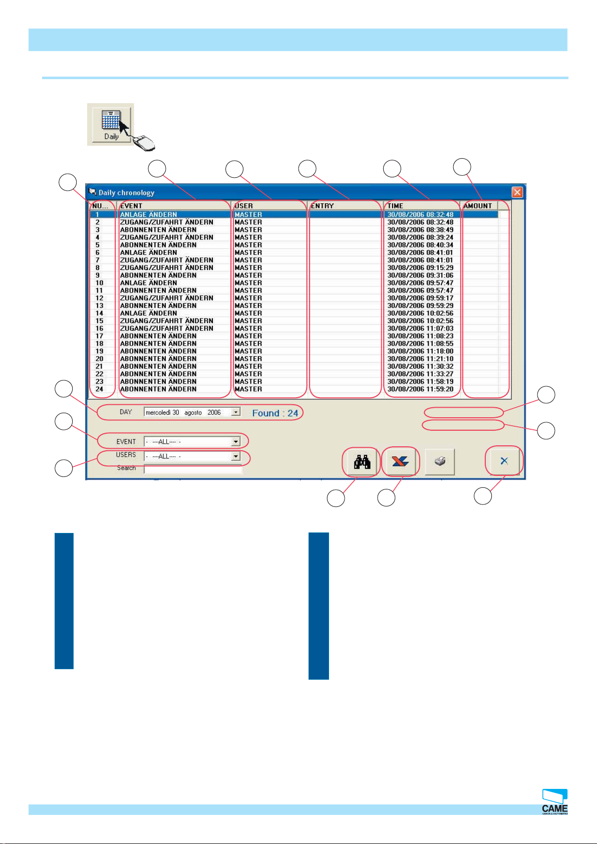
Daily
Software RBPARK ~ Operating Manual
Clicking this button, opens the “Daily historical” window.
2
3
4 5
6
1
14
13
12
1 - Event number column
2 - Event description event
3 - Colonna di visualizzazione utente
4 - Customer display column
5 - Column displaying the date and time of the event
6 - Column showing any paid amounts
CAME CANCELLI AUTOMATICI S.p.A. non si assume alcuna responsabilità per errori o omissioni e si riserva di apportare continuamente le variazioni dovute al progresso tecnologico.
7 - Amount paid by occasional customers.
11
8 - Amount paid for recharging cards
9 - “Close” button
10 - “Print” button
11 - “New search” button
12 - Customer search frame box
13 - Event search frame box
14 - Day search frame box
10
7
8
9
© CAME CANCELLI AUTOMATICI S.p.A. - 119GT33 - V2 - 09/2005 RBMPARK
Cap.5
3
Page 61

Software-System activity read out
Daily
Events
TRANCE
ERROR: APB
ERROR: CONTRACT
ERROR: TIME FRAME
ERROR: BLOCKED
Software RBPARK ~ Operating Manual
Account holder entrance means access by card-holder (registered customer)ACCOUNT HOLDER EN-
Account holder means exit by card-holder (registered user)ACCOUNT HOLDER EXIT
The APB function (Anti-Pass Back) precludes the use of a card by another
customer when the original customer is still present in the facility
Contract errors warn of attempted accesses by customers not cleared for entrance at that particular moment.
Credit errors warn of attempted accesses by customers with insuffi cient credit.ERROR: CREDIT
Time frame errors warn of attempted accesses by users not cleared for that
particular time frame.
This means access has been attempted using an invalid card. A TTEMPTED ACCESS
The blocked error warns of an attempted access, when system is blocked,
either by occasional customers or account-holders.
EXIT
KEN
TERM.
MODIFY SYSTEM
MODIFY ACCESS
New entrance means a new occasional entrance has taken placeNEW ENTRACE
This item warns of the exit from the car-park of either an occasional customer
or card holder.
This shows payment made in manual mode (manned cashier).PAYMENT: MANUAL
This payment made in automatic mode (automatic cashier).P A YMENT: AUTO
Shows manual opening of the entrance barrier.MANUAL OPENING TO-
Shows the manual opening of the exit barrier.MANUAL OPENING
Shows manual loading of token (token is cleared).LOAD TOKEN
Shows recharging of card.RECHARGE ACCOUNT
Shows a change in the setting of the system (displayed only after password is
inserted)
Shows a change in the system’s mode of access (displayed only after password is inserted)
CAME CANCELLI AUTOMATICI S.p.A. non si assume alcuna responsabilità per errori o omissioni e si riserva di apportare continuamente le variazioni dovute al progresso tecnologico.
MODIFY ACCOUNT HOLDERS
SING
AUTOMATICA
4
Shows a change in the handling of account-holders (displayed only after password is inserted)
Shows the passing of an account holder.ACCOUNT HOLDER PAS-
Shows payment made at an automatic cashier by an occasional customerPAGAMENTO CASSA
Shows a recharge made at an automatic cashier by an account-holder.AUTOMATIC RECHARGE
Cap.5
© CAME CANCELLI AUTOMATICI S.p.A. - 119GT33 - V2 - 09/2005 RBMPARK
Page 62

Software-System activity read out
Daily
COUNT HOLDER
Customers
DERS
CUSTOMER NAME
Software RBPARK ~ Operating Manual
Shows the opening of a work shift by an operator.OPEN SHIFT
Shows the closing of a work shift by an operator.CLOSE SHIFT
Shows removal of an occasional customer by an operator. REMOVE TOKEN
Shows manual exit (made by operator) of an account holder.MANUAL EXIT OF AC-
Search is run only on occasional customersONLY OCCASIONALS
Search is run only on account-holdersONL Y ACCOUNT HOL-
Running a search for a single registered customer is possible. This can display
historical data.
OPERATOR NAME
Running a search for a single operator is possible. This can display date on
changes made on the system or other parameters of the car-park (displayed
only after password is inserted)
By selecting among EVENTS and CUSTOMERS you can run an advanced search to remove useless
data and quickly fi nd the required information.
To respect privacy laws: enable the system password so that all account holder traffi c may only be
viewed the system administrator (holding the master password).
CAME CANCELLI AUTOMATICI S.p.A. non si assume alcuna responsabilità per errori o omissioni e si riserva di apportare continuamente le variazioni dovute al progresso tecnologico.
© CAME CANCELLI AUTOMATICI S.p.A. - 119GT33 - V2 - 09/2005 RBMPARK
Cap.5
5
Page 63

Software-System activity read out
Historical data
Clicking this button opens the “Historical Data???” window.
The difference between Daily and Historical is the time interval of the search. The daily
search looks at data on one particular day, while the historical data allows the time interval in
which to search to be extended.
1 2 3 4 5
Software RBPARK ~ Operating Manual
6
18
17
16
15
14
13
1 - Event number column
2 - Event description column
3 - Customer display column
4 - Column displaying the threshold involved in the event
5 - Column displaying the date and time of the event
6 - Column showing any paid amounts
7 - Amount paid by occasional customers.
12
10 - “Print” button
11 - Export-data-to-Excel button
12 - “New search” button
13 - Number of events found
14 - Frame box for name search
15 - User reload frame box
16 - Search Events Frame box
11
10
7
8
9
CAME CANCELLI AUTOMATICI S.p.A. non si assume alcuna responsabilità per errori o omissioni e si riserva di apportare continuamente le variazioni dovute al progresso tecnologico.
8 - Amount paid for recharging cards
9 - “Close” button
The EVENTS and ACCOUNT HOLDERS items are the same as those described in pages 4 and 5.
6
Cap.5
© CAME CANCELLI AUTOMATICI S.p.A. - 119GT33 - V2 - 09/2005 RBMPARK
17 - Select end-search-ate Frame box
18 - Select begin-search-date Frame Box
Page 64

CHAPTER 6
RBMP1 - Software
Password Management
INDEX
Topic page
Administrator password........................................................................................................................................2
Operators password...............................................................................................................................................3
CAME CANCELLI AUTOMATICI S.p.A. non si assume alcuna responsabilità per errori o omissioni e si riserva di apportare continuamente le variazioni dovute al progresso tecnologico.
© CAME CANCELLI AUTOMATICI S.p.A. - 119GT33 - V2 - 09/2005 RBMPARK
Cap.6
1
Page 65

Software-System activity read out
Administrator password
Clicking this button, opens the password- insert window
Once the change are applied the
following message will appear
RBPARK Software ~ Installation manual
Insert the required password in the “NEW” fi eld;
repeat this in the “CONFIRM” fi eld to check that
there aren’t any discrepancies. This will be the
system administrator’s password, that is, the person who will manage the operators.
Click OK to activate changes
When the password is enabled the key turns red.
Please note: the program accepts a maximum of 8 numerical and alphabetical characters
Operators’ passwords
Clicking the red key icon opens the change-the-password window. Here you can
set passwords for operators or change that of the administrator.
The Administrator’s password is required to
make any change
To disable or change the main password select
the checkbox
Clicking this button opens the insert-operatorpassword window
CAME CANCELLI AUTOMATICI S.p.A. non si assume alcuna responsabilità per errori o omissioni e si riserva di apportare continuamente le variazioni dovute al progresso tecnologico.
2
Cap.6
© CAME CANCELLI AUTOMATICI S.p.A. - 119GT33 - V2 - 09/2005 RBMPARK
Page 66

Software-System activity read out
Operators password
1
2
RBPARK Software ~ Installation manual
9
3
1 - Operators password activity summary window
2 - Select operator status
3 - Button to remove operators
4 - Select operator authorisations
5 - Operator name input fi eld
6 - Save button
7 - Apply button
8 - Close button
CAME CANCELLI AUTOMATICI S.p.A. non si assume alcuna responsabilità per errori o omissioni e si riserva di apportare continuamente le variazioni dovute al progresso tecnologico.
9 - Operator password input fi eld
4 5 6 7 8
© CAME CANCELLI AUTOMATICI S.p.A. - 119GT33 - V2 - 09/2005 RBMPARK
Cap.6
3
Page 67

CHAPTER 7
RBMP1 - Software
Modem
INDEX
Topic page
Connecting from a remote PC...............................................................................................................................2
Remote connection window.....................................................................................................................................4
CAME CANCELLI AUTOMATICI S.p.A. non si assume alcuna responsabilità per errori o omissioni e si riserva di apportare continuamente le variazioni dovute al progresso tecnologico.
© CAME CANCELLI AUTOMATICI S.p.A. - 119GT33 - V2 - 09/2005 RBMPARK
Cap.7
1
Page 68

Modem-administration software
Connecting from a remote PC
RBPARK Software ~ Installation manual
Please note: the following HATES standard modems can be used: GSM and PSTN.
The communication takes place among the PC, the transmitting modem, the receiving modem and the RBMPARK; when
connection is up, you can change any parameter, and read any information. However, non new account-holders may be
created.
1-Select the system confi guration
2-Enter the PC30 window and select MODEM- communication as shown in
the diagram…the two-telephone-icon will appear once the MODEM-communication is selected. Save changes.
…after the modem connection is selected, the two-phone icon
will appear. Save changes…
Update
2
Cap.7
© CAME CANCELLI AUTOMATICI S.p.A. - 119GT33 - V2 - 09/2005 RBMPARK
CAME CANCELLI AUTOMATICI S.p.A. non si assume alcuna responsabilità per errori o omissioni e si riserva di apportare continuamente le variazioni dovute al progresso tecnologico.
Page 69

Modem-administration software
Connecting from a remote PC
1-Select remote connection
RBPARK Software ~ Installation manual
2- Click on fi nd mo-
dem button.
When modem is found,
CAME CANCELLI AUTOMATICI S.p.A. non si assume alcuna responsabilità per errori o omissioni e si riserva di apportare continuamente le variazioni dovute al progresso tecnologico.
the readout shows the
phrase Modem found as
well as on which port it
is connected.
5- Launch the connection..
4-Add the name to the list by clicking on the arrow.
3
3-Add both system reference name as well as the
number to be dialled for connection.
© CAME CANCELLI AUTOMATICI S.p.A. - 119GT33 - V2 - 09/2005 RBMPARK
Cap.7
3
Page 70

Modem-administration software
Remote connection window
12
11
10
1
32
4
13
6 5789
1 - Address Book display window
2 - Disconnect button
3 - Connect button
4 - Installed modem detection button
5 - Exit button
6 - Selection to activate system history readout
7 - Remove user button
8 - Cancel activity button
9 - Save button
10- Field for adding telephone number.
11- Field for adding name of remote modem
12- Name and number input button
13- Select connection speed
Once the remote connection window is up, you need to:
- assign a name and number to the modem that will be called
- have the system detect the modem (the one connected to your PC)
- save changes
- Initiate the call by pressing on the Connect button
- once the system is connected you may shut the remote connection window, and use the RBMpark.
CAME CANCELLI AUTOMATICI S.p.A. non si assume alcuna responsabilità per errori o omissioni e si riserva di apportare continuamente le variazioni dovute al progresso tecnologico.
4
Cap.7
© CAME CANCELLI AUTOMATICI S.p.A. - 119GT33 - V2 - 09/2005 RBMPARK
 Loading...