

Page 1

S E C T I O N 1
RBM84 - hardware
CONTENTS
subject page
RBM84 Motherboard - description
REM Motherboard - description ........................................................................................ 3
PC30 - description ........................................................................................................... 4
General layout RBM84 system ......................................................................................... 5
RBM84 Connection <----> PC30 <----> Personal Computer .................................................. 6
RBM84 Connection <----> REM (one section) ...................................................................... 7
RBM84 Connection <----> REM (two sections) ...................................................................... 8
RBM84/REM Connection <---> sensor: REMOTE CONTROL .................................................. 9
RBM84/REM Connection <---> Keyboard selector, series S5000 ......................................... 10
RBM84/REM Connection <---> Keyboard selector, series S6000/S7000 ............................... 11
RBM84/REM Connection <---> Sensor transponder for proximity devices ............................ 12
RBM84/REM Connection <---> Sensor for magnetic swipe cards ......................................... 13
RBM84/REM Connection <---> Digital entrance contacts .................................................... 14
List of REM addresses ................................................................................................. 15
2
Page 2
FUSE 630m A
CONTROL BOARD
PSIO1
TRANSFORMER TERMINAL BLOCK
LINE FUSE 5A
CAME
U2
REM
REM PC 30
LT001
R501/2
S5000
S6000
S7000
DIGITA L INPUT
1
2
3
4
TSP00
LT00 1
S5000
S6000
S7000
TSP00
R501/2
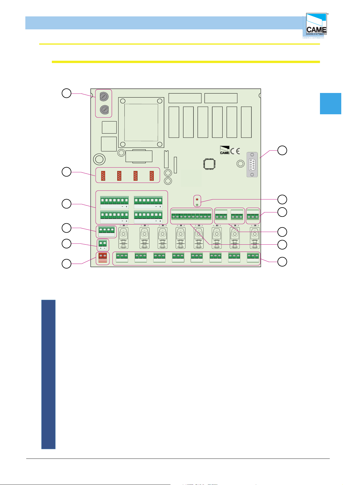
RBM 84 - ELECTRICAL CONNECTIONS
RBM 84 Motherboard– description
1
1
1
2
R800
-
700
700 -R800
R
R
Hardware - CONNECTIONS
2
3
4
3
2
R800
-
00
00 -R800
R7
R7
4
0
R800
R80
-
00 -R800
700
R
R700 -
R700 -R 800
R7
1345
2
ON
Cap1
12
MODEM
MODEM
3
ABS1
ABS1
GND
OUT
GND
OUT
ABS1
ABS1
GND
OUT
GND
OUT
P1
P2 P3 P4 Com Com
P5
P6 P7 P8
ABGND
ABGND
ABGND
4
ABC
D
1
N
B
ER
G
R
A
Y
H
R
C
TE
BAT
5
Y
R
E
T
T
A
B
L N
NC NO C
ABGND
L
N
6
OUT1
NONC C
ABGND
OUT2
NO CNC
ABGND
OUT3
NO CNC
ABGND
OUT4
NO CNC
ABGND
OUT5
NO CNC
ABGND
OUT6
NO CNC
ABGND
OUT7
NO CNC
ABGND
OUT8
1 - Protection fuses (Line) 315 mA and circuit fuses (command board) 630 mA
2 - Connectors for R700 and R800 boards
3 - Terminals for connecting the sensors
4 - Terminals for connecting battery charger (BN1 2 x 12 V)
5 - Clamp for connecting batteries
11
10
9
8
7
6 - 230 V line connection
7 - Terminals for connecting the devices to command 10 A max. to 230 V per contact
8 - Terminals for connecting the digital input devices
9 - Terminals for connecting the REM extensions
10- Clamp for connecting the PC30
11- LED notifying “active circuit (red)” and “communication in progress (green)”
12- Connector for modem
ENGLISCH
cap. < 1 > pag.< 2 >
Page 3

5ON4321
ON
4321
RBM 84 - ELECTRICAL CONNECTIONS
REM Motherboard – description
Hardware - CONNECTIONS
9
10
ON
2
1345
CONTROL BOARD
FUSE 630mA
Cap1
3
LINE FUSE 1,6A
2
NC NO CL2L1
OUT1
NC NO C
1 8
1 - Terminals for powering board, 230 V
2 - Power protection fuse
OUT2
1 - AF43S/AF150/R700/R800
1
2
CANCELLIAUTOMATICI
CONTROL
BOARD
REM
12
7
2 - AF43S/AF150/R700/R800
TSP00/LT001
S1 GND S1 GND
12
REM
ABGND
1
S5000/S6000/S7000
ABAB
12
4
REM
ABGND
2
5
4
6
11
3 - Circuit protection fuse
4 - Terminals for connecting sensors (keyboards, readers)
5 - Board connectors for signal decoding (sensors, remote controls)
6 - Terminals for connecting antenna
7 - Terminals for connecting the digital input devices
8 - Terminals for connecting the devices to command
9 - LED notifying “communication active”
10- REM addresses selector
11- Terminals for connecting to other REMs or RBM84
ENGLISCH
cap. < 1 > pag.< 3 >
Page 4

RBM 84 - ELECTRICAL CONNECTIONS
PC30 - description
Hardware - CONNECTIONS
10 9
Cap1
8
11
3
4
6
7
2
5
1
1 - Power input, 12 V A.C.
2 - RS232 serial port for connecting to a Personal Computer
3 - Terminals for connection to RBM84 (RS485 serial port)
4 - 12 V A.C. transformer
5 - Cable complete with 1.5 m RS232 connectors
6 - Keyboard for saving selector codes S5000/S6000/S7000
7 - Area for memorizing transmitters TAM/ATOMO
8 - Area for memorizing Card TST01 (proximity cards)
9 - Area for memorizing Card TST02 (magnetic swipe cards)
10- LED notifying “supply presence”
11- LED notifying “registered code “ and “code already present”
ENGLISCH
cap. < 1 > pag.< 4 >
Page 5
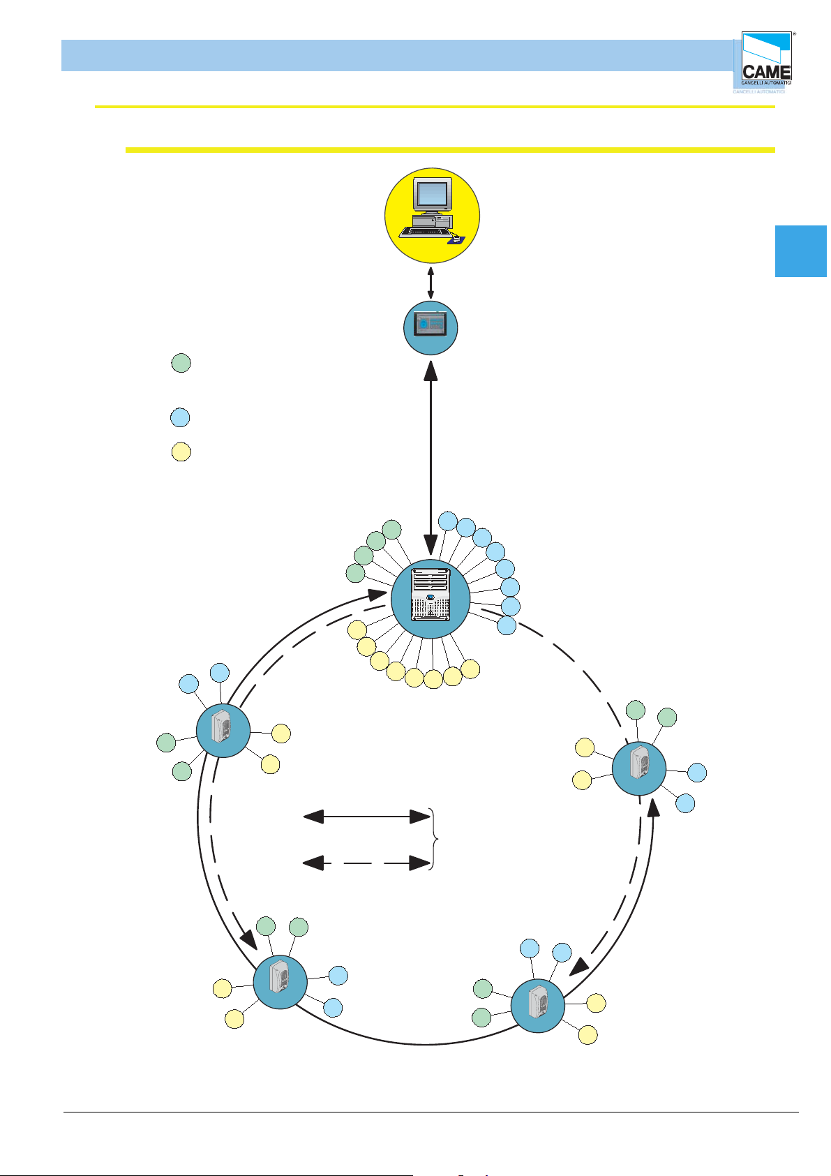
RBM 84 - ELECTRICAL CONNECTIONS
General system layout
Hardware - CONNECTIONS
A = Control devices:
A
- radio transmitters Atomo/Tam
- keypads S5000/S6000/S7000
- sensorsTSP00/LT001
B = Outputs (automation control)
B
= Digital imputs :
C
B
B
max 1,5 m
Cap1
PC30
max 1000 m
B
A
A
A
A
C
C
RBM84
C
C
C
B
B
B
B
B
B
B
C
C
C
ENGLISCH
A
A
A
A
CAME
REM
C
C
C
C
C
C
single connetion
max 1000 m
double connection
max 1000 m
A
A
CAME
REM
B
B
max 60 REM units for both types
of serial connection
B
B
A
A
CAME
REM
C
REM
CAME
B
B
C
cap. < 1 > pag.< 5 >
Page 6

Hardware - CONNECTIONS
FUSE 630m A
CONTROL B OARD
PSIO1
TRANSFORMER TERMINAL B LOC K
LINE FUSE 5A
CAME
U2
REM
REM PC 30
ABGND
ABGND
ABGND
RBM 84 - ELECTRICAL CONNECTIONS
rbm84 connection <----> PC30 <----> Personal Computer
PC30
COM
Cap1
Cable, 1.5m
INCLUDED
for RS232 serial ports
complete with connectors
RBM 84
GND B A
Cable not included
type recommended:
shielded bipolar
min. 2 x 0.5 mm
RS232
2
12 V AC transformer
INCLUDED
for networks 230 V A.C. - 50-60Hz
consumption 800 mA
protected by thermal fuse
operating temperature from -10 to +40°C
ENGLISCH
cap. < 1 > pag.< 6 >
Page 7

Hardware - CONNECTIONS
FUSE 630m A
C ONTROL B OA RD
PSIO1
TRANSFORMER TERMINAL B LOC K
LINE FUSE 5A
CAME
U2
REM
REM PC 30
ABGND
ABGND
ABGND
CANCELLI AUTOMATICI
CONTROL
BOARD
REM
21
12
ABGND
1
REM
ABGND
2
REM
RBM 84 - ELECTRICAL CONNECTIONS
rbm84 connection <----> REMs (with one section)
Cable not included
type recommended:
shielded bipolar
min. 2 x 0.5 mm
2
RBM 84
Cap1
Connection to one draws: RBM84 is found to
the extremity of the run you extract
RBM84
CAME
REM
from RBM84 to the last REM,
the distance (or the route
of the connection cable) must
be at most 1000 m
CAME
REM
Each REM is identifi ed by RBM84 through
a progressive number sequence (from 1 to 60)
irrespective of the position along the
the connection cable route; this number (also called
address) must be set on the related
dip switch in the REM motherboard.
See Section 1, page 15
CAME
REM
REM
CAME
REM
ENGLISCH
CAME
from the next REM , for a maximum of
60 units
INPUT AND OUTPUT CONNECTABLE ON TERMINAL
(
1 OR 2 IN DIFFERENTLY)
BOARD
cap. < 1 > pag.< 7 >
Page 8

Hardware - CONNECTIONS
FUSE 630m A
CONTROL B OARD
PSIO1
TRANSFORMER TERMINAL B LOC K
LINE FUSE 5A
CAME
U2
REM
REM PC 30
ABGND
ABGND
ABGND
CANCELLI AUTOMATICI
CONTROL
BOARD
REM
21
12
ABGND
1
REM
ABGND
2
REM
CANCELLI AUTOMATICI
CONTROL
BOARD
REM
21
12
ABGND
1
REM
ABGND
2
REM
RBM 84 - ELECTRICAL CONNECTIONS
rbm84 connection <----> REMs (with two sections)
RBM 84
Cap1
Cable not included
type recommended:
shielded bipolar
min. 2 x 0.5 mm2
a progressive number sequence (from 1 to 60)
connection cable route; this number (also called
dip switch selector in the REM motherboard.
tratta A*
Each REM is identifi ed by RBM84 through
irrespective of the position along the
address) must be set on the related
See Section 1, page 15
for the subsequent REM
(INPUT AND OUTPUT CONNECTABLE ON TERMINAL BOARD
1 O 2 INDIFFERENTLY)
Cable not included
type recommended:
shielded bipolar
min. 2 x 0.5 mm2
Connection to two drawn: RBM84 can be in
any point of the run extracts
RBM84
CAME
REM
from the fi rst to thelast REM, the
distance (or the route
of the connection cable) must
be a maximum of 1,000 m
CAME
REM
CAME
REM
CAME
REM
tratta B
ENGLISCH
from the next REM , for a maximum
of 60 units
INPUT AND OUTPUT CONNECTABLE ON TERMINAL
(
BOARD
1 OR 2 IN DIFFERENTLY)
* the sum of the serial connected REMs
on the A+B section must be
60 units max.
from the next REM , for a maximum
of 60 units
INPUT AND OUTPUT CONNECTABLE ON TERMINAL
(
1 OR 2 IN DIFFERENTLY)
BOARD
cap. < 1 > pag.< 8 >
Page 9
Hardware - CONNECTIONS
21
1 - AF43S/AF150/R
2 - AF43S/AF150/R
S1 GND S1
1
TSP00/LT0
REM REM
LT0 0 1
R501/2
S5000
S6000
S7000
1
3
TSP 00
LT0 0 1
S5000
S6000
S7000
TSP 00
R501/2
R700-R800
1
R700-R800
2
R700
-R
800
1
R700
-R
800
2
ABS1
GND
OUT
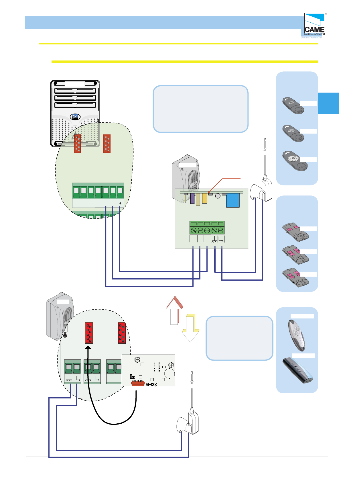
RBM 84 - ELECTRICAL CONNECTIONS
Connection rbm84/rem <----> sensor: remote control
RBM84
On RBM84, you must connect
the R501N receiver (which includes
inserting the AF43S radiofrequency
card into the dedicated connector) and
an TOP-A433N aerial to the receiver
itself
TOP-A433N
R501N
AF43S
CAME
-
+
OOU T
ATOMO
CAME
CAME
CAME
TAM
CAME
AT01
Cap1
AT02
AT04
T432
REM
CAME
RBM84
REM
TOP-A433N
T434
CAME
T438
CAME
T432A
Simply insert an AF43S
radiofrequency card in
the REM and connect a
TOP-A433N antenna
on the REM motherboard
T302A
ENGLISCH
cap. < 1 > pag.< 9 >
Page 10

Hardware - CONNECTIONS
CA NC ELLIAU TOM AT ICI
CONTROL
BOAR D
REM
12
C
2
1
1-AF4 A F150
2 -AF 43S /AF15
S5
S1 G N D S1 GN D
12
TS P 00/L T001
ABG
1
REM
REM
LT0 0 1
R501/ 2
S5000
S6000
S7000
1
3
TSP 00
LT001
S5000
S6000
S7000
TSP 00
R501/ 2
R700 -R 800
R 700 -R 800
2
R700 - R800
R
700 - R 800
2
RBM 84 - ELECTRICAL CONNECTIONS
Connection rbm84/rem <----> Keyboard selector serious S5000
RBM84
Cap1
REM
CANCELLI AUTOMATICI
R800
RBM84
REM
S5000
1
4
7
3
6
5
E
8
012
ENGLISCH
S5000
CANCELLI AUTOMATICI
R800
3
1
6
5
E
4
8
7
012
cap. < 1 > pag.< 10 >
Page 11

Hardware - CONNECTIONS
1
3
LT0 0 1
S5000
S6000
S7000
TSP 00
R501/ 2
R700-R800
R 700 -R 800
2
R700 - R800
R
700 - R 800
2
CA NC ELLIAU TOM AT ICI
CONTROL
BOAR D
REM
12
C
2
1
1-AF4 A F150
2 -AF 43S /AF15
S
S1 G N D S1 GN D
12
TS P 00/L T001
ABG
1
REM
REM
RBM 84 - ELECTRICAL CONNECTIONS
Connection rbm84/rem <----> Keyboard selector serious S6000 / S7000
RBM84
Cap1
REM
CANCELLI AUTOMATICI
R800
S6000 / S7000
A
B
REM
2
1
5
4
E
3
6
CAME
ENGLISCH
CANCELLI AUTOMATICI
R800
A
B
S6000 / S7000
2
1
5
4
E
3
6
CAME
cap. < 1 > pag.< 11 >
Page 12

Hardware - CONNECTIONS
CA NC ELLIAU TOM AT ICI
CONTROL
BOAR D
REM
21
1-AF4 A F150
2 -AF 43S /AF1
S1
TS
AB
1
REM
S5000
S6000
S7000
1
3
LT001
S5000
S6000
S7000
TSP 00
R501/ 2
R 700 -R 800
R
700 - R 800
A
B
CANCELLIAUTOMATICI
R700
RBM 84 - ELECTRICAL CONNECTIONS
Connection rbm84/rem <---> Sensor trasponder for devices of proximity
RBM84
Proxmimity card
GND
R700
RBM84
TSP00
CAME
AME
C
TST01
Proxmimity card reader
Cap1
ENGLISCH
REM
Proxmimity card reader
Proxmimity card
TSP00
GND
S1
CAME
CAME
TST01
cap. < 1 > pag.< 12 >
Page 13

Hardware - CONNECTIONS
21
1 -AF 43S /AF 150/R 700/R 800
0
S1 G N D S1 GN D
S7000
1
3
LT0 0 1
S5000
S6000
S7000
TSP 00
R501/2
ABS1
GND
OUT
RBM 84 - ELECTRICAL CONNECTIONS
rbm84/rem connection <----> Sensor for magnetic swipe cards
RBM84
Magnetic cards
R700
Magnetic cards swipe
reader
RBM84
REM
GND
S1
LT001
TST02
ACCESSCONTROL
Cap1
REM
ENGLISCH
Magnetic cards
TST02
R 700
ACCESSCONTROL
LT001
Magnetic cards swipe
reader
GND
S1
cap. < 1 > pag.< 13 >
Page 14

Hardware - CONNECTIONS
CANCELLI AUTOMATICI
CONTROL
BOARD
REM
12
ABAB
12
S5000/S6000/S700
ABGND
1
REM
ABGND
2
REM
FUSE 630m A
C ONTROL B OA RD
TRA N S FO RM ER TERM INAL B LOC K
LINE FUSE 5A
U2
REM
REM PC 30
DIGITAL INPUT
P1
P2 P3 P4 Com Com
P5
P6 P7 P8
RBM 84 - ELECTRICAL CONNECTIONS
Connection rbm84/rem <----> contact digital inputs
RBM84
Cap1
REM
RBM84
REM
CAME
ENGLISCH
cap. < 1 > pag.< 14 >
Page 15

5ON43
2
1
ON
43
2
1
5ON4321
ON
4321
REM n° 1
5ON4321
ON
4321
REM n° 2
5ON4321
ON
4321
REM n° 3
5ON4321
ON
4321
REM n° 4
5ON4321
ON
4321
REM n° 5
5ON4321
ON
4321
REM n° 6
5ON4321
ON
4321
REM n° 7
5ON4321
ON
4321
REM n° 8
5ON4321
ON
4321
REM n° 9
5ON4321
ON
4321
REM n° 10
5ON4321
ON
4321
REM n° 11
5ON4321
ON
4321
REM n° 12
5ON4321
ON
4321
REM n° 13
5ON4321
ON
4321
REM n° 14
5ON4321ON4321
REM n° 15
5ON4321ON4321
REM n° 16
5ON4321ON4321
REM n° 17
5ON4321ON4321
REM n° 18
5ON4321ON4321
REM n° 19
5ON4321
ON
4321
REM n° 20
5ON4321ON4321
REM n° 21
5ON4321
ON
4321
REM n° 22
5ON4321
ON
4321
REM n° 23
5ON4321
ON
4321
REM n° 24
5ON4321ON4321
REM n° 25
5ON4321ON4321
REM n° 26
5ON4321ON4321
REM n° 27
5ON4321
ON
4321
REM n° 28
5ON4321ON4321
REM n° 29
5ON4321ON4321
REM n° 30
5ON4321ON4321
REM n° 31
5ON4321ON4321
REM n° 32
5ON4321ON4321
REM n° 33
5ON4321ON4321
REM n° 34
5ON4321ON4321
REM n° 35
5ON4321ON4321
REM n° 36
5ON4321
ON
4321
REM n° 37
5ON4321
ON
4321
REM n° 38
5ON4321
ON
4321
REM n° 39
5ON4321
ON
4321
REM n° 40
5ON4321ON4321
REM n° 41
5ON4321ON4321
REM n° 42
5ON4321ON4321
REM n° 43
5ON4321ON4321
REM n° 44
5ON4321ON4321
REM n° 45
5ON4321ON4321
REM n° 46
5ON4321ON4321
REM n° 47
5ON4321ON4321
REM n° 48
5ON4321ON4321
REM n° 49
5ON4321ON4321
REM n° 50
5ON4321ON4321
REM n° 51
5ON4321
ON
4321
REM n° 52
5ON4321ON4321
REM n° 53
5ON4321ON4321
REM n° 54
5ON4321ON4321
REM n° 55
5ON4321ON4321
REM n° 56
5ON4321ON4321
REM n° 57
5ON4321ON4321
REM n° 58
5ON4321ON4321
REM n° 59
5ON4321ON4321
REM n° 60
DIP
A
DIP
B
RBM 84 - ELECTRICAL CONNECTIONS
DIP
ON
4321
Hardware - CONNECTIONS
5ON4321
Cap1
ENGLISCH
cap. < 1 > pag.< 15 >
Page 16

S E C T I O N 2
RBM84 - software
SYSTEM CONFIGURATION
CONTENTS
SUBJECT PAGE
Main dialogue window
System configuration window ............................................................................................. 3
Confi gure PC30 ............................................................................................................. 4
Select the number of REMs connected ............................................................................. 5
Assign a name to theRBM84- and REM- connected outputs .................................................. 6
Defi ne user groups ........................................................................................................ 6
Setting traffi c lights (if present) ....................................................................................... 7
Confi gure the control sensors connected to RBM84 ........................................................... 8
Sensor Type ................................................................................................................. 8
Sensor function ............................................................................................................. 8
Associate the sensor to a connected output ........................................................................ 8
Associate the sensor to a traffi c-light control .................................................................... 9
##Cost/Tariff Function (differentiated ***output) ...............................................................10
Associate the sensor to a user group ............................................................................ 11
Confi gure the outputs connected to RBM84 ..................................................................... 12
Activate the RBM84 outputs ............................................................................................12
Relay function ............................................................................................................ 13
Confi gure the digital entrancesconnected to RBM84 ......................................................... 14
Associate the digital devices to the outputs .................................................................... 14
Confi gure the REMs ..................................................................................................... 15
Assign a name to the REMs ........................................................................................... 15
Confi gure the control sensors connected to the REM ........................................................ 16
Sensor type(REM)......................................................................................................... 16
Function of the sensor (REM) ........................................................................................ 16
Association of the sensor to aconnected (REM) output ..................................................... 17
Association of the sensor to a traffi c-light control (REM) .................................................. 17
Association of the sensor to a user group (REM) .............................................................. 18
Confi gure the outputs of the REM ................................................................................... 19
Activate the outputs of the REM .................................................................................... 19
Relay function(REM) ..................................................................................................... 20
Confi gure the digital entrances of the REM ...................................................................... 21
Assign the digital devices to an output (REM) .................................................................. 21
.................................................................................................... 2
Page 17
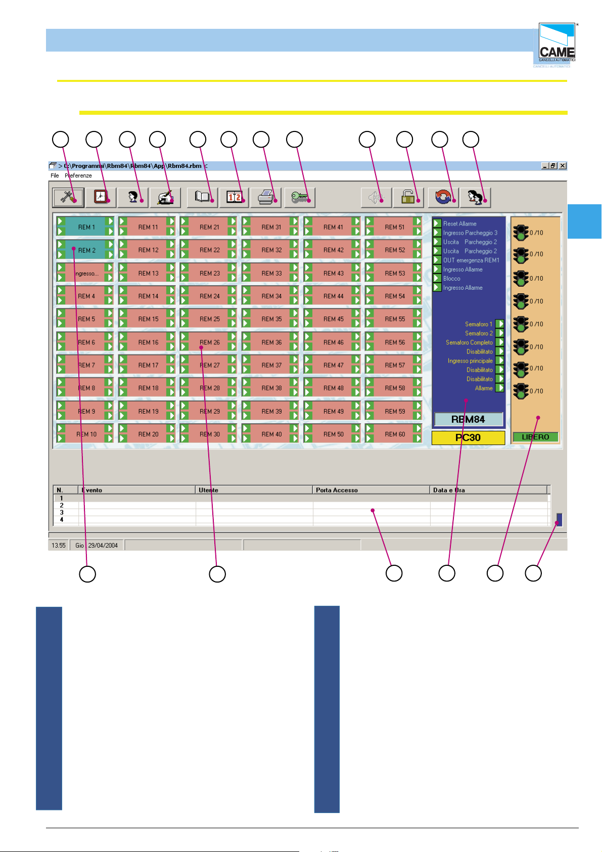
RBM 84 -Software
Main dialogue window
Software - SYSTEM CONFIGURATION
1 2 3 4 5 6 7 8 9 10 1 1
11
12
Cap 2
1718
1 - Button for opening the System Configuration window
2 - Button for opening timings
3 - Button for opening User Configuration Window
4 - Button for opening Update System Window
5 - Button for opening History
6 - Button for opening Daily History
7 - Button Password window
9 - Button for the audio alarm shut-down
10- Button for system Block/Clearing
ITALIANO
16
15
1314
11 - Button for opening Project Management window
12 - Button for opening Occupancy Window
13 - Lit panel for signalling communication
with the board.
14 - Traffic lights section, indicates whether the traffic
lights are connected, their positions and their
status.
15 - digital RBM84 inputs and outputs section
16 - Display window last 4 passages (in real time)
17 - REMs not communicating (red)
18 - REM communicating (green)
cap. < 2 > pag. < 2 >
Page 18
Software - SYSTEM CONFIGURATION
RBM 84 -Software
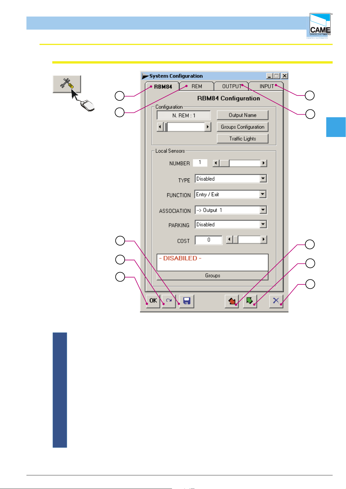
System Confi guration Window
1
2
3
4
10
9
Cap 2
8
7
5
1 - RBM84 Configuration menu
2 - REM configuration menu
3 - Save key
4 - Cancel changes key
5 - Confirm changes key
6 - Escape key
7 - Key for reading RBM84 configuration
8 - Key for writing configuration on RBM84
9 - Configuration menu for RBM84 outputs
10- Configuration menu for RBM84 digital inputs
6
ITALIANO
cap. < 2 > pag. < 3 >
Page 19

RBM84 -Software
PC30 Confi guration
Software - SYSTEM CONFIGURATION
Cap 2
1
When the window is
opened, it shows the list of
the COM available on the
2
PC
3
In the PC30 configuration screen, you must select the PC’s port connection which
connects PC30 (normally COM1).
Caution! This operation should be performed before starting any programming
and/or configuration operation described in the following pages or in later sections, otherwise every
software request for
updating and/or saving will elicit a COMMUNICATION ERROR.
ITALIANO
cap. < 2 > pag. < 4 >
Page 20

Software - SYSTEM CONFIGURATION
RBM84 -Software
Select the number of REMs connected to the RBM84 board
In the Configuration area of the RBM84 board , set the
number of REMs connected, clicking on button [N REM]
and dragging the scroll bar
1
Cap 2
2
Caution! at the end of every group of opera tions, you must update to make the changes effective
to adjourn
Assign a name to the RBM84- and REM-connected outputs
Click on [Output] ...
1
2
... and type in the OUTPUT DEFINITION
window the selected name for the outputs
connected both to the RBM84 and the REMs
ITALIANO
This procedure is optional: by default, the
system assigns a name for each output
available in the system (from “Output 1”
a “Output 128”).( The first 8 outputs are
RBM84s and the ones after are REMs)
It is recommended, however, to name all
the outputs to make subsequent
configurations easier and safer
to adjourn
3
4
cap. < 2 > pag. < 5 >
Page 21
RBM84 -Software
Defi ne the user groups
Software - SYSTEM CONFIGURATION
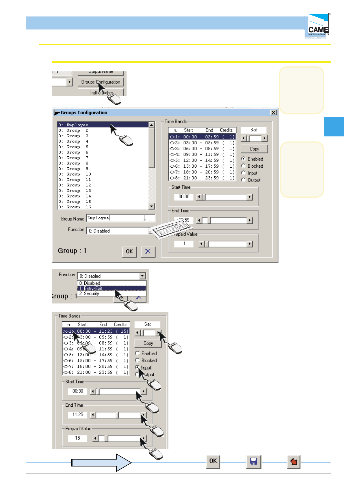
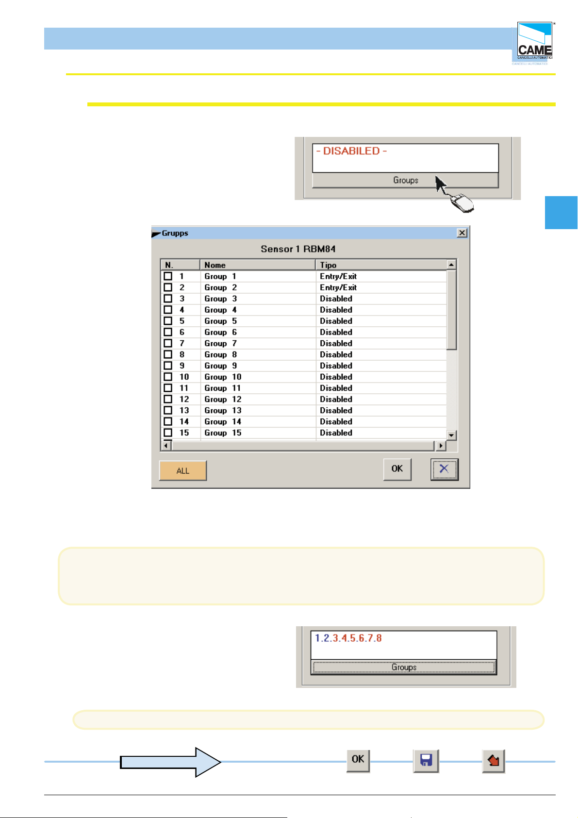
1-Click on CONFIGURE GROUPS
2-Select the group to set
1
3- Assign a name to the group selected
(N.B. it is
compulsory
to enable
at least one
group)
Cap 2
2
(N.B. it is
possible to
assign
up to 8
time bands)
per day
3
4
6 5
7
8
9
4- Associate a function to the individual group:
DISABLED prevents all
movement for the whole group.
ENTRY/EXIT allows the
group the normalentry and
exit operations.
SAFETY allows entry at
any time, even if access is
made during the blocked time bands.
5- Select the day to set
6- select the band to set
7- Assign a function to the individual band.
ENABLED allows the group to enter and
exit during that set time band.
BLOCKED prevents both
entering and exiting.
ENTRY allows entry only in
the set time band
EXIT allows exit only in
the set time band
8- Select the band start time.
9- Select the band end time.
10- Associate a credit value to the band
ITALIANO
10
to adjourn
cap. < 2 > pag. < 6 >
Page 22

Software - SYSTEM CONFIGURATION
RBM84 -Software
Setting traffi c lights (if present)
1-Click on TRAFFIC LIGHTS
1
Cap 2
2
3
4
5
6
2- select the traffic light to set.
3- Assign a name to it.
4- Assign a maximum capacity.
5- If there are occupied parking spaces during installation, simply
mark them in the ‘Occupied’ Box.
6- You can select the function type. With the Autonomous function, the traffic light is
considered independent and is therefore not counted in the
total. With the Complete function, however, the traffic light is part of a group of traffic
lights, and when everything is completed, the total will indicate this.
7
7- Once set, the new values must be assigned to the traffic light
Caution! At the end of every group of operations, you must update to make the changes effective
to adjourn
ITALIANO
cap. < 2 > pag. < 7 >
Page 23
Software - SYSTEM CONFIGURATION
TRA N S FO RM ER TERM INAL B LOC K
LINE FUSE 5A
LT0 0 1
R501/2
S5000
S6000
S7000
1
3
TSP 00
LT0 0 1
S5000
S6000
S7000
TSP 00
R501/2
RBM84 -Software
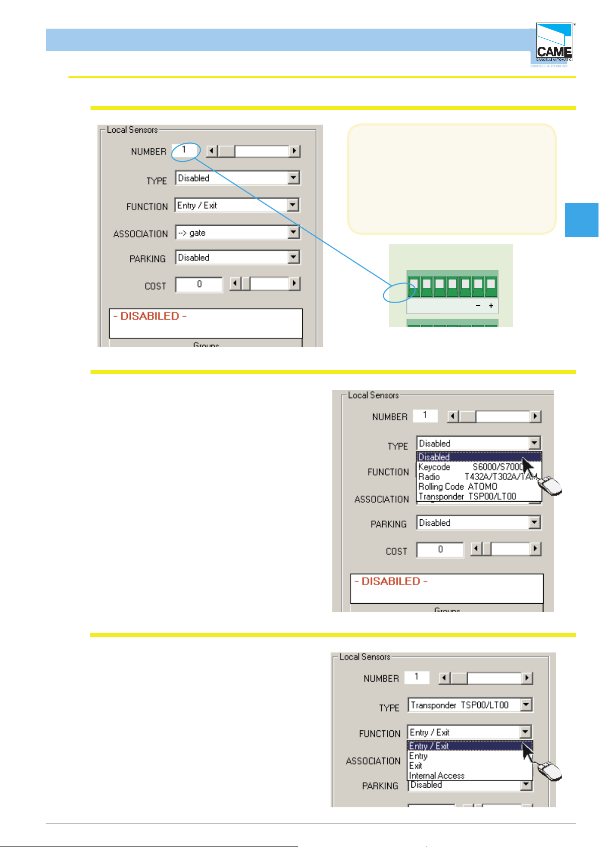
Confi guring the control sensors connected to RBM84
In the Local Sensors area of the
RBM84 board you must confi gure the
type, function and associations of each
command device connected to RBM84.
The sensor number corresponds
exactly to the sensor connected to the
terminal board labelled with the same
number; see fi gure
Cap 2
Sensor type
In the Typepull-downmenu, select the type
of sensor connected:
- S5000/S6000/S7000 keypad
- remote controls series, TAM or ATOMO
- transponder TSP00/LT001
and confirm with [OK]
ABS1
GND
OUT
Sensor function
In the Function pull-down menu , select
the function of the connected sensor:
- entry and exit
- entry only
- exit only
- internal access
and confi rm with [OK]
ITALIANO
cap. < 2 > pag. < 8 >
Page 24

Software - SYSTEM CONFIGURATION
RBM84 -Software
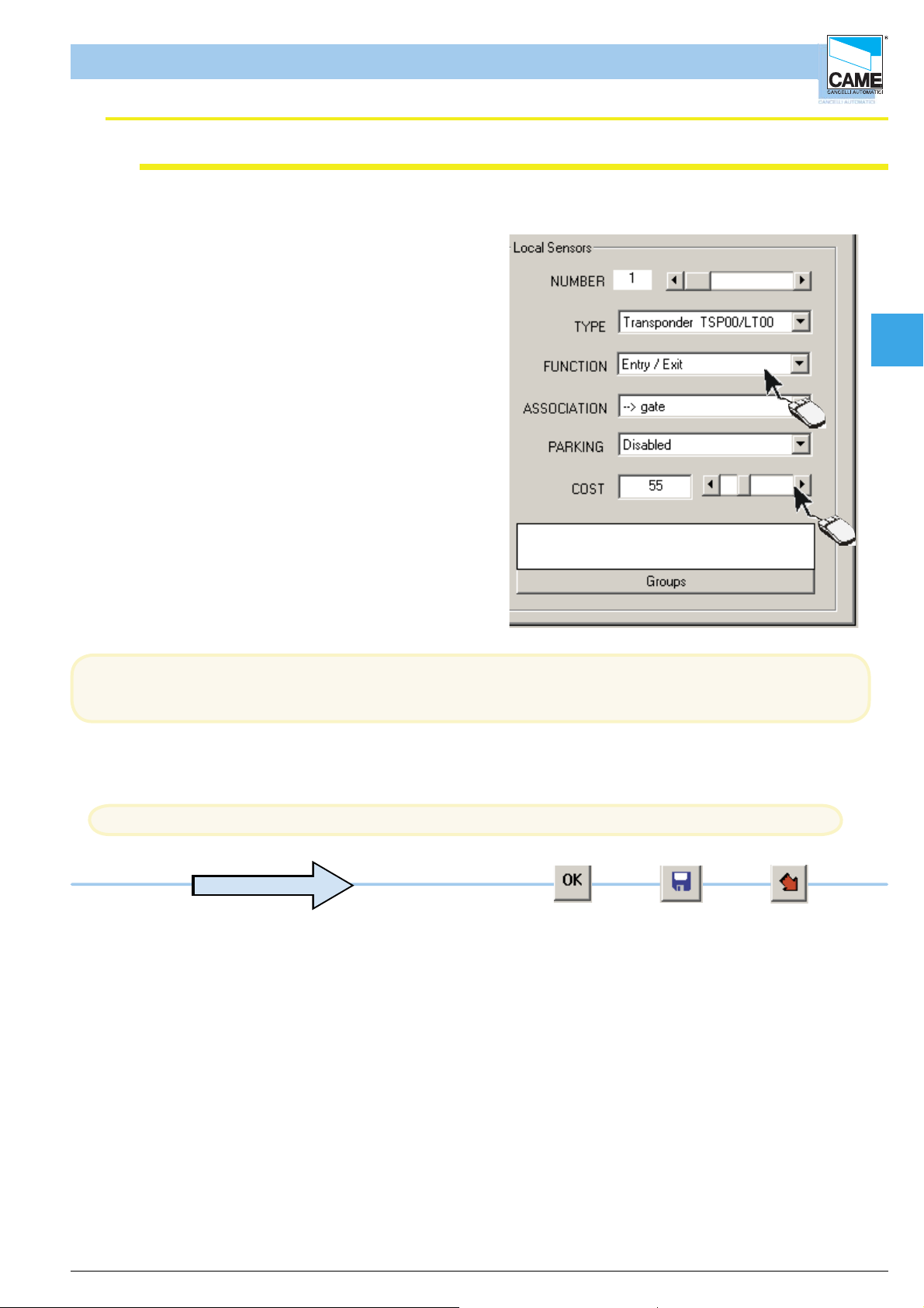
Associating the sensor to an exit
In the Associationpull-down menu , select
the association of the device with one of the
connected exits
and confi rm with [OK]
Cap 2
Associating the sensor to a traffi c-light control
In the Car-parkpull-down menu , select
which car park must be associated and
confi rm with [OK]
ITALIANO
cap. < 2 > pag. < 9 >
Page 25
Software - SYSTEM CONFIGURATION
RBM84 -Software
Cost Function (differentiated output)
1- To use the cost function, set the
sensor as internal passage.
2- Set the value associated to the sensor,
Cap 2
1
To work correctly, the user must have an IN status, either by entering the system
or by changing the status manually. (See Section 4, page 18)
Caution! at the end of every group of operations, you must update to make the changes effective
to adjourn
2
ITALIANO
cap. < 2 > pag. < 10 >
Page 26
Software - SYSTEM CONFIGURATION
RBM84 -Software
Associating the sensor to a user group
Click on the [GROUP] button...
Cap 2
... and, in the GROUPS window, tick the user group to be associated with the device; confirm with [OK]
This procedure is not optional and at least one group must be assigned; the [ALL] button associates or
disassociates all of the device’s user groups.
The numbers appearing in BLUE are the
enabled groups while those in RED
are the disabled ones.
Caution! at the end of every group of operations, you must update to make the changes effective
to adjourn
ITALIANO
cap. < 2 > pag. < 11 >
Page 27

Software - SYSTEM CONFIGURATION
TRANSFORMER TERMINAL B LOC K
LINE FUSE 5A
REM
REM PC 30
LT0 0 1
R501/ 2
DIGITA L INPUT
3
4
TSP 00
LT001
S5000
S6000
S7000
TSP 00
R501/ 2
NO C
NO CNC
NO CNC
NO CNC
NO CNC
NO CNC
RBM84 -Software
Confi guring the outputs connected to RBM84
In the OUTPUTS board,
the outputs connected to RBM84 must
be programmed
with the function type and any activation
time
of the related relays;
If there are no automations connected,
select or leave “Disabled” as
suggested in the menu.
The output number corresponds
exactly to the number labelled on the
device connected to the
terminal board; see figure
Cap 2
Activating the RBM84 outputs
Select the output (1-8) and match it to one
of the names/devices appearing in the pulldown menu
1- Select the output (1-8)
2- And match it to one of the names/devices
appearing in the pull-down menu
N C N O C
ABGND
OUT1
N ON C C
ABGND
OUT2
N C
A
O
1
2
In the pull-down menu of the Local Outputs area there appear (by default) the traffi c light exits and the
normal exits
as defi ned in Assign Exit Name
The exit device matching is independent of the physical connection of the latter on RBM84 or REM;
ITALIANO
cap. < 2 > pag. < 12 >
Page 28
Software - SYSTEM CONFIGURATION
RBM84 -Software
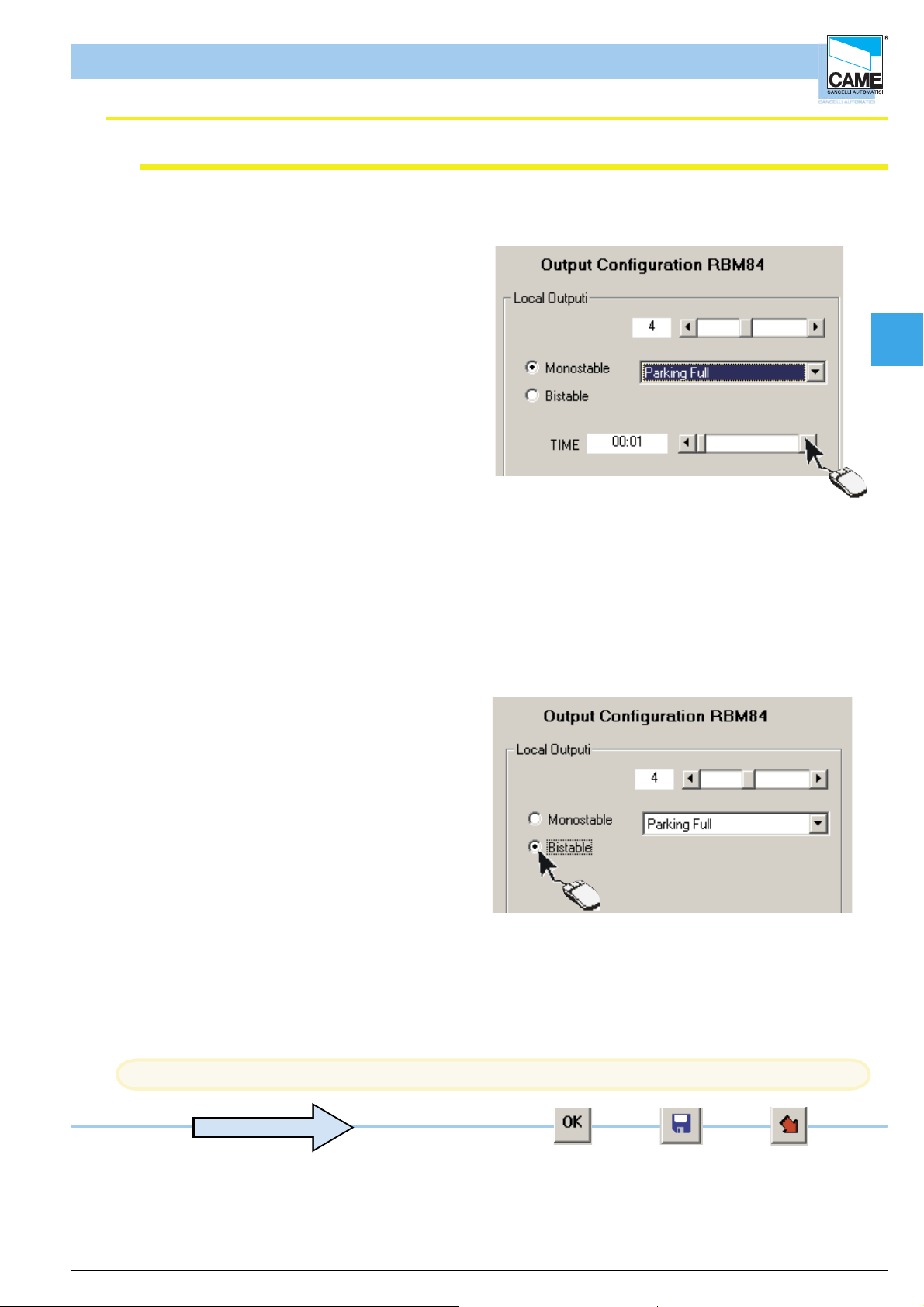
Relay function
The monostable function
is proposed as default, therefore we may
select the relay activation time by clicking
on the scroll-down bar, which can vary
between 1 second and 10 minutes.
Cap 2
If, instead, the bistable function is required,
click on the related box
Caution! at the end of every group of operations, you must update to make the changes effective
to adjourn
ITALIANO
cap. < 2 > pag. < 13 >
Page 29

Software - SYSTEM CONFIGURATION
RBM84 -Software
Confi gure the digital entrances connected to RBM84
All the supplementary command and
control devices must be programmed
in the configuration dialog
of the digital Entrances (INGR), (for
instance safety buttons, sensitive
footboards, alarms etc.)
that will be connected to RBM84 and
act on any of the RBM84 and REM
outputs
N.B. There are also functions other than
the normal outputs
-Block
-Entry alarm
-Reset alarm
-Car-park entry
-Car-park exit.
Cap 2
Associate the digital devices to the exits
For each entrance, select an output which this
digital device will act on; the related box must
also be ticked if the contact of the device is NC
type (normally closed)
3
1- Select the entrance to set
2- For each entrance, assign an output
or device which this digital apparatus
will act on.
3- Tick the related box if the
device is NC type (normally closed)
Caution! at the end of every group of operations, you must update to make the changes effective
The digital entrance/exit association is
independent of the physical position of the exit
on RBM84 or REM;
2
1
ITALIANO
to adjourn
cap. < 2 > pag. < 14 >
Page 30
RBM84 -Software
Confi guring the REMs
Software - SYSTEM CONFIGURATION
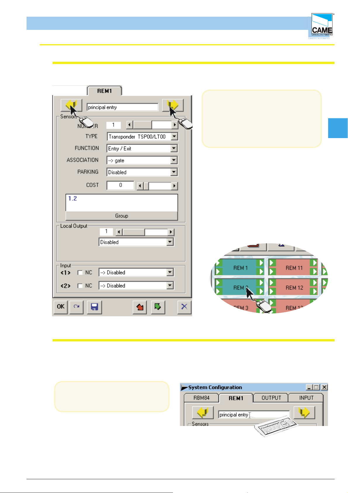
In the same way as with RBM84,
the REMs configuration dialog must be
used to program all the control devices,
the exits and digital inputs connected to
them; to move from one REM to the other,
simply click on the yellow arrow or on the
related icon in the system display window
A feature of the system display
window is that if the REMs
are green they are
communicating, whereas if they
are red they are not
Cap 2
Assign a name to the REMs
The name typed here has only a
recognition function and does not
interact with the software.
ITALIANO
cap. < 2 > pag. < 15 >
Page 31

Software - SYSTEM CONFIGURATION
0
RBM84 -Software
Confi gure the control sensors connected to the REMs
In the Sensors area of the REM board n, the type,
function and associations of both the control devices
connected to the REM must be configured.
The sensor number corresponds exactly to the
sensor connected to the terminal board labelled with
the same number; see figure
Sensor type (REM)
In the Type pull-down menu, select the
type of
sensor connected:
- S5000/S6000/S7000 keypad
- remote controls of the TAM or ATOMO
series
- TSP00/LT001 transponder
and confi rm with [OK]
CANCELLI AUTOMATICI
CONTROL
REM
C
1
BOARD
2
A B GND
1 2
TSP00/LT001
S1 GNDS1 GND
1 2
REM
A B GND
1
S5000/S6000/S700
A B A B
1 2
Cap 2
REM
2
Function of the sensor (REM)
In the Function pull-down menu, select the
function of the connected sensor:
- entry and exit
- entry only
- exit only
- internal access
and confirm with [OK]
ITALIANO
cap. < 2 > pag. < 16 >
Page 32

Software - SYSTEM CONFIGURATION
RBM84 -Software
Associating the sensor to an exit (REM)
In the Association pull-down menu,
select the device association
with one of the connected exits and
confi rm with [OK]
Association of the sensor to a traffi c-light control (REM)
Cap 2
In the Car-park pull-down menu, select
the association with a Traffic light
##Cost/Tariff Function (differentiated output) (REM)
1- To use the cost function, set the
sensor as internal passage.
2- Set the value associated to the sensor,
1
2
To function correctly, the user must be with the current status set at IN, i.e. by making an access
into the system or changing the status manually. (See Section 4, page 18)
Caution! at the end of every group of operations, you must update to make the changes effective
to adjourn
ITALIANO
cap. < 2 > pag. < 17 >
Page 33

Software - SYSTEM CONFIGURATION
RBM84 -Software
Associating the sensor to a user group (REM)
Click on the [GROUP] button...
Cap 2
... and, in the GROUPS window, tick the user group to associate the device with; then confirm with [OK]
This procedure is not optional and you must assign at least one group; the [ALL] button associates or
dissociates all the user groups from the device.
The numbers that appear written in BLUE are the
groups enabled, whereas those written in RED
are the disabled ones
Caution! at the end of every group of operations, you must update to make the changes effective
to adjourn
ITALIANO
cap. < 2 > pag. < 18 >
Page 34

Software - SYSTEM CONFIGURATION
REM
RBM84 -Software
Confi guring the REM outputs
In the Local Outputs area of the REM board, for
both the outputs the function type must
be programmed
along with any interval of relay activation;
If there are no automations connected, select or
leave “Disabled” as supported by the menu.
Cap 2
Activating the REM outputs
Select the output and associate it to one of
the names/devices appearing in the pulldown menu
1
NC NO CL2
OUT1
NC NO C
OUT2
In the pull-down menu of the Local Outputs area , appear as default the eight traffi c light outputs
and the normal outputs defined in Assign Output Nameas well as an output called Alarm and one
called Intrusion alarm;
The exit device matching is independent of the physical connection of the latter on RBM84 or REM.
The output number corresponds exactly to the device connected to the terminal board labelled with the
same number; see figure
ITALIANO
cap. < 2 > pag. < 19 >
Page 35

Software - SYSTEM CONFIGURATION
RBM84 -Software
Relay function
The monostable function is
default so we can select the
relay activation time by clicking on the
scroll-down bar
Cap 2
If instead you want the bistable function , click
on the related box
The traffi c-light controlled exits are bistable only
Caution! at the end of every group of operations, you must update to make the changes effective
to adjourn
ITALIANO
cap. < 2 > pag. < 20 >
Page 36

Software - SYSTEM CONFIGURATION
RBM84 -Software
Confi guring the digital entrances of the REMs
In the inputs area of the REM n board
you must program the supplementary
command and control
devices (e.g. safety buttons, sensitive
footboards, alarms etc.) that will be
connected to the REM and act on any
one of the RBM84 and REM outputs.
Cap 2
Assign the digital devices to an output (REM)
For each entrance, select an output that this
supplementary digital device
will act on; also the related box must be
ticked if the device is type NC
(normally closed)
In the pull-down menu, there appear, in addition to the normal exits defined in Assign Exit Name,
exits/functions defined as “Block”, “Entry Alarm”, “Reset Alarm “ and “Entry” + “Exit” for each
traffic-light control;
The digital input/output association is independent of the physical position of the latter on RBM84 or
REM;
Caution! at the end of every group of operations, you must update to make the changes effective
to adjourn
ITALIANO
cap. < 2 > pag. < 21 >
Page 37

S E C T I O N 3
RBM84 - SOFTWARE
CONFIGURATION
TIMINGS
CONTENTS
SUBJECT PAGE
Timings configuration window .................................................................................... 2
Tariffs configuration dialog........................................................................................... 3
Prepaid Values ............................................................................................................ 3
Discount levels ........................................................................................................... 4
Configuration dialog-User Time Bands ...................................................................... 5
Configuration dialog-Blocked Days ............................................................................. 6
Configuration dialogPlanned Openings and Antipassback ......................................... 7
Configuration dialog-PlannedOpenings ..................................................................... 8
Page 38

Software - CONFIGURATION TIMINGS
RBM 84 -Software
Configuration window of the system timings
1 2 3 4
Cap 3
ENGLISCH
10
9 8
1 - Configuration dialog of tariffs, credits and discounts.
2 - Configuration dialog of time bands.
3 - Configuration dialog of blocked and free days.
4 - Configuration dialog of planned openings and timed antipassback.
5 - Close button
6 - Button for reading RBM84 timings
7 - Button for recording timings on RBM84
8 - Button for saving to PC hard disk.
9 - Button for cancelling changes
10- OK button (confirm changes)
567
cap. < 3 > pag. < 2 >
Page 39

Software - CONFIGURATION TIMINGS
RBM 84 -Software
Confi guration dialog for tariffs
The TARIFFS dialog allows you to set the times for each credit and miminum time for free parking
for every day of the week; 4 discount levels can be defi ned.
Note The credits are only one unit of measurement that is the multiplier of each currency type (Euro, Sterling,
US Dollar etc.) for calculating the related value.
By selecting the
Daylight Saving Time
function, the RBM84
board updates itself
automatically.
.
Cap 3
Prepaid values
1- Use the dedicated scroll bars to
select the Day
2- Use the dedicated scroll bars to
set the Minimum Free Time (max
2 hours)
3- Use the scroll bars to
set the Time Associated to the
Credit (max 2 hours)
the [COPY] button copies the settings for every day of the week;
The Minimum Free Time is optional;
the value as default of the Time Associated to the Credit is 1 minute (it is also the minimum).
Caution! at the end of every group of opera tions, you must update to make the changes effective
1
2
3
ENGLISCH
to adjourn
cap. < 3 > pag. < 3 >
Page 40

RBM 84 -Software
Discount levels
1- click on the NEW key
2- set the time interval
3- set the credits
to be discounted
set up to 4 discount levels, priced according to time and credits
In this illustration, 2 discount levels have been set; after the fi rst hour, the user has the right to 1
discount credit; after the second hour, 3 discount credits.
At any time, the discounts may be cancelled with the [CANCEL] button
Software - CONFIGURATION TIMINGS
2
3
1
Cap 3
Caution! at the end of every group of opera tions, you must update to make the changes effective
to adjourn
ENGLISCH
cap. < 3 > pag. < 4 >
Page 41
Software - CONFIGURATION TIMINGS
RBM 84 -Software
Confi guration dialog of user time bands
Cap 3
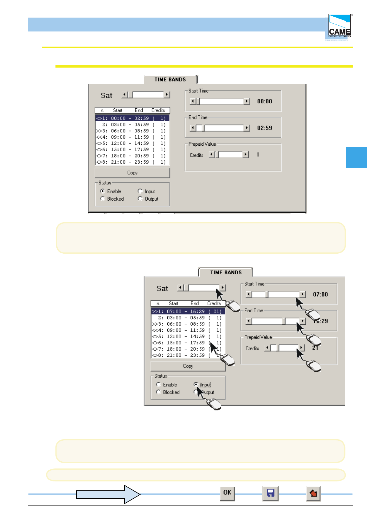
In the TIME BANDS dialog, up to 8 time bands may be set for every day of the
Note The default settings are: number of bands = 8; range of bands = 3 hours; prepaid value = 1 credit..
1- Select the day to set.
2- Select the time band to
change.
3- Set the time for the band to
start from
4- Set the time for the band to
end at
5- Assign a value to the band..
6- Select the band status:
ENABLED: both
entry and exit are permitted;
ENTRY: entry only is permitted
BLOCKED: neither
access nor exit
are permitted;
EXIT; exit only
is permitted.
week with the relative prepaid value.
1
3
4
2
5
6
the [COPY] button copies the settings for every day of the week;
Note:The bands not used must be neutralised by selecting ‘blocked’.
Caution! at the end of every group of opera tions, you must update to make the changes effective
to adjourn
ENGLISCH
cap. < 3 > pag. < 5 >
Page 42

Software - CONFIGURATION TIMINGS
RBM 84 -Software
Confi guration dialog of Blocked and Free Days
In the BLOCKED DAYS dialog, you can set blocked or closed days (max. 60) as well as part days for
any day of the year.
The Blocked Days may be cancelled using the [CANCEL] button or temporarily freed by
selectingClear: the latter option allows unrestricted access and Credits subtracted from the users.
Cap 3
B=Blocked
L=Free
1
1- Click on the NEW key
2- Select the month of the day to block
3- Select the day to block (the day on which access is not ermitted)
4- Set the time for the block to start at
5- Set the time for the block to end
6- Select whether to BLOCK or FREE access
2
3
4
5
6
N.B. On BLOCKED days, whoever is inside the car park can still leave.
N.B. On FREE days, the enabled card holders enter free of charge even if the bands are blocked.
Attenzione! alla fi ne di ogni gruppo di operazioni bisogna aggiornare, per rendere operative le modifi che
Aggiornare
ENGLISCH
cap. < 3 > pag. < 6 >
Page 43

Software - CONFIGURATION TIMINGS
RBM 84 -Software
Confi guration dialog of Planned Openings and Antipassback
The planned openings, for instance at a production unit where staff mostly enter and
leave in two waves per working day, allow an exit to be set for once or
twice during the day, after which the system reverts to its planned access functions.
Bar for setting the Antipassback time limit
2
2- Click on the ‘new’ icon to display the confi guration rectangle.
1- Clicking on
the PLANNED
1
OPENINGS icon
Cap 3
activates the
confi guration
window
ENGLISCH
Close
Cancel
Apply
Changes
Confi guration
Rectangle
cap. < 3 > pag. < 7 >
Page 44

Software - CONFIGURATION TIMINGS
RBM 84 -Software
Confi guration dialog of the Planned Openings
3
3- Select the entrance
to activate.
Cap 3
4- Set the opening time
5- Set the closing time
4
5
6- Select the days
for it to open on
7- To ensure intervention takes place,
6
this must be enabled.
7
To have a setting applied to every day, simply click on ‘All’.
Next click on Apply Changes to update the newsettings..
Attenzione! alla fi ne di ogni gruppo di operazioni bisogna aggiornare, per rendere operative le modifi che
Aggiornare
ENGLISCH
cap. < 3 > pag. < 8 >
Page 45

S E C T I O N 4
RBM84 - SOFTWARE
CONFIGURATION
USERS
CONTENTS
subject page
General notes ............................................................................................................ 2
Users’ configuration window .................................................................................. 3
Registering a new user............................................................................................. 4
Saving the user code ................................................................................................ 6
Configurating ACCESS mode .................................................................................. 9
Normal access procedure ...................................................................................... 10
Prepaid access procedure...................................................................................... 11
Prepaid time-limit access procedure .................................................................... 13
Access validity ........................................................................................................ 14
Adding a given number of Users........................................................................... 15
Users’ status check ................................................................................................ 18
Page 46

Software - CONFIGURATION USERS
RBM 84 -Software
General notes
During User-Confi guration operations, we recommend you frequently save the selections made as this will
speed up the whole programming process (avoiding frequent checks and re-programming) and make it
safer.
You can use
the [UPDATE] button,
the
and the
[SAVE USERS] button
graphic button [WRITE USER IN RBM84]
, which must be pressed in the order described.
In the following pages we will indicate at which points it is critical to save data, with the following symbol:
to adjourn
Cap 4
ENGLISCH
cap. < 4 > pag. < 2 >
Page 47

Software - CONFIGURATION USERS
RBM 84 -Software
Users’ configuration window
13
1 2 3 4
Cap 4
14
1112
1 - Record dialog of the users’ personal data
2 - Dialog for saving user codes
3 - Configuration dialog of access procedures for each user (times, tariffs, restrictions etc.)
4 - Dialog for each user’s current situation
5 - Close button
6 - Read user from RBM84 button
7 - Write user to RBM84 button
8 - APB re-synchronisation button
9 - Save (on computer hard drive) button
10- Cancel button
11- OK (apply changes made) button
12- Field for searching User Name
13- User list window
14- Create new user key (the 4 dialogs are empty without at least one registered user).
ENGLISCH
10
6789
cap. < 4 > pag. < 3 >
5
Page 48

Software - CONFIGURATION USERS
RBM 84 -Software
Registering a NEW USER
In the REGISTER dialog, the user’s personal data such as name, addresses
and group may be recorded.
The [NEW SEQUENCE] key is used to generate “x” number of users having the same settings
(or command device: Keyboard, Remote Control or Card) as those of the last user generated
Cap 4
ENGLISCH
Click on [NEW] and the fi elds for adding personal data etc. will appear
cap. < 4 > pag. < 4 >
Page 49

Software - CONFIGURATION USERS
RBM 84 -Software
Registering a NEW USER
... key in the data required
The registration date appears
automatically
while all other data are optional
Cap 4
... click on [GROUP] key] ...
... select the group you
want to associate the user
to; then click [OK]
The [ALL] button
associates or
disassociates the user
to/from all the groups.
The default selection is
no association
ENGLISCH
It is compulsory to assign users to at least one User Group.
It is essential, though, in systems where there are several entrances used for different user categories
. A typical example is a company having entrances designated specifi cally to its offi ces, production
units, suppliers, etc. and where some users (e.g. surveillance or maintenance personnel) must be
allowed access through all of the entrances.
cap. < 4 > pag. < 5 >
Page 50

Software - CONFIGURATION USERS
RBM 84 -Software
Saving the USER CODE
The user code must be saved in the CODE dialog using a PC30 (or also
directly from the software for the keyboards).
Cap 4
In the Code Typepull-down menu,
select the command device you want to
save the code of ...
... click on the [NEW CODE] key...
The CHECK CODE] key is used to check whether a code saved or for reading the code of a given
device
ENGLISCH
cap. < 4 > pag. < 6 >
Page 51

Software - CONFIGURATION USERS
RBM 84 -Software
Saving the USER CODE
... and then, within 10 seconds,
A- for the TAM and ATOMO remote controls, press
the key to save, sending the signal to the dedicated
area on the front panel of PC30, or
B - for TSP00, move the proximity Card you
want to save to the dedicated area on the front
panel of PC30, or
Cap 4
C- for LT001, swipe the Card to save
along the dedicated groove on the
front panel of PC30.
For the S5000, S6000 and S7000 keyboards however, we are promted to indicate if we want to use
PC30 to save the code; if not, saving must be made by the software (see next page)
... by pressing [YES],
D- type the number code into the dedicated
keypad on the front panel of PC30 and then
type “E”"
ENGLISCH
The code-saving functions described above (A- sending the signal,
B- bringing the Card in proximity to the panel, C- swiping the Card or D- typing the code) must take
place within the time it takes (10”) for the graduated bar in the lower part of the main window to scroll
cap. < 4 > pag. < 7 >
Page 52

Software - CONFIGURATION USERS
RBM 84 -Software
Saving the USER CODE
by pressing [NO], ...
... the KEYCODE window opens, which allows for an
advanced management of the number code.
1- First, select the box relating to the
keypad model to encode (change the code’s digits)...
2A - Then type in the number code on the numbered keys
2B- or leave the software to generate a
random code by clicking on [RANDOM]
3- When fi nished, confi rm with [OK]
If there are several users, using the KEYCODE window
to generate/save a keyboard code ensures there are no
duplicate codes; once generated or typed, the code can
be cancelled and changed - either wholly or partly - using
the keys[C] orCE]..
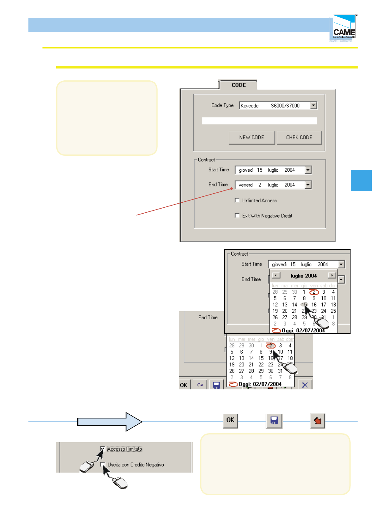
Access validity
1
Cap 4
2A
2B
3
To give unlimited access, i.e.
access with no expiry date,
tick the UNLIMITED ACCESS box;
by selecting also ‘Exit with Negative Credit’
, the user can leave even if s/he has
prepaid. S/he will have a negative credit.
If , however, a start date and end date are set,
the pass will carry a temporary validity.
to adjourn
ENGLISCH
cap. < 4 > pag. < 8 >
Page 53

Software - CONFIGURATION USERS
RBM 84 -Software
ACCESS procedure configurations
On the ACCESS sheet you can program different access procedures
for each user with or without tariffs.
In particular the following can be set for users:
- access type
- discount
- prepaid amount
- access tariff and validity
- time-band access
- Antipassback type
The default settings are: Access Type = NORMAL; Discount = NONE;
Prepaid = zero; Personalised access = Band group; Access Validity = ALWAYS; Access Tariff =
PREDEFINED; Antipassback Apb = DISABLED.
Cap 4
Setting the “bands” function
will apply the tariff set for
each time band.
Otherwise the time band
tariffs will be replaced by
the number set on this
section.
The default settings and, in particualr the NORMAL access type, are basically the
predefi ned settings for accesses in different paying car-park facilities where there is no need
to increase access tariffs but instead request all remaining management functions
(surveillance, access times, history print-out etc.)
ENGLISCH
cap. < 4 > pag. < 9 >
Page 54

Software - CONFIGURATION USERS
RBM 84 -Software
NORMAL access procedure
By leaving the default access as NORMAL, the Discount and
Prepaid areas are omitted.
Select the required access bands, for every day of the
week
The [ALL] button enables or disables all of the time bands.
If the time band appears red, this means it is blocked (for all
users) in Timings > Time Bands
A disabled time band hinders access; if the user is already
inside, the subtracted credits (as set in the following pages) will
be counted only for the PREPAID and PREPAID WITH TIME
LIMIT procedures
Cap 4
to adjourn
Antipassback
to adjourn
The bands change colour according to the
settings:
<> Black= entry/exit function
Red= Band Blocked
<< Blue= exit-only function
>> Brown= entry-only function
for every day
of the week
Select the type of AntiPassBack (not compulsory)
ENGLISCH
The AntiPassBack is used to stop the fraudulent use of the access devices, for example by allowing
more than one vehicle to enter or persons with only one Radio-control or Card.
AntiPassBack Time limit means that the user, after passing the entrance, cannot pass back again
across the entrance way for all the time of the antipassback defi ned in Timings > Time bands
AntiPassBack In/Out means that the user, after passing through the entrance, can only enter again
after having left through the normal exit.
cap. < 4 > pag. < 10 >
Page 55

Software - CONFIGURATION USERS
RBM 84 -Software
PREPAID access procedure
By selecting PREPAID access, it is
essential to defi ne the Prepaid area, whereas all the other areas are
optional (see Normal Access and Personalised Access for the access
validity)
The term “Prepaid” means a number of credits purchased by the user
having a value defi ned individually by each system manager (for example
1.20 Euro/dollar/pounds sterling/etc. for each credit): RBM84 does not
calculate in currency terms, but only in number of credits.
Set the user-purchased Credits, which will appear in the left-
hand box, ...
The left-hand box always represents the last purchase of Credits
by the user.
Cap 4
... and transfer them into the right-hand box with the button [>>]
The right-hand box instead represents the availability of Credits
the user still has (i.e. after already subtracting the already-”spent”
ones).
If, before “spending” all the credits, the user buys some more,
to add them, click on the button [+]
to adjourn
ENGLISCH
cap. < 4 > pag. < 11 >
Page 56

Software - CONFIGURATION USERS
RBM 84 -Software
PREPAID access procedure
You can now select two greatly different settings for counting the credits.
In the fi rst setting, which we will call PREPAID BY BANDS (USERS or GROUP),
you can leave the previously-defi ned credit settings. In this way, the count will vary depending on the
band and access day.
In the second, which we will call PREPAID BY ACCESS or TARIFF, you can vary the Number of
Credits applied in Individual Access. This setting will subtract only one credit amount for each
access irrespective of the time elapsed, time bands or access day.
No additional selection is necessary: RBM84 adds the number of credits of the entrance time band to
the numbers of credits of each timeband that begins during the period elapsed from entry until exit.
PREPAID BY TIME BANDS
Cap 4
EXAMPLEOF COUNT FOR PREPAID BY TIMEBANDS
A = time elapsed from
entry until exit
In this example, 10 + 15 + 20 credits will be subtracted from the user
PREPAID BY ACCESS OR TARIFF
By clicking on the Tariffs bar, you will disable the
payment by time bands as the tariff will take priority.
In the example, 3 credits will be given for each
band and the timebands’ set values will be ignored.
ENGLISCH
to adjourn
RBM84 will thus subtract a fi xed rate of 5 credits for each entry by the user.
cap. < 4 > pag. < 12 >
Page 57

Software - CONFIGURATION USERS
RBM 84 -Software
PREPAID WITH TIME-LIMIT access procedure
The PREPAID WITH TIME LIMITmode is similar to the PREPAID
mode and the areas to defi ne are the same (which we refer to you
for the selection details).
The only difference is the way of calculating the credits to charge the
user which, in this access type, is connected to a time interval (Time
associated to the Credit,not to be confused with time band).
to adjourn
Click on the Tariffs bar to set the number
of credits.
This procedure takes account of the set-up made
in the “tariffs” window: time associated to credit.
Cap 4
ENGLISCH
With the PREPAID WITH TIME LIMIT mode, RBM84 multiplies the number of credits set in Individual
Access, for each time interval associated to the credit, or fraction thereof, elapsing from
entrance until exit..
CALCULATION EXAMPLE FOR PREPAID WITH TIME
A = time elapsed from entry
until exit
B = time associated to the
Credit
in this case, 4 time intervals will be subtracted (no. credits applied) from the user.
cap. < 4 > pag. < 13 >
Page 58
RBM 84 -Software
Access validity
In the CODES dialog, for all
the three modes, you can
also set an access validity time
(subscription type) irrespective
of the credits purchased or
remaining; this validity can be
renewed at any time.
Software - CONFIGURATION USERS
Cap 4
The code validity
(discount ticket) ends at 24:00
on the day set
1- Set the contract start date
2- Set the contract end date
1
2
ENGLISCH
to adjourn
With UNLIMITED ACCESS, there is no longer a
contract expiry date. Instead, with EXIT WITH
NEGATIVE CREDIT the user can exit even if
he/she has fi nished the credits in his/her pass
(otherwise the user would not be able to leave),
and at the next recharge, the amount owed will be
signalled in red.
cap. < 4 > pag. < 14 >
Page 59

Software - CONFIGURATION USERS
RBM 84 -Software
Adding a GIVEN NUMBER OF USERS (New Sequence)
This procedure adds any number of users (up to the maximum number allowed by the system)
with the same characteristics of code type (Keyboard, Radio-control or Card), access type and group
belonging.
It is therefore necessary to confi gure a user with the desired characteristics, through the
PERSONALISED, CODE and ACCESS dialogs, so as to then return to PERSONALISED and start up
the procedure.
2
1
3
Cap 4
4
ENGLISCH
Click on [NEW(it is not necessary to complete the data in this phase) ...
... go to the CODE dialog and save a user code type ...
... go to the ACCESS dialog and save an access type ...
to adjourn
... then click on the [NEW SEQUENCE] button ...
If a new user is not saved, the procedure will repeat the last user entered (in the example
user 007), applying the same sensor type characteristics.
cap. < 4 > pag. < 15 >
Page 60

Software - CONFIGURATION USERS
RBM 84 -Software
Adding a GIVEN NUMBER OF USERS
select the number of users to add (10 users as default)
and run the procedure with the [START] button.
1
At this point, if the code type is a Keyboard ..
2
3
Cap 4
.
ENGLISCH
... the software will add them to the user list, generating a different random code for each one; click
the[END] button to terminate the procedure.
to adjourn
cap. < 4 > pag. < 16 >
Page 61

Software - CONFIGURATION USERS
RBM 84 -Software
Adding a GIVEN NUMBER OF USERS
... if the code type is instead a Transmitter or a Card:
...... after starting up the procedure ...
... you must save, through PC30, the respective
code for each device
Cap 4
Created !
For each generation of new user, the graduated bar
starts again while waiting for the next code.
... if the code being saved is already
present
... you must click [START] again and save a valid code. Click the [END]button to terminate the procedure.
ENGLISCH
This also applies when, for whatever reason, you don’t succeed in saving it within 10 seconds
to adjourn
cap. < 4 > pag. < 17 >
Page 62

RBM 84 -Software
USER STATUS check
The STATUS dialog gives the updated status of every user with reference to:
- the date and time of the last entry
- the date and time of the last exit
- the presence or absence of the user within the system
- the total length of stay within the system
- the total number of accesses made
- The number of remaining Credits
Software - CONFIGURATION USERS
Cap 4
Change the Current User
Status
Zeros the Total Length of
Stay counter
Zeros the Total Number of
Accesses counter
The Current Status (wheter present in the system) can be changed at any time and the Total Length
of Stay and Total Visits can also be zeroed using the relevant buttons
ENGLISCH
cap. < 4 > pag. < 18 >
Page 63
S E C T I O N 5
RBM84 - SOFTWARE
UPDATES
- DAILY HISTORY
CONTENTS
subject page
RBM84 Upgrades ...................................................................................................... 2
Display preferences .................................................................................................. 3
History Management .................................................................................................. 3
Events history ............................................................................................................ 4
Daily Management .................................................................................................... 6
Page 64

RBM 84 -Software
RBM84 Upgrades
The UPDATES dialog is used to update, simultaneously or individually, the three key sections of the
confi guration: System, Timings and Users.
Before starting up the update procedures, all the changes made
previously must be saved; to this end, we recommend pressing the buttons shown here, at least at the
end of every confi guration section indicated above.
to adjourn
Software - UPDATES - DAILY HISTORY
1
Cap 5
2
3
4
Tick the section to update and click on [UPDATE], then[YES] to confi rm the update
... and wait for the graduated bar
in the lower part of the main window to
scroll down; then click on the [END]button
5
ENGLISCH
cap. < 5 > pag. < 2 >
Page 65

RBM 84 -Software
Display preferences
History Management
Software - UPDATES - DAILY HISTORY
By selecting HISTORY USING SENSOR NAME or
HISTORY USING GATE NAME, we can change the
display of column4 and, if shown, select either the gate
name where the event happens or the sensor name.
Instead, by selecting DISABLE ASSEMBLY ERROR ,
the assembly error is not managed.
Clicking this button opens the “History” window.
13
12
1
2
3
4
5
Cap 5
11
10
1 - Event numbering column
2 - Event description column
3 - User display column
4 - Display column of the gate or sensor
involved in the event
5 - Event date and time column
6 - “Close” button
ENGLISCH
9 8 6
7 - “Export in EXCEL format” button.
8 - “Print” button.
9 - “New Search” button
10 - Box for selecting users to search
11 - Box for selecting the events to search
12 - Box for selecting interval end to search
13 - Box for selecting interval start to search
7
cap. < 5 > pag. < 3 >
Page 66

RBM 84 -Software
History (EVENTS)
Software - UPDATES - DAILY HISTORY
User entry means registered persons’ access USER ENTRY
User exit means registered persons’ exitUSER EXIT
INTERNAL PASSAGE
ERROR: PASSAGE
INTERNAL
UNKNOWN USER
USER WITHOUT
ASSEMBLY
SENSOR WITHOUT
ASSEMBLY
APB I/O
With Passage, a passage is notifi ed within the system, without
changing the APB status.
With Internal Passage Error, a passage on the internal
sensor is notifi ed without fi rst being entered in the system.
Unknown user means an attempted access of by someone not registered
in the system
If there is not at least one user group assigned, it will be impossible
to perform access
If during system-programming we forget to assign at least one group to
each sensor, the sensor will not function
Attempted access on blocked day.BLOCKED DAY
Attempted access with antipassback activated (the user still results as being
within the system)
Attempted access outside the contract times (expired pass).CONTRACT EXPIRED
Attempted access with red traffi c light and related absence of places.RED TRAFFIC LIGHT
Attempted access with group not enabled to given sensor (or area)WRONG GROUP
Cap 5
DISABLED
BAND
BAND
ERROR ON APB TIME
INSUFFICIENT CREDIT
MANUAL ENTRY
TIME
TIME
BLOCK
LOCAL
Attempted access user disabled from operatingUSER ACCESS
Attempted user access in time band not enabled ERROR ON TIME BAND
Attempted user access during entry time band not enabled ERROR ON ENTRY TIME
Attempted user access during time band not enabled at the exit ERROR ON EXIT TIME
Attempted access with antipassback, time limit still active (time period
not yet expired)
Attempted exit with insuffi cient credit (if not enabled at the exit
with negative credit)
Access openings by PCACTIVATION
Access openings through time programming ACTIVATION
Access closure through time programming(end of the planned opening)END ACTIVATION
System block by pushbutton that acts directly on RBM84
or on REM unit
ENGLISCH
Manual clearing of blocked system by external button.
END BLOCK
cap. < 5 > pag. < 4 >
Page 67

RBM 84 -Software
History (EVENTS)
Software - UPDATES - DAILY HISTORY
System block by the software.REMOTE BLOCK
System unblock/release by software.REMOTE UNBLOCK
Alarm activated by external pushbutton.MANUAL ALARM
Alarm shut-down activated by pushbutton.MANUAL ALARM RESET
CHANGE SYSTEM
This signals when a setting change is made
to the system (only visible if the Password has been inserted)
CHANGE ACCESS
This signals when a change to the system access procedures is made
(only visible if the Password has been inserted)
CHANGE PASSHOLDERS
This signals when a change to the management
of the passholders is made (only visible if the Password has been inserted)
This item signals activation of the RBM84 board’s internal passwordBOARD PASSWORD
ACTIVATION
This item signals activation of the RBM84 board’s internal passwordREMOVAL
PASSWORD BOARD
BEGIN COMMUNICATION
MODEM
END COMMUNICATION
MODEM
With this, it is worth noting the end of the connection by modem on
RBM84
Con questa voce si segnala la fi ne della connessione mediante modem su
RBM84
By selecting between the EVENTS and USERS we can fi ne-tune the search to reduce superfl uous data,
thus allowing the relevant information to be found..
Cap 5
ENGLISCH
cap. < 5 > pag. < 5 >
Page 68

RBM 84 -Software
Daily Management
Software - UPDATES - DAILY HISTORY
Clicking this button opens the “Daily History” window.
11
1
2
3
4
5
Cap 5
10
9
1 - Column of event numbering
2 - Column of event description.
3 - Acting carrier display column
4 - Column for displaying the gate involved
in the event
5 - Column with the event’s date and time.
6 - “ Close” button
The EVENTS and USERS items are the same as those described on pages 4 and 5.
8 7 6
7 - “Print” button
8 - “New Search” button
9 - Box for selecting the users to search
10 - Box for selecting the events to search
11 - Box for selecting the data to search
12 - “Export”button
12
ENGLISCH
cap. < 5 > pag. < 6 >
Page 69

SECTION 6
RBM84 - SOFTWARE
PRINTS
CONTENTS
subject pag
Print window .............................................................................................................. 2
Print preview window................................................................................................... 3
Print preview window................................................................................................... 4
Project ManagementWindow ..................................................................................... 4
Page 70

RBM 84 -Software
PRINT window
7
Software - STAMPE
Clicking on this button will open the “Prints” window”.
1
6
5
1 - Upper margin may be set for headed sheets
2 - Printer currently set
3 - “Confi rmation” button
2
Cap 6
3
4
ITALIANO
4 - “Close” button
5 - “Print” button (fi rst look at the preview)
6 - Select the type of print to be completed (Register,Confi guration,History)
7 - Rows available for header (3 max.)
capitolo < 6 > pagina < 2 >
Page 71

Software - STAMPE
RBM 84 -Software
Print preview windows
1
2
Press the print button and a preview window depending on the type of print
requested will appear
Select the type
of data to
print.
User List
Cap 6
User
confi guration
before the
preview
you will be
asked to select
the user.
ITALIANO
capitolo < 6 > pagina < 3 >
Page 72

RBM 84 -Software
Print Preview Windows
Software - STAMPE
History
The history
before the
preview will
request the
period of
interest, and the
type of action.
Project Management
Clicking on this button will open the Project Management window that allows different
system confi gurations to be saved and loaded
Name of system currently
in use.
Path - where to fi nd the fi le.
If more than one project is
present, select which one to
leave for the next start up
Various saved projects can
be displayed
Cap 6
Save As button for current
project
Button for removing saved
projects.
ITALIANO
capitolo < 6 > pagina < 4 >
Page 73

SECT I O N 7
RBM84 - SOFTWARE
PASSWORD
CONTENTS
subject page
Adding the master password .................................................................................... 2
Changing the master password ................................................................................. 2
Adding the board password......................................................................................... 3
Access to password-protected board ......................................................................... 4
Adding users password .............................................................................................. 5
Page 74
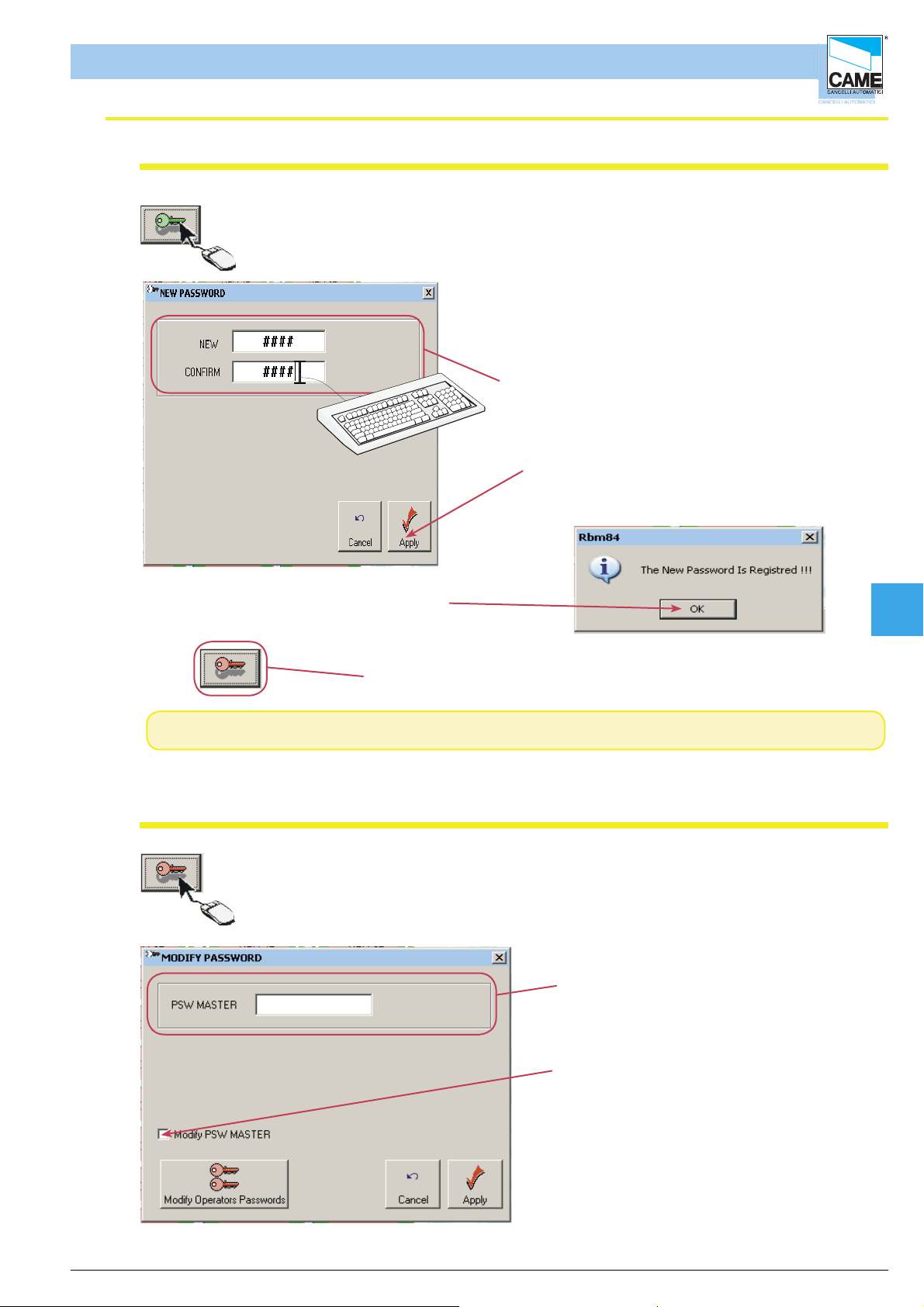
RBM 84 -Software
Adding master password
Software - PASSWORD
Clicking this button opens the window for keying in the password
In the “NEW” fi eld, type in the desired password
and then again in the “CONFIRM” fi eld to check
for any typing errors. This password is that of the
system administrator who manages the various
users.
Click OK to activate the changes.
Once the changes are made, the following
message will appea
When the password is active the key turns red
N.B. The program accepts alphanumeric passwords with a maximum of 8 characters
Change and deactivate master password
Clicking on the icon with the red key opens the Change
Password window where you can set the passwords for the users or
change that of the administrator and the board.
All changes require the administrator’s
password to be keyed in
Cap 7
ENGLISCH
To remove or change the main password, the
checkbox must be selected.
cap. < 7> pag. < 2 >
Page 75

Software - PASSWORD
RBM 84 -Software
Change and deactivate master password
As soon as selected, the checkbox opens a new panel as shown in the fi gure below.
All changes require the administrator’s
password to be keyed in
To remove the password, simply
fi ll in the two fi elds and click OK. To
change the administrator’s password
, simply write on “new” and again on
“confi rm” and then press OK.
RBM84 allows the
Password to be directly inserted in the board,
to test possible accesses via modem.
Adding board password
Clicking on this button opens the window for entering the board password
Tasto annulla.
Cap 7
Field for inserting the board password
Current status board password.
Current status administrator’s password.
Register button.
Once the board password is typed in and
confi rmed with the register button,
“password registered” will appear in the
window
This indicates the password is present on the board.
If the board and master passwords coincide, a single
icon
will appear. If, however, they are different, the icon will
appear along with a STOP icon
ENGLISCH
However, on the main screen
icons will appear
cap. < 7> pag. < 3 >
Page 76

Software - PASSWORD
RBM 84 -Software
Access to password-protected board
Clicking on this button opens the window for entering the board protection
password (when already activated)
This operation allows connection
of a password-protected RBM84, to
a PC with software which has no
password, or one different to that of the
board.
Cap 7
ENGLISCH
cap. < 7> pag. < 4 >
Page 77
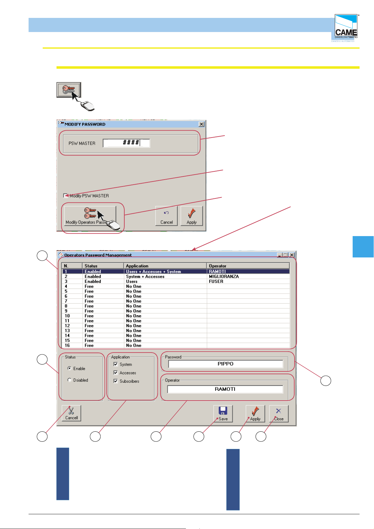
RBM 84 -Software
Adding users’ password
Software - PASSWORD
Once the master password is inserted, the users’ password may be entered.
Per fare qualsiasi modifi ca bisogna inserire la
password dell’aministratore (master)
To remove or change the main password,
you must select the checkbox.
Clicking on this button opens the window
for inserting the users’ password
1
Cap 7
2
9
3
ENGLISCH
4 5 6 7 8
1 - Summary window for managing the users’ passwords
2 - Selecting the user status
3 - Button for removing the users4
4 - Selecting authorisations to associate with the users
5 - Field for typing the user’s name
6 - Save button
7 - Apply Button
8 - Close Key
9 - Field for writing in the user’s password
cap. < 7> pag. < 5 >
Page 78
SECTION 8
RBM84 - SOFTWARE
MODEM
CONTENTS
subject page
Modem connection ..................................................................................................... 2
Connection with remote computer .............................................................................. 3
Remote connection window ....................................................................................... 4
Page 79

RBM 84 -Software
FUSE 630m A
123456789101112 0304050607 V1V2V3V4V5
CONTROL B OARD
PSIO1
TRANSFORMER TERMINAL BLOCK
LI NE FUSE 5A
CAME
U2
REM
REM PC 30
LT00 1
R501/2
S5000
S6000
S7000
DIGITA L INPUT
1
2
3
4
TSP00
LT00 1
S5000
S6000
S7000
TSP00
R501/2
Modem connection
Software - MODEM
RBM84
N.B. The telephone number
inserted for carrying out the
dial-up connection is that of the
modem connected to RBM84
1
1
ABS1
ABS1GNDOU
ABC
Y
R
BATTE
ER
TT
A
B
L N
L
RBM 8 Software
Cavo RS232
DEM
MO
ABGND
NO CNC
ABGND
OUT8
ODEM
M
Porta Modem
2
3
4
3
4
00
R800
R800
R800
-
-
700
R700
R
R700 -R 800
R700 -R 8002R
OUT
T
NC N O C
ABGND
OUT1
ABS1
ABS1GNDOU
GND
D
B
N1
GER
R
A
H
C
Y
N
700 -R800
R700 -
NONC C
ABGND
OUT2
R8
0-
R70
R700 -R 800
GND
OUT
T
NO CNC
ABGND
OUT3
P1
ABGND
OUT4
1345
2
ON
P2 P3 P4 Com Com
P5
P6 P7 P8
NO CNC
NO CNC
ABGND
OUT5
NO CNC
ABGND
OUT6
ABGND
ABGND
NO CNC
ABGND
OUT7
MODEM
Cap 8
CONTROLLO
ACCESSI
MODEM
telephone
line
COMPUTER for
remote control
ENGLISCH
Communication happens between a PC, its modem, the modem receiver and RBM84. During the
connection, it is possible to change any indicator and read any information.
N.B. Only modems equal to 56k can be used
cap.< 8> pag. < 2 >
Page 80

RBM 84 -Software
Remote computer connection
Software - MODEM
1- Enter in confi guration PC 30
1
2-to select the modem
2
Cap 8
3-confi rm
3
4-activate the remote connection window
ENGLISCH
4
cap.< 8> pag. < 3 >
Page 81
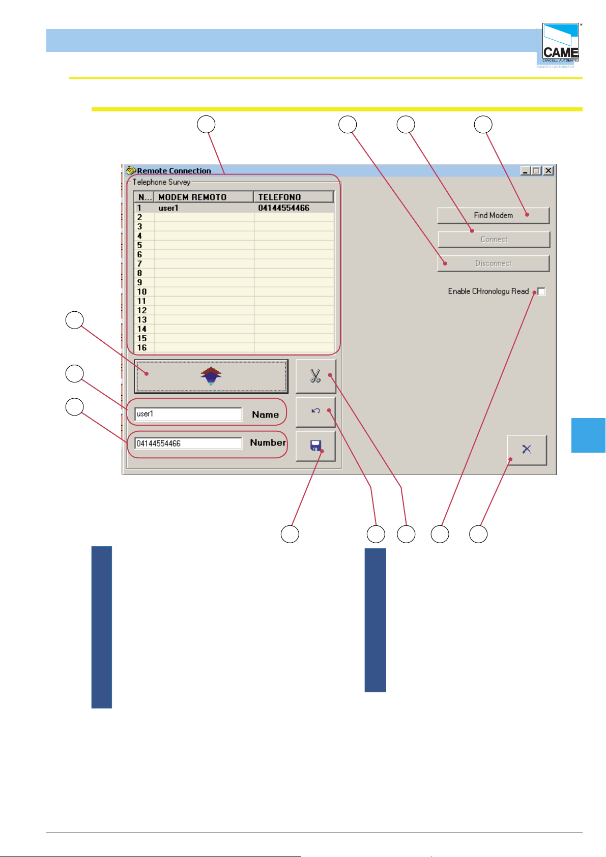
RBM 84 -Software
Remote connection window
Software - MODEM
12
11
10
1
432
6 5789
1 - Window displaying numbers column
2 - Disconnection button
3 - Connection button
4 - Button for detecting the installed modem and the
related connection port.
5 - Escape button
6 - Selection for activating the reading of the system
history through remote connection.
7 - Cancel user button
8 - Cancel operations button
9 - Save button
10- Field for entering telephone number
11- Field for entering remote modem name
(compulsory)
12- Button for entering numbers and names
Once the remote connection window is activated
- assign a number and a name to the remote modem
- have the system detect the modem (the modem detected is the one connected to our PC)
- save the changes
-Start the dial-up connection by pressing Connect
Cap 8
- once connected the remote connection window can be closed and the RBM84 used
ENGLISCH
cap.< 8> pag. < 4 >
 Loading...