

Page 1
SERIE TCA | TCA SERIES | SÉRIE TCA | BAUREIHE TCA | SERIE TCA | SERIE TCA
Documentazione
Tecnica
T34
rev. 01
02/2004
©
CAME
CANCELLI
RBM 21
CANCELLI AUTOMATICI
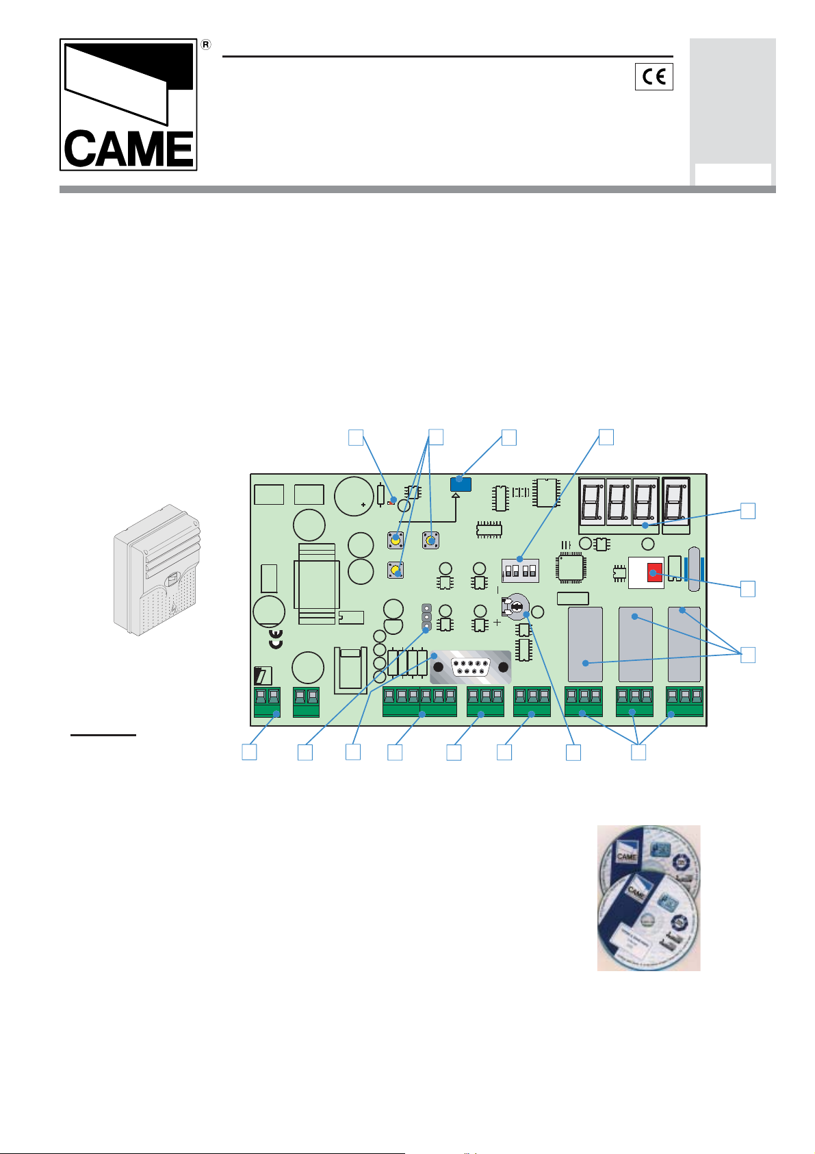
RBM21 is a control system for the simplified management of entries.
Offers the possibility of programming in Stand Alone (directly on the card) mode or On Line by
connecting it to a personal computer and installing the dedicated CAME software (compatible with
Windows 9x systems).
In the Stand Alone mode it is only possible to programme the basic functions of RBM21, such as the
addition and the deletion of Cards for normal access. But in the On Line mode it is possible to also
programme the system for
prepaid
(individual use of the Card) and
access; this mode also allows activating a
can indicate when available credit runs out.
(number of entries),
Timed AntipassBack
traffic light system by
timed credit
(amount of time),
(entries authorised at timed intervals) types of
programming an entries count that
AUTOMATICI
119R734-GB
AntipassBack
L1T L2T 24 0
CONTROL
BOARD
03 04 05 06 07
V1 V2 V3 V4 V5
FUSE 1A
E
M
A
C
1 2 3 4 5 6 7 8 9 10 11 12
LINE FUSE 1A
VOLTAGE OUTPUT
FUSE 630mA
RBM21
CAME
24V AC
L N
LEGEND
01 Sensory clamps
3
VOLTAGE OUTPUT
10
02 clamps Gone out relay
03 clamps feeding
04 keys planning
05 Display works
06 door RS 232 max 5mt.
07 door RS 485 max 1000 mt.
08 Trimmers regulation time activation
gone out relay 2
09 sensor of Proximity on board
10 Strip selection sensor on
board
11 relays (contact and exit
you go out semaphore)
12 Dip Switch works
13 card Memory Roll
14 Leds feeding files
15 clamps magnetic Coilsg
14
+
+
6
4
+
PROXIMITY CARD
CH1
CH2
ENTER
3
+
2
1
++ ++
S1 S2 GND S3 S4 GND
1
15
+
P1 P2 GND
9
O
12
N
TEMP
7
34
GND
12
5
A B
U1
+
Nc No C Nc No CAB
OUT1
8
MEMORY
Nc No C
OUT2
2
ROLL
RL3RL1 RL2
TRAFFIC LIGHT
13
11
Page 2
-
CONTENTS
Technical Specifications § 1.0 - pg. 2
Display messages § 1.1 - pg. 2
Dip-Switch functions § 1.2 - pg. 2
On-board sensor § 1.3 - pg. 2
Connections § 1.4 - pg. 3
Saving the 1
Saving of Cards § 2.1 - pg. 5
Creation of 2
Deletion of Cards § 2.3 - pg. 6
Changing the Password § 2.4 - pg. 7
TOTAL deletion of Cards § 2.5 - pg. 7
Using the Password to save Cards § 2.6 - pg. 8
Using the Password with the other procedures § 2.7 - pg. 8
ENGLISH
Data saving § 2.8 - pg. 9
Data restoration § 2.9 - pg. 9
Management through coils and diversified unloading § 3.0 - pg. 10
Software Installation § 3.1 - pg. 11
st
Card (Master Card) § 2.0 - pg. 4
nd
Master Card § 2.2 - pg. 6
1.0
Technical Specifications
- Power supply: 230V ac
- Absorption: 230V = 50 mA
- Relay outputs: 3
- Traffic light output: 1
- RS 232 port for PC connection (5 m
max distance)
- RS 485 port for PC connection (max.
1000 m distance, with PC40 interface)
- Extractable-connection terminal boards
- Number of Cards that can be saved: 500
proximity Cards and/or strip (magnetic)
Cards
- Programming: with Master Card or
Pass word in stand-alone mode; via
software in on-line mode
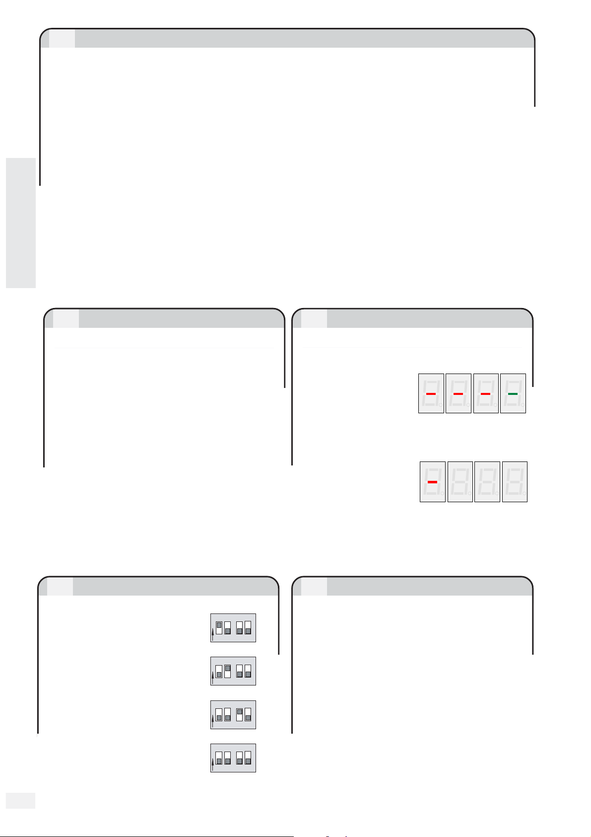
Dip-Switch functions
1.1
Display messages
When powering
the RBM21, if the
memory is
completely empty ,
all the central segments of the display
will come on.
If there are
memory
allocations already
assigned, a hyphen will appear on the
left display screen.
It also indicates the Stand-By position.
1.31.2
On-Board sensor
DIP 1 ON
Management of the
semaphore through coil
DIP 2 ON
N
O
N
12
34
34
It is a proximity sensor incorporated in the
board.
It emulates reader 4 and it saves Cards
(only proximity cards) directly on the
board in case the readers are far awa y.
O
12
diversified unloading
Activate it (and disactivate it when sa ving
DIP 3 ON
34
N
is over) with the selection strip, see pg. 3.
O
12
relay 1 stepper function
O
12
DIP 3 OF
relay 1
DIP 4
]
[
2
monostable
No Function
34
N
Page 3
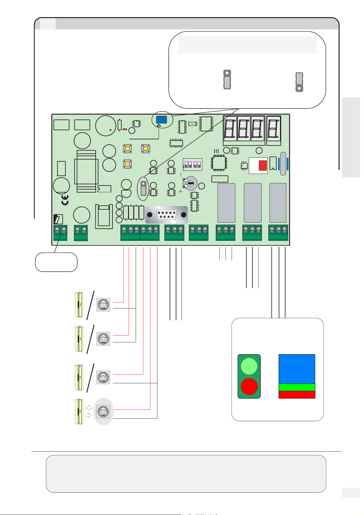
1.4
Connections
ON-BOARD SENSOR SELECTION
L1T L2T 24 0
CONTROL
BOARD
03 04 05 06 07
V1 V2 V3 V4 V5
FUSE 1A
1 2 3 4 5 6 7 8 9 10 11 12
LINE FUSE 1A
VOLTAGE OUTPUT
FUSE 630mA
RBM21
CAME
L N
24V AC
VOLTAGE OUTPUT
+
+
++ ++
S1 S2 GND S3 S4 GND
+
PROXIMITY CARD
CH1
ENTER
Jumpers
1 and 2
enable
reader 4
3
2
1
(default)
CH2
O
12
34
N
3
+
+
2
1
TEMP
U1
+
S4-IN
S4
A B
Jumpers
2 and 3
enable
On-Board
sensor
ROLL
MEMORY
RL3RL1 RL2
3
S4-IN
2
S4
1
Adjustment
Timing
ENGLISH
Relay 2 (RL2)
from 1 to 5 min.
P1 P2 GND
GND
Nc No C Nc No CAB
OUT1
Nc No C
OUT2
TRAFFIC LIGHT
Power supply
230V ac
Reader 1
ENTRY
Reader 2
ENTRY
Reader 3
EXIT
Reader 4
EXIT
MAGNETIC
CARD
PROXIMITY
CARD
Red
Red
Black
Red
Entry contacts
magnetic Coil
Red
Black
Output Contact Relay 1
max. 10A - 230V
(RL1)
Output Contact Relay 2
(RL2) max. 10A - 230V
Output Contact Relay 3 (RL3)
TRAFFIC LIGHT
max. 5A - 230V
P
LIBERO
COMPLETO
LIBERO
CLEAR
FULL
Can only be activated in
On-Line mode
THE FOLLOWING PAGES ILLUSTRATE ALL THE OPERATIONS THAT CAN BE CARRIED OUT IN STAND-ALONE
WITH PROXIMITY SENSORS; THE SAME INSTRUCTIONS CAN BE FOLLOWED FOR STRIP READERS WITH
MODE
WARNING THAT, WHERE IT IS INSTRUCTED TO "
THE
SWIPE
OR
SLIDE
TO
FOR INSTRUCTIONS IN ON-LINE MODE, PLEASE CONSULT THE CAME SOFTWARE.
THE CARD ACROSS THE READER.
FEED
", "
POSITION
", "
SWIPE
" OR "
SLIDE
", IT IS NECESSARY
[
]
3
Page 4
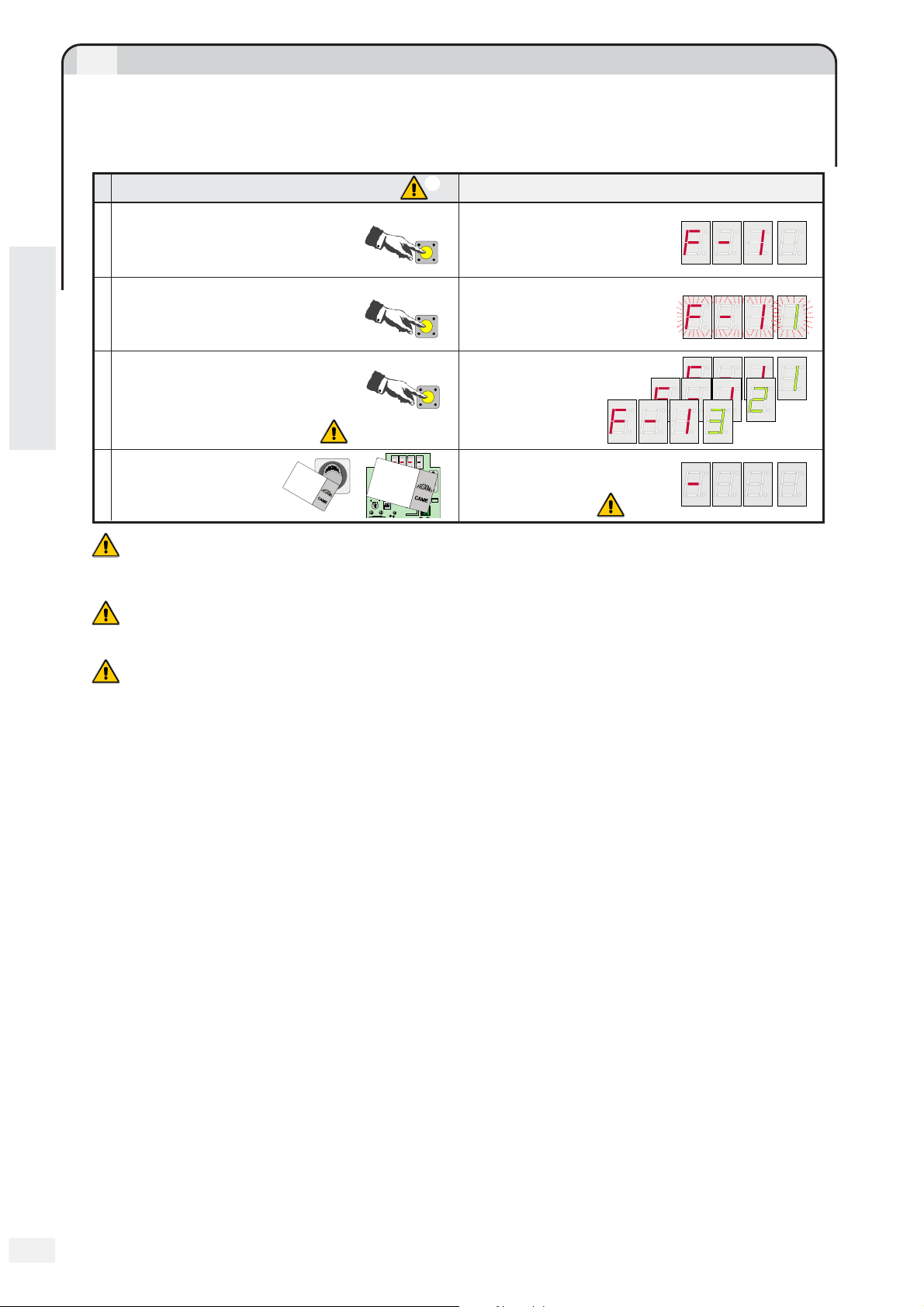
2.0
Saving the 1st Card (Master Card)
Rbm21 always assigns the first Card saved the role of Master Card, with which it is
possible to carry out all subsequent operations described here. It is therefore necessary to
keep it safe because, along with the Memory Roll card, it is essential in order to make any
Card programme changes or resets.
A
B
ENGLISH
C
D
ENTER
1
Display F - 1
SEQUENCE OF THE OPERATIONS INDICATIONS ON THE DISPLAY SCREEN
Press ENTER
Press ENTER again F - 1 1 flashes
ENTER
To change the relay to be con-
trolled, click CH1 once or
CH1
Change the relay asso-
ciated to the Master Card
twice, otherwise move on to
the next operation
Bring the Master Card
close to the sensor for
M
A
S
2 seconds
1
In this sequence, as in all subsequent sequences, if more than 10 seconds lapse between one operation
2
C
S4-IN
ENTER
a
r
d
0
1
CH1
PROXIMITY CARD
T
E
R
M
A
S
T
E
R
CH2
MEMORY ROLL
TEMP
CAME
O
12
N
The Stand By symbol appears
RS232
to indicate that the Master Card
is being saved
RS485
Gnd AB
3
and the next, Rbm21 returns to the Stand By position and it is necessary to recommence the
procedure from the start.
2
Rbm21 assigns relay 1 as default; the number 3 indicates the activation of both relays, not
the traffic light relay.
The saving of the Card is also always signaled by the flashing of the green and red LED indicators on
3
the front panel of the sensor.
]
[
4
Page 5

2.1
Saving of Cards
1
Once the Master Card has been saved,
all the other Cards can be saved with the On-Boar d sensor (see par . 1.3, page 2) ...
SEQUENCE OF THE OPERATIONS INDICATIONS ON THE DISPLAY SCREEN
Bring the Master Card
close to the on-board
A
sensor twice
To change the relay to be
controlled, click CH1 once
or twice, otherwise move on
B
to the next operation
C
S4-IN
ENTER
a
r
d
0
1
CH1
PROXIMITY CARD
M
A
S
T
E
R
CH2
MEMORY ROLL
TEMP
CAME
O
12
N
C
S4-IN
ENTER
a
r
d
0
1
CH1
RS232
AB
RS485
Gnd
PROXIMITY CARD
M
A
S
T
E
R
CH2
MEMORY ROLL
TEMP
CAME
O
12
N
CH1
after the position of the Master
RS232
Card (001), the first available
position flashes
AB
RS485
Gnd
Change the relay
associated to the
available position
relay 1
relay 2
relay 1+2
Bring the Card to be saved
close to the sensor for approximately 3 seconds
C
S4-IN
ENTER
CH1
C
PROXIMITY CARD
a
r
d
CH2
MEMORY ROLL
TEMP
CAME
O
12
N
When the Card is saved S t o
appears…
RS232
AB
RS485
Gnd
... and then the next available
position flashes
At this point you may continue to save Cards (repeating the previous two operations) or allow 10 seconds
to lapse so that Rbm21 returns to the Stand By position
... or directly on TSP00, without physical access to the board (a faster procedure to add Cards,
but it does not allow the possibility of associating both relays to Cards).
ENGLISH
SEQUENCE
THE OPERATIONS
OF
Swipe the Master
Card in front of the
sensor twice within
3 seconds
C
A
a
M
A
S
To change the relay from 1 to 2 and
vice versa, bring the Master Card
B
close to the sensor a third time or
move on to the next operation
Expose the Card to be saved for
approximately 3 seconds
C
FLESHES
V =
SEQUENCE
OF
SENSOR LED
R =
1st exposure 2nd exposure
V1"V V V V V
2"
3"
C
r
d
0
1
T
E
R
a
r
d
0
1
M
A
S
T
E
R
for 10” it then flashes less frequently while waiting
for the relay change or for the saving of the Card
RELAY 1
V
V V V VV
10"
Relay 2 is recognizable by the greater duration of
C
a
r
d
0
1
M
A
S
T
E
R
the single green flash
V
RELAY 2
V VV V
10"
Three green flashes confirm the Card has been saved
C
a
r
d
V
V V
1,5"
At this point you may continue saving other Cards (by repeating the previous 2 operations) or allow 10
seconds to lapse until Rbm21 returns to the Stand By position (steady red LED indicator light)
1
There is no On-Board sensor for magnetic cards and so it is necessary to carry out the first procedure
only and with at least one LT001 sensor connected and close to the Rbm21 board (a
configuration that is also necessary for all the other procedures).
[
]
5
Page 6

2.2
Creation of 2nd Master Card
By using a card that has already been saved, a second Master Card can be created.
(N.B. RBM21 accepts only two Master Cards)
SEQUENCE OF THE OPERATIONS INDICATIONS ON THE DISPLAY SCREEN
Swipe the Master Card
A
Press ENTER Display F - 1
B
Press CH1
C
Press ENTER F - 2 flashes
D
Swipe the Card that will be
saved as the 2
E
2.3
Deletion of Cards
nd
Master
M
A
S
T
E
R
ENTER
CH 1
ENTER
Display F - 2
Once saving is over, the
C
A
R
D
0
1
display screen displays
F - 2 M steadily
It is possible to delete one or more Cards at any time.
SEQUENCE OF THE OPERATIONS INDICATIONS ON THE DISPLAY SCREEN
Swipe one of the Master Cards
A
Press ENTER Display F - 1
B
Press CH1 3 times
C
Press ENTER
D
Press CH1 or CH2 to
select the location to
E
be eliminated
CH 1
001-> 500-> 499-> ...
Press ENTER
F
M
A
S
T
E
R
ENTER
3x
001-> 002-> 003-> ...
CH 1
ENTER
CH 2
ENTER
Display F - 4
The first memory location
appears
The location to be eliminated
appears: number 5, for
example
Once the location is eliminated,
the entire display screen
flashes
5
6
7
5
Be careful not to
6
If the letter C flashes, it means that in that location there are no Cards saved.
7
Proceed with another Card to be eliminated or allow 10 seconds to lapse in order to begin a new
delete the main Master Card (position 001, always marked by 3 flashing points)
procedure.
Page 7

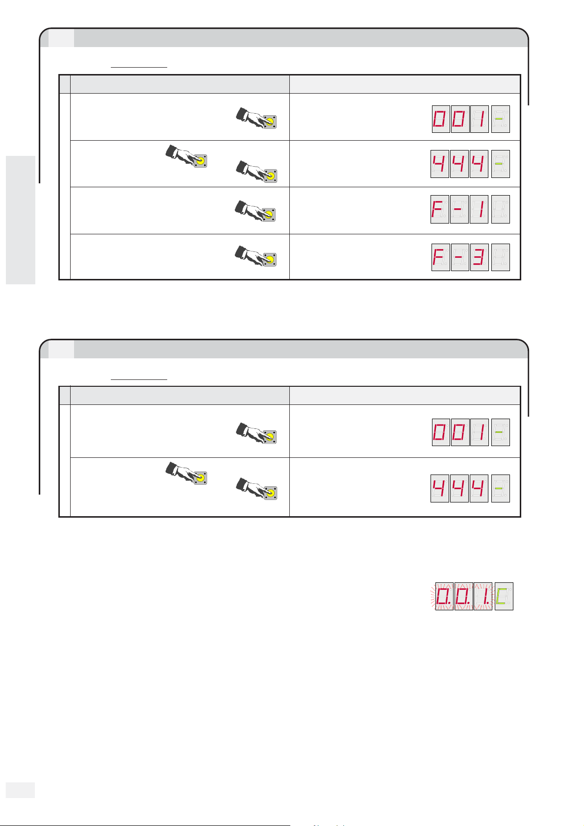
Changing the Password
2.4
Rbm21 comes with a Password that allows operating without the aid of the Master Card.
The default P assword is 1 2 3, and it can be changed to any number betw een 1 and 500 in the
following manner:
SEQUENCE OF THE OPERATIONS INDICATIONS ON THE DISPLAY SCREEN
Swipe the Master Card
A
Press ENTER Display F - 1
B
Press CH1 5 times
C
Press ENTER
D
Press CH1 or CH2
to select a new
E
Password
CH 1
001-> 500-> 499-> ...
Press ENTER
F
M
A
S
T
E
R
ENTER
5x
001-> 002-> 003-> ...
CH 1
ENTER
CH 2
ENTER
Display F - 6
The current Password
appears (the default
password in the example)
A new Password
appears, for example
4 4 4
The Stand By symbol appears to
indicate that the new Password
is being saved
Record the new Pass word here
so it will not be forgotten
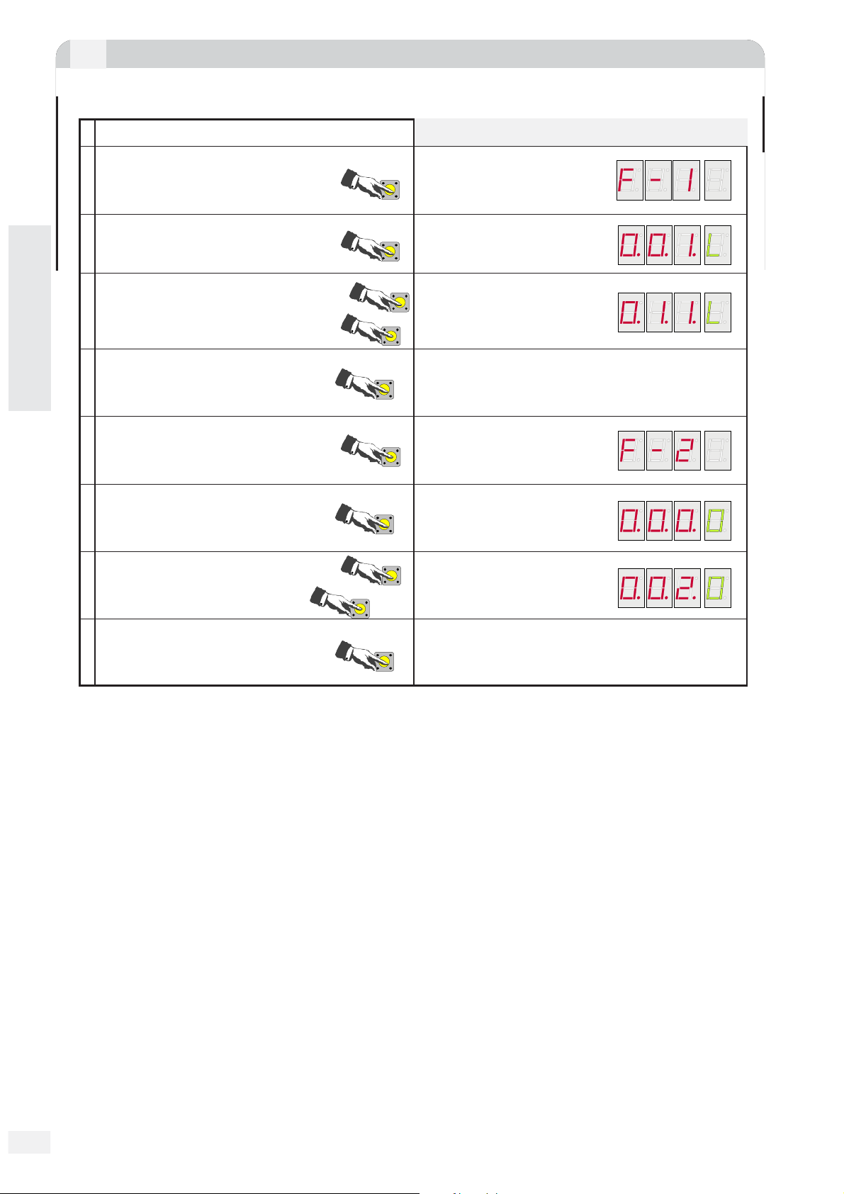
2.5
TOTAL deletion of Cards
This procedure resets the memory of Rbm21; all the Master Cards are deleted as well.
SEQUENCE OF THE OPERATIONS INDICATIONS ON THE DISPLAY SCREEN
Swipe one of the Master Cards
A
M
A
S
T
E
R
Press ENTER Display F - 1
B
Press CH1 4 times
C
Press ENTER and keep it
pressed for approximately 10
D
seconds
Release ENTER
E
4x
ENTER
CH1
ENTER
ENTER
Display F - 5
C L r A appears and flashes;
after 10 seconds the wording
stops flashing
An empty board symbol is
displayed
11
11
In order to be able to operate again with Rbm21 it is necessary to start from “Card Saving” in
§ 2.0.
Page 8
2.6
Using the Password to save Cards
Substitute operation A “swipe the Master Card twice” ... with this sequence
SEQUENCE OF THE OPERATIONS INDICATIONS ON THE DISPLAY SCREEN
ENGLISH
Press ENTER
Press CH1 or CH2 to
view the Password
Press ENTER
Substitute operation A
Press CH1 2 times
CH 1
001-> 002-> 003-> ...
001-> 500-> 499-> ...
2x
ENTER
CH 2
ENTER
CH 1
... and contin ue with the other operations illustrated in the
2.1 “Card Saving ” procedure in page 5
2.7
Using the Password with the other procedures
Substitute
operation A “s wipe the Master Card” ... with this sequence
The Password appears
Display F - 1
Display F - 3
SEQUENCE OF THE OPERATIONS INDICATIONS ON THE DISPLAY SCREEN
Press ENTER
ENTER
Press CH1 or CH2 to
view the Password
Substitute operation A
CH 1
001-> 002-> 003-> ...
001-> 500-> 499-> ...
The Password appears
CH 2
... and continue with the other operations illustrated in procedures
2.2 “Creation of 2nd Master Card“ in page 6,
2.3 “Card Deletion” in page 6,
2.4 “Change P assword” in page 7
2.5 “TO TAL Card Deletion” in page 7
2.8 “Saving data” in page 9
2.9 “Reset data” in page 9
]
[
8
Page 9

2.8
Data saving
This procedure allows saving the data stored in RBM21 by
transferring it to the MEMOR Y ROLL card.
In this procedure as well as the ne xt one, insert the Memory Roll in its
slot (see Fig.1).
Each time the Memory Roll is connected or disconnected it is
8
necessary to turn off the Rbm21‘s power supply.
SEQUENCE OF THE OPERATIONS INDICATIONS ON THE DISPLAY SCREEN
MEMORY ROLL
Fig.1
CAME
8
MEMORY ROLL
Swipe one of the Master Cards
A
M
A
S
T
E
R
Press ENTER Display F - 1
B
Press CH1 6 times
C
6x
Press ENTER Display F - 7 U
D
Release ENTER
E
ENTER
CH1
ENTER
ENTER
Display F - 7
The Stand By symbol
appears after a few
seconds
9
The waiting time depends on the amount of data up- or downloaded; Rbm21 goes into Stand
By mode when the procedure is over. Disconnect the power supply, remove the Memory Roll
and store it in a safe place.
2.9
Data restoration
10
ENGLISH
9
This procedure restores the data saved b y downloading it from the MEMOR Y ROLL card.
SEQUENCE OF THE OPERATIONS INDICATIONS ON THE DISPLAY SCREEN
Swipe one of the Master Cards
A
M
A
S
T
E
R
Press ENTER Display F - 1
B
Press CH1 7 times
C
7x
Press ENTER Display F - 8 d
D
Release ENTER
E
10
In case the Rbm21 board is replaced or the Master Card is deleted, to restore the data it is necessary to physically have the
ENTER
CH1
ENTER
ENTER
Display F - 8
The Stand By symbol
appears after a few
seconds
9
same Master Card saved on the Memory Roll (or the 2nd Master Card, in case the main one has been lost), and to preliminarily
carry out procedure § 2.0.
[
]
9
Page 10
3.0
Management parking lot
Car-park managed through in/out coils with full traffic light
(with Dip No. 1 on)
A
B
C
ENGLISH
D
E
F
OPERATIONS SEQUENCE
Press ENTER twice
x2
Press ENTER Display L
Press CH1 and CH2 to set
system capacity
Press ENTER
Press CH2
Press ENTER
ENTER
ENTER
CH 1
CH 2
ENTER
CH 2
ENTER
Display F - 1
The number of places
we want to set appears
Display F - 2
Display 0
INDICATIONS
ON
THE DISPLAY
Press CH1 and CH2 to set the
CH 1
G
number of occupied places
H
Press ENTER
CH 2
ENTER
If P1 is activated (contact-coil-etc.) the count is increased and the OUT 1 relay switchesIf P2 is activated
(contact-coil-etc.) The count is decreased and the OUT 2 relay switchesOnce the system's capacity is
reached, the Parking relay triggers and contact P1 is prevented, while contact to using P2 always remains
enabled.
]
[
10
Page 11

3.1
Software Installation
For operation in On Line mode (via PC) only, it is necessary to install the software (floppy disk
or Cd-Rom) included in the Rbm21 package; once installed, read the “Guide to Rbm21 on-line
programming” av ailable with the software (in .pdf file) to programme the system.
1
Fig. 2
A window that will update some
system files will appear. If you are using
floppy disks, you will be asked to insert the
following disks: insert them and confirm with
OK.
1
1
3
Fig. 1
Insert the 1st floppy disk (or the Cd-Rom) into
the dedicated drive; click on START in the Windows
toolbar, select RUN and enter
A:\SETUP
(with the Cd-Rom, replace
the A with the letter of your CD drive);
confirm the operation by clicking on
OK.
2
Fig. 3
Close all the programmes that are open and
click on OK to proceed.
ENGLISH
1
Fig. 4
By carrying on to the next window
4
you can choose where to instal the program
by clicking on "Change Directory", or click
on the icon for the default installation
(C:\PROGRAMS\RBM21).
An “installation completed” window will appear at the end of the procedure to confirm the end of the
operation: click on OK and restart the computer to apply the new settings.
[
]
11
Page 12

Rev. 0.1 - 02/2004 Bellotto Flavio
Prima stesura
CANCELLI AUTOMATICI
CAME CANCELLI AUTOMATICI S.P.A.
(+39) 0422 4940 (+39) 0422 4941
SSISTENZA TECNICA
A
NUMERO VERDE
800 295830
W
EB
www.came.it
E-
MAIL
info@came.it
DOSSON DI CASIER (TREVISO)
SISTEMA QUALITÀ
CERTIFICATO
CAME LOMBARDIA S.R.L.___COLOGNO M. (MI)
(+39) 02 26708293 (+39) 02 25490288
CAME SUD S.R.L. _________________NAPOLI
(+39) 081 7524455 (+39) 081 7529109
CAME (AMERICA) L.L.C._________MIAMI (FL)
(+1) 305 593 8798 (+1) 305 593 9823
CAME AUTOMATISMOS S.A_________MADRID
(+34) 091 5285009 (+34) 091 4685442
CAME BELGIUM NV-SA___________LESSINES
(+32) 068 333014 (+32) 068 338019
CAME FRANCE S.A.___NANTERRE CEDEX (PARIS)
(+33) 01 46130505 (+33) 01 46130500
CAME GMBH____KORNTAL BEI (STUTTGART)
(+49) 07 11839590 (+49) 07 118395925
CAME GMBH________SEEFELD BEI (BERLIN)
(+49) 03 33988390 (+49) 03 339885508
CAME PL SP.ZO.O_________WARSZAWA
(+48) 022 8365076 (+48) 022 8369920
CAME UNITED KINGDOM LTD___NOTTINGHAM
(+44) 01159 210430 (+44) 01159 210431
 Loading...