

Page 1
CANCELLI AUTOMATICI
SERIE ATOMO |
RICEVITORE ESTERNO
EXTERNAL RECEIVER
RECEPTEUR EXTERNE
EXTERNER EMPFÄNGER
RECEPTOR EXTERNO
ATOMO SERIES
| SÉRIE ATOMO |
BAUREIHE ATOMO
|
SERIE ATOMO
Documentazione
S71
rev. 2.0
11/2001
©
RBE4RC
R O L L I N G C O D E
CANCELLI
AUTOMATICI
119RS71-GB
Tecnica
CAME
GB
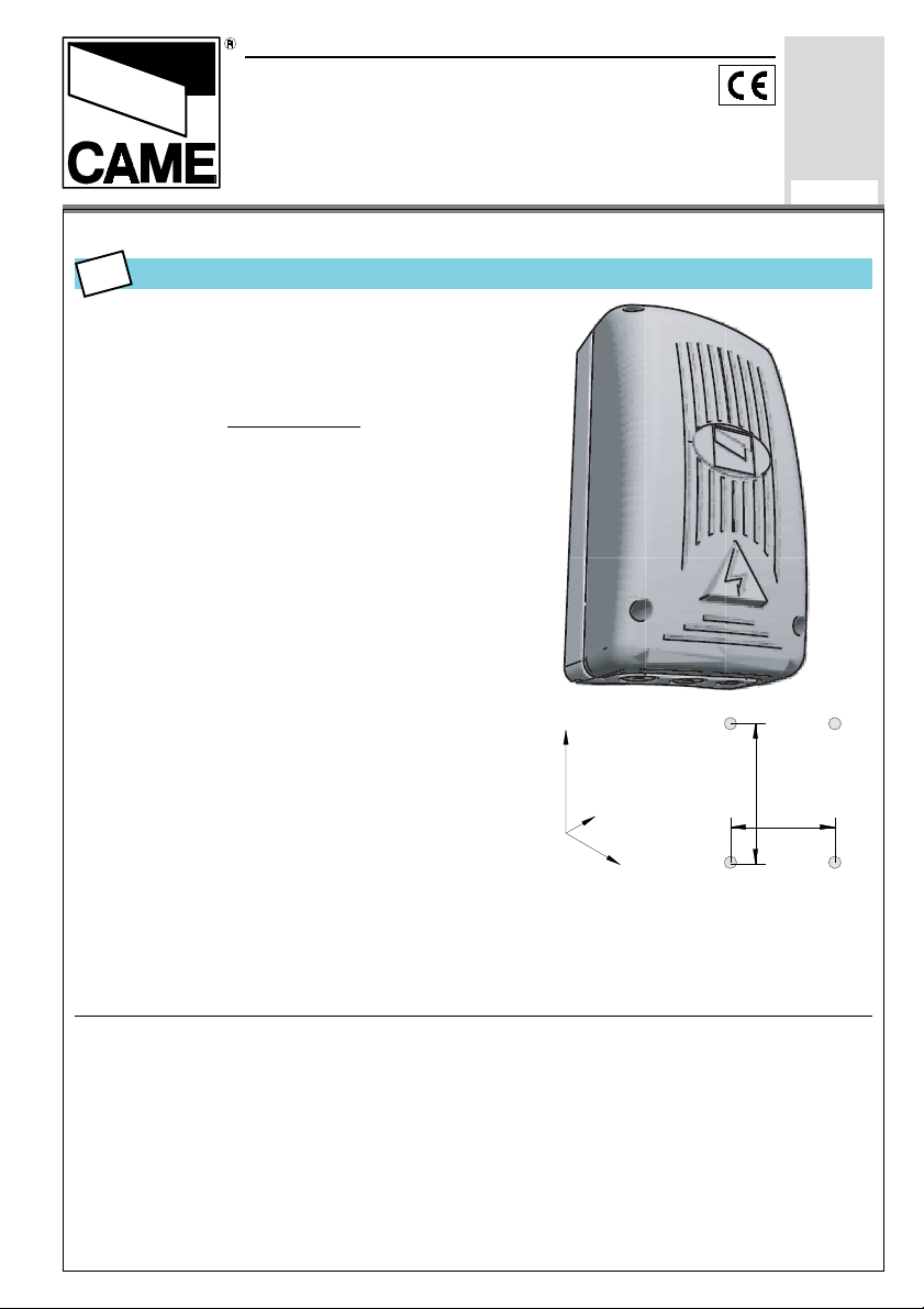
TECHNICAL SPECIFICATIONS
Four-channel AM 433.92 MHz frequency
Rolling Code Receiver, to be mounted on
the edge of the automation’s control board.
May be paired with ATOMO series CAME
transmitters with up to 500 units.
ABS outdoor container with IP54 protection
level.
Equipped with an internal display. Together
with Rolling Code technology, it allows quick
transmitter memorisation (max 500) and an
enduring, easy system maintenance (deleting/re-setting, adding or modifying)
It also includes a memory card (Memory Roll)
to make a back-up copy of all the memorised
transmitters.
N.B. All the operations of system programming and management may be carried out also by personal computer with
the related software.
The memory roll works with 12 or 24V AC/DC
Output functions:
- OUT1 in single stable or bistable mode
(see pg. 3)
- OUT2 in single stable mode with adjustable timing from 1 to 300 seconds (see pg.
3)
- OUT3 and 4 in normal single stable mode
224
87
104
180
75
"
N.B. – The receiver must always be equipped with an aerial.
- Do not install more than one receiver at a distance of less than 4-5 m from each other to avoid
function defects.
- It is a good idea to set the
aerial as high from the
ground as possible and far
from metallic structures and
in reinforced concrete.
Page 2

11
RBE4RC MOTHERBOARD
1 2 3 4
UP
DOWN
AB
ON
1234
OUT TEMP
1
2
3
ENGLISH
MEMORY ROLL
10
12V
0V
24V
AC/DC
9
RBE4RC
dis. 25883
NC NO C
OUT1
OUT2
MAIN COMPONENTS
1. Programming display
2. 4-way dipswitch
3. OUT2 relay adjustment trimmer
4. Re-set key
5. Memory Roll card connector
6. RS232 connector for connection to the PC
7. Antenna-connection terminal block
8. Devices-connection terminal boards to command
9. Terminal boards for 12/24V AC/DC power supply.
10. Memory Roll
11. Programming keys
CLEAR
OUT3 OUT4
4
5
6
7
8
-2-
Page 3

FUNCTION SELECTOR
ON
1234
1 and 2 Pprogramming and maintenance dips.
See pages ...
3 ON Bistable OUT1 relay
3 OFF Single stable OUT1 relay
4 Not used
TRIMMER ADJUSTMENT
ENGLISH
- MINIMUM single stable relay
activation time adjustment on output
OUT2: 1 second
- MAXIMUM single stable relay
activation time adjustment on output
OUT2: 300 seconds
PROGRAMMING/MAINTENANCE INDEX
- General notes -
PROG A - Memorises the 1
PROG B - Memorises subsequent transmitters
PROG C - Controls various outputs simultaneously
PROG D - Prepares a 2
PROG E - Changes password
PROG F - Saves the program on the Memory Roll
MANU A - Adds transmitters
MANU B - Deletes transmitters
MANU C - Inhibits a transmitter’s keys
MANU D - Deletes the entire programming
MANU E - Retrieves programming from the Memory Roll
read carefully
st
transmitter (TX Master)
nd
TX Master
pag. 4
pag. 5
pag. 6
pag. 7
pag. 8
pag. 9
pag. 10
pag. 11
pag. 12
pag. 13
pag. 14
pag. 15
-3-
Page 4

C
UP
1 3 42
DOWN
A
GENERAL NOTES
The first memorised transmitter will be automatically recognised by the card as the
Master transmitter (and inserted in the memory’s first location).
The TX Master will be the system’s main programming and maintenance “agent”. It is
therefore necessary that it be kept by the person in charge of the management of the
automation connected to the receiver.
To this purpose, the receiver set includes a red four-channel transmitter for the TX
Master’s use.
To facilitate the management of the system, at the end of the booklet there is a section
called “USER’S FILE” with a grid in which to write down the name of the user for each
transmitter; therefore please keep this booklet together with the TX Master.
ENGLISH
Viewer A shows the transmitter’s
numerical location in the receiver’s
memory (500 transmitters can be
memorised, including Masters); this
location unequivocally identifies
transmitters.
During maintenance/programming
operations, Viewer B indicates one of the
receiver’s four OUT outputs.
However, during normal operation it
indicates the transmitter channel/key.
Flashing means that no transmitter has
been memorised on that output.
NC NO C
0V
OUT1 OUT2
OUT3 OUT4
BA
Visors in stand by with
powered board
Flashing dots on the viewers means that the memory location has been reached for the
TX Master (the 1
st
is in location 001).
Additionally, the viewers guide the operator during the execution of the procedures
during programming/maintenance operations.
-4-
Page 5

C
UP
1 3 42
DOWN
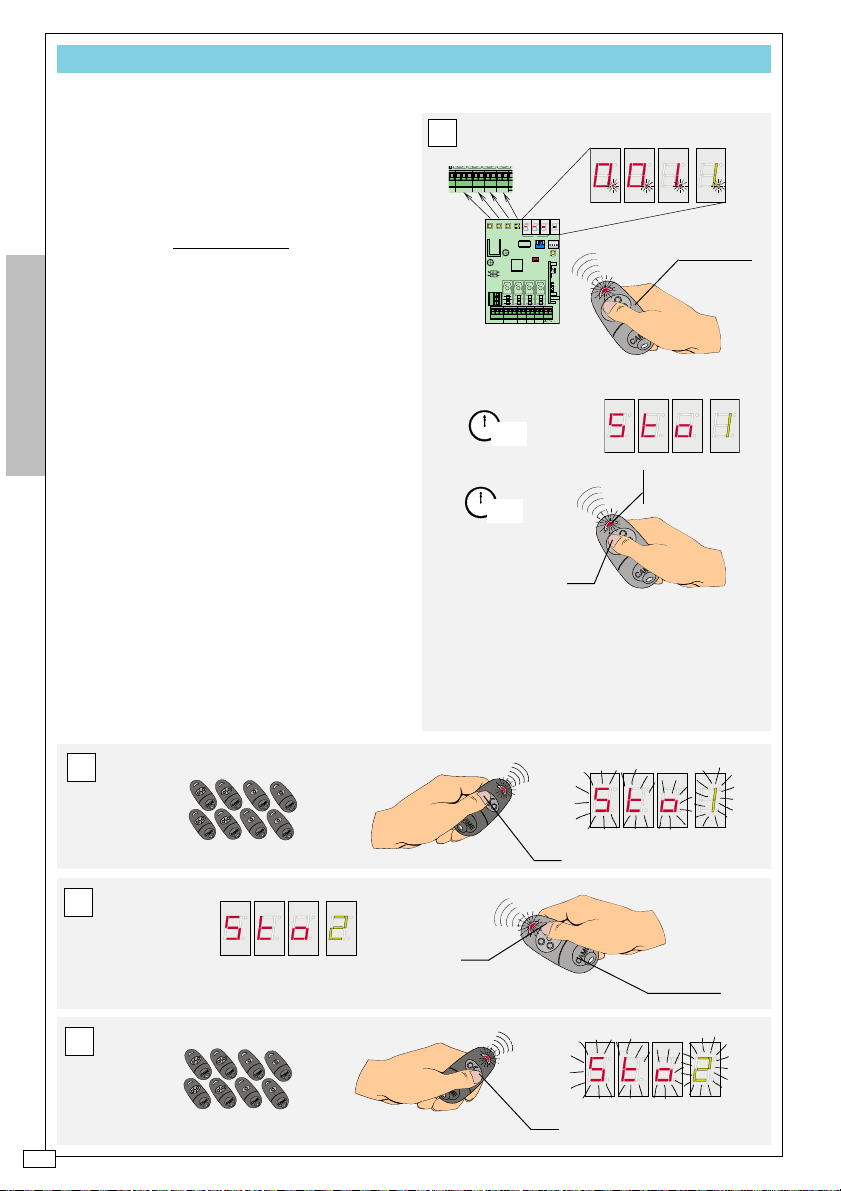
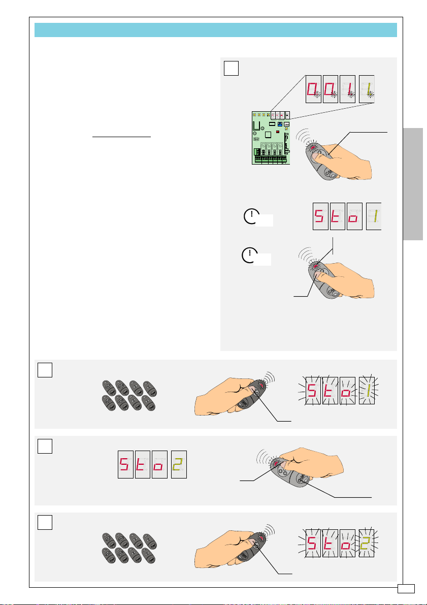
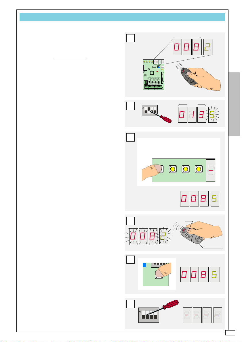
PROG A - Memorises the 1st transmitter (TX MASTER)
FIRST BASIC SYSTEM PROGRAMMING OPERATION.
THIS PROCEDURE ACTIVATES THE BOARD,
WHICH WOULD OTHERWISE REMAIN INACTIVE.
PROCEDURE
A Press the receiver’s button 1 until
|Sto|
appears on viewer A and output
|1|
on viewer B;
B press the Master transmitter’s P1
key until the messages disappear.
Repeat A and B for each of the receiver’s buttons and corresponding TX Master
buttons, that is, buttons 2, 3 and 4 respectively with keys P2, P3 and P4.
C Verify the TX Master ‘s programming by pressing its keys in sequence: the
succession of displays should coincide
with the one illustrated.
A
NC NO C
0V
OUT1 OUT2
OUT3 OUT4
ENGLISH
C
B
P1
P2
P3
P4
-5-
Page 6
C
PROG B - Memorises subsequent transmitters
AFTER MEMORISING THE TX MASTER, PREPARE
THE AVAILABLE SYSTEM TRANSMITTERS FOR
ALL
MEMORISATION. THE FOLLOWING PROCE-
QUICK
DURE IS ALSO VALID FOR SUBSEQUENT TRANSMIT-
TER ADDITIONS*
PROCEDURE
A Press the TX Master key for the
output that is to be activated (10”) until
|Sto|
+
|linked output number|
appears on
the viewers and (after another 5”) the
transmitter’s LED indicator remains with its
light on;
ENGLISH
B within 20”, press the corresponding
key on the memory transmitter: the messages on the viewers flash. Proceed this
way with all the memory transmitters for
that output.
C Press (within 20”) a new TX Master
key: the message changes, indicating the
new key/output on viewer B;
D repeat step B with the corresponding transmitter key.
* N.B. see also pg. II of the USER’S FILE
A
NCNOC0V
OUT1 OUT2
OUT3 OUT4
1 3 42
UP
DOWN
AB
ON
1234
9
10
10
9
11
OUT P.C.
12
11
6
12
1
6
_
TX RX
NC NO C0V12V24V
AC/DC
OUT1 OUT2
1
2
3
4578
10"
2
3
4578
15"
OUT TEMP
CLEAR
RBE4RC
OUT3 OUT4
P1
TX Master
LED indicator with
steady light on
B
P1
C
P2
TX Master
D
P2
-6-
Page 7
PROG C - Controls various outputs simultaneously
IF, FOR EXAMPLE, YOU WISH TO LINK THE SIMULTA-
NEOUS ACTIVATION OF THE FACILITIES CONNECTED
OUT1 AND OUT2 (LINKED SEPARATELY ON THE
TO
TX MASTER’S P1 AND P2 KEYS) TO A TRANSMIT-
TER’S P1 KEY, PLEASE PROCEED IN THE FOLLOW-
ING MANNER:
PROCEDURE
A Press the TX Master P1 key (10”)
|Sto|
+
|1|
until
appears on the viewer
and (after another 5”) the transmitter’s
LED indicator remains with its light on;
B within 20”, press the P1 key of the
transmitter to be memorised: the message on the viewer flashes. Proceed this
way with all the transmitters to be memorised for that output.
C Press (within 20”) the TX Master
P2 key: the message changes, indicating
|2|
key/output on viewer B
the
.
D repeat step B using the P1 key.
A
1 3 42
UP
DOWN
AB
ON
1234
10
9
11
10
9
11
_
OUT P.C.
TX RX
AC/DC
12
1
2
6
10"
12
1
2
3
4578
6
15"
OUT TEMP
CLEAR
RBE4RC
NC NO C0V12V24V
OUT1 OUT2
OUT3 OUT4
3
4578
P1
TX Master
ENGLISH
LED indicator with
steady light on
B
P1
C
P2
TX Master
D
P1
-7-
Page 8
UP
1 3 42
DOWN
PROG D - Prepares a 2nd TX MASTER
IF NECESSARY, IT IS POSSIBLE TO CONFIGURE ANY
THE ALREADY MEMORISED TRANSMITTERS AS A
OF
TX MASTER.
SECOND
PROCEDURE
A Press any key of the transmitter to
be configured as a second Master and
read the memory location occupied on
viewer A;
B set dip 2 to ON (viewer A shows the
first free memory location, viewer B a
|S|
flashing
ENGLISH
C select the transmitter location as
);
shown from point A with the UP and
DOWN keys;
D press any of the first TX Master’s
|M|
keys, (10”) until the
message, including periods, appears and flashes on
viewer B;
E re-set dip 2 to OFF.
N.B. It is possible to configure a single TX
Master in addition to the first one; if the
procedure is repeated with another TX, it
will automatically substitute the previous
one.
A
1 3 42
UP
DOWN
AB
ON
1234
OUT TEMP
CLEAR
_
OUT P.C.
TX RX
AC/DC
ON
B
1234
RBE4RC
NC NO C0V12V24V
OUT1 OUT2
OUT3 OUT4
ESEMPIO
C
UP=13/14/15...........499/500/1/2/3.....
DOWN=13/12/11.........3/2/1/500/499/...
ESEMPIO
-8-
D
E
1° TX Master
12
1
11
2
10
9
3
4578
6
10"
ON
1234
Page 9
CLEAR
1234
UT TEMP
CLEAR
1234
UT TEMP
UP
1 3 42
DOWN
3 4
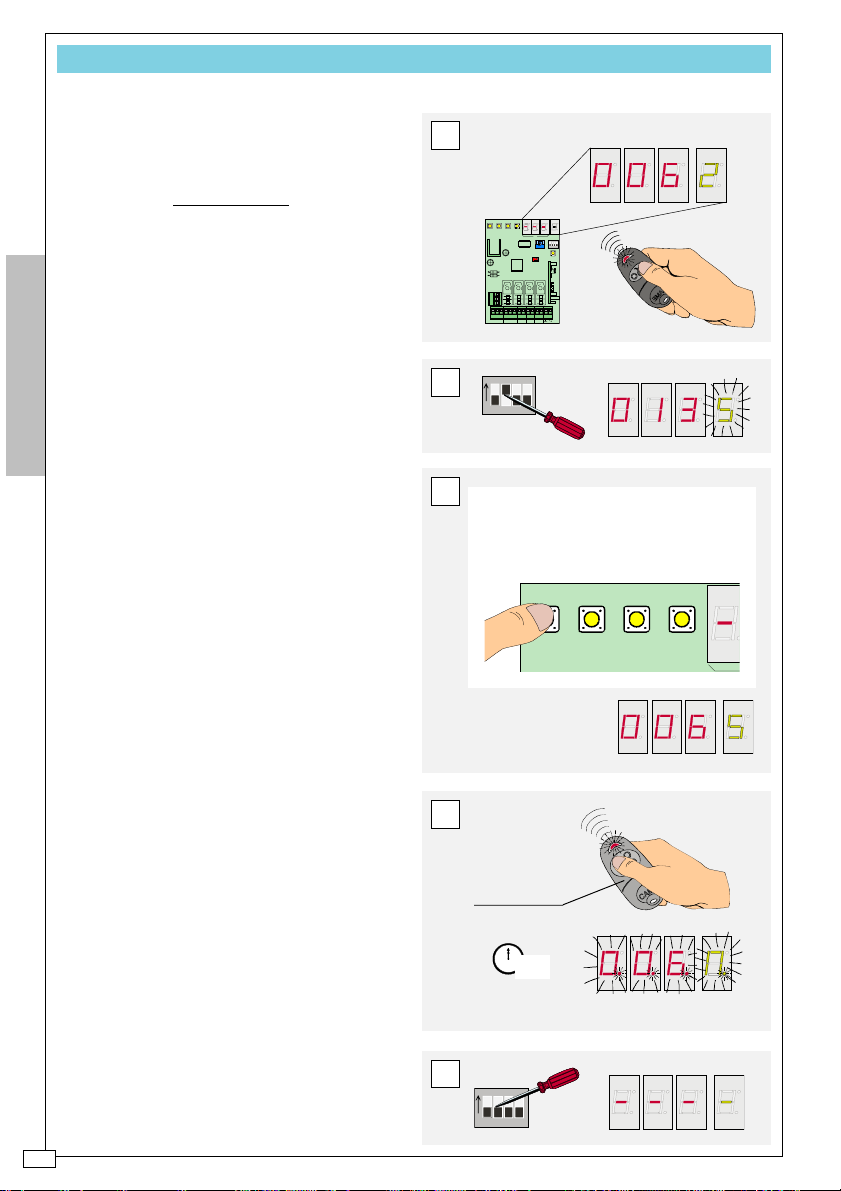
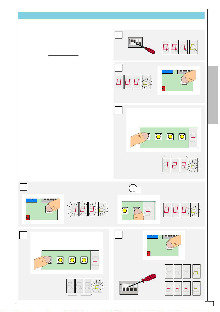
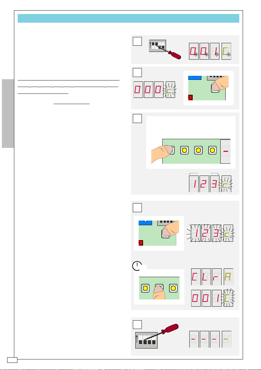
PROG E - Changes password
IF FOR ANY REASON IT BECOMES NECESSARY TO
-SET THE PROGRAMMING DONE (SEE MANU
RE
D),
THERE IS A SECURITY PASSWORD PRE-SET TO
123 BY CAME THAT CAN BE CUSTOMISED.
PROCEDURE
A Set dip 1 and 2 to ON:
|001| + |C|
appears on the viewers
B press the CLEAR key: the writing
changes to
|000| + |c|
and the “c” flashes);
C select the existing password (the
one pre-set , for example) with the UP and
DOWN keys;
D press the CLEAR key (the entire
message
|123| + |c|
flashes) and then,
within 5”, press key 4 (the message
changes to
|000| + |c|
and the “c” flashes);
E set the new password with the UP
and DOWN keys;
F press the CLEAR Key (the letter
|m|
appears without flashing on viewer B), and
re-set the dip 1 and 2 to OFF.
N.B. The new password can be made up
of a single digit. Copy it in the appropriate
space in the USER’S FILE
A
ON
1234
B
C
UP=13/14/15...........499/500/1/2/3.....
DOWN=13/12/11.........3/2/1/500/499/...
1,2,3 is the password
pre-set by CAME
ENGLISH
ESEMPIO
D
UT TEMP
E
UP=13/14/15...........499/500/1/2/3.....
DOWN=13/12/11.........3/2/1/500/499/...
select a new
password (a number
from 1 to 500)
1234
CLEAR
1 3 42
UP
DOWN
12
1
11
2
10
9
3
4578
6
5"
F
ON
A
1234
-9-
Page 10
UP
1 3 42
DOWN
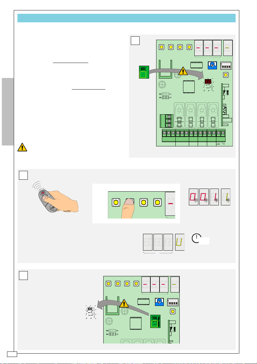
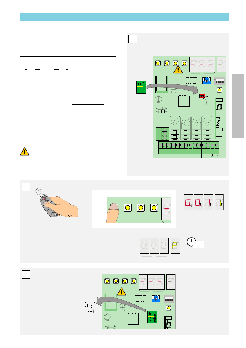
PROG F - Saves the program on the Memory Roll
UPON COMPLETION OF THE SYSTEM’S INSTALLA-
TION, USE THE MEMORY ROLL TO SAVE PROGRAM-
MING DONE ON THE RECEIVER.
PROCEDURE
A Insert (*) the Memory Roll in the
corresponding connector;
B first press and
keep pressed any
TX Master key and then key 2 on the receiver; release both only when (10”) the
|U|
message appears on viewer B;
C remove (*) the Memory Roll and file
ENGLISH
it.
* WARNING! Prior to any board connect-
ing or disconnecting operation, turn off the
power to the system.
B
BEFORE
A
AFTER
1 3 42
UP
DOWN
MEMORY ROLL
_
OUT P.C.
TX RX
NC NO C
12V
0V
24V
AC/DC
OUT1 OUT2
AB
ON
1234
OUT TEMP
CLEAR
OUT3 OUT4
RBE4RC
-10-
12
1
11
2
All 255 memory blocks transferred to the
Memory Roll scroll in quick succession on
viewer A
C
1 3 42
UP
DOWN
A
AB
ON
1234
OUT TEMP
CLEAR
10
9
3
4578
6
10"
RBE4RC
Page 11
UP
1 3 42
DOWN
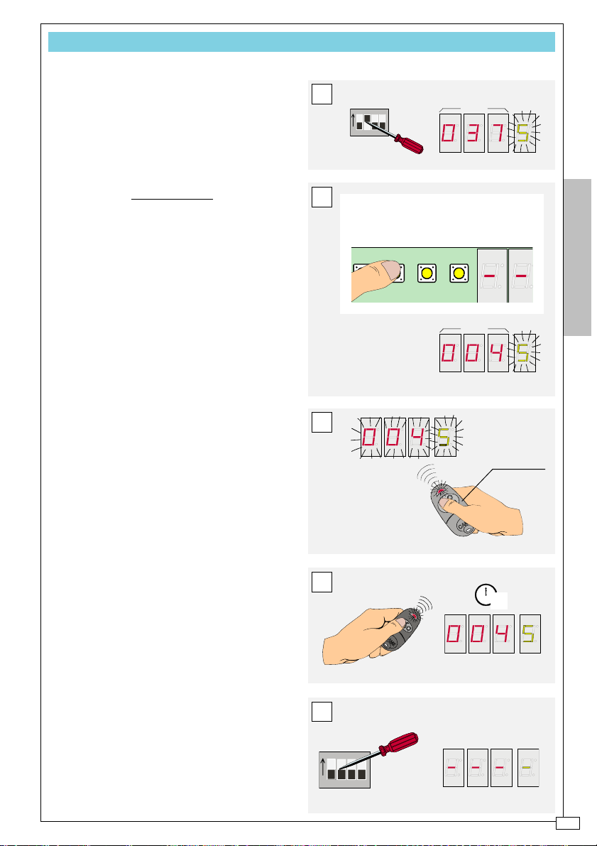
MANU A - Adds transmitters
THERE ARE TWO WAYS TO ADD TRANSMITTERS:
- ADD THEM IN SEQUENCE, THAT IS, MEMORISE
ON THE FIRST FREE* MEMORY LOCATION (SEE
THEM
PROG B)
- OR (THIS PROCEDURE) ADD THEM IN A CHOSEN
LOCATION.
FREE
PROCEDURE
A Set dip 2 to ON: the viewers indica-
te a flashing
|1st free location|
+
|S|
;
B select another free location where
to add the transmitter with the UP and
DOWN keys;
C press the TX Master key
corresponding to the output on which the
transmitter is to be added: the selected
location now flashes on the viewer;
D press (within 20”) the new
transmitter’s key: the writing on the viewer
will remain fixed after a few seconds;
E re-set dip 2 to OFF.
A
ON
1234
B
UP=13/14/15...........499/500/1/2/3.....
DOWN=13/12/11.........3/2/1/500/499/...
If the |S| does not flash, it
means that location is
already occupied
C
ESEMPIO
ENGLISH
ESEMPIO
TX Master
* The first free location could be the location
following the last memorised transmitter or
an intermediate location previously occupied
by a transmitter that has been eliminated
(see MANU B)
N.B. see also pg. II of the USER’S FILE
D
E
ON
1234
12
1
11
2
10
9
3
4578
6
2"
-11-
Page 12
UP
1 3 42
DOWN
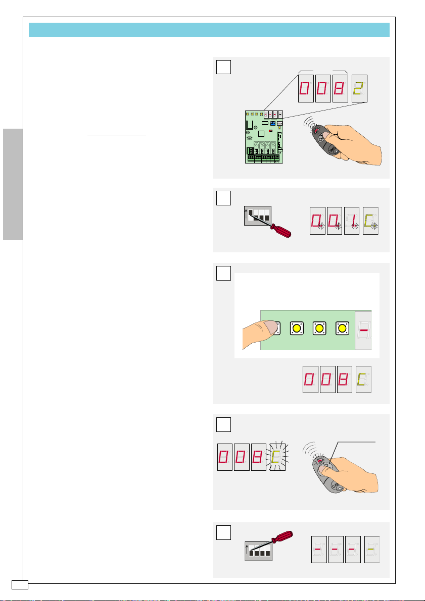
MANU B - Deletes transmitters
IT IS POSSIBLE TO ELIMINATE ONE OR MORE TRANS-
MITTERS FROM THE SYSTEM (TO ELIMINATE THEM
IT IS NECESSARY TO RE-SET THE ENTIRE PRO-
ALL
GRAMMING, SEE MANU D). LOCATIONS EMPTIED
THIS MANNER CAN BE SUBSEQUENTLY OCCUPIED
IN
OTHER TRANSMITTERS (SEE MANU A)
BY
PROCEDURE
A Press any key from the transmitter
to be deleted and read the memory location occupied on viewer A;
B Set dip 1 to ON: the message
+
|C|
appear lighted up without flashing on
ENGLISH
the viewers;
|001|
C with the UP and DOWN keys select
the location of the transmitter to be deleted with the UP and DOWN keys;
D press any key in the TX Master:
flashes on viewer B;
E re-set dip 1 to OFF.
|C|
A
1 3 42
UP
DOWN
AB
ON
1234
OUT TEMP
CLEAR
_
OUT P.C.
TX RX
AC/DC
B
ON
1234
RBE4RC
NC NO C0V12V24V
OUT1 OUT2
OUT3 OUT4
ESEMPIO
C
UP=13/14/15...........499/500/1/2/3.....
DOWN=13/12/11.........3/2/1/500/499/...
-12-
D
TX Master
E
ON
1234
Page 13
UP
1 3 42
DOWN
MANU C - Inhibits a transmitter’s keys
IT IS ALSO POSSIBLE TO INHIBIT ONE OR MORE
TRANSMITTER
INSTEAD OF COMPLETELY ELIMINATING IT.
KEYS (BUT NOT ALL ITS KEYS)
PROCEDURE
A Press a transmitter key to read the
memory location occupied on viewer A;
B set dip 2 to ON (viewer A displays
the first free memory location, viewer B
|S|
displays a flashing
);
C select the transmitter’s location with
|S|
the UP and DOWN keys: the
stops
flashing but remains lighted;
D press the key in the TX Master
corresponding to the key that must be
inhibited in the transmitter: the writing
flashes;
E press (within 10”) the CLEAR key:
the writing stops flashing and remains
lighted;
F re-set dip 2 to OFF.
A
1 3 42
UP
DOWN
AB
ON
1234
OUT TEMP
CLEAR
_
OUT P.C.
TX RX
24V
AC/DC
ON
B
1234
RBE4RC
NC NO C0V12V
OUT1 OUT2
OUT3 OUT4
ESEMPIO
ESEMPIO
C
UP=13/14/15...........499/500/1/2/3.....
DOWN=13/12/11.........3/2/1/500/499/...
ENGLISH
D
P2
TX Master
E
1234
MP
CLEAR
F
ON
1234
-13-
Page 14
CLEAR
1234
UT TEMP
UP
1 3 42
DOWN
3 42
DOWN
MANU D - Deletes the entire programming
Upon COMPLETION OF THIS PROCEDURE, THE
WILL BE COMPLETELY FREE AND THE
MEMORY
INACTIVE.
BOARD
TO RE-SET PROGRAMMING FROM THE MEMORY
ROLL, FIRST RE-MEMORISE THE TX MASTER WITH
PROG A PROCEDURE
THE
PLEASE NOTE! THE TX MASTER MUST BE THE
SAME ONE USED FOR THE PROGRAMMING SAVED
ON THE MEMORY ROLL.
PROCEDURE
A First set dip 1 and then 2 to ON: the
message
ers;
ENGLISH
|001| + |C|
B press the CLEAR key: the
appears on the view-
|c|
flashes on viewer B;
C select the password using the UP
and DOWN keys;
D press the CLEAR key (the entire
|password| + |c|
message flashes) and
then within 5”, press key 3 (the writing
changes to
|C|
with the C flashing);
CLr| + |A|
and then to
|001|
E re-set dips 1 and 2 to OFF.
ON
A
1234
B
C
UP=13/14/15...........499/500/1/2/3.....
DOWN=13/12/11.........3/2/1/500/499/...
ESEMPIO
1,2,3 is the password
+
pre-set by CAME
D
-14-
UT TEMP
12
1
11
10
9
6
5"
E
ON
1234
1234
CLEAR
2
3
4578
Page 15
UP
1 3 42
DOWN
MANU E - Retrieves programming from the Memory Roll
IT IS POSSIBLE TO RETRIEVE THE PROGRAMMING
PREVIOUSLY
TIME
SAVED ON THE MEMORY ROLL AT ANY
(SEE PROG F).
PLEASE NOTE! THE TX MASTER MUST BE THE
SAME ONE USED FOR THE PROGRAMMING SAVED
ON THE MEMORY ROLL.
PROCEDURE
A Insert (*) the Memory Roll in its ap-
propriate connector;
B first press and
keep pressed any
TX Master key and then key 1 on the receiver; Release both only when (10”)
|P|
appears on viewer B;
C remove (*) the Memory Roll and file
it
* WARNING! Prior to any board connect-
ing or disconnecting operation, turn off the
power to the system.
B
PRIMA
A
DOPO
1 3 42
UP
DOWN
MEMORY ROLL
AB
ON
1234
OUT TEMP
CLEAR
RBE4RC
ENGLISH
_
OUT P.C.
TX RX
NC NO C
12V
0V
24V
AC/DC
OUT1 OUT2
OUT3 OUT4
12
1
11
2
All 255 memory blocks transferred to the
receiver scroll in quick succession on
viewer A
C
1 3 42
UP
DOWN
A
AB
ON
1234
OUT TEMP
CLEAR
10
9
3
4578
6
10"
RBE4RC
-15-
Page 16

A
www.came.it
CANCELLI AUTOMATICI
info@came.it
CAME CANCELLI AUTOMATICI S.P.A.
DOSSON DI CASIER (TREVISO)
(+39) 0422 4940 (+39) 0422 4941
SSISTENZA TECNICA
NUMERO VERDE
800 295830
EB
W
E-
MAIL
SISTEMA QUALITÀ
CERTIFICATO
CAME LOMBARDIA S.R.L.___COLOGNO M. (MI)
(+39) 02 26708293 (+39) 02 25490288
CAME SUD S.R.L. _________________NAPOLI
(+39) 081 7524455 (+39) 081 7529109
CAME (AMERICA) L.L.C._________MIAMI (FL)
(+1) 305 5930227 (+1) 305 5939823
CAME AUTOMATISMOS S.A_________MADRID
(+34) 091 5285009 (+34) 091 4685442
CAME BELGIUM____________LESSINES
(+32) 068 333014 (+32) 068 338019
CAME FRANCE S.A.___NANTERRE CEDEX (PARIS)
(+33) 01 46130505 (+33) 01 46130500
CAME GMBH____KORNTAL BEI (STUTTGART)
(+49) 07 11839590 (+49) 07 118395925
CAME GMBH________SEEFELD BEI (BERLIN)
(+49) 03 33988390 (+49) 03 339885508
CAME PL SP.ZO.O_________WARSZAWA
(+48) 022 8365076 (+48) 022 8369920
CAME UNITED KINGDOM LTD___NOTTINGHAM
(+44) 01159 387200 (+44) 01159 382694
 Loading...