

Page 1
CANCELLI AUTOMATICI
| ATOMO SERIES | SÉRIE ATOMO | BAUREIHE ATOMO | SERIE ATOMO
EXTERNAL RECEIVER
MULTIUSER
GER
RBE4MT
Documentazione
Tecnica
T35
rev. 1.1
10/2005
©
CAME
CANCELLI
AUTOMATICI
119RT55-GB
GB
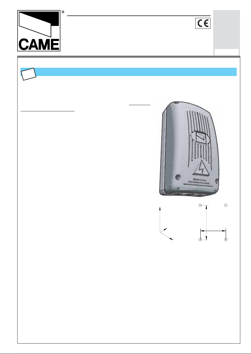
TECHNICAL CHARACTERISTICS
AM 433.92 MHz four-channel receiver to mount outside the automation device’s control
board. It can be matched with CAME series TOP432NA,
TOP434NA, TOP432M, TOP434M, TOP432S, T432,
T434, T438 and TAM432SA transmitters up to a
maximum of 999 units.
ABS outdoor container with IP54 protection level.
With an internal display screen that enables fast
transmitter memorization (max 999) and easy , sporadic
system maintenance (deletion/reset, addition or
change)
It also includes a Memory Roll to make a safety copy of
all the transmitters memorized.
N.B. All programming and system management
operations can also be done via PC with the
relevant software.
The board requires 12 or 24V AC/DC
Output function:
- OUT1 in monostable or bistable mode (see pg. 3)
- OUT2 in monostable mode with 1 to 300-second
adjustable timer (see pg. 3)
224
- OUT3 and 4 in monostable mode
87
104
180
75
N.B. – The receiv er must alwa ys hav e an aerial.
- If there are more than one, do not install receivers at a distance shorter than 4-5 m from each other to
avoid operation irregularities.
- It is preferable to position the aerial at the highest point possible from le vel ground and f ar from buildings.
Page 2
ENGLISCH
11
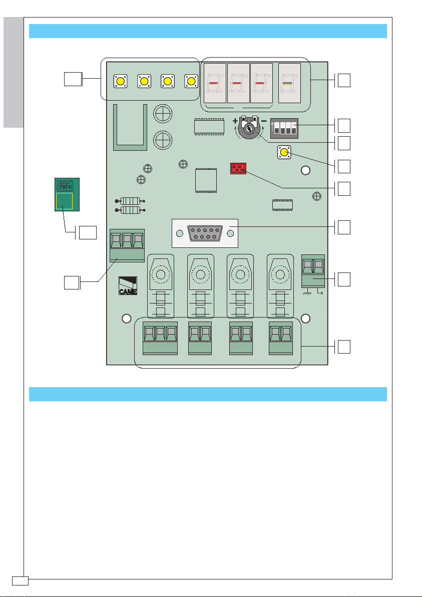
P.C. BOARD RBE4MT
1 2 3 4
UP
DOWN
AB
ON
OUT TEMP
1234
1
2
3
MEMORY ROLL
10
12V
0V
24V
AC/DC
9
RBE4MT
NC NO C
OUT1
OUT2
OUT3 OUT4
MAIN COMPONENTS
MAIN COMPONENTS
1. Program display screen
2. 4-way dip switch
3. OUT2 relay setting trimmer
4. Reset key
5. Memory Roll connector board
6. RS232 connector for PC connection (to use cable RS232
7. Aerial connection terminal board
8. Device control connection terminal boards
9. 12/24V AC/DC power terminal boards
10.Memory Roll board
11. Program keys
CLEAR
4
5
6
7
8
-2-
Page 3
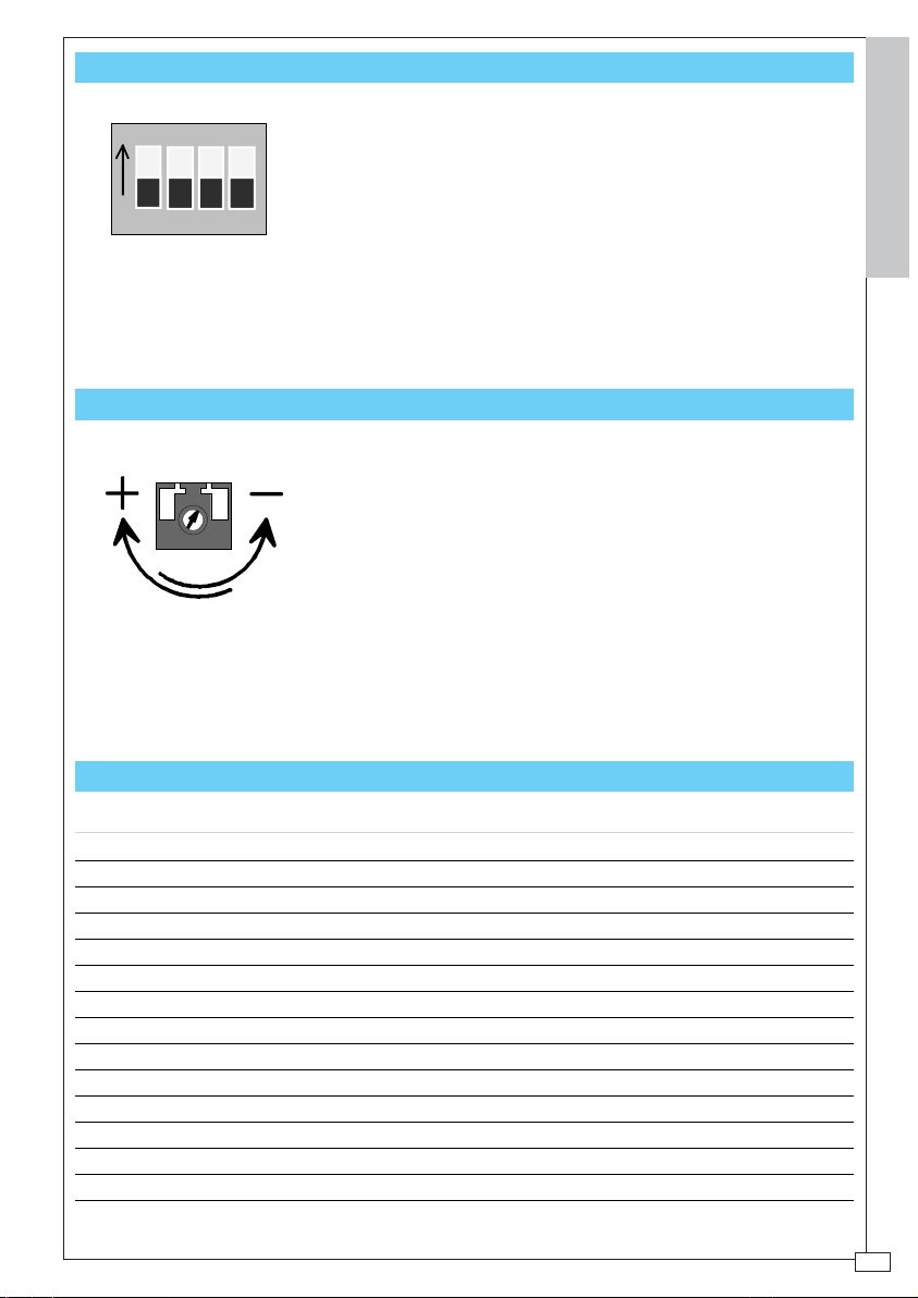
FUNCTION SELECTOR
ON
1234
1 e 2
3 ON Bistable relay in OUT1
3 OFF Monostable relay in OUT1
4 Not used
Programming and Maintenance dip
switch, see pg. 7
TRIMMER PROGRAMMING
MINIMUM activation time setting of
monostable relay in OUT2 output:
1 second
-MAXIMUM activation time setting of
monostable relay in OUT2 output:
300 seconds
ENGLISCH
PROGRAMMING/MAINTENANCE INDEX
- General notes – read carefully
PROG A - Memorize the 1st transmitter (MASTER code )
PROG B - Memorize the next transmitters
Output activation list
PROG C - Prepare a 2nd MASTER code
PROG D - Change the password
PROG E - Save the settings on the Memory Roll board
MANU A - Add transmitters
MANU B - Delete transmitters
MANU C - Delete all the settings
MANU D - Recover the settings from the Memory Roll board
Technical Specifications
pag. 4
pag. 5
pag. 6
pag. 7
pag. 8
pag. 9
pag. 10
pag. 11
pag. 12
pag. 13
pag. 14
pag. 15
-3-
Page 4
GENERAL NOTES
The first transmitter memorized will automatically be recognized by the board as the Master
transmitter (and placed in the first memory position).
The MASTER code will be the system’s main programming and maintenance “agent”. It
should therefore be kept by the person who is in charge of the management of automation
ENGLISCH
devices connected to the receiver.
T o simplify the management of the installation, at the end of the pamphlet we ha ve prepared
a “USER ARCHIVE” with a gr aph in which to enter the name of the user of each transmitter;
please keep this pamphlet together with the MASTER TX
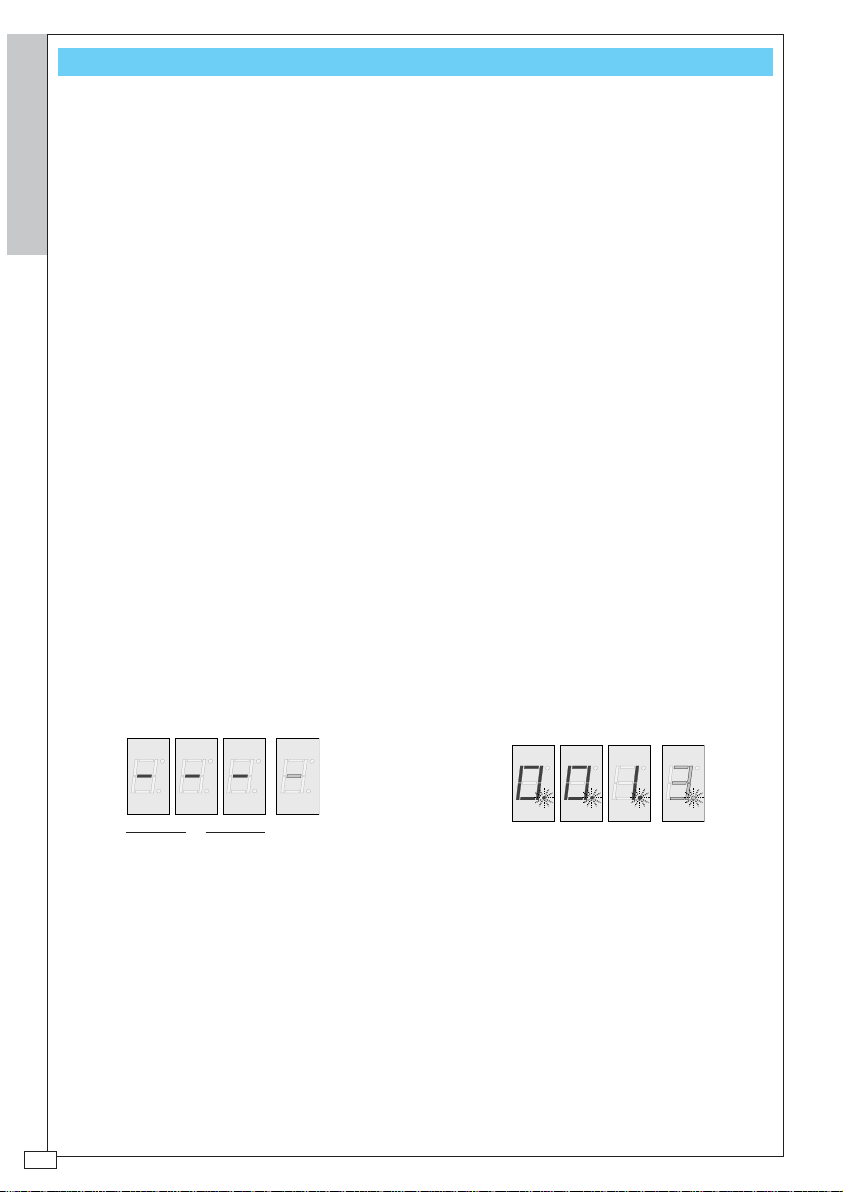
Viewer A displays the numerical position of
the transmitter in the receiver’ s memory (999
memorizable transmitters, including
Viewer B shows how man y OUT outputs are
linked during programming/maintenance
operations.
Masters); a transmitter may be precisely
located from this position.
Flashing dots in the viewers means we are
in MASTER code memory positions (the first
one is always in the 001 position).
BA
Viewers in state of attended with fed
card
During programming/maintenance operations, the visors guide the operator during the
execution of procedures
-4-
Page 5
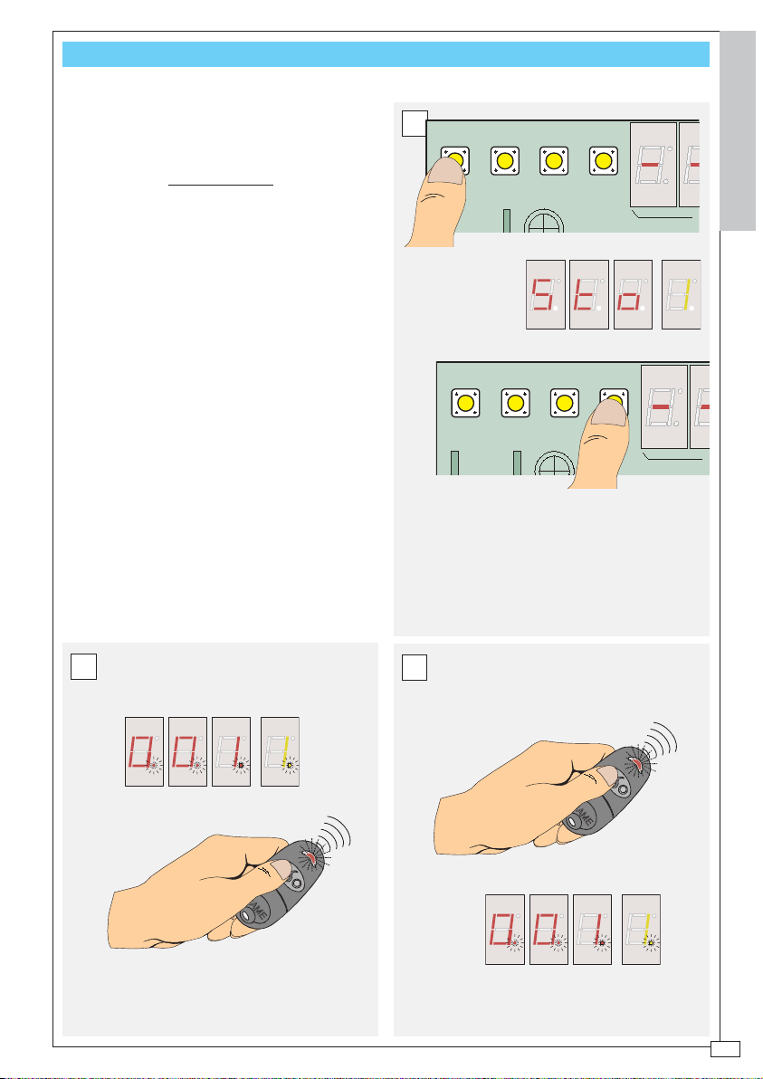
PROG A - MEMORIZATION OF THE FIRST TRANSMITTER (MASTER TX)
UP
1 2 3 4
DOWN
A
UP
1 2 3 4
DOWN
A
FIRST BASIC SYSTEM PROGRAMMING OPERATION. THIS
PROCEDURE
OTHERWISE
ACTIVATES THE BOARD, WHICH IS
INACTIVE.
PROCEDURE
A Press key 1 on the receiver until the
writing |Sto| appears on vie wer A and output
|1| on the viewer; Select the output with ke ys
3-4
B press the MASTER code key until the
/001//1/ appears.
C Check the MASTER code settings by
pressing the same key again. The message
that appears must be as shown below
A
ENGLISCH
C
B
-5-
Page 6

PROG B - TRANSMITTER MEMORIZATION
A
AFTER MEMORIZING THE MASTER CODE, HAVE ALL
TRANSMITTERS AT HAND FOR FAST MEMORIZATION.
THE
THE FOLLOWING PROCEDURE SHOULD ALSO BE USED
OTHER TRANSMITTERS ARE ADDED LATER ON *
IF
ENGLISCH
PROCEDURE
A Press the MASTER code key (10")
until the message
|Sto|
+
|linked output number|
appears on the viewer (after another 5") and
the transmitter’s LED indicator remains lit;
B Select the output or outputs with keys
3-4 (output list on pg. 7).
C Press the corresponding key on the
transmitter to be memorized within 20": the
message on the viewers flashes. Continue
this way for every transmitter to be
memorized for that same output.
D Repeat step B with the corresponding
transmitter key.
A
1 2 3 4
UP
DOWN
AB
ON
1234
10
9
11
10
9
11
12V
24V
AC/DC
RBE4MT
12
1
6
10"
12
1
2
3
4578
6
15"
OUT TEMP
CLEAR
0V
NCNO C
OUT2
OUT1
OUT3 OUT4
2
3
4578
P1
master code
Led
1 2 3 4
B
UP
DOWN
......
......
C
P2
master
coder
D
P2
-6-
Page 7

OUTPUT ACTIVATION LIST
3 4
NC NO C
NO C
OUT2
OUT1
ON
B
ON
B
ON ON
B
ON
B
ON ON
B
ON ON
B
ON ON ON
B
ON
BB
NO C
OUT3 OUT4
NO C
3 4
NC NO C
NO C
OUT2
OUT1
ON ON
B
ON ON
BB
ON ON ON
BB
ON ON
BB
ON ON ON
BB
ON ON ON
BB
ON ON ON ON
BB
NO C
OUT3 OUT4
NO C
THIS TABLE IS FOR VIEWING WHICH OUTPUTS ARE SELECTED ACCORDING TO THE ALPHANUMERICAL VALUE
IN VIEWER B
ENTERED
ENGLISCH
-7-
Page 8

PROG C - PREPARE A SECOND MASTER CODE
SHOULD IT PROVE NECESSARY, IT IS POSSIBLE TO
CONFIGURE
TRANSMITTERS
PROCEDURE
ENGLISCH
ANY OF THE ALREADY MEMORIZED
AS THE SECOND MASTER CODE.
A Press any key on the transmitter to
be configured as second Master and read
the memory position occupied on viewer A;
B set dip switch 2 to ON (viewer A
displays the first available memory position
|P|
while viewer B displays a flashing
);
C use the UP and DOWN ke ys to select
the transmitter’s position as in step A;
D press the MASTER code key (10")
until the writing
|M|,
including the dots, flashes
on viewer B;
E reset dip switch 2 to OFF.
N.B. Only one MASTER code may be
configured in addition to the first one; if the
procedure is repeated with another TX, it
automatically replaces the previous one.
A
1 2 3 4
UP
DOWN
AB
ON
1234
OUT TEMP
CLEAR
12V
0V
24V
AC/DC
RBE4MT
NCNO C
OUT2
OUT1
OUT3 OUT4
ON
B
1234
ESEMPIO
C
UP=13/14/15...........998/999/1/2/3.....
DOWN=13/12/11.........3/2/1/999/998/...
1 2 3 4
UP
DOWN
ESEMPIO
D
1° Master code
12
1
11
2
10
9
3
4578
6
10"
E
ON
1234
-8-
Page 9

CLEAR
1234
OUT TEMP
CLEAR
1234
UT TEMP
UP
1 2 3 4
DOWN
3 4
PROG D - PASSWORD CHANGE
PROCEDURE
A Position dip switches 1 and 2 to ON:
the writing |001| + |C| appears on the
viewers;
B press CLEAR: the writing changes to
|000| + |c| with the “c” flashing;
C use the UP and DOWN ke ys to select
the existing password (in the example the
one preset);
D press CLEAR (the entire |123| + |c|
writing flashes) and after 5", press key 4 (the
writing changes to |000| + |c| with the “c”
flashing);
E enter the new password using the UP
and DOWN keys;
F press CLEAR (the steadily lit letter
|m| appears on viewer B), and reset dip
switches 1 and 2 to OFF.
N.B. The new password may even be
made up of one digit
A
ON
1234
B
C
UP=13/14/15...........998/999/1/2/3.....
DOWN=13/12/11.........3/2/1/999/998/...
1,2,3 is the password
preset by CAME
ENGLISCH
ESEMPIO
D
UT TEMP
E
select a new
password (a number
between 1 and 511)
1234
CLEAR
UP=13/14/15...........998/999/1/2/3.....
DOWN=13/12/11.........3/2/1/999/998/...
1 2 3 4
UP
DOWN
A
F
ON
12
11
10
9
6
1234
1
2
3
4578
5"
-9-
Page 10

UP
1 3 42
DOWN
CLEAR
OUT1 OUT2
OUT3 OUT4
NC NO C
0V
12V
24V
AC/DC
NO C
NO C
NO C
1234
ON
OUT TEMP
AB
MEMORY ROLL
UP
1 2 3 4
DOWN
12
6
3
9
1
2
4578
10
11
10"
PROG E - SAVING DATA ON THE MEMORY ROLL BOARD
ONCE THE INSTALLATION IS COMPLETED, USE THE
MEMORY ROLL BOARD TO SAVE THE SETTINGS MADE
THE RECEIVER.
ON
ENGLISCH
PROCEDURE
A Insert (*) the Memor y Roll board in
the relevant connector;
B first press the MASTER code key
keep it pressed, and then press key 2
and
on the receiver; Release both of them (10")
only when the |U| appears on viewer B;
C remove (*) the Memory Roll board and
file it.
* WARNING! Bef ore connecting or
disconnecting boards, please mak e sure the
power supply is turned is off.
B
BEFORE
A
LATER
C
-10-
All 255 memory blocks transferred over to
the Memory Roll board are displayed on
viewer A in rapid succession.
1 3 42
UP
12V
24V
DOWN
0V
A
AB
ON
1234
OUT TEMP
CLEAR
MEMORY ROLL
Page 11

UP
1 2 3 4
DOWN
MANU A - ADDING TRANSMITTERS
UP
1 2 3 4
DOWN
THERE ARE TWO WA YS TO ADD TRANSMITTERS:
- ADD THEM IN SEQUENCE, THAT IS, MEMORIZE
ON THE FIRST AVAILABLE POSITION* IN THE
THEM
(SEE PROG B)
MEMORY
- OR (THIS PROCEDURE) ADD THEM IN A CHOSEN
AVAILABLE
POSITION.
PROCEDURE
A Position dip switch 2 to ON: the
viewers display the flashing message:
available position|
+
|P|
;
|1st
B use the UP and DOWN keys to
select another available position in which
to add the transmitter;
C Select the output or outputs with
keys 3-4 (output list on pg. 7); the writing
|Sto|
appears;
D Press the MASTER code key and
|Sto|
begins to flash;
E press (within 20") the transmitter’s
new key: after a few seconds the writing
on the viewer will stop flashing and remain
fixed;
F reset dip switch 2 to OFF.
A
ON
1234
B
UP=13/14/15...........998/999/1/2/3.....
DOWN=13/12/11.........3/2/999/998/...
If the P does not flash, it
means that that position is
not available
C
ESEMPIO
ENGLISCH
ESEMPIO
* The first available position could be
the position after the last memorized
transmitter, or an intermediate position
that belonged to a transmitter that has
been eliminated (see MANU B)
D
E
F
ON
1234
12
1
11
2
10
9
3
4578
6
2"
-11-
Page 12

UP
1 2 3 4
DOWN
MANU B - DELETING A TRANSMITTER
ONE OR MORE TRANSMITTERS MAY BE ELIMINATED
THE SYSTEM (TO ELIMINATE ALL OF THEM, ALL
FROM
SETTINGS MUST BE DELETED, SEE MANU D).
THE
POSITIONS CLEARED THIS WAY MAY LATER ON BE USED
ENGLISCH
ANOTHER TRANSMITTER (SEE MANU A)
BY
PROCEDURE
A Press any key of the transmitter to
be eliminated and read the memory position
it occupies on viewer A;
B Position dip switch 1 to ON: the
|001|
+
|C|
steadily lit message
appears;
C use the UP and DOWN ke ys to select
the position of the transmitter to be deleted;
D press any MASTER code key: the
|C|
flashes on viewer B;
E reset dip switch 1 to OFF.
A
1 2 3 4
UP
DOWN
AB
ON
1234
OUT TEMP
CLEAR
12V
0V
24V
AC/DC
RBE4MT
NCNO C
OUT2
OUT1
OUT3 OUT4
ESEMPIO
B
ON
1234
C
UP=13/14/15...........998/999/1/2/3.....
DOWN=13/12/11.........3/2/1/998/999/...
-12-
D
Master code
E
ON
1234
Page 13

CLEAR
1234
UP
1 2 3 4
DOWN
CLEAR
1234
2 3 4
12
6
3
9
1
2
4578
10
11
5"
MANU D - DELETION OF THE ENTIRE PROGRAMMING
WHEN THIS PROCEDURE IS COMPLETED, THE MEMORY
BE EMPTY AND THE BOARD INACTIVE.
WILL
TO RESET THE SETTINGS FROM THE MEMORY ROLL
, FIRST REMEMORIZE THE MASTER TX WITH
BOARD
PROG A PROCEDURE
THE
WARNING! THE MASTER CODE MUST BE THE
SAME ONE WITH WHICH THE SETTINGS WERE SAVED
ON THE MEMORY ROLL BOARD.
PROCEDURE
A First position dip switch 1 and then 2
at ON: the message
|001|
+ |C| appears on the
viewers;
c|
B press CLEAR: the |
flashes on
viewer B;
C select the password with the UP and
DOWN keys;
D press CLEAR (the entire
|c|
message flashes) and press key 3 within
5"(the writing changes from
+ |
C|
with the C flashing);
|CLr|
|password|
+ |A| to
|001|
E reset dip switches 1 and 2 to OFF.
ON
A
1234
B
C
UP=13/14/15...........510/511/1/2/3.....
DOWN=13/12/11.........3/2/1/511/510/...
+
1,2,3 is the password
preset by CAME
D
ENGLISCH
ESEMPIO
E
ON
1234
-13-
Page 14

UP
1 2 3 4
DOWN
12
6
3
9
1
2
4578
10
11
10"
MANU E - DATA RECOVERY FROM THE MEMORY ROLL BOARD
UP
1 3 42
DOWN
CLEAR
OUT1 OUT2
OUT3 OUT4
NC NO C
0V
12V
24V
AC/DC
NO C
NO C
NO C
1234
ON
OUT TEMP
AB
MEMORY ROLL
THE SETTINGS PREVIOUSLY SAVED BY THE MEMORY
ROLL BOARD (SEE PROG F) CAN BE RECOVERED
ANY TIME.
AT
WARNING! THE MASTER CODE MUST BE THE
ENGLISCH
SAME ONE WITH WHICH THE SETTINGS WERE SAVED
ON THE MEMORY ROLL BOARD.
PROCEDURE
A Insert (*) the Memor y Roll board in
the relevant connector;
B first press any MASTER TX key and
keep it pressed, and then press key 1 on
the receiver; Release both of them (10") only
when the |P| appears on viewer B;
C remove (*) and file a wa y the Memory
Roll board.
* WARNING! Before connecting or
disconnecting boards, please make sure the
power supply is turned is off.
B
PRIMA
A
DOPO
C
-14-
All 255 memory blocks transferred over to
the Memory Roll board are displayed on
viewer A in rapid succession
1 3 42
UP
DOWN
A
AB
ON
1234
OUT TEMP
CLEAR
MEMORY ROLL
Page 15

TECHNICAL SPECIFICATIONS
FREQUENCYFREQUENCY
FREQUENCY
FREQUENCYFREQUENCY
INPUT IMPEDENCEINPUT IMPEDENCE
INPUT IMPEDENCE
INPUT IMPEDENCEINPUT IMPEDENCE
1mV SENSITIVITY FOR SUCCESSFUL COMPLETION SIGNAL1mV SENSITIVITY FOR SUCCESSFUL COMPLETION SIGNAL
1mV SENSITIVITY FOR SUCCESSFUL COMPLETION SIGNAL
1mV SENSITIVITY FOR SUCCESSFUL COMPLETION SIGNAL1mV SENSITIVITY FOR SUCCESSFUL COMPLETION SIGNAL
100 ÷ 150 m A100 ÷ 150 m A
100 ÷ 150 m A
100 ÷ 150 m A100 ÷ 150 m A
MODULAMODULA
MODULA
MODULAMODULA
INPUT AINPUT A
INPUT A
INPUT AINPUT A
INPUT WITH AINPUT WITH A
INPUT WITH A
INPUT WITH AINPUT WITH A
N° OF CHANNELSN° OF CHANNELS
N° OF CHANNELS
N° OF CHANNELSN° OF CHANNELS
RELARELA
Y CONTY CONT
RELA
Y CONT
RELARELA
Y CONTY CONT
: 433.92 MHz: 433.92 MHz
: 433.92 MHz
: 433.92 MHz: 433.92 MHz
: 52 Ohm: 52 Ohm
: 52 Ohm
: 52 Ohm: 52 Ohm
VERAVERA
GE RANGE WITH AERIALGE RANGE WITH AERIAL
VERA
GE RANGE WITH AERIAL
VERAVERA
GE RANGE WITH AERIALGE RANGE WITH AERIAL
TIONTION
: OOK: OOK
TION
: OOK
TIONTION
: OOK: OOK
T RESTT REST
: 100 mA: 100 mA
T REST
: 100 mA
T RESTT REST
: 100 mA: 100 mA
CTIVE CHANNELCTIVE CHANNEL
CTIVE CHANNEL
CTIVE CHANNELCTIVE CHANNEL
AA
CTCT
: 10° 250V: 10° 250V
A
CT
: 10° 250V
AA
CTCT
: 10° 250V: 10° 250V
: 4: 4
: 4
: 4: 4
: 175mA: 175mA
: 175mA
: 175mA: 175mA
ENGLISCH
-15-
Page 16

SSISTENZA TECNICA
A
NUMERO VERDE
800 295830
www.came.it
CANCELLI AUTOMATICI
(+39) 0422 4940 (+39) 0422 4941
info@came.it
CAME CANCELLI AUTOMATICI S.P.A.
DOSSON DI CASIER (TREVISO)
E-
SISTEMA QUALITÀ
CERTIFICATO
EB
W
MAIL
CAME LOMBARDIA S.R.L.___COLOGNO M. (MI)
(+39) 02 26708293 (+39) 02 25490288
CAME SUD S.R.L. _________________NAPOLI
(+39) 081 7524455 (+39) 081 7529109
CAME (AMERICA) L.L.C._________MIAMI (FL)
(+1) 305 5930227 (+1) 305 5939823
CAME AUTOMATISMOS S.A_________MADRID
(+34) 091 5285009 (+34) 091 4685442
CAME BELGIUM____________LESSINES
(+32) 068 333014 (+32) 068 338019
CAME FRANCE S.A.___NANTERRE CEDEX (PARIS)
(+33) 01 46130505 (+33) 01 46130500
CAME GMBH____KORNTAL BEI (STUTTGART)
(+49) 07 11839590 (+49) 07 118395925
CAME GMBH ________SEEFELD BEI (BERLIN)
(+49) 03 33988390 (+49) 03 339885508
CAME PL SP.ZO.O_________WARSZAWA
(+48) 022 8365076 (+48) 022 8369920
CAME UNITED KINGDOM LTD___NOTTINGHAM
(+44) 01159 387200 (+44) 01159 382694
 Loading...