

Page 1
PST001
TWISTER SERIES
TRIPOD
TURNSTILE
English
EN
INSTALLATION MANUAL
119G3040EN
Page 2

WARNING!
Important instructions for the safety of people:
READ CAREFULLY!
Foreword
• Use of the products must be restricted to its intended use
(i.e. that for which it was expressly built for). Any other use is
to be considered dangerous. Came Cancelli Automatici S.p.A.
is not liable for any damage resulting from improper, wrongful
or unreasonable use • Keep these warnings with the installation and use manuals issued with the automated system.
Before installing
(preliminary check: in case of a negative
outcome, do not proceed before having
complied with the safety obligations)
• Make sure that the parts you intend to automate are in
good working order, and that they are properly balanced
and aligned. Also, make sure that proper mechanical stops
are already in place • If the operator will be installed at a
height of less than 2.5 m from the ground or other access
level, check whether you will need any protections and/or
warnings • Any gate leaves, fi tted with pedestrian entrances,
onto which you will install an operator, must have a blocking
mechanism when the gate is in motion • Make sure that the
opening of the automated gate is not an entrapment hazard
as regards any surrounding fi xed parts • Do not mount the
operator upside down or onto any elements that may fold
under its weight. If needed, add suitable reinforcements at
the points where it is secured • Do not install onto gates on
either an upward or downward slope (i.e. that are not on fl at,
level ground) • Check that any lawn watering devices will not
wet the gearmotor from the bottom up.
Installation
• Carefully section off the entire site to prevent unauthorised
access, especially by minors and children • Be careful when
handling operators that weigh more than 20 Kg (see installation manual). In such cases, employ proper weight handling
safety equipment • All opening commands (e.g. buttons, key
selectors, magnetic detectors, etc.) must be installed at least
1.85 m from the gate’s area of operation perimeter - or where
they cannot be reached from the outside of the gate. Also,
the direct commands (e.g. push button, or proximity devices,
etc.) must be installed at a height of at least 1.5 m and must
not be accessible to the public • All ‘maintained action’ commands, must be placed where the moving gate leaves, transit
areas and driveways are completely visible • If missing, apply a permanent label that shows the position of the release
mechanism • Before delivering to the client, verify that the
system is EN 12453 (impact test) standard compliant. Make
sure that the operator has been properly adjusted and that the
safety and protection devices, as well as the manual release
are working properly • Where necessary and in plain sight,
apply the Warning Sings (e.g. gate plate).
Special instructions and
advice for users
• Keep the gate’s area of operation clean and clear of any
obstacles. Trim any vegetation that may interfere with the
photocells • Do not allow children to play with the fi xed command devices, or in the gate’s area of operation. Keep any
remote control devices (i.e. transmitters) away from the children as well • Frequently check the system, to see whether
any anomalies or signs of wear and tear appear on the moving
parts, on the component parts, on the securing points, on the
cables and any accessible connections. Keep any joints (i.e.
hinges) lubricated and clean, and do the same where friction may occur (i.e. slide rails) • Perform functional tests on
photocells and sensitive edges, every six months. Keep glass
panels constantly clean (use a slightly water-moistened cloth;
do not use solvents or any other chemical products) • If the
system requires repairs or modifi cations, release the operator
and do not use it until safety conditions have been restored
• Cut off the power supply before releasing the operator for
manual openings. See instructions • Users are FORBIDDEN
to carry out ANY ACTIONS THAT THEY HAVE NOT BEEN
EXPRESSLY ASKED TO DO OR SO INDICATED in the manuals. Any repairs, modifi cations to the settings and extraordinary maintenance MUST BE DONE BY THE TECHNICAL
ASSISTANCE STAFF • On the periodic maintenance log, note
down the checks you have done.
Special instructions and
advice for all
• Avoid working near the hinges or moving mechanical parts
• Stay clear of the gate’s area of operation when in motion •
Do not resist the direction of movement of the gate; this may
present a safety hazard • At all times be extremely careful
about dangerous points that must be indicated by proper
pictograms and/or black and yellow stripes • When using
a selector or command in ‘maintained action’ mode, keep
checking that there are no people in the area of operation of
the moving parts. Do this until you release the command •
The gate may move at any time without warning • Always cut
the power when cleaning performing maintenance.
Page 3

THIS PAGE LEFT INTENTIONALLY BLANK
THIS PAGE LEFT INTENTIONALLY BLANK
Page 4

#
#
Pag.
2
- Manual code:
119G3040
119 G3 04 0 ver.
1.5
1.5 09/2010 © CAME cancelli automatici s.p.a. - The data and information reported in this installation manual are susceptible to change at any time and without obligation on CAME cancelli automatici s.p.a. to notify users.
ENGLISH
4.1 Turnstile
4 Description
2.1 Intended use
1 Legend of symbols
This symbol shows parts to be read carefully.
This symbol shows parts related to safety.
This symbol shows what to tell users.
The TWISTER electromechanical turnstile is designed to select transit flows in high-volume passage areas, and in highly frequented contexts like stadiums, airports, stations, public buildings and in any other places where high-volume flows need to be
regulated and/or selected
Any installation or use other than that shown in this manual is prohibited.
3 Reference Legislation
IMPORTANT SAFETY INSTRUCTIONS FOR INSTALLATION
WARNING: WRONG INSTALLATION MAY CAUSE SERIOUS INJURY, FOLLOW ALL INSTALLATION INSTRUCTIONS
THIS MANUAL IS EXCLUSIVELY MEANT FOR PROFESSIONAL INSTALLERS OR OTHER COMPETENT PERSONS
This product is designed and built by CAME Cancelli Automatici S.p.A. in compliance with the current safety legislation.
It allows passage in the desired direction of one person a time. By activating a command device, the mechanism releases the tripod
which rotates freely allowing people to pass through; the arms automatically return into place and the mechanism locks immediately
after a single passage, waiting for a new command.
The range includes:
001PST001 - Bi-directional electromechanical tripod turnstile AISI 304 steel with scotch-brite fi nishing, complete with ocntrol board,
transponder sensors and high-luminosity LED bi-directional traffi c light with display. Tripod automatic release in case of blackout.
Power: 230 V AC 50 / 60 Hz
Power Draw: 260 mA max
Insulation class: II
Protection rating: IP44
Weight: 60 Kg
The product being described herein complies with the following legislation: see compliance statement.
4.2 Technical Data
2 Intended use and limits
Page 5
11
1
7
5
2
1
6
5
8
9
4
4
8
3
10
12
13
14
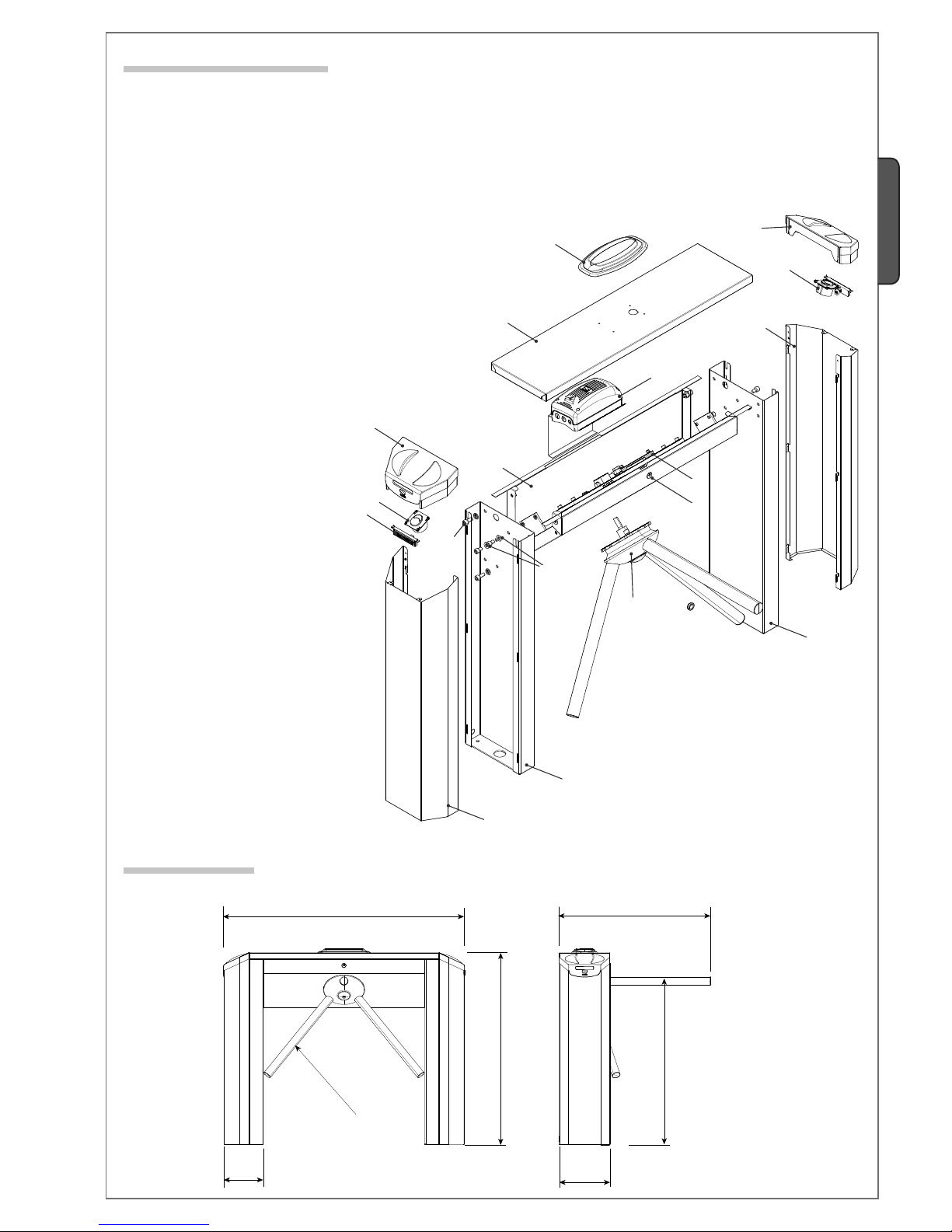
1200
950
750
250
195
ø 40
850
Pag.
3
-
Manual code
:
119G3040
119 G3 04 0 ver.
1.5
1.5 09/2010
© CAME cancelli automatici s.p.a. -
The data and information reported in this installation manual are susceptible to change at any time and without obligation on CAME cancelli automatici s.p.a. to notify users.
ENGLISH
4.4 Dimensions
4.3 Description of parts
Legs1.
Tripod2.
Steel body3.
Casing4.
Casing cover5.
Upper cover6.
Traffic-light with display7.
Transponder8.
Status display9.
Mechanism10.
Control panel11.
Cover lock12.
Screws and washers for fixing the legs13.
Screws for fixing the casing14.
Page 6
EXIT
SWIMMING POOL
Pag.
4
- Manual code:
119G3040
119 G3 04 0 ver.
1.5
1.5 09/2010 © CAME cancelli automatici s.p.a. - The data and information reported in this installation manual are susceptible to change at any time and without obligation on CAME cancelli automatici s.p.a. to notify users.
ENGLISH
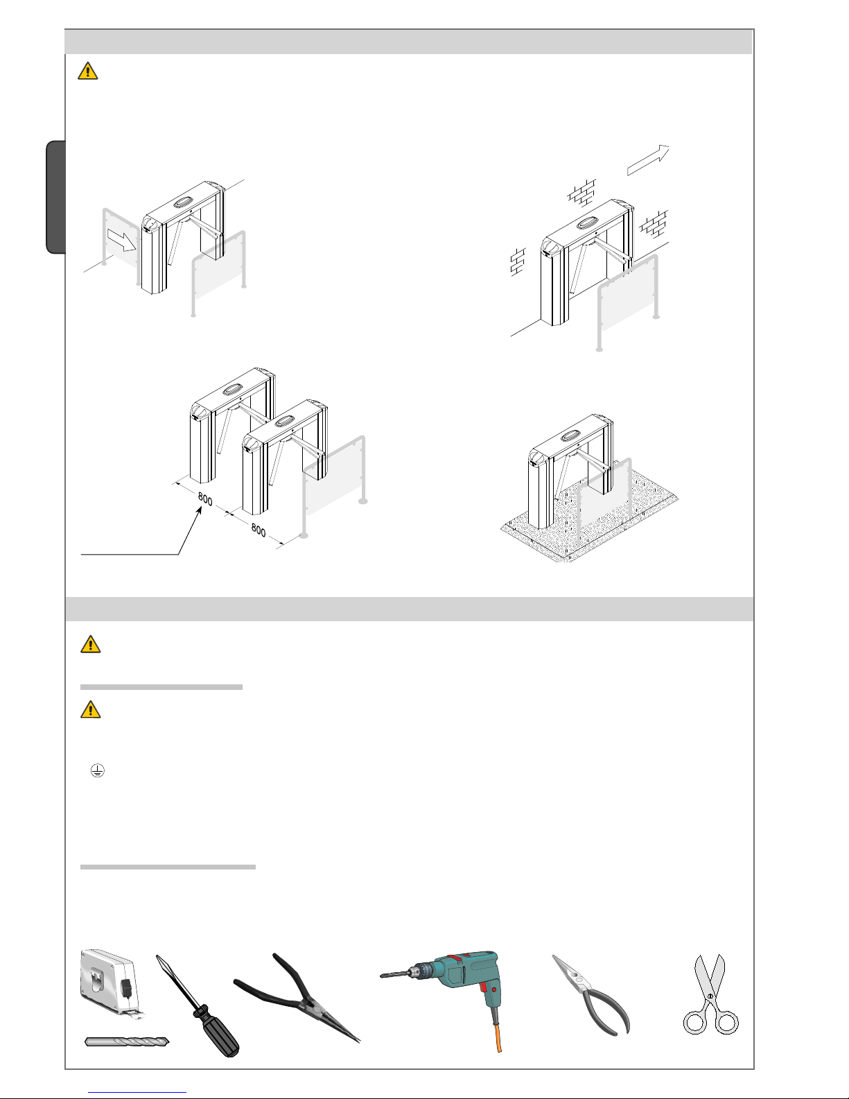
Standard installation Against the wall installation
Multiple installation
Platform installation
5 Application examples
Warning: Turnstile-controlled exits cannot serve as emergency exits. Always have an emergency exit and one also for disabled
persons.
6 Installation
Only skilled, qualified staff must perform the installation, in full compliance of the current legislation.
6.1 Preliminary checks
Before installing the automated device, please:
• Set up a proper omnipolar cut-off device, with contacts more than 3 mm apart, and power source isolation;
• Set up proper tubing and conduits for the electrical cables to go through with enough protection from any mechanical damage;
•
Check that any connections within the container (made to give continuity to the protection circuit) have additional isolation
compared to the other internal power conductors.
Make sure you have all the tools and materials needed to carry out the installation in total safety and in compliance with current
legislation. The figures shows examples of installers’ tools.
6.2 Tools and equipment
Suggested distance
between turnstiles
Page 7
SWIMMING POOL
2
1
3
4
4
5
6
Pag.
5
-
Manual code
:
119G3040
119 G3 04 0 ver.
1.5
1.5 09/2010
© CAME cancelli automatici s.p.a. -
The data and information reported in this installation manual are susceptible to change at any time and without obligation on CAME cancelli automatici s.p.a. to notify users.
ENGLISH
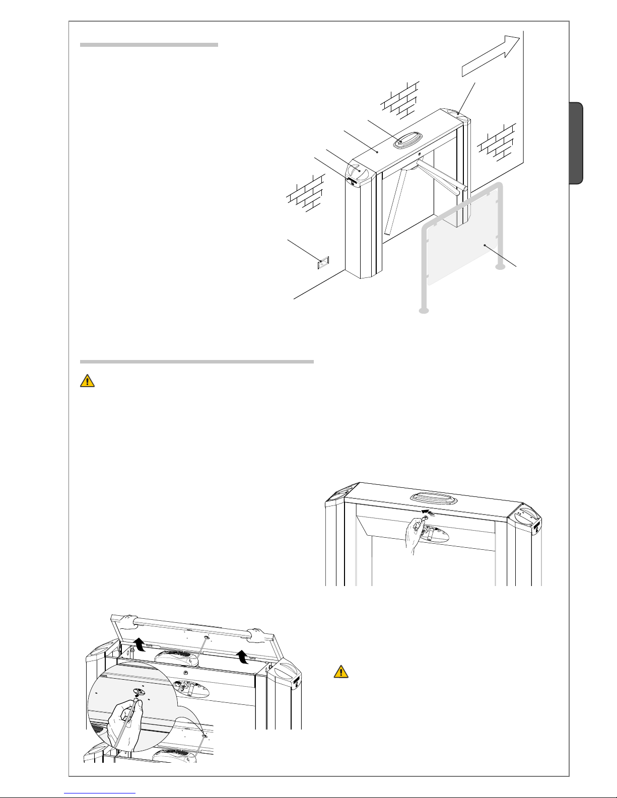
6.3 Standar installation
6.4 Setting up the turnstile
Warning: installation required two people. Use hoisting equipment to move and position the turnstile.
Do not lean on the turnstile until it is solidly anchored, to prevent it from toppling over.
1) Used the issued key to open the lock on the front part of the
turnstile.
Tripod turnstile1.
Traffi c-light with display2.
Electric wiring connector block3.
Transponder for transit access4.
Protection handrail5.
Status displays6.
2)
Raise the cover carefully so as to gently remove the
metal strip from the display (traffic light).
Page 8

1
2
1
2
Pag.
6
- Manual code:
119G3040
119 G3 04 0 ver.
1.5
1.5 09/2010 © CAME cancelli automatici s.p.a. - The data and information reported in this installation manual are susceptible to change at any time and without obligation on CAME cancelli automatici s.p.a. to notify users.
ENGLISH
4) Remove the top cover.
Note: Lift the cover slightly tor easy removal.
5) Remove the two screws that fix the casing to the legs.
6) Remove the protective casings by gently lifting them. Then,
extract the casings.
6) Use the supplied M10 x 60 screws and flat washer to secure
the three arms to the tripod hub.
7) Slide the tripod onto the pin that protrudes out of the body,
secure it using the screw cap and M8 x 20 screw.
Page 9

200
870
ø11
ø40
10
0
Ø12 mm
Ø12 mm
Pag.
7
-
Manual code
:
119G3040
119 G3 04 0 ver.
1.5
1.5 09/2010
© CAME cancelli automatici s.p.a. -
The data and information reported in this installation manual are susceptible to change at any time and without obligation on CAME cancelli automatici s.p.a. to notify users.
ENGLISH
5) Insert the nogs into the holes.
6) Place the turnstile over the nogs and pass the cable duct
through the central hole.
Screw the turnstile to the ground using the ratchet spanner.
6.5 Preparing the site and fixing the turnstile to the ground.
1) Check that the floor where the turnstile is anchored is level
and without warping.
3) Drill the marked holes.
2) Depending on the size of the passage, decide where to
install the turnstile and any accessories that should be added,
marking the fixing holes with a pencil respecting the measurements given in the drawing.
4) Set up corrugated tubes for cables to go through.
If the ground cannot be drilled use a platform (001PSPEBUL) for
fixing the turnstile and accessories.
Page 10

L
N
+ E
-
EbA EbA EbI EbI
10
S2
S12EM432111
Pag.
8
- Manual code:
119G3040
119 G3 04 0 ver.
1.5
1.5 09/2010 © CAME cancelli automatici s.p.a. - The data and information reported in this installation manual are susceptible to change at any time and without obligation on CAME cancelli automatici s.p.a. to notify users.
ENGLISH
7 Electric cabling
Use the proper cable clamps to secure
the cables inside the box in the control
panel.
Threading the power supply (and that
of any accessories) cable through the
bottom plate of the turnstile leg.
Pass the cable through the hole in the
top of the turnstile leg.
Threading the power supply cable (alternatively to the hole on the base plate)
through a cable gland at the bottom of
the turnstile leg.
Earth
Cable clamps
Hole
Hole
7.1 Cable types and sections
N.B. If the cable length differs to that shown in the table, determine cable section based on the actual power draw by the connected
devices and according to what is prescribed by law CEI EN 60304-1.
For sequential connections on the same line, length-measurements by the table must be converted on the basis of draw and actual
distances. To connect any products not mentioned in this manual, see documentation provided with said products.
Cable clamps
Connections Cable types
Cable length
1 < 10 m
Cable length
10 < 20 m
Cable length
20 < 30 m
Power to electrical panel 230 V
FROR CEI 20-22
CEI EN
50267-2-1
3G x 1,5 mm
2
3G x 1,5 mm
2
3G x 1,5 mm
2
Power to accessories 2 x 0,5 mm
2
2 x 0,5 mm
2
2 x 1 mm
2
Command and safety devices 2 x 0,5 mm
2
2 x 0,5 mm
2
2 x 0,5 mm
2
Page 11

L
N
+ -
+ E
-
A B
GND
EbA EbA EbI EbI
10
S2
S12EM432111
6
7
8
9
15
14
3
2
2
4
5
11
10
12
13
1
16
Pag.
9
-
Manual code
:
119G3040
119 G3 04 0 ver.
1.5
1.5 09/2010
© CAME cancelli automatici s.p.a. -
The data and information reported in this installation manual are susceptible to change at any time and without obligation on CAME cancelli automatici s.p.a. to notify users.
ENGLISH
FUSE TABLE
To protect: Fuse rating:
Control board (line) 1,6A-F
Accessoriesi 1,6A-F
8.2 Main Components
Transf ormer1.
Transformer connection terminals2.
1.6A accessories Fuse3.
Endpoint connection terminal4.
1.6A line fu se5.
230 V AC control board power terminals6.
Terminals for connecting accessories and com-7.
mand systems.
electro-block connection terminal board8.
Not used terminal board 9.
Transponder connection terminals10.
R700 board connectors11.
Memory roll board connectors12.
Traffic-light display connection terminal13.
Functions programming buttons14.
RBM84 connection terminal15.
Signal LED16.
The control panel is powered by 230 V AC on terminals L-N, with
max frequency of 50/60Hz
The 24 V power supply is of the SELV type.
The command and control devices and accessories are 24 V D.C.
Warning! The accessories must not comprehensively exceed
35W.
All connections are quick-fuse protected, see table.
The functions and user interface are set and displayed on the
software-managed display.
8.1 General description
8 Control panel
The defi nable command and control functionalities are:
- clock-wise activation;
- counter clock-wise activation;
- Stop command;
- emergency command.
WARNING: before doing any work inside the equipment, cut the
power mains.
Page 12

10 11 1 2 3 4 EM 2 S1 S2
A
B
GND
A
B
GND
L
N
Pag.
10
10 - Manual code:
119G3040
119 G3 04 0 ver.
1.5
1.5 09/2010 © CAME cancelli automatici s.p.a. - The data and information reported in this installation manual are susceptible to change at any time and without obligation on CAME cancelli automatici s.p.a. to notify users.
ENGLISH
Counter-clockwise activating button / (N.O. contact)
Release the tripod in an anti-clockwise direction. If
no other command is given, the turnstile relocks itself
automatically after the time set in the “F5” function.
Clockwise activating button / (N.O. contact)
Release the tripod in a clockwise direction. If no
other command is given, the turnstile relocks it self
automatically after the time set in the “F5” function.
RBM84 - Access control
Software for recording user movements and for managing
personalised permits according to the program given to
each single user.
9 Electrical connections
230 V AC power, 50/60Hz
frequency
Connect the earth to the terminal fi tted on the turnstile.
9.1 Power
9.2 Optional devices
Panic button / (N.C. contact)
Activating the contact triggers total block of the
turnstile. Note: Short circuit if unused!
Emergency button / (N.C. contact)
Pressing the button allows the tripod to turn in both
directions.
Note: Short circuit if unused!
Terminals for powering 24 V AC accessories,
max 250 mA and 35 W
Page 13

+
E
-
L1T
L2T
24V
0V
EbA EbA
EbI EbI
L
N
+ -
+ E
-
A B
GND
EbA EbA EbI EbI
10
S2
S1 2 EM 4 3 2 1 11
Pag.
11
11 -
Manual code
:
119G3040
119 G3 04 0 ver.
1.5
1.5 09/2010
© CAME cancelli automatici s.p.a. -
The data and information reported in this installation manual are susceptible to change at any time and without obligation on CAME cancelli automatici s.p.a. to notify users.
ENGLISH
Endpoint
Clockwise activated trasponder / (N.O. contact)
Release the tripod in a clockwise direction. If no other command is given, the turnstile relocks itself automatically after
the time set in the “F5” function.
Counter- clockwise activated trasponder / (N.O. contact)
Release the tripod in an anti-clockwise direction. If no other
command is given, the turnstile relocks itself automatically
after the time set in the “F5” function.
Blue
White
Pink
Red
Electromagnet
Red
Red
Red
Red
S1 - Red
GND - Black
Status displays
TSP00
White
Brown
Green
Transformer
9.3 Already connected devices
Traffi c-light with display
Page 14
#!.#%,,)!54/-!4)#)
#!.#%,,)!54/-!4)#)
1
2
1
2
Pag.
12
12 - Manual code:
119G3040
119 G3 04 0 ver.
1.5
1.5 09/2010 © CAME cancelli automatici s.p.a. - The data and information reported in this installation manual are susceptible to change at any time and without obligation on CAME cancelli automatici s.p.a. to notify users.
ENGLISH
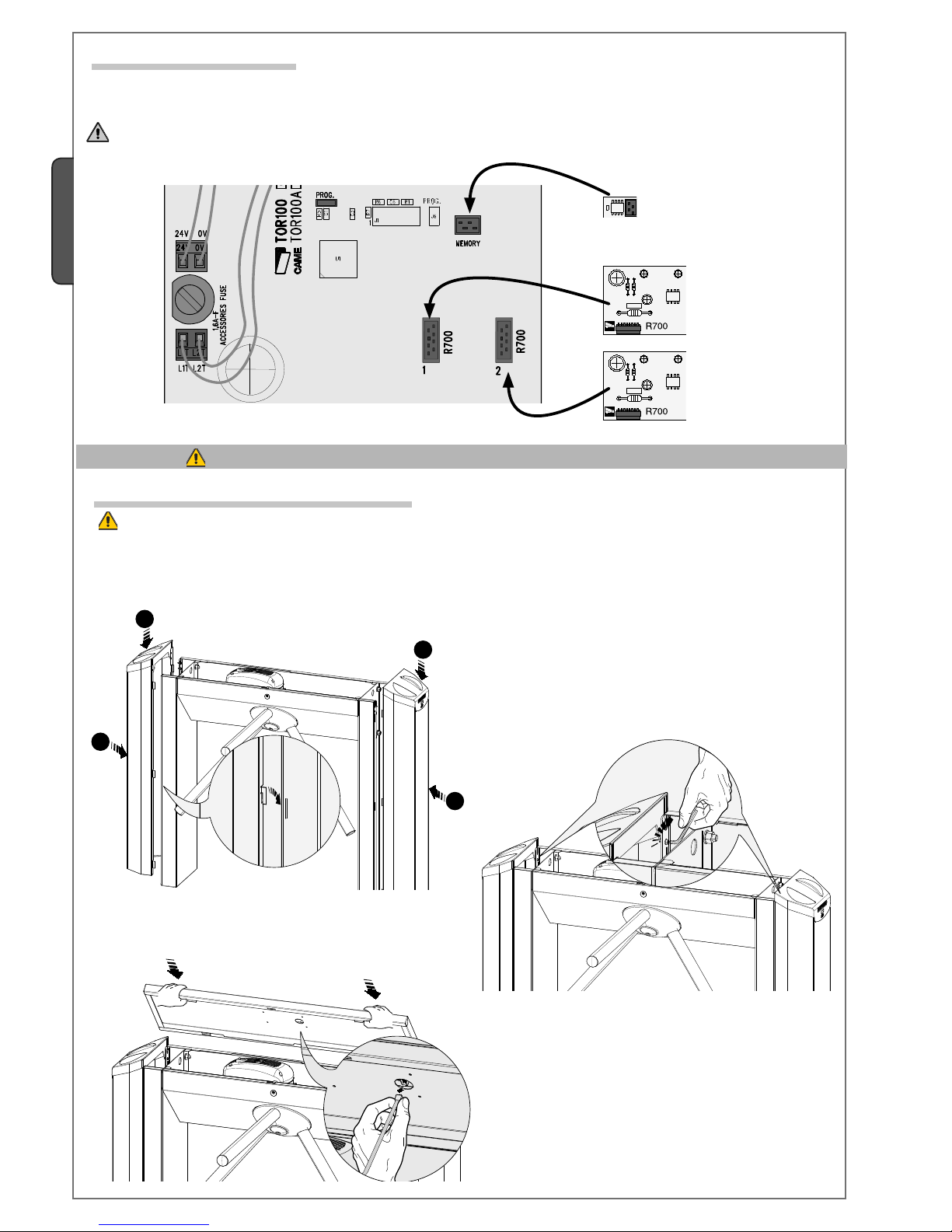
Decoder boards for
transponders
LThe R700 boardscommand the turnstile with (TZP00/LT001) proximity sensors and the memory roll to save and load any settings
including registered users on another board
The R700 and Memory Roll boards must be inserted when the power is disconnected.
9.5 Decoder boards
Once the power is connected, wait 10 seconds before proceeding with any operations
Memory roll
9.6 Fixing the side casings and cover
1) Remount the side casing following the procedure given at point
6 on page 5 in reverse order.
2) Introduce the casings and screw them in place.
3) Introduce the top cover and connect the strap to the traffic
light.
IMPORTANT: before proceding with programming, make sure the electric cables are out of the way of the mechanical
parts.
Page 15

{
{
{
{
{
< 00:00 >
F - 1
F - 2
F - 3
F - 4
F - 5
F - 6
F - 7
F - 8
F - 17
F - 16
F - 15
F - 14
F - 13
F - 12
F - 11
F - 10
F - 9
TSP2
TSP1
12 :30
Pag.
13
13 -
Manual code
:
119G3040
119 G3 04 0 ver.
1.5
1.5 09/2010
© CAME cancelli automatici s.p.a. -
The data and information reported in this installation manual are susceptible to change at any time and without obligation on CAME cancelli automatici s.p.a. to notify users.
ENGLISH
The ENTER button is for:
-entering the menu
-confirming or memorising the set value
The ESC button is for:
-exiting the menu
-cancelling the settings
Transponder to insert, modify and confirm functions via the Master card
without having to open the turnstile.
Position the Master card near the transponder receiver and carry out the
settings required which will be displayed step-by-step on the display.
10 Programming
10.1 Description of commands
The <> buttons are for:
- moving among menu items;
- increasing or decreasing a setting
Display to view the functions and settings that are assigned
via programming buttons or transponder
10.2 Menu structure
Creating the MASTER card
Creating a new card
Cancelling a card
Cancelling all of the cards
Inserting timeout time
Chosing the information-type on display
Cancelling the number of passages
Setting the number of passages
Setting the time and date
Data reading in the memory roll
Data recording in the memory roll
Differential entrance management
Antipassback mode (On or Off)
Setting the entrance direction
Periferal device number
Standalone or online mode
Enabling the Intrusion Buzzer
N.B. Functions F-2, F-3 and F-4 appear on the display only when the MASTER pass is generated.
Transponder used to
confirm the functions
and settings (ENTER)
Transponder used to
change, increase and
decrease a value (< >)
The functions can be programmed from the internal keypad on the control panel or from the Master pass.
Warning: to use the programming function, both display and transponder commands must be installed on the turnstile.
Also, all NC contacts, if unused, must be shortcircuited.
Page 16

F - 1
F
-
2
---
F
-
1
F
-
2
F - 3
F
-
4
500
CLR-A
F - 4
F
-
5
F - 5
F
-
6
OFF
65000
F - 6
F
-
7
10:00
F - 3
1
3
2
500
1
3
2
500
CLR
10
12
11
60
F
-
2
F
-
3
F
-
4
F
-
5
Pag.
14
14 - Manual code:
119G3040
119 G3 04 0 ver.
1.5
1.5 09/2010 © CAME cancelli automatici s.p.a. - The data and information reported in this installation manual are susceptible to change at any time and without obligation on CAME cancelli automatici s.p.a. to notify users.
ENGLISH
10.3 Functions menu
Function 1: Creating the MASTER card
Creating the MASTER, activates the programming functions without opening the small-door.
See detailed function on pages 14 and 15.o.
Function 2: Creating a new card
Creating new cards (max. 500 cards)
See detailed fucntions on page 16.
Function 3: Cancelling a card.
Select the number of the pass that has to be cancelled using the keys or place the pass on the transponder (TSP1), the display
will show the pass number. Press ENTER to confirm cancellation.
Function 4: Cancelling all cards.
Cancelling all the cards memorised in the software.
Function 5: Setting the timeout time.
To set the time that the turnstile stays released after a button or transponder command (2-3 / 2-4).
The waiting time can be set between 10” and 60”.
Function 6: Chosing the type of information on the display.
Chosing the type of information to view on the display between the number of passages, the time or neither
Max 500 users
Page 17

F - 10
F
-
11
65000
F - 7
F
-
8
CLR
OFF
F - 8
F
-
9
02
01
65000
12:00
2008
OFF
02
01
60
F - 11
F
-
12
OFF
ON
F - 12
F
-
13
1
3
2
60
:00 12:
31
07
12
Sto
ON
F - 9
F
-
10
F
-
9
F -
6
F
-
7
F
-
10
F
-
11
F
-
8
Pag.
15
15 -
Manual code
:
119G3040
119 G3 04 0 ver.
1.5
1.5 09/2010
© CAME cancelli automatici s.p.a. -
The data and information reported in this installation manual are susceptible to change at any time and without obligation on CAME cancelli automatici s.p.a. to notify users.
ENGLISH
Function: Cancelling the number of passages
Cancelling the number of passages (entrance-exit) made by the turnstile
Function 8: Setting the maximum number of passages.
Setting the number of maximum passages allowed in the direction established by the “F-13” function.
From 1 to 65,000 passages or leave unlimited passages “OFF”.
Note: the number appearing on the display shows user presence at the entrance at that moment.
Function 9: setting the time and date.
Note: press the ENTER button until the datum you wish to change appears then press the <> buttons to increase or decrease the
datum, press ENTER until the automatic setting choice for daylight savings time (ON) or only set the GMT (OFF) time for the entire
year, confirm by pressing ENTER again.
Function 10: intrusion alarm Buzzer
Activating the buzzer in case of intrusion of deactivation. The activation time can be set between 1” and 60”.
Function 11: StandAlone or Online mode.
Stand-Alone (the turnstile works automatically – OFF) or On-Line (the turnstile is connected to and managed by the RBM84
access control system – ON).
Function 12: Periferal device number.
Assign to each turnstile (if more than one) a peripheral number (e.g. access control, etc.)
minutes
Hour
Days of the week, e.g.: 1 =
Monday, 2 = Tuesday, etc.
Day of the monthMonthyear
Page 18

< ---
--- >
F - 14
F
-
115
F - 13
F
-
14
< OFF >
< ON >
000
F
-
16
F - 17
000
OFF
< -2- >
< -6- >
< -5- >
< -4- >
< -3- >
F - 15
F
-
16
< -1- >
F
-
13
F
-
12
F
-
14
F - 17
F - 16
F
-
15
Pag.
16
16 - Manual co de:
119G3040
119 G3 04 0 ver.
1.5
1.5 09/2010 © CAME cancelli automatici s.p.a. - The data and information reported in this installation manual are susceptible to change at any time and without obligation on CAME cancelli automatici s.p.a. to notify users.
ENGLISH
Function 13: Setting the direction for the passage counter.
Assign to the turnstile the direction for which the counter records the entrances set by function “F-8”. The flashing arrow indicated
the direction.
Function 14: Antipassback mode.
Activate or deactivate the Antipassback functions.
Prevents entering an area when the person is already inside. It can be used to prevent using the same pass for two or more consecutive accesses to the same area: for example in a gym, to prevent clients entering with the personal pass of a client who is already
inside.
Funzione 16: Data recording in the memory roll.
It saves registered users and data settings in the memory roll.
Funzione 17: Data reading in the memory roll.
It loads registered users and data settings in the memory roll.
Intermittent arrow
Function 15: Differentiated passage mamangement.
Free = free passage for all users (Green Arrow).
Blocked = passage not allowed to all users (Red Arrow)
Controlled = passage allowed only to cleared users (Green Intermittent Arrow).
OFF = passaggio consentito solo a utenti abilitati su entrambe le direzioni (Freccie ros-
se).
Attention: when one of these 6 functions is activated, the antipassback function (Function 14)
and the maximum number of transits (Function 8) are deactivated.
12 :30
OFF Controlled Controlled
-1- Fr ee Bl ocked
-2- Blocked Free
-3- Controlled Blocked
-4- Blocked Controlled
-5- Controlled Free
-6- Free Controlled
Page 19

12 :30.
X2
F - 1
F - 1
F - 2
OFF
F - 8
01
02
Sto
Clr
Pag.
17
17 -
Manual code
:
119G3040
119 G3 04 0 ver.
1.5
1.5 09/2010
© CAME cancelli automatici s.p.a. -
The data and information reported in this installation manual are susceptible to change at any time and without obligation on CAME cancelli automatici s.p.a. to notify users.
ENGLISH
10.5 Creating a master card
1) Press ENTER twice consecutively.
IMPORTANT: before actually creating the card, carefully read the instructions.
Follow the order of the following instructions otherwise the programming will not work.
To enter the functions menu, press
the ENTER button.
To choose the function, press
the arrows…
…then press ENTER
…then press ENTER to
confirm…
also for the the “submenus”, move by using the
arrows … to raise or lower
a value.
Open the turnstile’s upper cover
and position it turned by 90° above the body, so that the display
can be easily read. Open the
electrical oanel box to use the
programming buttons.
10.4 Browsing and programming the menu via the internal button console.
IMPORTANT: before doing any programming, carefully read the instructions.
Follow the order of the following instructions otherwise the programming will not work
…to modify increments, settings, creating cards, after confirming with ENTER, “Sto” appears on the display.
…to cancel cards, number of passages, after confirming
with ENTER, “Clr” appears on the dislay.
Note: the flashing dot on the display shows that the Master
pass has not been generated yet.
Page 20

----
Sto
F - 1
F - 1
F - 2
TSP1
TSP2
TSP1
TSP2
TSP1
TSP2
TSP1
TSP2
Pag.
18
18 - Manual code:
119G3040
119 G3 04 0 ver.
1.5
1.5 09/2010 © CAME cancelli automatici s.p.a. - The data and information reported in this installation manual are susceptible to change at any time and without obligation on CAME cancelli automatici s.p.a. to notify users.
ENGLISH
2) the “S1” LED transponder flashes RED and the lines will appear on the display.
3) Within 10 seconds, approach a the chosen MASTER card to the flashing transponder and leave it for several seconds until the
display shows the “Sto” (Storage) letters.
Intermittent Red LED
10.6 Browsing and programming the menu using the Master card.
1) To enter the function menu, place the Master pass on the transponder (TSP1). The display will show “F1”.
The transponder remains green throughout the programming time. Carrying out this operation is like keeping the “ENTER” button
pressed.
2)By moving the Master card, alternatively either right or left, or vice-versa, allows you to set the various functions without opening the turnstile.
Sensor used to confirm functions and
settings (ENTER)
Warning: always first create the MASTER card and keep it to be able to browse the functions menu.
Note: if the MASTER card is misplaced, follow the same procedure from point 1 using a new card.
red LED
red LED
green LED
Transponder (TSP2) used to change, increase or
decrease a value (endless loop system).
Intermittent Red LED
Page 21

F - 2
F - 2
F - 1
F - 2
F - 1
TSP1
TSP2
TSP1
TSP2
Pag.
19
19 -
Manual code
:
119G3040
119 G3 04 0 ver.
1.5
1.5 09/2010
© CAME cancelli automatici s.p.a. -
The data and information reported in this installation manual are susceptible to change at any time and without obligation on CAME cancelli automatici s.p.a. to notify users.
ENGLISH
3) Replace the Master pass on the transponder (TSP1) to enter the F-2 function.
4) The transponder (TSP2) led will start flashing red.
10.7 Creating a new card using the Master.
2) Place the Master pass on the transponder (TSP2). The display will scroll the functions; continue scrolling up to function F2.
IMPORTANT: before doing any programming, carefully read the instructions.
Follow the order of the following instructions otherwise the programming will not work
Master
1) Place the Master pass on the transponder (TSP1). The display will show “F-1”
Green Led
Green Led
Master
Master
Green Led
Intermittent Red LED
Page 22

Sto
TSP2
Pag.
20
20 - Manual code:
119G3040
119 G3 04 0 ver.
1.5
1.5 09/2010 © CAME cancelli automatici s.p.a. - The data and information reported in this installation manual are susceptible to change at any time and without obligation on CAME cancelli automatici s.p.a. to notify users.
ENGLISH
5) Within 10” rest the card or cards you wish to memorise, one at the time on the flashing transponder. When “Sto” appears on
the display this is confirmation of memorisation of the new cards.
Card 1
Card 2
Card n
10.8 Error messages and warnings
“Err-A” – Access denied because the “user is already inside”.
“Full” – Access denied because the maximum number of transits has been reached.
“Err” – During pass storage (function 2) it shows that an attempt is being made to memorise a pass that is already stored.
Intermittent Red LED
11 Safety instruction
12 Maintenance
Impact danger
Danger voltage running
through parts
Transit prohibited during operation.
Important general safety instructions. This product must be only used for its specific intended
purpose. Any other use is wrongful and therefore dangerous. The manufacturer is not liable for any
harm or damage caused by improper, wrongful or unreasonable use.
Do not allow children to play or loiter in the operating range of the turnstile.
Keep command and control devices out of reach of children, to prevent the turnstile from being
accidentally activated.
Immediately suspend use of the turnstile if any anomalies are manifested.
Carry out the following periodic maintenance:
Check turnstile’s internal cabling, check that cables are not disconnected or damaged.
By turning the tripod, check for any faulty movements and that the rotation is homogenous. A sudden blocking may indicate a
malfunction.
By trying to move it, try to properly secure the turnstile to the ground, because unstable securing can result in danger.
Do not clean the turnstile with products containing chemical agents that could damage the stainless steel or plastic
parts, do not use abrasive products or cloths which could scratch the surface.
12.1 Periodic maintenance
Before carrying out any maintenance work, turn the power off to prevent any possible risks involved with the device moving
accidentally.
Warning: opening the turnstile only 60° will cause the tripod to automatically return.
Warning: if leaning onto one of the tripod’s arms before it is released, the lock function will not work and the turnstile
stays closed.
Page 23

Pag.
21
21 -
Manual code
:
119G3040
119 G3 04 0 ver.
1.5
1.5 09/2010
© CAME cancelli automatici s.p.a. -
The data and information reported in this installation manual are susceptible to change at any time and without obligation on CAME cancelli automatici s.p.a. to notify users.
ENGLISH
12.2 Trouble shooting
DISFUNCTIONS POSSIBILI CAUSE CHECKS AND REMEDIES
The turnstile stays released in both directions
of travel
• No power
• Emergency button is pressed
• Electroblocks are not working.
• Check power source
• Reload the emergency button
• Call assistance
The turnstile only releases in one direction
• One of the electroblock is broken down
• The spring of one of the electroblocks has become
disconnected
• 2-3 or 2-4 button is pressed
• Call assistance
• Call assistance
• Call assistance
The turnstile stays
blocked
• The person passing through leaned on the arm
before the release took place.
• Both electroblocks stay wound up
• Stop button activated
• Tell the person not to lean on the arm and
try to release
• Call assistance
• Check the release command works correctly
The turnstile blocks
suddenly
• The hydraulic brake is not working properly • Call assistance
Came Cancelli Automatici company is ISO 9001:2000 certified for its in-house quality system and ISO 14001 certified in terms of its environmental practices.We kindly ask you to keep on respecting the environment – CAME considers this one of the fundamentals of its own development and market operation strategies, by simply following these brief disposal instructions:
DISPOSING OF THE PACKAGING
The packaging components (cardboard, plastic, etc.) are considered solid urban waste and may disposed without any trouble in the proper cycling
bins supplied by your municipality.
DO NOT DISPOSE OF IN THE ENVIRONMENT
DISPOSING OF THE PRODUCT
Our products are made with different materials. The majority of these (i.e. aluminium, plastic, iron, electrical cables) consist of solid urban waste.
They can be recycled at authorised recycling centres. Other components (electronic boards, remote control batteries, etc.) may contain toxic substances.
They must therefore be removed and turned into authorised firms that will dispose of them properly. Before proceeding it is always best to check
the specific legislation in your municipality.
DO NOT DISPOSE OF IN THE ENVIRONMENT!
13 De-commissioning and disposal
14 Declaration
MANUFACTURER’S STATEMENT
Pur
suant to Lo
w Vol
tage
Dir
ective 2006/95/C
E
CAME Cancelli Automatici S.p.A.
via Martiri della Libertà, 15
31030 Dosson di Casier - Treviso - ITALY
tel (+39) 0422 4940 - fax (+39) 0422 4941
internet: www.came.it - e-mail: info@came.it
hereby declares that these pedestrian tra c-fl ow control operators, called
PST001
are conform to the essential requirements and dispositions established by the Directives
and applicable sections of reference Standards, as listed below:
-- DIRECTIVES -- -- STANDARDS --
2006/95/CE L
OW VOLTAGE DIRECTIVE EN 13241-1
EN 61000-6-2
EN 61000-6-3
EN 60335-1
EN 60335-2-103
2004/108/CE E
LECTROMAGNETIC
C
OMPATABILITY DIRECTIVE
MANAGING DIRECTOR
Mr. Gianni Michielan
Reference code to request a true copy of the original: DDC L EN O001 - 4.0
Page 24

CAME
CAME
France
France
S.a .
S.a. FRANCE
7, Rue Des Haras
Z.i. Des Hautes Patures
92737
Nanterre C ed ex
Nanterre Cedex
(+33) 1 46 13 05 05
(+33) 1 46 13 05 00
GERMANY
CAME Gmb h Se efeld
CAME Gmbh Seefeld
Akazienstrasse, 9
16356
Seefeld
Seefeld Bei Berlin
(+49) 33 3988390
(+49) 33 39883985
CAME Au to matismes S.a.
CAME Automatismes S.a. FRANCE
3, Rue Odette Jasse
13015
Marseill e
Marseille
(+33) 4 95 06 33 70
(+33) 4 91 60 69 05
U.A.E.
CAME Gul f Fz e
CAME Gulf Fze
Offi ce No: S10122a2o210
P.O. Box 262853
Jebel Ali Free Zone -
Dubai
Dubai
(+971) 4 8860046
(+971) 4 8860048
CAME Au to matismos S.a.
CAME Automatismos S.a. SPAIN
C/juan De Mariana, N. 17-local
28045
Madrid
Madrid
(+34) 91 52 85 009
(+34) 91 46 85 442
RUSSIA
CAME Rus
CAME Rus
Umc Rus Ll c
Umc Rus Llc
Ul. Otradnaya D. 2b, Str. 2, offi ce 219
127273,
Moscow
Moscow
(+7) 495 739 00 69
(+7) 495 739 00 69 (ext. 226)
CAME Uni te d Kingdom L td .
CAME United Kingdom Ltd. GREAT BRITAIN
Unit 3 Orchard Business Park
Town Street, Sandiacre
Nottingh am
Nottingham - Ng10 5bp
(+44) 115 9210430
(+44) 115 9210431
PORTUGAL
CAME Por tu ga l
CAME Portugal
Ucj Port ug al Unipesso al L da
Ucj Portugal Unipessoal Lda
Rua Liebig, nº 23
2830-141
Barreiro
Barreiro
(+351) 21 207 39 67
(+351) 21 207 39 65
CAME Gro up B enelux S.a .
CAME Group Benelux S.a. BELGIUM
Zoning Ouest 7
7860
Lessine s
Lessines
(+32) 68 333014
(+32) 68 338019
INDIA
CAME Ind ia
CAME India
Automati on S olutions Pv t. Ltd
Automation Solutions Pvt. Ltd
A - 10, Green Park
110016 -
New Delh i
New Delhi
(+91) 11 64640255/256
(+91) 2678 3510
CAME Am er icas Aut om at ion Llc
CAME Americas Automation Llc U.S.A
11405 NW 122nd St.
Medley
Medley, FL 33178
(+1) 305 433 3307
(+1) 305 396 3331
ASIA
CAME As ia Pacific
CAME Asia Pacific
60 Alexandra Terrace #09-09
Block C, The ComTech
118 502
Singapore
Singapore
(+65) 6275 8426
(+65) 6275 5451
CAME Gmb h
CAME Gmbh GERMANY
Kornwestheimer Str. 37
70825
Kornt al
Korntal Munchingen Bei Stuttgart
(+49) 71 5037830
(+49) 71 50378383
CAME Can ce ll i Auto ma ti ci S.p.a.
CAME Cancelli Automatici S.p.a. ITALY
Via Martiri Della Libertà, 15
31030
Dosson Di C asier
Dosson Di Casier (Tv)
(+39) 0422 4940
(+39) 0422 4941
Informazioni Commerciali 800 848095
ITALY
CAME Sud s .r.l.
CAME Sud s.r.l.
Via F. Imparato, 198
Centro Mercato 2, Lotto A/7
80146
Napoli
Napoli
(+39) 081 7524455
(+39) 081 7529190
CAME Ser vice Ital ia S.r.l .
CAME Service Italia S.r.l. ITALY
Via Della Pace, 28
31030
Dosson Di C asier
Dosson Di Casier (Tv)
(+39) 0422 383532
(+39) 0422 490044
Assisten za Tec ni ca 800 2958 30
Assistenza Tecnica 800 295830
ITALY
CAME Glo ba l Utilities s .r.l.
CAME Global Utilities s.r.l.
Via E. Fermi, 31
20060
Gessate
Gessate (Mi)
(+39) 02 95380366
(+39) 02 95380224
05_2010
www.came.com www.came.it
English
English - Manual code:
119G3040
119 G3 04 0 ver.
1.5
1.5 09/2010 © CAME cancelli automatici s.p.a.
The data and information reported in this installation manual are susceptible to change at any time and without obligation on CAME cancelli automatici s.p.a. to notify users.
 Loading...