

Page 1

3DUNLQJOLQH
SERIES PS ONE
INSTALLATION MANUAL
PS ONE
CONTROL SYSTEMS FOR
PARKING FACILITIES
nglis
h
Page 2

p.
2
2 -
Manual code:
119G F88
119 GF 88 ver.
1.0
1.0 05/2012
© CAME Cancelli Automatici S.p.A . - The data and information in this manual may be updated at any time by Came Cancelli Automatici S.p.A . which is under no obligation to notify said updates.
ENGLISH
SUMMARY
1. Parking system scheme and technical notes ......................................................................................... 3
2. Description of units making up the PS One system ................................................................................ 4
3. Technical data ......................................................................................................................................... 5
4. Connections diagram .............................................................................................................................. 8
5. Overall dimensions and anchoring bases................................................................................................ 9
6. Sample installation scheme ..................................................................................................................11
7. Entry unit / exit unit board - description................................................................................................... 13
8. Automatic cash-register board - description.............................................................................................14
9. Automatic cash register - installation........................................................................................................15
10. Entry unit / exit unit - installation..............................................................................................................20
11. Entry unit / exit unit - electrical connections............................................................................................21
12. Manned cash register - installation...........................................................................................................25
Page 3

p.
3
3 -
Manual code:
119G F88
119 GF 88 ver.
1.0
1.0 05/2012
© CAME Cancelli Automatici S.p.A . - The data and information in this manual may be updated at any time by Came Cancelli Automatici S.p.A . which is under no obligation to notify said updates.
ENGLISH
1 Parking system scheme and technical notes
Magnetic
coil
Available
parking space
sign
Automatic
cash register
Manned cash
register
OCR
camera
OCR
camera
Barrier
Entry unit
Exit unit
The PS One is designed to work with "native” ETHERNET interface devices. This evolved management system, does away with any
physical impediments linked to the system's development and lets you configure an unlimited number of peripherals: automatic
cash-registers, entry and exit units, registered patrons accessways, pedestrian readers, and manned cash-registers.
When planning to install a parking system, take into account certain construction elements which will yield best results with the
system.
For instance, be careful with all spaces that require vehicle manoeuvring room. At entry, there must be enough room to temporarily
and comfortably stop the vehicle and perform all of the required ticket retrieving or identification of the user. It is advisable to have
at least 2.8 m of distance between the entry unit and the barrier.
Moreover, you should plan for clear and distinct pedestrian walkways fitted with appropriate vertical and horizontal signage. This
is to prevent accidents and streamline pedestrian entries and exits, while freeing up vehicle access.
In any case, evaluate the condition of the system (that is, dips in the ground, low visibility zones, moving parts, and so on) to try to
prevent any collisions, dangerous manoeuvres and hazardous situations to people in the parking facility. If needed, add suitable
reflective strips, signage, mirrors, photocells, sensors, and so on) for reducing potentially hazardous situations.
Warning! Make sure that the protective devices against overloads, short circuits and physical breakdowns in the primary
circuits, are present and properly rated when designing the system.
Page 4

p.
4
4 -
Manual code:
119G F88
119 GF 88 ver.
1.0
1.0 05/2012
© CAME Cancelli Automatici S.p.A . - The data and information in this manual may be updated at any time by Came Cancelli Automatici S.p.A . which is under no obligation to notify said updates.
ENGLISH
2 Description of units making up the PS One system
Central server - The unit manages the software and all entry and exit devices and logs all events. The server can also monitor and
handle (even remotely) the entry and exit passages. It also features all of the voip control unit functions needed
to manage an integrated intercom system.
Automatic cash register - Unit complete with integrated, plastic card reader, ticket printer and reader, writer and reader, ISO
format device for both proximity and TFT high luminosity, plus touch screen microchip / display; also with
receipt dispenser, coin or banknote change dispenser. Coin and banknote payment in different currencies,
ATM card and credit card.
Exit unit - Unit complete with integrated plastic card reader, ticket printer and reader, writer and reader, ISO format device for
both proximity and IMAGER microchip / reader for 1 D and 2 D barcode readers even on mobile ticket / reader
device, plus high-luminosity 5.7" /TFT display for visualising the status of the functions.
Entry unit - Unit complete with integrated plastic card reader, ticket printer and reader, writer and reader, ISO format device for
both proximity and IMAGER microchip / reader for 1 D and 2 D barcode readers even on mobile ticket / reader
device, high-luminosity 5.7" /TFT display for visualising the status of the functions.
Manned cash register - Made up of an industrial PC with 15-inch touch screen / manual ticket barcode reader / integrated device
for reading / printing out and reading, ISO format plastic cards writing for both proximity microchip / receipt
printer / user side additional display / Rfid Card reader writer / cash drawer.
PSINS - Free - Full two-sides light box - complete.
PSSRV - Red-green traffic light ø 200 mm.
Free parking space display - Screen printed panel with four-or-more characters display to indicate free parking spaces.
SMA2 - Bi-channel magnetic sensor for metal-mass detection
Intercom station - Unit fitted inside the manned cash-registered, complete with voice phone + video.
VAN detector sensor - The system lets you set the entry for vans, campers and buses.
OCR module - The system reads and recognises and digitalises vehicle license plates so that vehicles can be monitored either when
entering or exiting.
EYE SYSTEM module - The system lets you associate each entry and exit vehicle passage to high-definition images of all four sides
of vehicles.
Page 5

p.
5
5 -
Manual code:
119G F88
119 GF 88 ver.
1.0
1.0 05/2012
© CAME Cancelli Automatici S.p.A . - The data and information in this manual may be updated at any time by Came Cancelli Automatici S.p.A . which is under no obligation to notify said updates.
ENGLISH
3 Technical data
001PSA101101 automatic cash register
001PSAC110 server
Power supply 230 V AC 50/60 Hz
Consumption when working 400 VA
Consumption when idle 320 VA
Peak draw 730 VA
Protection rating IP 40
Weight 200 Kg
Operating temperature -25° / + 55°C
Depositing temperature 0° / + 70°C
Coin container Up to three 1000-coin each containers
Banknote reader Recognises up to six banknote denominations in all four directions.
Container for 1000 paid-in banknotes and for 60 change banknotes.
Barcode reader 2 D barcode
Receipt printer Thermal
EFT/POS Unmanned pay-terminal Enabled for credit and debit card circuit
Power supply 230 V
Container Micro tower
Microprocessor Dual Core 1.5 GHz AMD Turion II
RAM PC3-10600E DDR 3.8 GB (2 x 4 GB)
HDD 8 TB (4 x 2 TB 3.5” SATA drives)
Network control Embedded NC107i PCI Express Gigabit Ethernet Server Adaptor
Dimensions 267 x 260 x 210 mm
Weight 3 kg
Operating temperature 0° / + 40°C
Depositing temperature 0° / + 70°C
Page 6

p.
6
6 -
Manual code:
119G F88
119 GF 88 ver.
1.0
1.0 05/2012
© CAME Cancelli Automatici S.p.A . - The data and information in this manual may be updated at any time by Came Cancelli Automatici S.p.A . which is under no obligation to notify said updates.
ENGLISH
001PSI121 entry unit - 001PSO131 exit unit
001PSM101 Manned cash register
Power supply 230 V AC 50/60 Hz
Consumption when working 500 VA
Consumption when idle 390 VA
Peak draw 620 VA
Protection rating IP 40
Weight 30 Kg
Operating temperature -25° / + 55°C
Depositing temperature 0° / + 70°C
Barcode reader 2 D barcode
Ticket printer Thermal
Power supply Outdoors 12V/24V
Container Integrated system with ABS adjustable, plastic monitor
Display TFT LCD 15”, 1024x768 panel with resistive touch screen
Microprocessor Intel E5300 Pentium Dual Core, 2.60 GHz
RAM DDR2 512 MB
HDD 500 GB
Barcode reader Omni-directional
Dimensions 382 x 356 x 388 mm
Weight 5 kg
Operating temperature 0° / + 40°C
Depositing temperature 0° / + 70°C
Page 7

p.
7
7 -
Manual code:
119G F88
119 GF 88 ver.
1.0
1.0 05/2012
© CAME Cancelli Automatici S.p.A . - The data and information in this manual may be updated at any time by Came Cancelli Automatici S.p.A . which is under no obligation to notify said updates.
ENGLISH
001PSM104 Roboticket tabletop reader/printer unit
Power supply 240 Vca
Risc 32 bit Fujitsu CPU board with up to 512 KB Flash Memory and type 8k x 8 bytes serial Eeprom
Ports
N. 1 asynchronous RS232 optoisolated serial port for communicating with
up to 115200 bps host.
N. 1 virtual com USB communication port for communicating with up to
1125200 bps host.
Ticket format and size ISO 54 x 85.6 mm
Structure Made of stainless steel with moulded plastic details.
Reader
IMAGER for barcodes, even 2 D ones.
Transversal Barcode Reader for reading either 1D or 2D barcodes (pdf).
Mifare, Rfid 125Khz reading with incapsulated protocol in the main module.
Reads another token (even a card), with the first one still inside, if fitted
with a parking unit
203 dpi thermal printer, with option to have 300 dpi.
Thermal print head with DLC surface treatment (diamond-like carbon) giving a high degree of mechanical and abrasion resistance. The manufacturer rates its duration at 100 km compared to the 50 km of heads treated
with typical glass passivation.
Elevated range of relative humidity: (at least 30%-80% without condensation).
Vibration: IEC68-2-6 compliant.
Print out on 203 dpi, 48 mm wide thermal ticket , 180g/m2 to 220g/m2.
Print out of Code 128 and Code 39 default barcode; any other code,
including the 2D ones may be printed by processing the image on host,
and transferring the same to the module. This function is already present
on similar devices with transmission times that do not slow down the
machine.
Printing speed of 100 mm/s (print duty cycle > 30%)
Memory Non volatile for at least two graphic images.
Management
Ticket in FanFolded Pack, excludes ticket roll feeding.
Moulded tickets, with optical fork-type sensor.
Sensors For ticket position, inside and on the feeder tray.
Drives
ISO-card format 54 x 85.6 mm Paper-Ticket print out/validation drive, 0.18
- 0.22 mm thick
ISO Plastic-Card (no print out) drive
Can also feature ticket withholding and retrieval detection from exit tray.
RS232 communication.
Commands according to the integrated EMTS module protocol with remote diagnostics commands.
Power supply outputs for LED that illuminates the two-colour lighted output bushing.
Self-lubricating guillotine cutter.
Highly reliable and very low stoppage risk, be it outdoors and in adverse climate conditions.
Can capture, read, print and feed tokens in or out.
Page 8

PSINS PSSRVPSSRV
p.
8
8 -
Manual code:
119G F88
119 GF 88 ver.
1.0
1.0 05/2012
© CAME Cancelli Automatici S.p.A . - The data and information in this manual may be updated at any time by Came Cancelli Automatici S.p.A . which is under no obligation to notify said updates.
ENGLISH
Roboticket
ETHERNET
4 Connection diagram
Barrier or other
operator
Barrier or other
operator
Entry unit
Automatic
cash register
GSM ROUTER
Input-Output
interface
Central server
Intercom station
Manned manual
cash register
Barcode
ticket reader
POS reader Receipt printer
Exit unit
OCR camera
“EYE SYSTEM”
cameras
Available
parking space
sign
1.5 mm² cables for 230 V a.c.
1.5 mm² cables for 230 V a.c.
0.5 mm² cables
0.5 mm² cables
MAGNETIC
COILS
MAGNETIC
COILS
1.5 mm² cables for 230 V a.c.
To the bi-channel sensor
To the bi-channel sensor
DISCRIMINATOR
CAR/VAN (optional)
!6!),!",%
&5,,
Page 9
5
5
5
5
(mm)
(mm)
p.
9
9 -
Manual code:
119G F88
119 GF 88 ver.
1.0
1.0 05/2012
© CAME Cancelli Automatici S.p.A . - The data and information in this manual may be updated at any time by Came Cancelli Automatici S.p.A . which is under no obligation to notify said updates.
ENGLISH
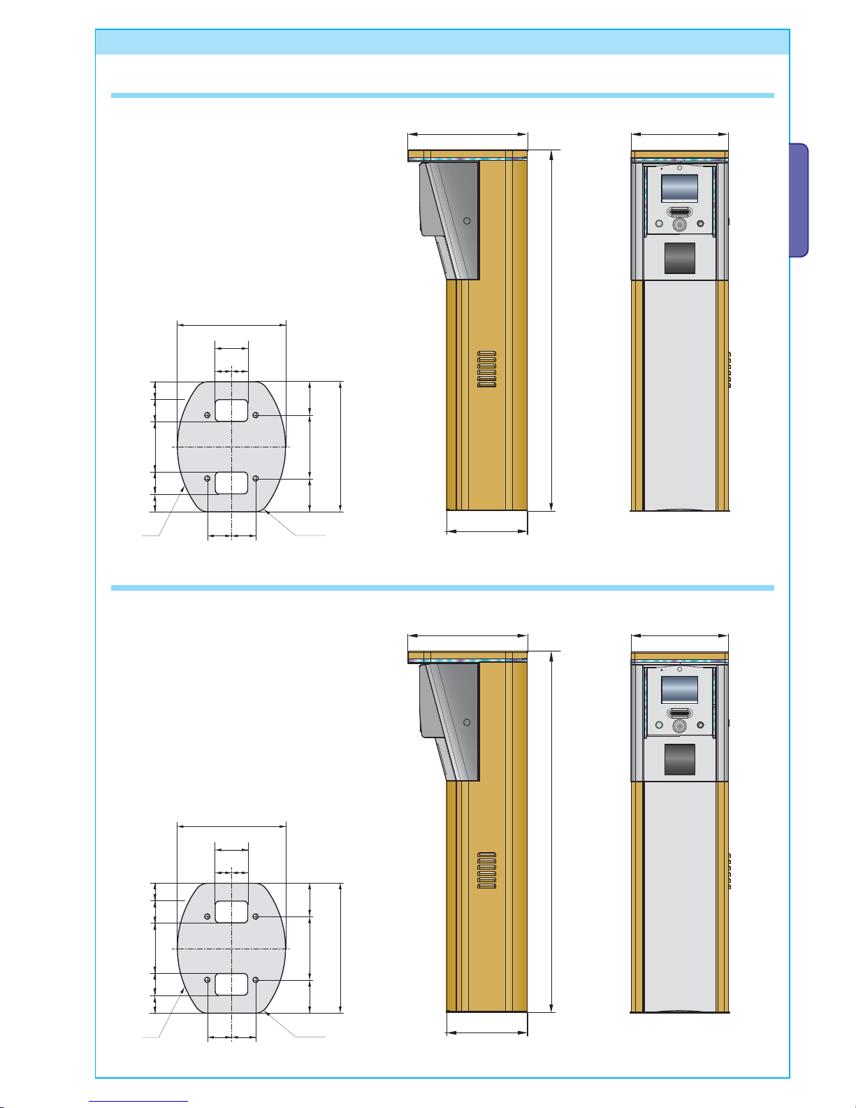
5 Overall dimensions and anchoring bases
Entry unit
Exit unit
Anchoring base
Anchoring base
Page 10

º
(mm)
p.
10
10 -
Manual code:
119G F88
119 GF 88 ver.
1.0
1.0 05/2012
© CAME Cancelli Automatici S.p.A . - The data and information in this manual may be updated at any time by Came Cancelli Automatici S.p.A . which is under no obligation to notify said updates.
ENGLISH
Automatic cash register
Page 11

PLQ
PD[Ɠ
p.
11
11 -
Manual code:
119G F88
119 GF 88 ver.
1.0
1.0 05/2012
© CAME Cancelli Automatici S.p.A . - The data and information in this manual may be updated at any time by Came Cancelli Automatici S.p.A . which is under no obligation to notify said updates.
ENGLISH
6 Sample installation scheme
The image shown below shows a sample, system installation layout with side-by-side entry/exit lanes; also shown are the
measurements among the system components. These must be respected for the system to work properly.
ENTRY
EXIT
Entry detection coil
Exit detection coil
Entry detection coil
Exit detection coil
Entry unit
“Eye System” camera
Exit unit
Barrier
“Eye System” camera
Pit
Barrier
“OCR” license plates camera
“OCR” plates camera
(mm)
Page 12

ŰPP
p.
12
12 -
Manual code:
119G F88
119 GF 88 ver.
1.0
1.0 05/2012
© CAME Cancelli Automatici S.p.A . - The data and information in this manual may be updated at any time by Came Cancelli Automatici S.p.A . which is under no obligation to notify said updates.
ENGLISH
Even the automatic cash-register has been sized taking into account an underlying base that is at least 120 mm high.
The entry and exit units are rated, taking into account an underlying base of at least 120 mm in height and 600 mm in width.
Automatic cash-register user side
Base
Base
Page 13

2 3 4
6
5
7
8
9
11
12
10131415
1
16
p.
13
13 -
Manual code:
119G F88
119 GF 88 ver.
1.0
1.0 05/2012
© CAME Cancelli Automatici S.p.A . - The data and information in this manual may be updated at any time by Came Cancelli Automatici S.p.A . which is under no obligation to notify said updates.
ENGLISH
7 Entry unit / exit unit board - description
1. Traffic light fuse
2. Traffic light connection terminal
3. Fans and heater connection terminals
4. Barrier connection terminals
5. Barrier opening command relay switch
6. Barrier closing command relay switch
7. Optional cards connection terminal
8. Paper sensor connection terminal
9. Door switch connection terminal
10. CPU power supply terminal
11. Operating LED light
12. LED signal lights
13. Input terminal
14. Printer power supply terminal
15. Vcc power supply input
16. Fans and heater fuse
Page 14

1 2 3 4 5 6
7
8
11
10
91213
14
16
15
p.
14
14 -
Manual code:
119G F88
119 GF 88 ver.
1.0
1.0 05/2012
© CAME Cancelli Automatici S.p.A . - The data and information in this manual may be updated at any time by Came Cancelli Automatici S.p.A . which is under no obligation to notify said updates.
ENGLISH
8 Cash-register board - description
1. VAC power supply inputs
2. Inter lighting connection terminal
3. Fans and heater connection terminals
4. Remote alarm output terminal
5. Terminal Restart relay switch
6. Network up sensor terminal
7. Siren sensor alarm connection terminal
8. Cash-register top element LED connection terminal
9. Front board data connection
10. Input status signalling LED light
11. Operating LED light
12. Input terminals
13. Vcc power supply input
14. Ground connection
15. Fans and heater fuse
16. Internal lighting fuse
Page 15

(mm)
p.
15
15 -
Manual code:
119G F88
119 GF 88 ver.
1.0
1.0 05/2012
© CAME Cancelli Automatici S.p.A . - The data and information in this manual may be updated at any time by Came Cancelli Automatici S.p.A . which is under no obligation to notify said updates.
ENGLISH
9 Automatic cash register - installation
Washer
M12 UNI 5588 nut
M12 x 40 UNI 5739 bolt
9.1 Setting up the cash-register base
The following illustrations are mere examples, in that the space required for anchoring the automatic cash-register and
accessories varies depending on the overall dimensions. It is the installer's responsibility to choose the most suited solution.
- Assemble the four anchoring clamps to the plate.
- Dig a pit to house the anchoring plate (see drawing and
measurements at “Overall dimensions and anchoring
bases”) measuring at least 800 x 500 x 500 mm and lay any
required corrugated tubes for connections coming from the
junction pit.
N.B. the number of tubes depends on the type of installation
and accessories used.
- Remove any protruding nuts or washers, position the cabinet
onto the base and fasten it.
Note: install the cabinet so that the inspection hatch faces the
direction shown in the defi ned system diagram.
- Fill the pit with concrete* and sink in the anchoring base (=
plate + anchor brackets). Make sure the corrugated tubes pass
through the specifi c hole in the plate and they do not fi ll with
concrete. The base must be perfectly level, clean and with the
bolt threading completely on the surface.
Wait at least 24 hrs for everything to solidify.
*SUGGESTED CEMENT CHARACTERISTICS
The cement must be slump resistant tested by lowering the
Abrams cone by between 4 and 7 cm (for a conical shaft die 30
cm tall, with 10 cm diameter in the high part and 20 cm in the
low part) and the fi lling of which must be done in four layers.
BONDING AGENTS: Use artifi cial Portland cement with no CPA
325 type constituents.
AGGREGATES: 10/20 caliber and composed of either clay and
salt free limestone or silicon.
DOSAGE: 350 Kg/m³ .
Page 16

p.
16
16 -
Manual code:
119G F88
119 GF 88 ver.
1.0
1.0 05/2012
© CAME Cancelli Automatici S.p.A . - The data and information in this manual may be updated at any time by Came Cancelli Automatici S.p.A . which is under no obligation to notify said updates.
ENGLISH
Fence off the site and follow all safety
prescriptions for mechanical moving
vehicles. Danger Tilting
- Hitch three steel cables with hooks, on the end that can hoist
at least 250 kg, to the eyelets on the head of the central element.
- Pull the cable taut with a mechanical arm and then hoist the
central element and place it above the base.
- Slowly lower the central element, and centre the holes at the
base until it is resting.
- Remove all harnesses.
- Position and lock the 10 issued bolts into place at the base of
the central element.
The automatic cash-register is
supplied in three disassembled parts:
• the base
• the central element
• the closing element
Base
Closing element
Central element
9.2 Mounting the automatic cash register
Page 17

p.
17
17 -
Manual code:
119G F88
119 GF 88 ver.
1.0
1.0 05/2012
© CAME Cancelli Automatici S.p.A . - The data and information in this manual may be updated at any time by Came Cancelli Automatici S.p.A . which is under no obligation to notify said updates.
ENGLISH
- Place the upper element atop the central one and fasten it by tightening
the nine issued bolts.
- Inside the upper compartment, on the left side, connect the
power supply cable coming from the base into its corresponding
terminal.
- Plug the LED connector into the upper element on the left
side of the cash register.
9.3 ETHERNET power supply and connection
Page 18

p.
18
18 -
Manual code:
119G F88
119 GF 88 ver.
1.0
1.0 05/2012
© CAME Cancelli Automatici S.p.A . - The data and information in this manual may be updated at any time by Came Cancelli Automatici S.p.A . which is under no obligation to notify said updates.
ENGLISH
The upper right-hand compartment of the cash-register, is set
up for a back up generator in case of power outages.
- Unplug the upper cable of the relative connection.
- Make the ground connection.
- Inside the upper compartment, on the left-hand side, connect
the Ethernet cable to its socket.
9.4 Installing a back up generator (optional)
Page 19

p.
19
19 -
Manual code:
119G F88
119 GF 88 ver.
1.0
1.0 05/2012
© CAME Cancelli Automatici S.p.A . - The data and information in this manual may be updated at any time by Came Cancelli Automatici S.p.A . which is under no obligation to notify said updates.
ENGLISH
- Place the backup generator on the lower shelf.
- Plug the end of the disconnected cable to the back of the back
up generator.
- Plug an additional cable into the back of the back up generator.
- Plug the end of the additional cable in to the proper socket on
the power supply bracket.
- Once the electrical connections are made, to start the
automatic cash-register, raise the two switches on the cashregister's control panel, in the upper compartment.
9.5 Switching on
Page 20

(mm)
p.
20
20 -
Manual code:
119G F88
119 GF 88 ver.
1.0
1.0 05/2012
© CAME Cancelli Automatici S.p.A . - The data and information in this manual may be updated at any time by Came Cancelli Automatici S.p.A . which is under no obligation to notify said updates.
ENGLISH
10.1 Setting up the entry unit and exit unit bases
The following illustrations are mere examples, in that the space required for anchoring the entry/exit unit and accessories varies depending on the overall dimensions. It is the installer's responsibility to choose the most suited solution.
- Assemble the four anchoring clamps to the plate.
- Dig a pit to house the anchoring plate (see drawing and
measurements at “Overall dimensions and anchoring bases”)
measuring at least 350 x 300 x 250 mm and lay any required
corrugated tubes for connections coming from the junction pit.
N.B. the number of tubes depends on the type of installation
and accessories used.
- Remove any protruding nuts or washers, position the cabinet onto the base and
fasten it.
Note: install the cabinet with the inspection fl ap facing an easily accessible direction.
- Fill the pit with concrete* and sink in the anchoring base (= plate +
anchor brackets). Make sure the corrugated tubes pass through the
specifi c hole in the plate and they do not fi ll with concrete. The base
must be perfectly level, clean and with the bolt threading completely
on the surface.
Wait at least 24 hrs for everything to solidify.
10 Entry unit - exit unit - installing
M12 UNI 5588 nut
M12 x 40 UNI 5739 bolt
Washer
*SUGGESTED CEMENT CHARACTERISTICS
The cement must be slump resistant tested by lowering the Abrams cone by
between 4 and 7 cm (for a conical shaft die 30 cm tall, with 10 cm diameter in
the high part and 20 cm in the low part) and the fi lling of which must be done in
four layers.
BONDING AGENTS: Use artifi cial Portland cement with no CPA 325 type
constituents.
AGGREGATES: 10/20 caliber and composed of either clay and salt free limestone
or silicon.
DOSAGE: 350 Kg/m³ .
Page 21

L3 L4 L5 L6
p.
21
21 -
Manual code:
119G F88
119 GF 88 ver.
1.0
1.0 05/2012
© CAME Cancelli Automatici S.p.A . - The data and information in this manual may be updated at any time by Came Cancelli Automatici S.p.A . which is under no obligation to notify said updates.
ENGLISH
11.1 Connecting coils
11.2 Connecting barriers
- On the left side of the post, find the bi-channel sensor, then
connect up the coils (metal mass detector sensors).
Entry coil
Exit coil
- Remove the container cover to access the electrical board
on the post.
11 Entry unit - exit unit - electrical connections
Page 22

NF1 L 1 L 2
2A 3 2B 4 5 10
p.
22
22 -
Manual code:
119G F88
119 GF 88 ver.
1.0
1.0 05/2012
© CAME Cancelli Automatici S.p.A . - The data and information in this manual may be updated at any time by Came Cancelli Automatici S.p.A . which is under no obligation to notify said updates.
ENGLISH
11.3 Traffic light connections
- On the board, find the connection to barriers terminal (see
entry - exit unit board), then make the connections.
- Find the board on the available parking space display
connection terminal (see entry - exit unit board) and make the
connections.
230 V a.c. output
!6!),!",%
&5,,
Page 23

p.
23
23 -
Manual code:
119G F88
119 GF 88 ver.
1.0
1.0 05/2012
© CAME Cancelli Automatici S.p.A . - The data and information in this manual may be updated at any time by Came Cancelli Automatici S.p.A . which is under no obligation to notify said updates.
ENGLISH
11.4 Power supply
- Find the power supply terminal and make the connection.
- Make the mass connections.
- Position and fasten the cover.
Page 24

p.
24
24 -
Manual code:
119G F88
119 GF 88 ver.
1.0
1.0 05/2012
© CAME Cancelli Automatici S.p.A . - The data and information in this manual may be updated at any time by Came Cancelli Automatici S.p.A . which is under no obligation to notify said updates.
ENGLISH
11.5 ETHERNET connection
11.6 Switching on
11.7 Status signal LED
- At the lower end of the post, connect the Ethernet cable to
its socket.
- Once all electrical connections are made, to start the entry
and exit units press the switch on the left side of the unit.
There is an LED light atop the entry and exit units to show colourcoded status.
- Blue with changing brightness_Standing by;
- Blue_Active with vehicle present
- White_Undergoing maintenance
- Red fl ashing_Out of order/Alarm
Status signal LED
Page 25

p.
25
25 -
Manual code:
119G F88
119 GF 88 ver.
1.0
1.0 05/2012
© CAME Cancelli Automatici S.p.A . - The data and information in this manual may be updated at any time by Came Cancelli Automatici S.p.A . which is under no obligation to notify said updates.
ENGLISH
12 Manned manual cash register - installation
- On the back of the manned cash-register there is a removable
cover which can be removed by loosening the four screws.
The manned cash-register features high connectivity levels with peripherals that boost the potential of this all-in-one solution.
It provides complete management of cash-register stations in all types of business premises, and that's not all. Other possible
installations include omni-directional barcode scanners, magnetic card readers and optical units via USB. If also features an
internal socket for installing a Compact Flash board (on the secondary IDE channel) and can be fitted with an MLC / SLC SSD (Solid
State Disk) unit. The manned cash-register is full of communication interfaces to enable it to connect to secondary devices. Its
handy back cover plate neatly hides all cables.
It boasts three serial ports (outer access ones), six 2.0 USB ports (5 of which are external), one LAN RJ45 port, one Digital I/O port
on RJ11 for a 12V change dispensing drawer, one VGA port, one PS/2 port and one audio Line Out port.
11.8 LED input index on entry - exit unit board
LED LIST STATUS OF COMPONENT
INPUT 1 Coil 1 status
INPUT 2 Coil 2 status
INPUT 3 Use depends on how system is used
INPUT 4 Use depends on how system is used
INPUT 5 Use depends on how system is used
INPUT 6 Barrier status (open/closed)
Removable
back cover
Page 26

p.
26
26 -
Manual code:
119G F88
119 GF 88 ver.
1.0
1.0 05/2012
© CAME Cancelli Automatici S.p.A . - The data and information in this manual may be updated at any time by Came Cancelli Automatici S.p.A . which is under no obligation to notify said updates.
ENGLISH
- Restore the cover by tightening the four screws.
- Make the connections as shown in the figure.
- Make the connections on the back of the roboticket reader/printer, as shown in the figure.
POS connector
Power supply
Printer/Roboticket
connector
ETHERNET
connector
Drawer
connector
Manual barcode
reader connection
12.1 Roboticket Connections
Manual, manned cash
register connection.
Power supply
Page 27

p.
27
27 -
Manual code:
119G F88
119 GF 88 ver.
1.0
1.0 05/2012
© CAME Cancelli Automatici S.p.A . - The data and information in this manual may be updated at any time by Came Cancelli Automatici S.p.A . which is under no obligation to notify said updates.
ENGLISH
THIS PAGE LEFT INTENTIONALLY BLANK
Page 28

CAME
CAME
Franc e
France
S.a .
S.a. FRANCE
7, Rue Des Haras
Z.i. Des Hautes Patures
92737
Nante rre C edex
Nanterre Cedex
(+33) 0 825 825 874
(+33) 1 46 13 05 00
GERMANY
CA ME Gm bh Se efeld
CAME Gmbh Seefeld
Akazienstrasse, 9
16356
Seefe ld
Seefeld Bei Berlin
(+49) 33 3988390
(+49) 33 39883985
CAME A utoma tisme s S.a.
CAME Automatismes S.a. FRANCE
3, Rue Odette Jasse
13015
Marse ille
Marseille
(+33) 0 825 825 874
(+33) 4 91 60 69 05
U.A.E.
CAME Gulf Fze
CAME Gulf Fze
Offi ce No: S10122a2o210
P.O. Box 262853
Jebel Ali Free Zone -
Dubai
Dubai
(+971) 4 8860046
(+971) 4 8860048
CAME A utoma tismo s S.a.
CAME Automatismos S.a. SPAIN
C/juan De Mariana, N. 17-local
28045
Madr id
Madrid
(+34) 91 52 85 009
(+34) 91 46 85 442
RUSSIA
CAME Rus
CAME Rus
Umc R us Ll c
Umc Rus Llc
Ul. Otradnaya D. 2b, Str. 2, offi ce 219
127273,
Mosco w
Moscow
(+7) 495 739 00 69
(+7) 495 739 00 69 (ext. 226)
CAME Unite d Kin gdom Ltd.
CAME United Kingdom Ltd. GREAT BRITAIN
Unit 3 Orchard Business Park
Town Street, Sandiacre
Notti ngham
Nottingham - Ng10 5bp
(+44) 115 9210430
(+44) 115 9210431
PORTUGAL
CAME Portu gal
CAME Portugal
Ucj P ortug al Un ipess oal L da
Ucj Portugal Unipessoal Lda
R
ua Liebig, nº 23
2830-141
Barre iro
Barreiro
(+351) 21 207 39 67
(+351) 21 207 39 65
CAME Group Bene lux S.a.
CAME Group Benelux S.a. BELGIUM
Zoning Ouest 7
7860
Less ines
Lessines
(+32) 68 333014
(+32) 68 338019
INDIA
CAME India
CAME India
Autom ation Solu tions Pvt. Ltd
Automation Solutions Pvt. Ltd
A - 10, Green Park
110016 -
New D elhi
New Delhi
(+91) 11 64640255/256
(+91) 2678 3510
CAME A meric as Autom ation Llc
CAME Americas Automation Llc U.S.A
11345 NW 122nd St.
Medle y
Medley, FL 33178
(+1) 305 433 3307
(+1) 305 396 3331
ASIA
CA ME Asi a Pac ific
CAME Asia Pacific
60 Alexandra Terrace #09-09
B
lock C, The ComTech
118 502
Singa pore
Singapore
(+65) 6275 0249
(+65) 6274 8426
CAME Gmbh
CAME Gmbh GERMANY
Kornwestheimer Str. 37
70825
Korn tal
Korntal Munchingen Bei Stuttgart
(+49) 71 5037830
(+49) 71 50378383
CAME Cance lli Au tomat ici S.p.a.
CAME Cancelli Automatici S.p.a. ITALY
Via Martiri Della Libertà, 15
31030
Doss on Di Casi er
Dosson Di Casier (Tv)
(+39) 0422 4940
(+39) 0422 4941
Informazioni Commerciali 800 848095
ITALY
CAME Sud s .r.l.
CAME Sud s.r.l.
Via F. Imparato, 198
Centro Mercato 2, Lotto A/7
80146
Napo li
Napoli
(+39) 081 7524455
(+39) 081 7529190
CAME Service Italia S.r.l.
CAME Service Italia S.r.l. ITALY
Via Della Pace, 28
31030
Doss on Di Casi er
Dosson Di Casier (Tv)
(+39) 0422 383532
(+39) 0422 490044
Assis tenza Tecn ica 8 00 29 5830
Assistenza Tecnica 800 295830
ITALY
CAME Globa l Uti litie s s.r.l .
CAME Global Utilities s.r.l.
V
ia E. Fermi, 31
20060
Gessa te
Gessate (Mi)
(+39) 02 95380366
(+39) 02 95380224
09_2011
www.came.com www.came.it
Engli sh
English - Manual code:
119G F88
119 GF 88
ver.
1.0
1.0 05/2012 © CAME Cancelli Automatici S.p.A.
The data and information in this manual may be updated at any time by Came Cancelli Automatici S.p.A. which is under no obligation to notify said updates.
 Loading...