

Page 1

GUARDIAN SERIES
FULL-HEIGHT
TURNSTILE
INSTALLATION MANUAL
PSHPS01 – PSHPS07 – PSHPSD7
English
EN
Page 2

EN
ENGLISH
WARNING!
Important instructions for the safety of people:
READ CAREFULLY!
Foreword
• Use of the products must be restricted to its intended use
(i.e. that for which it was expressly built for). Any other use is
to be considered dangerous. Came Cancelli Automatici S.p.A.
is not liable for any damage resulting from improper, wrongful
ENGLISH
or unreasonable use • Keep these warnings with the installation and use manuals issued with the automated system.
Before installing
(preliminary check: in case of a negative
outcome, do not proceed before having
complied with the safety obligations)
• Make sure that the parts you intend to automate are in
good working order, and that they are properly balanced
and aligned. Also, make sure that proper mechanical stops
are already in place • If the operator will be installed at a
height of less than 2.5 m from the ground or other access
level, check whether you will need any protections and/or
warnings • Any gate leaves, fi tted with pedestrian entrances,
onto which you will install an operator, must have a blocking
mechanism when the gate is in motion • Make sure that the
opening of the automated gate is not an entrapment hazard
as regards any surrounding fi xed parts • Do not mount the
operator upside down or onto any elements that may fold
under its weight. If needed, add suitable reinforcements at
the points where it is secured • Do not install onto gates on
either an upward or downward slope (i.e. that are not on fl at,
level ground) • Check that any lawn watering devices will not
wet the gearmotor from the bottom up.
are working properly • Where necessary and in plain sight,
apply the Warning Sings (e.g. gate plate).
Special instructions and
advice for users
• Keep the gate’s area of operation clean and clear of any
obstacles. Trim any vegetation that may interfere with the
photocells • Do not allow children to play with the fi xed command devices, or in the gate’s area of operation. Keep any
remote control devices (i.e. transmitters) away from the children as well • Frequently check the system, to see whether
any anomalies or signs of wear and tear appear on the moving
parts, on the component parts, on the securing points, on the
cables and any accessible connections. Keep any joints (i.e.
hinges) lubricated and clean, and do the same where friction may occur (i.e. slide rails) • Perform functional tests on
photocells and sensitive edges, every six months. Keep glass
panels constantly clean (use a slightly water-moistened cloth;
do not use solvents or any other chemical products) • If the
system requires repairs or modifi cations, release the operator
and do not use it until safety conditions have been restored
• Cut off the power supply before releasing the operator for
manual openings. See instructions • Users are FORBIDDEN
to carry out ANY ACTIONS THAT THEY HAVE NOT BEEN
EXPRESSLY ASKED TO DO OR SO INDICATED in the manuals. Any repairs, modifi cations to the settings and extraordinary maintenance MUST BE DONE BY THE TECHNICAL
ASSISTANCE STAFF • On the periodic maintenance log, note
down the checks you have done.
Installation
• Carefully section off the entire site to prevent unauthorised
access, especially by minors and children • Be careful when
handling operators that weigh more than 20 Kg (see installation manual). In such cases, employ proper weight handling
safety equipment • All opening commands (e.g. buttons, key
selectors, magnetic detectors, etc.) must be installed at least
1.85 m from the gate’s area of operation perimeter - or where
they cannot be reached from the outside of the gate. Also,
the direct commands (e.g. push button, or proximity devices,
etc.) must be installed at a height of at least 1.5 m and must
not be accessible to the public • All ‘maintained action’ commands, must be placed where the moving gate leaves, transit
areas and driveways are completely visible • If missing, apply a permanent label that shows the position of the release
mechanism • Before delivering to the client, verify that the
system is EN 12453 (impact test) standard compliant. Make
sure that the operator has been properly adjusted and that the
safety and protection devices, as well as the manual release
Special instructions and
advice for all
• Avoid working near the hinges or moving mechanical parts
• Stay clear of the gate’s area of operation when in motion •
Do not resist the direction of movement of the gate; this may
present a safety hazard • At all times be extremely careful
about dangerous points that must be indicated by proper
pictograms and/or black and yellow stripes • When using
a selector or command in ‘maintained action’ mode, keep
checking that there are no people in the area of operation of
the moving parts. Do this until you release the command •
The gate may move at any time without warning • Always cut
the power when cleaning performing maintenance.
CAME cancelli automatici s.p.a.
Via Martiri della Libertà, 15
31030 Dosson di Casier
TREVISO - ITALY
www.came.it - info@came.it
Page 3

General conditions of sale
1. GENERAL POINTS
These general conditions shall apply to all purchase agreements for Came Cancelli Automatici SpA materials, hereinafter called “the
company”.
2. OFFERS AND QUOTATIONS
The company’s quotations are valid for a 30-day period at the most starting from the date they are sent.
3. ORDERS
The sale agreement is executed once the written order is confirmed by Came Cancelli Automatici Spa or when the order is fulfilled by
the company. Orders that are addressed, and signed by clients, to Came Cancelli Automatici SpA are deemed to be firm and irrevocable
for 30 days starting from the date they are received by the company. Any change or addition to the single provisions of these general
conditions or single provisions of the order which was originally addressed by the client, shall have no validity unless otherwise approved
in writing by the company. For any changes to the order, the company reserves the right to cancel both the changes an the original order.
The delivery date for the goods appearing on the orders is always and in any case exclusively indicative, and any delays of such term may
never justify claims for compensation or cancellation of contract.
Particularly, the company reserves the right to extend the delivery terms or cancellation of order in the event of: force majeure or events
that are beyond the control of the company; change of the Client’s legal status; difficulty in sourcing raw materials and component parts.
4. DELI VERY AN D FORWARDING
The place of production or registered office of the company shall be the place of fulfilment for delivery. The cost and risk of the travelling
goods is borne by the buyer ex works, pursuant to the 2000 incoterms. Unless otherwise agreed, the company establishes, for and on
behalf of the client, the type of shipping, the travel route and type of carrier. The company reserves the right to carry out partial deliveries
and fulfilment of orders, thereby issuing a separate invoice each time: in this case all partial deliveries shall be autonomously invoiced and
the terms of payment shall begin as of the date on each invoice; the client may not, therefore, defer payment of partial orders, until the last
deliver y is made as concerns the original order.
5. PRICES AND PRICE LISTS
The prices are intended for goods delivered free to the company’s registered office, not including VAT, with normal packaging, and not
including forwarding expenses. Any reference to list prices shall refer to the latest price list published by the company, which theretofore
cancels any previous price lists.
6. PAYMENTS
Non-payment within the established terms, shall result in the application of interest pursuant to Lgs. Decr. 09/10/2002 n. 231 and
subsequent amendments and upgrades, with any possible greater damage unprejudiced. Any delay in payment, shall mean that the client
shall owe the company, any losses due to exchange rates. The client may not advance any demands nor raise any exceptions as concerns
the company, unless after having paid the goods it purchased. The company reserves the right to block all shipping and supply orders
underway in the face of any irregularities in the payments, without need of prior notice nor compensatory damages of any kind.
7. RETURNS AND CLAIMS
All claims must be filed in writing within 8 days of receiving the goods, whether such claims refer to the quantity or quality of the delivered
goods. Returned goods shall be accepted by company only following a written agreement, and only for new and packaged goods. Any
returned goods must be complete of their relative transport documents, showing the company’s written authorisation to accept the
returned goods including the quality and quantity of the returned goods.
The returned goods shall not be accepted by the company unless carried out in the above mentioned manner and, especially, returned
goods shall not be accepted if received at any of the company’s premises.
8. GUARANTEE
The company guarantees the proper functioning of the products that it provides, as per the technical characteristics that are expressly
shown on its products’ technical sheets. The guarantee shall not apply in the case of any environmental interferences of any nature, which
could cause disturbances in the functioning of any existing or future installations (radio frequencies – proximity of electric power lines…).
The guarantee does not cover the normal wear and tear of the equipment, or mistakes made during the mounting phase or due to
maintenance flaws, and in any case it does not cover any cases in which flaws in the functioning can be traced back to factors stemming
from anything other than manufacturing.
The deadlines for filing a claim for any flaws or for the statute of limitations for actions to which the buyer is entitled are those foreseen by
Italian law. The company at its own leisure, may decide to withdraw any goods supplied which it has ascertained as faulty, or decide to
repair said ascertained flaws. The client may not request to be compensated for any indirect damages, missed gains, production losses,
and in any case may not expect as compensation any sums greater than the value of the supplied components or products.
9. REPAIRS
Repairs to purchased items request by the client shall be carried out by the company following an agreement on the price of said repairs.
In any case the expenses for labour and shipping (roundtrip) shall be borne by the client.
10. RESE RVATION OF TITLE
It is expressly agreed that, any delivered goods remain owned by the company until the client pays the entire balance, regardless of who
is in possession of said goods. Transport expenses and any other expenses needed to retrieve the equipment, therein including any
extraordinar y expenses as well as any repeatable ones, shall be borne by the client.
11. APPLICCABLE L AW – SET TLEMENT OF ANY DIS PUTES Any arising dispute resulting from the sale agreement, shall be settled
according to the Italian law, thereby excluding any other law and in supplement to the Vienna Convention on the international sale of
goods. All disputes shall be subject to Italian jurisdiction and come under the exclusive competence of the Tribunal of Treviso, Italy.
12. PROVISION S ON THE SAFEGUARDING OF PERSONAL DATA .
Pursuant to current legislation for the safeguarding of personal data, clients are aware that their personal data is inputted into the
company’s databank, which is necessary for the proper carrying out of the contractual relationship and for compliance with certain
provisions of law, as well as for purposes of statistics, promotion, marketing, commercial, credit protection, management and transfer of
the same .
The personal data of the buying party are processed through automated and paper-based tools by authorised persons, by using safety
procedures designed to guarantee confidentiality. The personal data of the client may by shared with Public Bodies, companies of the
group, credit recovery firms, or consortiums or associations with business scopes, market research scopes, or marketing scopes. The
data processor shall be the company, and the client may address said company to uphold their own rights as per law. To this end the
buying party is aware that at any time it may access its personal data, ask that it be updated, corrected and /or prohibit it from being used.
ENGLISH
Page 4

2
119G305 5
1.0
“IMPORTANT SAFETY INSTRUCTIONS FOR INSTALLATION”
“WARNING: WRONG INSTALLATION MAY CAUSE SERIOUS INJURY, FOLLOW ALL INSTALLATION INSTRUCTIONS”
“THIS MANUAL IS EXCLUSIVELY MEANT FOR PROFESSIONAL INSTALLERS OR OTHER COMPETENT PERSONS”
1 Legend of symbols
This symbol shows parts to be read carefully.
This symbol shows parts related to safety.
This symbol shows what to tell users.
ENGLISH
This symbol shows exclusively the electro-mechanical models.
2 Conditions of use
2.1 Intended use
The GUARDIAN electromechanical turnstile is designed to make wide entrances safe and secure, even without manning the
entrance, and in highly frequented contexts like stadiums, airports, stations, public buildings and in any other places where highvolume flows need to be regulated and/or selected.
Any installation or use other than that shown in this manual is prohibited.
3 Reference Legislation
The product being described herein complies with the following legislation: see compliance statement.
4 Description
4.1 Turnstile
This product is designed and built by CAME Cancelli Automatici S.p.A. in compliance with the current safety legislation.
Guaranteed 24 months unless tampered with.
GUARDIAN is a mono or bidirectional turnstile featuring a “full-height”, safety transit-entrance; its galvanised, varnished, steel structure consists of two lateral, supporting columns and an transom – all fi tted with opening casings to allow for cables and any cards
and/or additional electronics to be used.
The rotating, central column is made of AISI 304 stainless steel with 3 sets of arms, also made of polished, 40 mm diameter steel.
Each set of arms is directly welded to a profi le secured to the rotating fl ange. The safety grates are made of perforated sheets of
AISI 304
It works to allow one person at the time to transit, in the desired direction. Via the device a command is activated to release the
mechanism and manually push the rotor arms until the mechanical brake is activated, which slows the rotor arms down to its still
position until a new command is given. The mechanism has an antirotation system that is activated once the rotor arms extend
beyond 60°.
The complete range:
PSHPS01 “Full height” mono-directional, single opening, mechanical turnstile. Body made of varnished, galvanised steel, with
hydraulic brake.
PSHPS07 “Full height” , bidirectional, single opening, electromechanical turnstile. Body made of varnished, galvanised steel, with
hydraulic brake, electronic board, plus two-way LED traffi c-lights.
PSHPSD7 Independently managed , “full height” bidirectional, double opening, electromechanical turnstile. Body made of varnished,
galvanised steel, with hydraulic brakes, electronic boards and two-way LED traffi c lights.
4.2 Technical data
PSHPS01
Protection rating: IP44
Weight: 350 kg
#
#
#
#
PSHPS07
Electrical panel power: 230V AC 50/60Hz
Accessories power: 24V AC
Power Draw: 223mA
insulation class: II
Protection rating: IP44
Weight: 350 kg
#
#
PSHPSD7
Electrical panel power: 230V AC 50/60Hz
Accessories power: 24V AC
Power Draw: 446mA
insulation class: II
Protection rating: IP44
Weight: 650 kg
#
#
1.0 10/2009 © CAME cancelli automatici s.p.a. - The data and information reported in this installation manual are susceptible to change at any time and without obligation on CAME cancelli automatici s.p.a. to notify users.
119 G3 05 5 ver.
- Manual code:
Pag.
Page 5

3
119G305 5
1.0
4.3 Description of parts
1) Suppor ting column
2) Transom
3) Comb rotor
4) Wings with arms
5) Wings
6) Column covers
7) Safety grate
8) Transom cover
9) Mechanism
10) Control panel
11) Direction light (Stop/Go light)
8
8
9
9
10
10
2
5
5
4
4
11
11
2
6
6
7
7
ENGLISH
4.4 Dimensions
(mm)
The data and information reported in this installation manual are susceptible to change at any time and without obligation on CAME cancelli automatici s.p.a. to notify users.
1500
3
3
7
7
4
4
6
6
1
1
2330
7
7
5
5
2250
2330
© CAME cancelli automatici s.p.a. -
1.0 10/2009
119 G3 05 5 ver.
:
Manual code
-
Pag.
Single Double
1420
1420
Page 6

4
119G305 5
1.0
5 Installing a single opening
Only skilled, qualified staff must perform the installation, in full compliance of the current legislation.
5.1 Preliminary checks
Before installing the automated device, please:
• Set up a proper omnipolar cut-off device, with contacts more than 3 mm apart, and power source isolation;
• Set up proper tubing and conduits for the electrical cables to go through with enough protection from any mechanical
damage;
ENGLISH
•
Check that any connections within the container (made to give continuity to the protection circuit) have additional isolation
compared to the other internal power conductors.
• Check that the transit entrance area in a proper state and free of any slumps, otherwise apply the required (L=1800 mm x
L=1600 mm x H=120 mm) RCK300 cement base, which ensures proper securing of the turnstile.
5.2 Tools and materials
Make sure you have all the tools and materials needed to carry out the installation in total safety and in compliance with current
legislation. The figures shows examples of installers’ tools.
5.3 Standard installation
1) Automated operator
2) Fence
3) Junction pit
4) Direction indicator
1
2
4
2
1.0 10/2009 © CAME cancelli automatici s.p.a. - The data and information reported in this installation manual are susceptible to change at any time and without obligation on CAME cancelli automatici s.p.a. to notify users.
119 G3 05 5 ver.
3
- Manual code:
Pag.
Page 7
5
119G305 5
1.0
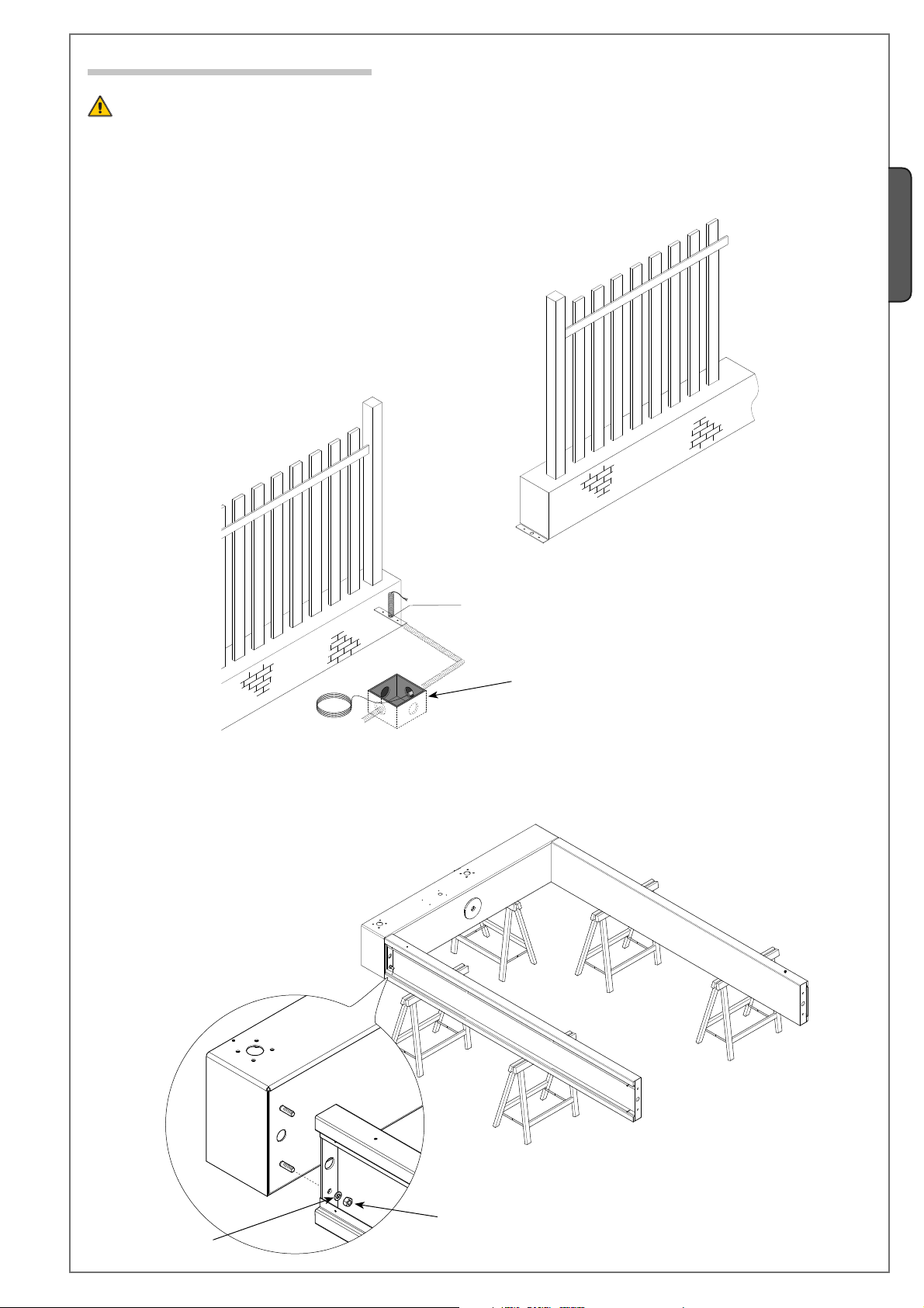
5.4 Installing the turnstile
Warning: to install this at least two or three people are needed. Use hoisting equipment to move and position the turnstile
When securing, the turnstile may be unstable and could tip over, so be careful not to lean onto it until securing in complete.
Lay the corrugated tubes to make the connections coming from the junction pit.
N.B. the number of tubes depends on the type of installation and accessories being fi tted.
ENGLISH
Secure the supporting columns to the traverse.
The data and information reported in this installation manual are susceptible to change at any time and without obligation on CAME cancelli automatici s.p.a. to notify users.
© CAME cancelli automatici s.p.a. -
Ø12 mm
Cable junction pit
1.0 10/2009
119 G3 05 5 ver.
:
Manual code
-
UNI1751 Ø10 washer
Pag.
UNI5587 M8 Nut
Page 8
6
119G305 5
1.0
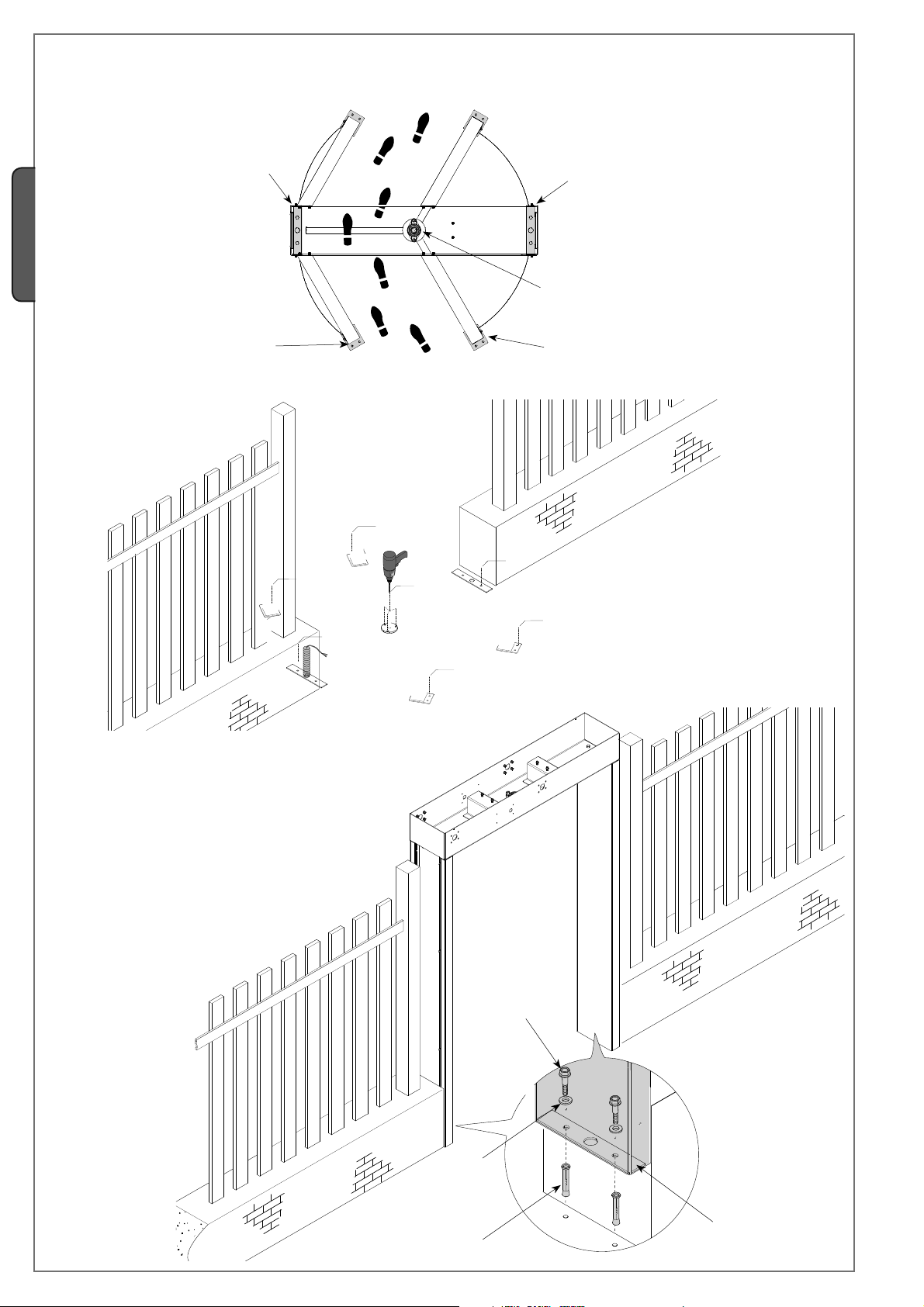
Use the template to precisely mark the holes for securing the columns and wings.
Drill the carefully marked holes using a 12 mm bit and secure the columns using appropriate 8 mm bolts.
ENGLISH
Holes for the supportino column
Holes for the wing
Ø12 mm
Ø12 mm
Holes for the supportino column
Holes for the lower pivot pin
Holes for the wing
Ø12 mm
Ø12 mm
Ø12 mm
Ø12 mm
Ø12 mm
bolt
1.0 10/2009 © CAME cancelli automatici s.p.a. - The data and information reported in this installation manual are susceptible to change at any time and without obligation on CAME cancelli automatici s.p.a. to notify users.
Washer
Dowel plug
Base plate
119 G3 05 5 ver.
- Manual code:
Pag.
Page 9

7
119G305 5
1.0
Assemble the rotor arms, join and secure the single arms to the side with bolts and to the reinforcing triangle with the washers, nuts
and bolts using the issued T-driver.
Finally, insert the caps using a plastic or wooden mallet and striking them on their perimeter so as not to damage them.
1)
UNI5933 M8x20 screws
ENGLISH
Hexagonal, T-iron.
The data and information reported in this installation manual are susceptible to change at any time and without obligation on CAME cancelli automatici s.p.a. to notify users.
2)
Reinforcing triangle
UNI5587 M10 nur
UNI1751 Ø10 washer
Cap
© CAME cancelli automatici s.p.a. -
1.0 10/2009
119 G3 05 5 ver.
:
Manual code
-
Pag.
3)
Page 10

1
2
8
119G305 5
1.0
Insert the upper, centre swivel-pin of the rotor arms into the hole in the traverse piece, insert the Seeger ring into the swivel-pin
housing and leave the rotor arms hanging from the traverse piece (suspended by the Seeger ring).
ENGLISH
Hole
1
Upper-centre swivel-pin
Seger ring
2
3
Insert the dowel plugs into the holes, insert the lower pivot under the lower central disk and secure it using the bolts.
1
2
3
Dowel plug
Bolt
Washer
1.0 10/2009 © CAME cancelli automatici s.p.a. - The data and information reported in this installation manual are susceptible to change at any time and without obligation on CAME cancelli automatici s.p.a. to notify users.
119 G3 05 5 ver.
Lower central ring
Lower pivot
- Manual code:
Pag.
Page 11

9
119G305 5
1.0
Secure the arms to the frames using washers and nuts. Then, insert the caps.
2)
1)
ENGLISH
Secure the armed frame to the centre of the traverse piece using nuts and washers. On the bottom secure it using appropriate
plugs and bolts.
The data and information reported in this installation manual are susceptible to change at any time and without obligation on CAME cancelli automatici s.p.a. to notify users.
© CAME cancelli automatici s.p.a. -
1.0 10/2009
119 G3 05 5 ver.
:
Manual code
-
Pag.
Page 12

10
119G305 5
1.0
Secure the frames (without arms) to the ends of the traverse piece using nuts and washers. On the bottom use appropriate plugs
and bolts.
UNI1751 Washer
UNI1750 Washer
ENGLISH
UNI5587 M8 Nur
Warning! Position the cage’s upper swing-pin as shown in the drawing to allow mechanism to be inserted.
Bolt
Dowel plug
1.0 10/2009 © CAME cancelli automatici s.p.a. - The data and information reported in this installation manual are susceptible to change at any time and without obligation on CAME cancelli automatici s.p.a. to notify users.
119 G3 05 5 ver.
10 - Manual code:
Pag.
Page 13

11
119G305 5
1.0
Position the mechanism above the upper swing-pin and secure it using nuts and washers.
UNI5587 Nur
UNI1751 Washer
UNI1750 Washer
ENGLISH
The data and information reported in this installation manual are susceptible to change at any time and without obligation on CAME cancelli automatici s.p.a. to notify users.
© CAME cancelli automatici s.p.a. -
1.0 10/2009
119 G3 05 5 ver.
:
Manual code
11 -
Pag.
Electromagnets
Control panel
housing
Page 14

12
119G305 5
1.0
6 Installing a double opening
Only skilled, qualified staff must perform the installation, in full compliance of the current legislation.
6.1 Preliminary checks
Before installing the automated device, please:
• Set up a proper omnipolar cut-off device, with contacts more than 3 mm apart, and power source isolation;
• Set up proper tubing and conduits for the electrical cables to go through with enough protection from any mechanical
damage;
ENGLISH
•
Check that any connections within the container (made to give continuity to the protection circuit) have additional isolation
compared to the other internal power conductors.
• Check that the transit entrance area in a proper state and free of any slumps, otherwise apply the required (L=2600 mm x
L=1600 mm x H=120 mm) RCK300 cement base, which ensures proper securing of the turnstile.
6.2 Tools and materials
Make sure you have all the tools and materials needed to carry out the installation in total safety and in compliance with current
legislation. The figures shows examples of installers’ tools.
6.3 Standard installation
1) Automated operator
2) Fence
3) Junction pit
4) Direction indicator
4
2
1
4
2
1.0 10/2009 © CAME cancelli automatici s.p.a. - The data and information reported in this installation manual are susceptible to change at any time and without obligation on CAME cancelli automatici s.p.a. to notify users.
119 G3 05 5 ver.
3
12 - Manual code:
Pag.
Page 15

13
119G305 5
1.0
6.4 Installing the turnstile
Warning: to install this at least two or three people are needed. Use hoisting equipment to move and position the turnstile
When securing, the turnstile may be unstable and could tip over, so be careful not to lean onto it until securing in complete.
Lay the corrugated tubes to make the connections coming from the junction pit.
N.B. the number of tubes depends on the type of installation and accessories being fi tted.
ENGLISH
Secure the supporting columns to the traverse.
The data and information reported in this installation manual are susceptible to change at any time and without obligation on CAME cancelli automatici s.p.a. to notify users.
© CAME cancelli automatici s.p.a. -
1.0 10/2009
Cable junction pit
119 G3 05 5 ver.
:
Manual code
UNI1751 Ø10 washer
13 -
Pag.
UNI5587 M8 Nut
Page 16

14
119G305 5
1.0
Use the template to precisely mark the holes for securing the columns and wings.
Drill the carefully marked holes using a 12 mm bit and secure the columns using appropriate 8 mm bolts.
ENGLISH
Holes for the supportino column
Holes for the wing
Ø12 mm
Ø12 mm
Ø12 mm
Holes for the supportino column
Holes for the lower pivot pin
Holes for the wing
Ø12 mm
Ø12 mm
Ø12 mm
Ø12 mm
Ø12 mm
Ø12 mm
Ø12 mm
bolt
Washer
Dowel plug
Base plate
1.0 10/2009 © CAME cancelli automatici s.p.a. - The data and information reported in this installation manual are susceptible to change at any time and without obligation on CAME cancelli automatici s.p.a. to notify users.
119 G3 05 5 ver.
14 - Manual code:
Pag.
Page 17

15
119G305 5
1.0
Assemble the rotor arms, join and secure the single arms to the side with bolts and to the reinforcing triangle with the washers, nuts
and bolts using the issued T-driver.
Finally, insert the caps using a plastic or wooden mallet and striking them on their perimeter so as not to damage them. (see
drawings)
Note: set up the single arms to be
assembled along the corresponding rotor
frame. Refer to the reinforcement triangle
or to the distance between the upper disc
and the fi rst of the arms.
A
Reinforcing triangle
1)
ENGLISH
UNI5933
M8x20
screws
2)
Reinforcing triangle
The data and information reported in this installation manual are susceptible to change at any time and without obligation on CAME cancelli automatici s.p.a. to notify users.
© CAME cancelli automatici s.p.a. -
1.0 10/2009
B
UNI5587 M10 nur
UNI1751 Ø10 washer
Hexagonal, T-iron.
Cap
3)
119 G3 05 5 ver.
:
Manual code
15 -
Pag.
Page 18

1
2
16
119G305 5
1.0
Insert the upper, centre swivel-pin of the rotor arms into the hole in the traverse piece, insert the Seeger ring into the swivel-pin
housing and leave the rotor arms hanging from the traverse piece (suspended by the Seeger ring).
Hole
ENGLISH
Seger ring
Upper-centre swivel-pin
Insert the dowel plugs into the holes, insert the lower pivot under the lower central disk and secure it using the bolts.
1.0 10/2009 © CAME cancelli automatici s.p.a. - The data and information reported in this installation manual are susceptible to change at any time and without obligation on CAME cancelli automatici s.p.a. to notify users.
119 G3 05 5 ver.
1
2
3
Dowel plug
Lower central ring
Lower pivot
Bolt
Washer
16 - Manual code:
Pag.
Page 19

17
119G305 5
1.0
Secure the frames (without arms) to the ends of the traverse piece using nuts and washers. On the bottom use appropriate plugs
and bolts.
UNI1751 Washer
UNI1750 Washer
UNI5587 M8 Nur
ENGLISH
Secure the arms to the frames using washers and nuts. Then, insert the caps.
The data and information reported in this installation manual are susceptible to change at any time and without obligation on CAME cancelli automatici s.p.a. to notify users.
1)
2)
Bolt
Dowel plug
© CAME cancelli automatici s.p.a. -
1.0 10/2009
119 G3 05 5 ver.
:
Manual code
17 -
Pag.
Page 20

18
119G305 5
1.0
Secure the frames (without arms) to the ends of the traverse piece using nuts and washers. On the bottom use appropriate plugs
and bolts.
UNI1751 Washer
UNI1750 Washer
ENGLISH
UNI5587 M8 Nur
Warning! Position the cage’s upper swing-pin as shown in the drawing to allow mechanism to be inserted.
Bolt
Dowell Plug
1.0 10/2009 © CAME cancelli automatici s.p.a. - The data and information reported in this installation manual are susceptible to change at any time and without obligation on CAME cancelli automatici s.p.a. to notify users.
119 G3 05 5 ver.
18 - Manual code:
Pag.
Page 21

19
119G305 5
1.0
Position the mechanism above the upper swing-pin and secure it using nuts and washers.
UNI5587 Nur
UNI1751 Washer
UNI1750 Washer
ENGLISH
The data and information reported in this installation manual are susceptible to change at any time and without obligation on CAME cancelli automatici s.p.a. to notify users.
© CAME cancelli automatici s.p.a. -
1.0 10/2009
119 G3 05 5 ver.
:
Manual code
19 -
Pag.
Electromagnets
Control panel
housing
Electromagnets
Control panel
housing
Page 22

20
119G305 5
1.0
7 Electric wiring
Position the control panel inside the traverse piece to then connect to the cables.
Thread the control panel and accessories power cable along the entire height of the column through the hole all the way up the
traverse piece.
Control panel
ENGLISH
Power cable
From the traverse piece, thread the two ends of the fl at wire through the holes on the side of the traverse piece and connect to the
traffi c lights. Connect the central fl at-wire plug to the board socket. (see electrical connections).
Metal
LED stop/go lights
strips
Control
LED stop/go lights
panel
Note: the above descriptions and illustrations refer to the single model. The
double model requires double cabling.
Control
panel
1.0 10/2009 © CAME cancelli automatici s.p.a. - The data and information reported in this installation manual are susceptible to change at any time and without obligation on CAME cancelli automatici s.p.a. to notify users.
119 G3 05 5 ver.
20 - Manual code:
Pag.
Page 23

21
119G305 5
1.0
7.1 Cable type and section
Connection Cable type
230V power supply to control panel
Power supply to accessories 2 x 0,5 mm
FROR CEI
20-22
Cable length
1 < 10 m
3G x 1,5 mm
CEI EN
Control and safety devices 2 x 0,5 mm
50267-2-1
2
2
2
Cable length
10 < 20 m
3G x 2,5 mm
2 x 0,5 mm
2 x 0,5 mm
Cable length
20 < 30 m
2
2
2
3G x 4 mm
2 x 1 mm
2 x 0,5 mm
2
2
2
N.B. If the cable length differs to that shown in the table, determine cable section based on the actual power draw by the connected
devices and according to what is prescribed by law CEI EN 60304-1.
For sequential connections on the same line, length-measurements by the table must be converted on the basis of draw and actual
distances. To connect any products not mentioned in this manual, see documentation provided with said products.
8 Control panel
8.1 General description
The control panel is powered by 230V A.C. on terminals L-N,
with max frequency of 50/60Hz.
The command and control devices and accessories are 24V.
All connections are quick-fuse protected, see table.
The defi nable command and control functionalities are:
- clock-wise activation;
- counter clock-wise activation;
- override release command;
- emergency command.
WARNING: before doing any work inside the equipment, cut the
power mains.
24V current provided by the board is of the SELV type
TECHNICAL DATA
Power voltage 230V - 50/60 Hz
Power draw 223 mA
Max allowed power for 24V 35 W
Class II Circuit insulation II
FUSE TABLE
To protect: Fuse rating:
Control board (line) 1,6A-F
Accessories 1,6A-F
ENGLISH
8.2 Main components
The data and information reported in this installation manual are susceptible to change at any time and without obligation on CAME cancelli automatici s.p.a. to notify users.
2
© CAME cancelli automatici s.p.a. -
3
2
1.0 10/2009
Transformer1.
Transformer connection terminals2.
1
1.6A accessories Fuse3.
Endpoint connection terminal4.
1.6° line fuse 1.6° line fuse5.
230V A.C. control board power terminals6.
9
Terminals for connecting accessories and com-7.
mand and control systems
electro-block connection terminal board8.
Stop/Go lights connection terminal board. 9.
4
119 G3 05 5 ver.
:
5
6
Manual code
21 -
Pag.
L
+ E
10
N
EbA EbA EbI EbI
-
S2
S1 2 EM 4 3 2 1 11
8
7
Page 24

22
119G305 5
1.0
9 Electrical connections
Note: the below descriptions and illustrations refer to the single turnstile, the double turnstile require doubling the electrical
connections for the devices
Cable gland
The cables running through the electrical control
panel must be secured to the proper cable holders.
ENGLISH
9.1 Power
230V A.C. power, 50/60Hz
frequency
N
L
9.2 Connecting devices to the control panel
White
Brown
Green
E
-
+
EbI EbI
EbA EbA
Endpoint
Electromagnet
Electromagnet
LED stop/go lights
Electromagnet
Note: set the DIP switches on the back of the board in order to allow traffic lights to work properly with the rotation direction of the turnstile.
1.0 10/2009 © CAME cancelli automatici s.p.a. - The data and information reported in this installation manual are susceptible to change at any time and without obligation on CAME cancelli automatici s.p.a. to notify users.
119 G3 05 5 ver.
22 - Manual code:
Pag.
Page 25

23
119G305 5
1.0
9.3 Connection optional devices to the control panel
24V A.C. / 500 mA power supply to accessories
Panic button / (N.C. contact)
Activating the contact triggers total block of the turnstile.
10 11 1 2 3 4 EM 2 S1 S2
Entrance Button or Transponder / (N.O. contact)
- Activating the turnstile to enter. With a non permanent
contact after 10” if no other command is given the turnstile
again blocks automatically. With permanently closed contacts after 10” it is continuously activated
Exit Button or Transponder / (N.O. contact)
- Activating the turnstile to exit. With a non permanent
contact after 10” if no other command is given the turnstile
again blocks automatically. With permanently closed contacts after 10” it is continuously activated.
Emergency button / ( N.C. contact)
Activating the contact frees the turnstile to turn in any direction and if maintained inhibits all other commands.
ENGLISH
The data and information reported in this installation manual are susceptible to change at any time and without obligation on CAME cancelli automatici s.p.a. to notify users.
© CAME cancelli automatici s.p.a. -
1.0 10/2009
Once the power is connected wait 10 seconds before initiating any turnstile action
119 G3 05 5 ver.
:
Manual code
23 -
Pag.
Page 26

24
119G305 5
1.0
10 Cladding
10.1 Securing the protective grills
After performing all of the electrical connections, position the protective grills between the wing-frames and the supporting
columns.
Note: for the single turnstile, position the grills depending on the curvature.
Protective grills
ENGLISH
Single
Reinforcement
Secure on both sides using bolts and
wshers.
Protective grills
UNI1750 washer
Double
UNI1751 washer
UNI5931 screw
1.0 10/2009 © CAME cancelli automatici s.p.a. - The data and information reported in this installation manual are susceptible to change at any time and without obligation on CAME cancelli automatici s.p.a. to notify users.
119 G3 05 5 ver.
24 - Manual code:
Pag.
Page 27

25
119G305 5
1.0
10.2 Securing the covers
Once all electrical connections are complete, insert and secure the covers into the columns and transom using the bolts.
Column covers
Transom cover
ENGLISH
The data and information reported in this installation manual are susceptible to change at any time and without obligation on CAME cancelli automatici s.p.a. to notify users.
© CAME cancelli automatici s.p.a. -
1.0 10/2009
119 G3 05 5 ver.
:
Manual code
25 -
Pag.
Page 28

26
119G305 5
1.0
11 Safet y instruc tions
Important general safety instructions
This product must be only used for its specific intended purpose. Any other use is wrongful and therefore dangerous. The manufacturer is not liable for any harm or damage caused by improper, wrongful or unreasonable use.
ENGLISH
Danger voltage running
Impact danger
through parts
Do not allow children to play or loiter in the operating range of the turnstile. Keep command and control devices out of reach of
children, to prevent the turnstile from being accidentally activated.
Immediately suspend use of the turnstile if any anomalies are manifested.
1.0 10/2009 © CAME cancelli automatici s.p.a. - The data and information reported in this installation manual are susceptible to change at any time and without obligation on CAME cancelli automatici s.p.a. to notify users.
119 G3 05 5 ver.
26 - Manual code:
Pag.
Page 29

27
119G305 5
1.0
12 Maintenance
12.1 Periodic maintenance
Carry out the following periodic maintenance:
Check turnstile’s internal cabling, check that cables are not disconnected or damaged.
By turning the rotor comb, check for any faulty movements and that the rotation is homogenous. A sudden blocking may indicate
a malfunction.
By trying to move it, try to properly secure the turnstile to the ground, because unstable securing can result in danger.
Do not clean the turnstile with chemical products that may damage the stainless steel, do not use abrasive substances
or rags that may scratch the surface.
13 De-commissioning and disposal
DISPOSING OF THE PACK AGING
The packaging components (cardboard, plastic, etc.) are considered solid urban waste and may disposed without any trouble in the
proper cycling bins supplied by your municipality.
Before proceeding it’s always best to check any specific legislation for the installation location.
DO NOT DISPOSE OF IN THE ENVIRONMENT
DISPOSING OF THE PRODUCT
Our products are made with different materials. The majority of these (i.e. aluminium, plastic, iron, electrical cables) consist of solid
urban waste. They can be recycled at authorised recycling centres.
Other components (electronic boards, remote control batteries, etc.) may contain toxic substances.
They must therefore be removed and turned into authorised firms that will dispose of them properly.
Before proceeding it is always best to check the specific legislation in your municipality.
DO NOT DISPOSE OF IN THE ENVIRONMENT!
ENGLISH
14 Declaration
MANUFACTURER’S STATEMENT
Pursuant to Low Voltage Directive 2006/95/CE
CAME Cancelli Automatici S.p.A.
via Martiri della Libertà, 15
The data and information reported in this installation manual are susceptible to change at any time and without obligation on CAME cancelli automatici s.p.a. to notify users.
31030 Dosson di Casier - Treviso - ITALY
tel (+39) 0422 4940 - fax (+39) 0422 4941
internet: www.came.it - e-mail: info@came.it
Hereby states under its own liability, that these products to automate gates, and garage
doors, called:
PSHPS01-PSHPS07-PSHPSD7
comply with the essential requirements and pertinent directives and the applicable parts of
the reference legislation listed below.
2006/95/CE LOW VOLTAGE DIRECTIVE
© CAME cancelli automatici s.p.a. -
2004/108/CE ELECTROMAGNETIC COMPATABILITY DIRECTIVE
EN 13241-1 EN 61000-6-2
EN 60335-1 EN 61000-6-3
1.0 10/2009
119 G3 05 5 ver.
Reference code to request a facsimile: DDF L EN O001A
:
It is prohibited to operate the product/s described in this declaration, before
it is entirely complete and/or incorporated in compliance with what is set
IMPORTANT WARNING!
forth by Machine Directive 98/37/CE
MANAGING DIRECTOR
Mr Gianni Michielan
Manual code
27 -
Pag.
Page 30

CAME
France
S.a .
Nanter re Ce dex
CAME G mbh
Kor ntal
CAME Autom atism es S.a.
Marsei lle
CAME G mbh S eefel d
Seefel d
CAME Autom atism os S.a.
Madri d
CAME G ulf F ze
Dubai
CAME U nited King dom L td.
Nottin gham
CAME Russ ia
Umc Ru s Llc
Moscow
CAME G roup Benel ux S.a.
Lessi nes
CAME ( Shang hai)
Auto matic Gate s Co. L td.
Shangh ai
CAME Ameri cas Autom ation Llc
Medley
CAME P ortug al
Ucj Po rtuga l Uni pesso al Ld a
Porto
CAME C ancel li A utoma tici S.p.a.
Dosso n Di Casie r
CAME S ud s. r.l.
Napol i
CAME S ervice I talia S.r.l.
Dosso n Di Casie r
Assist enza Tecnica 800 29583 0
www.came.com www.came.it
Engl ish
119G305 5
1.0
08_2009
CAME
France
S.a. FRANCE
7, Rue Des Haras
Z.i. Des Hautes Patures
92737
Nanterre Cedex
(+33) 1 46 13 05 05
CAME Gmbh
GERMANY
Kornwestheimer Str. 37
Korntal Munchingen Bei Stuttgart
70825
(+49) 71 5037830
(+49) 71 50378383
(+33) 1 46 13 05 00
CAME Automatismes S.a. FRANCE
3, Rue Odette Jasse
13015
Marseille
(+33) 4 95 06 33 70
(+33) 4 91 60 69 05
CAME Automatismos S.a. SPAIN
C/juan De Mariana, N. 17-local
28045
Madrid
(+34) 91 52 85 009
(+34) 91 46 85 442
CAME United Kingdom Ltd. GREAT BRITAIN
Unit 3 Orchard Business Park
Town Street, Sandiacre
Nottingham - Ng10 5du
(+44) 115 9210430
(+44) 115 9210431
CAME Group Benelux S.a. BELGIUM
Zoning Ouest 7
7860
Lessines
(+32) 68 333014
(+32) 68 338019
CAME Gmbh Seefeld
GERMANY
Akazienstrasse, 9
16356
Seefeld Bei Berlin
(+49) 33 3988390
(+49) 33 39883985
CAME Gulf Fze
U.A.E.
Offi ce No: S10122a2o210
P.O. Box 262853
Jebel Ali Free Zone -
(+971) 4 8860046
(+971) 4 8860048
CAME Russia
RUSSIA
Umc Rus Llc
Ul. Otradnaya D. 2b, Str. 2, offi ce 219
127273,
(+7) 495 739 00 69
(+7) 495 739 00 69 (ext. 226)
CAME (Shanghai)
CHINA
Automatic Gates Co. Ltd.
1st Floor, Bldg 2, No. 1755, South Hongmei Road
Shanghai 200237
(+86) 021 61255005
(+86) 021 61255007
Dubai
Moscow
1.0 10/2009 © CAME cancelli automatici s.p.a.
119 G3 05 5 ver.
The data and information reported in this installation manual are susceptible to change at any time and without obligation on CAME cancelli automatici s.p.a. to notify users.
English - Manual code:
CAME Americas Automation Llc U.S.A
11405 NW 122nd St.
Medley, FL 33178
(+1) 305 433 3307
(+1) 305 396 3331
CAME Cancelli Automatici S.p.a. ITALY
Via Martiri Della Libertà, 15
31030
Dosson Di Casier (Tv)
(+39) 0422 4940
(+39) 0422 4941
Informazioni Commerciali 800 848095
CAME Service Italia S.r.l. ITALY
Via Della Pace, 28
31030
Dosson Di Casier (Tv)
(+39) 0422 383532
(+39) 0422 490044
Assistenza Tecnica 800 295830
PORTUGAL
ITALY
CAME Portugal
Ucj Portugal Unipessoal Lda
Rua Jùlio Dinis, N. 825, 2esq
4050 327
Porto
(+351) 915 371 396
CAME Sud s.r.l.
Via F. Imparato, 198
Centro Mercato 2, Lotto A/7
80146
Napoli
(+39) 081 7524455
(+39) 081 7529190
 Loading...