

Page 1

CANCELLI AUTOMATICI
AUTOMAZIONE PER PORTE A B ATTENTE DOPPIA
A UTOMATION POUR PORTE A BATTANT DOUBLE
AUTOMATIZA CIÓN PARA PUERTAS DE BATIENTE DOBLE
SERIE FLY |
FLY
SERIES
|
SÉRIE FLY |
BAUREIHE FLY
|
SERIE FLY
PB2100
A U TOMATION FOR DOUBLE SWING GATES
A UTOMATIK FÜR DOPPELTE FLÜGELTÜREN
Documentazione
Tecnica
M82
rev. 2.0
02/2003
©
CAME
CANCELLI
AUTOMATICI
119PM82
Page 2

CARATTERISTICHE GENERALI
Descrizione:
Sistema per l'apertura automatica di una
porta a battente doppia con ante fino a
1,20 m.
Progettato e costruito interamente dalla
CAME S.p.A., con grado di protezione
IP40. Garantito 24 mesi salvo
manomissioni.
- PB2100 Due motoriduttori reversibili a
24V con quadri elettrici incorporati.
- PF2100 Profili e coperchio dell'
automazione.
Bracci di azionamento:
- PB1001 Braccio a slitta per apertura a
tirare
- PB1002 Braccio snodato per aperture a
Modelli:
Accessori a richiesta:
- MA7034 Sistema antipanico a batteria.
- MA7041 Selettore funzioni;
- MS9502 Sensore a sfioramento;
- MF9011/9111 Fotocellule di comando e
sicurezza;
- MR8001/8002 Radar a infrarosso;
- MR8102/8103 Radar a microonde;
- MR8334-70-90 Sensore di sicurezza a
infrarossi attivi;
- MP8030/8060 Pedane sensibili;
spingere.
Controllare che le apparecchiature di comando, di sicurezza e gli accessori siano originali CAME; ciò garantisce e rende l'impianto di facile esecuzione e
manutenzione.
GENERAL CHARACTERISTICS
Description:
Automatic opening system of double
swing gates with doors up to 1.20 m.
Entirely designed and manufactured by
CAME S.p.A. with IP40 protection level.
Guaranteed for 24 months if not
tampered with.
- PB2100 Two reversible 24V gear motor
with built-in control boards.
- PF2100 Sections and automation cover.
Actuated with mechanical arms:
- PB1001 Sliding arm for opening by
pulling.
- PB1002 Articulated arm for opening by
pushing.
Models:
Optional accessories:
- MA7034 Battery-powered anti-panic
system;
- MA7041 Function selector;
- MS9502 Touch-activated switch;
- MF9011/9111 Command and safety
photocells;
- MR8001/8002 Infrared radar;
- MR8102/8103 Microwave radar;
- MR8334-70-90 Activ infrared safety
sensor;
- MP8030/8060 Sensitive boards;
For easy installation and maintenance, be sure to use CAME original control equipment, safety systems and accessories.
CARACTERISTIQUES GENERALES
Description:
Système pour l'ouverture automatique
d'une porte à battant double avec
battants jusqu'à 1,20 m.
Conçu et construit entièrement par
CAME S.p.A., avec degré de protection
IP40. Garantie 2 ans sauf en cas
d'altération.
Modèles:
- PB2100 Deux motoréducteurs réversibles
à 24V avec tableaux électriques
incorporés;
- PF2100 Profils et couvercle de
l'automation.
Bras d'actionnement:
- PB1001 Bras à glissière pour ouvrir en
tirant;
- PB1002 Bras articulé pour ouvrir en
Accessoires sur demande:
- MA7034 Système anti-panique à
batterie;
- MA7041 Sélecteur des fonctions;
- MS9502 Interrupteur a effleurement;
- MF9011/9111 Photocellules de
commande et de sécurité;
- MR8001/8002 Radar à infrarouge;
- MR8102/8103 Radar à micro-ondes;
- MR8334-70-90 Capteur de securité a
infrarouges actifs;
- MP8030/8060 Supports sensibles.
poussant.
Vérifiez que l'appareillage de commande, de sécurité et les accessoires sont des produits originaux CAME afin de garantir l'installation et d'en faciliter le montage
et l'entretien.
ALLGEMEINE MERKMALE
Beschreibung:
System für das automatische Öffnen
einer doppelten Flügeltür mit Türen bis
zu 1.20 m.
Entworfen und komplett gefertigt von
CAME S.p.A. mit Schutzklasse IP40. 24
- PB2100 Zwei umkehrbare 24V
Getriebemotoren mit eingebauter
Schalttafel;
- PF2100 Profile und Abdeckung vom
Automatikantrieb.
Monate Garantie. Veränderungen am
System führen zu einem sofortigen
Verfall des Garantieanspruchs.
- PB1001 Schlittenarm für das Öffnen
durch Ziehen;
- PB1002 Gelenkarm für das Öffnen durch
Schieben.
Wir empfehlen original CAME-Schalt-und-Sicherheitsvorrichtungen mit entsprechendem Zubehör zu montieren, um die einwandfreie Montage und die problemlose
Wartung der Anlage zu gewährleisten.
Modelle:
Antriebsarme:
Auf Anfrage erhältliches Zubehör:
- MA7034 Panikschutzsystem mit
Batterie;
- MA7041 Wählschalter für Torfunktionen;
- MS9502 Touch-Schalter;
- MF9011/9111 Steuerung- und
Sicherheitsphotozellen;
- MR8001/8002 Infrarot-Radar;
- MR8102/8103 Mikrowellen-Radar;
- MR8334-70-90 Sicherheitssensoren mit
aktiven infrarotstrahlen;
- MP8030/8060 Empfindliche
Trittbereiche.
CARACTERISTICAS GENERALES
Descripción:
Sistema para la apertura automática de
una puerta de batiente doble con hojas
de hasta 1,20 m.
Diseñado y fabricado completamente por
CAME S.p.A., con grado de protección
IP40. Garantizado por 24 meses, salvo
alteración del producto.
- PB2100 Dos motorreductores reversibles
de 24V con cuadros eléctricos
incorporados;
- PF2100 Perfiles y tapa de la
automatización.
Brazos de accionamiento:
- PB1001 Brazo de deslizante para abrir
tirando;
- PB1002 Brazo articulado para abrir
Modelos:
Accesorios a encargo:
- MA7034 Sistema antipánico de batería;
- MA7041 Selector de las funciones;
- MS9502 Interruptor por rozamiento;
- MF9011/9111 Fotocélulas de mando y
de seguridad;
- MR8001/8002 Radar de rayos
infrarrojos;
- MR8102/8103 Radar de microondas;
- MR8334-70-90 Sensor de seguridad de
infrarrojos activos
- MP8030/8060 Plataformas sensibles.
empujando.
Comprobar que los equipos de mando, de seguridad y los acesorios sean originales CAME; lo cual garantiza y facilita el uso y el mantenimiento del aparato.
22
2
22
Page 3
CARA TTERISTICHE TECNICHE /
TECHNISCHE DATEN
TECHNICAL CHARACTERISTICS
/ CARACTERISTICAS TECNICAS
/ CARACTERISTIQUES TECHNIQUES
.REV .TNEMILA
.REV
.REV .TNEMILA
.REV
.REV .TNEMILA
XAMETNERROC
EROTOM
REWOP
YLPPUS
-ßULHCSNA
GNUNNAPS
XAMROTOM
TNERRUC
NOITPOSBA
ELAMIXAM
RUETOM
-LAMIXAM
ROTOMMORTS
ETNEIRROC
ROTOMAMIXAM
ETNERROC
ELANIMON
LANIMON
TNERRUC
NOITPOSBA
ELANIMON
-LANIMON
MORTS
ETNEIRROC
ELANIMON
XAMAZNETOP
ATIBROSSA
REWOPXAM
NOITPMUSNOC
ECNASSIUP
ELAMIXAM
EEBROSBA
XAMAZNETOP
ATIBROSSA
XAMAICNETOP
ADIVROSBA
AZNETTIMRETNI
OROVAL
ELCYCYTUD
ECNETTIMRETNI
LIAVARTED
RE
AICNETIMRETNI
OJABART
AIPPOC
XAM
XAM
EUQROT
ELPUOC
LAMIXAM
-UADTLAHCSNIE
-TSHCÖH
-MOMHERD
TNE
ROTOM
OMIXAM
1
0.1
c.aV032
.c.aV42
A21
)6+6(
zH06/05
)V032(
A2,1
)6,0+6,0(
W672
)831+831(
2
mN04801/1"5a"2adW03°07+<°02-
(1) Possibilità di alimentare l'automazione con tensione diverse su richiesta -
powering up the automation with a different voltage
sur demande -
Auf Wunsch besteht die Möglichkeit, den Antrieb auch mit einer anderen Spannung zu versoren -
- Possibilité d'alimenter l'automation avec une tension différente
posibilidad de alimentar la automatización con otra tensión.
(2) Servizio intensivo -
(3) 90° compreso rallentamento -
einschließlich Laufverlangsamung
Heavy-duty service
to 90° including slowdown
- a 90°, incluído el ralentamiento.
- Service intensif -
- à 90°, y compris ralentissement -
Intensivbetrieb
- Service intensif.
IDOTROPPAR
ENOIZUDIR
OITARNOITCUDER
EDTROPPAR
NOITCUDER
-SGNUZTESRETNU
SINTLÄHREV
EDNOICALER
NOICCUDER
OPMET
ARUTREPA
GNINEPO
EMIT
SPMET
ERUTREVUO'D
TIEZSGNUNFFÖ
OPMEIT
ARUTREPA
3
XAMAZNETOP
IROSSECCA
SEIROSSECCA
MUMIXAMROF
REWOP
ECNASSIUP
MUMIXAM
SERIOSSECCA
ELAMIXAM
GNUTSIEL
RÖHEBUZ
AICNETOP
AMIXÁM
SOIROSECCA
OIZICRESE
OICIVRES
4
Upon request, there is the possibility of
A pedido,
bei 90° Öffnengswinkel,
IDARUTAREPMET
GNITAREPO
ERUTAREPMET
EDERUTARÉPMET
TNEMENNOITCNOF
-SBEIRTEB
RUTAREPMET
EDARUTAREPMET
(4) Compresa elettroserratura -
- Incluida electrocerradura.
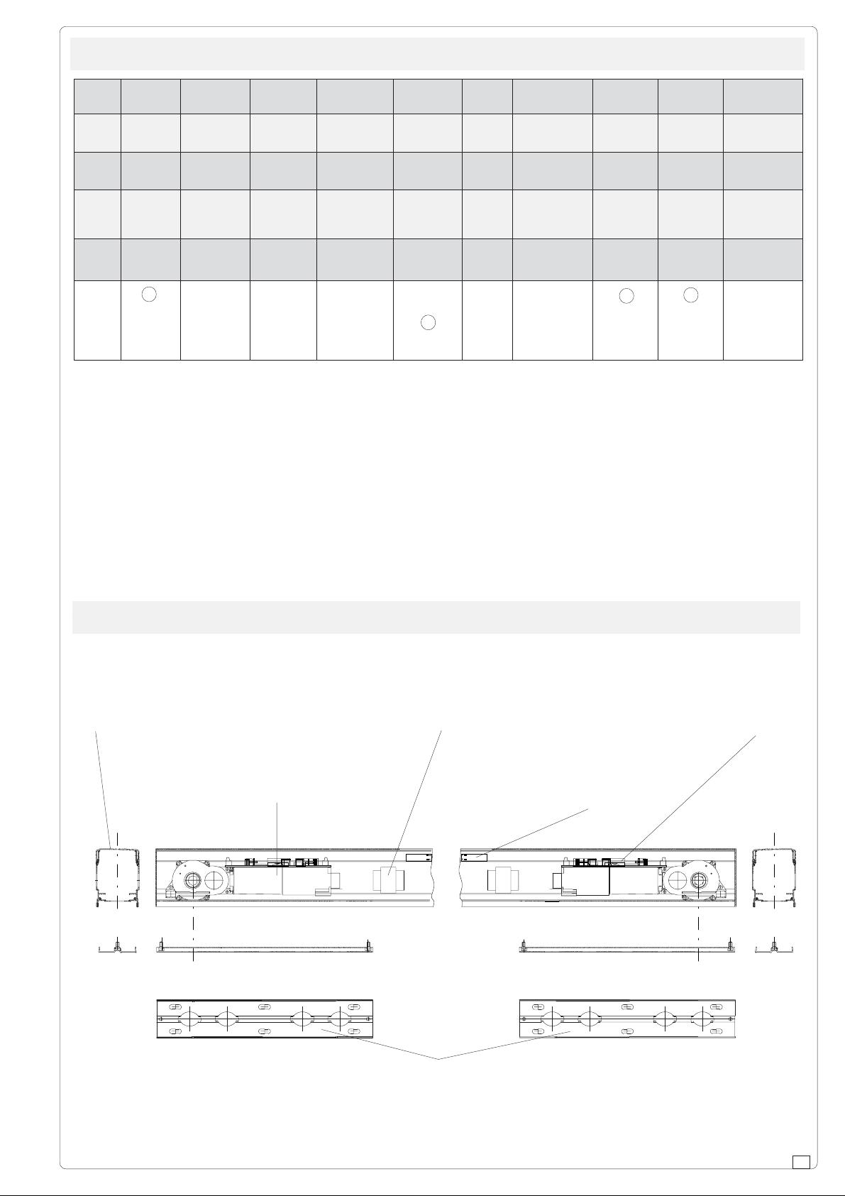
DESCRIZIONE DELLE PARTI /
BESCHREIBUNG DER BAUTEILE
Involucro
Enclosure
Boîtier
Gehäuse
Envoltura
Motoriduttore
Gearmotor
Motorreductor
Getriebemotor
Motoréducteur
Electric locking system included
DESCRIPTION OF COMPONENTS
/ DESCRIPCION DE LAS PARTES
Trasformatore
Transformer
Transformateur
Transforma
Motoréducteur
- Y compris serrure électrique -
/ DESCRIPTION DES PIECES
Batterie
Battery
Batteries
Batterien
Baterías
Einschließlich Elektroschloß
Scheda comando
Control panel
Armoire de commande
Schalttafel
Tarjeta de mando
Base di fissaggio
Anchoring base
Base de fixation
Basis zur Antringung
Base de sujeción
33
3
33
Page 4

8080
80
8080
DIMENSIONI E MISURE DI FISSAGGIO /
DE FIXATION /
ITALIANO
GRÖSSE UND ABMESSUNGEN FÜR DIE ANBRINGUNG
ANCHORING DIMENSIONS AND MEASUREMENTS
/ DIMENSIONES Y MEDIDAS DE SUJECIÓN
/ DIMENSIONS ET MESURES
La misura C (interasse cerniere) deve essere rilevata e comunicata per definire l'esecuzione
dell'automazione stessa (Rif. PF2100), inoltre è di rif erimento per il fissaggio delle basi di
ancoraggio.
Nelle esecuzioni Standard, le misure A (tra interasse cerniera e interasse braccio) sono pari a 100 mm e la misura T (lunghezza trav e PF2100) corrisponde alla C.
Nei casi di involucro con lunghezza maggiore, deve essere comunicata la misura T in quanto è diversa dalla C e le misure (A
C = T Standar
sx) e (A dx) di disassamento se non sono simmetriche.
ENGLISH
Measurement of C (hinge axle base) must be
taken and notified to define the execution of the
automation itself (Ref. PF2100); it is also useful as
reference for securing the anchoring bases.
In the Standard execution, the A measurements
(between hinge axle base and arm axle base)
equal 100 mm and the measurement for T (PF2100
beam length) corresponds to C.
If the enclosure is longer, the T measurement
must be taken as it varies from the C measurement and the misalignment (A left and A right)
measurements if they are not symmetrical.
FRANÇAIS
LUNGHEZZA MINIMA INVOLUCRO = 1,160 m
LUNGHEZZA MASSIMA INVOLUCRO = 5,000 m
MINIMUM LENGTH OF ENCLOSURE = 1,160m
MAXIMUM LENGTH OF ENCLOSURE = 5,000m
LONGUEUR MINIMUM BOÎTIER = 1,160m
LONGUEUR MAXIMUM BOÎTIER = 5,000m
MINDESTLÄNGE GEHÄUSE = 1,160m
HÖCHSTLÄNGE GEHÄUSE = 5,000m
LONGITUD MÍNIMA ENVOLTURA = 1,160m
LONGITUD MÁXIMA ENVOLTURA = 5,000m
Relever et communiquer la mesure C (distance
charnières) pour définir la version de l’automation
T = C
(Réf. PF2100), celle-ci sert également de référence
pour fixer les bases d’ancrage.
Dans les versions standard, les mesures A (entre
distance charnières et distance bras) sont égales
à 100 mm et la mesure T (longueur poutre PF2100)
correspond à la mesure C.
Si le boîtier a une longueur supérieure,
communiquer la mesure T car elle est différente
de la mesure C ainsi que les mesures (A gauche)
et (A droite) de désaxement si elles ne sont pas
symétriques
DEUTSCH
Der Wert C (Abstand Scharniere) muß gemessen und mitgeteilt werden, da er für die Ausführung vom Automatikantrieb
benötigt wird (Rif. PF2100). Außerdem dient er als Bezug für die Anbringung der Verankerungsbasis.
Bei den Standardausführungen entsprechen die Werte A (Abstand Scharnier und Abstand Arm) 100 mm und der Wert
T (Länge vom Querträger PF2100) dem Wert C.
Bei längeren Gehäusen muß der Wert T mitgeteilt werden, da er vom Wert C abweicht, sowie die Werte (A links) und
(A rechts) der Fluchtabweichung, falls sie nicht symmetrisch sind.
100
114
ESPANOL
Hay que medir y comunicar la medida
155
71
C (distancia entre ejes de las
bisagras), que sirve para definir la
ejecución de la misma automatización
(Ref. PF2100), y como referencia para
la fijación de las bases de anclaje.
En las ejecuciones Estándares, las
medidas A (distancia entre el eje de la
bisagra y el eje del brazo) son iguales
a 100 mm y la medida T (longitud
perfil PF2100) corresponde a la C.
En los casos de envoltura más larga,
hay que comunicar la medida T puesto
que es diferente de la C y las medidas
(A izq) y (A der.) de desalineación si
no son simétricas
49.5 237
44
4
44
96
237
11
37
30
45
200 8787 99.5 99.5
573
49.5
65
100
Page 5

DEFINIZIONI DI POSIZIONAMENTO /
POSITIONING
HINWEISE ZUR POSITIONIERUNG /
ITALIANO
1) L'automazione è già programmata in funzionamento
MASTER-SLAVE. Le schede comando sono contrassegnate con etichette visibili.
2) Posizionare il lato MASTER sull'anta che deve chiudere per 2a.
3) L'automazione ha uscite simmetriche per l'attacco dei
bracci (PB1001-1002). Nel caso si necessiti, invertire la
posizione MASTER-SLAVE, rovesciare la trave PB2100
come da figura.
ENGLISH
/ DEFINITIONS DU POSITIONNEMENT
DEFINICIONES DE POSICIONAMIENTO
11
1
11
N
21345678910O
SLAVE
MASTER
21 345678910O
N
1) Automation is already programmed in the MASTERSLAVE mode. The control boards are marked with distinct
labels.
2) Place the MASTER side on the door that must close
last.
3) The automation has symmetrical outlets for mounting
the arms (PB1001-1002). If necessary, invert the position
of the MASTER-SLAVE and turn over the PB2100 beam
as illustrated in the figure.
FRANÇAIS
1)L’automation est déjà programmée pour le
fonctionnement MASTER-SLAVE (maître/ auxiliaire). Les
cartes de commande sont indiquées par des étiquettes
visibles.
2) Placer le côté MASTER sur le battant qui doit fermer en
second.
3) L’automation a des sorties symétriques pour le raccord
des bras (PB1001-1002). En cas de besoin, inverser la
position MASTER-SLAVE, renverser la poutre PB2100
comme indiqué sur la figure.
DEUTSCH
1) Die Automatik ist bereits in der MASTER-SLAVE
Funktionsweise programmiert. Die Steuerkarten sind mit
sichtbaren Aufklebern gekennzeichnet.
2) Die MASTER-Seite an dem Türflügel positionieren, der
als zweiter geschlossen wird.
3)Die Automatik hat symmetrische Ausgänge zur
Anbringung der Arme (PB1001-1002). Falls nötig, die
MASTER-SLAVE Position vertauschen und den
Querträger PB2100 so umdrehen, wie auf der Abbildung
zu sehen ist.
SLAVE MASTER
((
(chiusura anticipata)
((
(closure brought forward)
(fermeture anticipée)
(Vorgezogenes Schließen)
(cierre anticipado)
M
A
S
T
E
R
22
2
22
(chiusura ritardata)
(closure-delayed)
(fermeture retardée)
(Verzögertes Schließen)
(cierre retardado)
33
3
33
MASTERSLAVE
M
A
S
T
E
R
ESPANOL
1) La automatización ya está programada en funcionamiento MASTER-SLAVE. Las tarjetas de mando están
marcadas con etiquetas visibles.
2) Coloque el lado MASTER en la puerta que se ha de
cerrar en segundo lugar.
3) La automatización tiene salidas simétricas para la
conexión de los brazos (PB1001-1002). Si se requiere la
inversión de la posición MASTER-SLAVE, invierta el perfil
PB2100 como muestra la figura.
SLAVEMASTER
55
5
55
Page 6

ISTRUZIONI DI MONTAGGIO /
MONTAGEANLEITUNG
ITALIANO
ASSEMBLY INSTRUCTIONS
/ INSTRUCCIONES DE MONTAJE
1) Togliere il coperchio dall'involucro con l'aiuto di un cac-
ciavite a taglio.
2) Allentare le viti delle basi fissaggio dei trasformatori (cacciavite a croce) e solo se necessario spostare i trasformatori in modo da liberare i dadi M8 (chiave a tubo da 13).
Togliere le basi di fissaggio dall'involucro motore.
3) Allineare le basi alle ante, seguendo i riferimenti orizzontali indicati nel disegno (per quelli verticali seguire le
misure applicative specifiche al braccio di azionamento da
utilizzare, PB1001 pag.8÷9, PB1002 pag.10÷12).
Fissare adeguatamente le basi su più punti facendo fuoriuscire le viti M8 come indicato nel disegno. Attenzione: predisporre i cavi cablaggio (vedi ingresso cavi).
4) Dopo il fissaggio delle basi, allineare i fori dell'involucro
motore alle viti M8 delle basi, far passare i cavi cab laggio e
fissare le due parti con gli scontri e i dadi in dotazione (chiave
a tubo da 13)
5) Riposizionare, bloccare e ricollegare i trasformatori (cacciavite a croce).
Eseguire i collegamenti elettrici nei due quadri, seguendo
le istruzioni del paragrafo relativo (pag.16÷17).
/ INSTRUCTIONS POUR LE MONTAGE
11
1
11
ENGLISH
1) Remove the cover from the enclosure with a screwdriver.
2) Loosen the screws from the transformer anchoring base
(Phillips screwdriver) and move the transformers to loosen
the M8 nuts (13-socket spanner) only if necessary.
Remove the anchoring bases from the motor’s enclosure.
3) Align the bases to the doors according to the horizontal
reference marks indicated in the drawing (for the vertical
ones, follow the application measurements specific to the
operating arm to be used, PB1001 pg.8-9, PB1002 pg.10-
12).
Adequately secure the bases at various points, making the
M8 screws emerge as indicated in the drawing. Warning:
prepare the cables beforehand (see cable inlet).
4) After fixing the bases, align the motor enclosure’s screw
holes to the bases’ M8 screws, feeding the cables through
and fixing the two parts with the pawls and the nuts provided
(13-socket spanner)
5) Replace, secure and reconnect the transformers (Philips
screwdriver).
Follow instructions found in the appropriate paragraph (pg.16-
17) to make the necessary electrical connections in the two
boards.
22
2
22
UNI 5739 M8x20
33
3
33
FRANÇAIS
1) Enlever le couvercle du boîtier à l’aide d’un tournevis plat.
2) Desserrer les vis des bases de fixation des transformateurs
(tournevis cruciforme) et ne déplacer les transformateurs
afin de libérer les écrous M8 (clé à tube de 13) que si c’est
nécessaire.
Enlever les bases de fixation du boîtier moteur.
3) Aligner les bases aux battants en suivant les références
horizontales indiquées dans le dessin (pour les références
66
6
66
I
NGRESSO CAVI
C
ABLE INLET
E
NTRÉE DES CÂBLES
K
ABELEINGANG
E
NTRADA CABLES
Page 7

verticales, suivre les mesures spécifiques d’application au
I
NGRESSO CAVI
C
ABLE INLET
E
NTRÉE DE S CÂBLES
K
ABELEINGANG
E
NTRADA CABLES
bras d’actionnement à utiliser, PB1001 pages 8÷9, PB1002
pages 10÷12).
Fixer correctement les bases en plusieurs endroits en faisant
sortir les vis M8 comme indiqué sur le dessin. Attention:
prévoir les câbles de branchement (voir entrée câbles).
4) Après avoir fixé les bases, aligner les trous du boîtier
moteur aux vis M8 des bases, faire passer les câbles de
branchement et fixer les deux parties avec les vis et les
écrous fournis de série (clé à tube de 13)
5) Replacer, bloquer et brancher à nouveau les
transformateurs (tournevis cruciforme).
Effectuer les branchements électriques dans les deux tableaux
en suivant les instructions du paragraphe correspondant
(pages 16÷17).
DEUTSCH
1) Mithilfe eines Schraubenziehers den Deckel vom Gehäuse
entfernen.
2) Die Schrauben der Basis, an der die Trafos befestigt sind,
lösen (Kreuzschlitzschraubenzieher). Die Trafos nur dann
verschieben, wenn dies nötig ist, um Zugriff auf die M8Muttern zu haben (13-er Steckschlüssel).
Die Befestigungsbasen vom Motorgehäuse abmachen.
3) Die Basen mit den Türflügeln ausrichten und dabei die
horizontalen Bezüge beachten, die in der Zeichnung
angegeben sind (für die vertikalen Bezüge siehe
entsprechende Werte vom jeweils verwendeten Antriebsarm:
PB1001 S. 8-9 und PB1002 S. 10-12).
Die Basen an den entsprechenden Punkten befestigen.
Dabei müssen die M8 Schrauben herauskommen, wie auf
der Abbildung zu sehen ist. Achtung: Die Kabel bereitstellen
(siehe Kabeleingang)!
4) Nachdem die Basen befestigt worden sind, die Löcher
vom Motorgehäuse mit den M8-Schrauben der Basen
ausrichten, das Kabel durchziehen und die beiden Teile mit
den beiliegenden Gegenstücken und Muttern befestigen
(13-er Steckschlüssel).
5) Die Trafos wieder in ihre ursprüngliche Position bringen,
blockieren und anschließen (Kreuzschlitzschraubenzieher).
Die Stromanschlüsse an den beiden Schalttafeln nach den
Anweisungen im entsprechenden Abschnitt (S. 16÷17)
durchführen.
44
4
44
55
5
55
ESPANOL
1) Quite la tapa de la envoltura ayudándose con un destornillador.
2) Afloje los tornillos de las bases de fijación de los transformadores (destornillador cruciforme) y, sólo si fuera
necesario, corra los transformadores para poder quitar las tuercas M8 (llave de tubo de 13).
Quite las base de fijación de la envoltura del motor.
3) Alinee las bases a las hojas, siguiendo las referencias horizontales indicadas en el dibujo (para las verticales siga
las medidas específicas de aplicación del brazo de accionamiento que se ha de usar, PB1001 págs.8˜9, PB1002
págs.10˜12).
Fije de manera adecuada las bases sobre varios puntos haciendo salir los tornillos M8 como indicado en el dibujo.
Atención: prepare los cables para el cableado (véase entrada cables).
4) Tras fijar las bases, alinee los agujeros de la envoltura del motor con los tornillos M8 de las bases, haga pasar los
cables y fije las dos piezas con los casquillos roscados y tuercas suministrados (llave de tubo de 13)
5) Vuelva a posicionar, bloquee y conecte de nuevo los transformadores (destornillador cruciforme).
Haga las conexiones eléctricas en los dos cuadros, siguiendo las instrucciones del párrafo respectivo
(págs.16÷17).
77
7
77
Page 8

PB1001 - BRACCIO A SLITTA /
Assi & ingombri /
dimensione / peso
dimensions / weights
dimensions / poids
Abmessungen / Gewicht
dimensiones / pesos
0.80 m - 250 kg
1.00 m - 200 kg
1.20 m - 150 kg
Centre lines and external dimensions
PB1001 - GLEIT ARM
PB1001 - SLIDING ARM
/ Axes et encombrements /
/ PB1001 - BRAZO DESLIZANTE
/ PB1001 - BRAS À GLISSIÈRE
Achsen & Abmessungen
/ Ejes y dimensiones máximas
L'angolo di apertura standar è
regolabile fino a
100°÷120° (vedi
tabella).
Attenzione: nella
massima apertura
sono indispensabili
i fermi a pavimento
per ovviare che
l'oltrecorsa danneggi bracci e
motori.
ß
A
B
D
ß
The standard
opening angle can
be adjusted up to
100°÷120° (see
table).
Warning: at
maximum aperture,
ground anchors are
necessary to keep
the overstop from
damaging the arms
and motors.
°001 °021
001 001
56 56
083 533
L'angle d'ouverture
standard est
réglable jusqu'à
100÷120° (voir
tableau).
Attention: les arrêts
au sol sont
indispensables en
ouverture maximum
pour éviter que le
mouvement horscourse n'abîme les
bras et les moteurs.
D
B
A
ß
Der Standardöffnungswinkel kann
bis zu 100° bis 120°
eingestellt werden
(siehe Tabelle).
Achtung: Bei
maximaler Öffnung
sind Türstopper auf
dem Boden nötig,
damit die Arme und
Motoren nicht durch
zu weites Öffnen
beschädigt werden.
El ángulo de apertura estándar se
regula hasta
100°÷120° (véase
tabla).
Atención: es
indispensable
colocar topes en el
piso para la apertura máxima y así
evitar que la
superación de la
carrera máxima
averíe los brazos y
motores.
88
8
88
Page 9

139
102
5
Applicazione standard
Standar application
Application standard
Standardanbringung
Aplicación estándar
400
114
112
Applicazione disassata
Misaligned application
Application désaxée
155
71
75
5
Anbringung mit Fluchtabweichung
Aplicación desalineada
Scontro di fissaggio
Fixing ward
Butee de fixation
Gegenstück
Controplaca de fijación
Con spessoramento abbassato vite M6x35
M6x35 screws for lowered shimming
Avec cale abaissée vis M6x35
Mit verkürztem Distanzstück Schraube M6x35
Con arandela distanciadora baja tornillo M6x35
Il punto di fissaggio del motoriduttore, deve rispettare gli allineamenti definiti.
The gear motor's anchorage point must match
the established alignments.
Le point de fixation du motoréducteur doit
respecter les alignements définis.
Der Punkt, an dem der Getriebemotor
angebracht wird, muß mit den vorgegebenen
Ausrichtungen übereinstimmen.
El punto de sujeción del motorreductor tiene que
respetar las alineaciones definidas.
D
Con spessoramento lungo vite M6x60
M6x60 screws for long shimming
Avec cale longue vis M6x60
Mit langem Distanzstück Schraube M6x60
Con arandela distanciadora alta tornillo M6x60
Nei casi necessiti maggiore
*
disassamento tra slitta e
bracci, usufruire apposita
boccola e vite M6x35 di serie
(B).
18
15±0,2
6,5
B
In case more misalignment is
*
necessary between runner and
arms, use appropriate bush and
M6x35 (B) series screws.
S'il faut davantage de
*
désaxement entre la glissiére
et les bras, utiliser une douille
prévue à cet effet et les vis
M6x35 de série (B).
*
Wenn eine größere
Fluchtabweichung zwischen
Schlitten und Armen nötig ist,
die entsprechende Buchse und
die serienmäßigen Schrauben
M6x35 (B) verwenden.
Cuando se requiera una mayor
*
desalineación entre corredera
y brazos, aproveche el
casquillo y tornillos M6x35
suministrado de serie (B).
SNODO -
GELENK
B
Foro di riferimento asse braccio
Reference hole for arm axle
Trou de référence axe bras
Bezugsbohrung Achse Arm
Agujero de referencia eje del brazo
A
max. 30 mm a filo superiore anta
30 mm max. distance from the uppe r edge of the door
max 30 mm, à fil du côté supérieur du vantail
max. 30 mm von der oberen Türkante entfernt
máx. 30 mm a filo superior puerta
280
*
*
*
*
*
Scontro acciaio
Steel pawl
Butée acier
Stahlgegenstück
Casquillo roscado de acero
ARTICULATION
ARTICULATION
- ARTICULACIÓN
Vite M6x16
M6x16 screw
Vis M6x16
Schraube M6x16
Tornillo M6x16
Boccola ottone
Brass bush
Douille laiton
Messingbuchse
Casquillo de
latón
99
9
99
Page 10

PB1002 - BRACCIO SNOD A T O /
°021<ß
001=A
024<B
053<C
052=D
°081<ß
001=A
021<B
05<C
052=D
PB1002 - GELENKARM
Assi & ingombri / Assi & ingombri /
Assi & ingombri / Centre lines and external dimensions
Assi & ingombri / Assi & ingombri /
dimensione / peso
dimensions / weights
dimensions / poids
Abmessungen / Gewicht
dimensiones / pesos
0.80 m - 250 kg
1.00 m - 200 kg
1.20 m - 150 kg
ARTICULATED ARM - PB1002
/ PB1002 - BRAS ARTICULÉ
/ PB1002 - BRAZO ARTICULADO
/ Axes et encombrements / / Axes et encombrements /
/ Axes et encombrements / Achsen & Abmessungen
/ Axes et encombrements / / Axes et encombrements /
/ Ejes y dimensiones máximas/ Ejes y dimensiones máximas
/ Ejes y dimensiones máximas
/ Ejes y dimensiones máximas/ Ejes y dimensiones máximas
D=250
ß
C=350 max
B=420 ma x
71
A=100
120
ß
ß ß
ß = min 15° - max 120°
ß ß
180
D=250
ß
50
71
B<120
ß
120
D=250
ß
C=350 max
B=420 ma x
A=100
71
D=250
ß
180
ß
71 50
B<120
ß
1010
10
1010
A=100
A=100
Page 11

Il sistema garantisce
sempre una apertura dell'anta a 120°,
tuttavia può anche
arrivare a 180°, a
condizione che "B"
sia limitata.
Le misure "A" e "D"
sono fisse. Compensare le differenti
misure di "B"
variando la lunghezza della leva di
rinvio come da fig.a.
Fare attenzione che
alla massima apertura anta, l'angolo
tra braccio e leva di
rinvio "ß" non
superi i 120° e in
chiusura non sia
inferiore a 15°.
Nota: Nelle applicazioni con massima
estensione della
leva di rinvio limitare la portata massima del 30%.
Nel punto di massima apertura sono
indispensabili i
fermi a pavimento
per ovviare che
l'oltrecorsa danneggi bracci e motori.
This system is
designed to open
swinging door wings to
a 120° angle. However,
a 180° opening angle
is possible as long as
distance "B" is not
excessive. Distances
"A" and "D" cannot be
changed. To compensate for differences in
distance "B", change
the length of the idle
arm as shown on the
figure. Howeve r, be
sure that the angle
between the
transmission arm and
idle arm "ß" does not
exceed 120° when the
door wing is opened all
the way, and 15° when
the door wing is
closed.
Note: The maximum
load capacity of the
system is reduced by
30% when the idle arm
is fully extended.
A maximum aperture,
ground anchors are
necessary to keep the
overstop from
damaging the arms
and motors.
Le systéme garantit
toujours une ouverture du vantail à 120°,
cependant l'ouverture peut arriver
jusqu'à 180° à
condition que la
dimension"B" soit
limitée. Les
dimensions "A" et
"D" sont fixes.
Compenser les
différentes dimensions "B" en
modifiant la longueur
du levier de renvoi
comme en fig.a.
Veiller à ce que,
quand l'ouverture du
vantail est à son
maximum, l'angle "ß"
entre le bras et le
levier de renv oi ne
dépasse pas 120° et à
ce que cet angle ne
soit pas inférieur à
15° en fermeture.
Remarque: Dans les
applications avec
extension maximale
du levier de renvoi,
limiter de 30% la
portée maximale.
Les arrêts au sol
sont indispensables
en ouverture
maximum pour éviter
que le mouvement
hors-course n'abîme
les bras et les
moteurs.
Das Antriebssystem
gewährleistet einen
Türöffnungs wink el v on
120°, der bei
Reduzierung des
Maßes "B" können
durch Längenänderung
des Vorgelegehebels
ausgeglichen werden
(siehe Abb.a).
Achtung: der zwischen
Arm und
Vorgelegehebel
liegende Winkel "ß"
darf bei maximaler
T ürflügeloffn ung 120°
nicht überschreiten
und muß bei
geschlossener T ür
mindestens 15°
betragen.
Hinweis: bei maximaler
Extension des Vorgelegehebels ist die
Höchstbelastungsfähigkeit um
30% zu reduzieren.
An der Stelle der
maximalen T üröffnung
müssen Türstopper am
Boden angebracht
werden, damit Arme
und Motoren nicht
durch zu weites Öffnen
beschädigt werden.
fig.a
El sistema garantiza
siempre una apertura de la puerta a
120°, sivembar go
puede llegar incluso
a 180°, con la
condición de que
"B" sea limitada.
Las medidas "A" y
"D" son fijas. Compensar las
diferentes medidas
de "B" variando la
longitud de la
palanca de reenvio
como indica la fig.a.
Prestar atención a
que, con la puerta
en apertura máxima,
el ángulo entre el
brazo y la planca de
reenvio "ß" no
supere los 120° y en
fase de cierre no
sea inferior a 15°.
Nota: En las aplicaciones con máxima
extensión de la
palanca de reenvio
limitar el alcance
máximo del 30%.
Es indispensable
colocar topes en el
piso para la apertura
máxima y así evitar
que la superación
de la carrera
máxima averíe los
brazos y motores.
Foro di riferimento asse braccio
Reference hole for arm axle
Trou de référence axe bras
Bezugsbohrung Achse Arm
Agujero de referencia eje del brazo
80
C
B
100
A=100
D=250
60
SNODO -
Vite M6x16
M6x16 screw
Vis M6x16
Schraube M6x16
Tornillo M6x16
ARTICULATION
GELENK
534 max.
329 min.
- ARTICULATION
- ARTICULACIÓN
71
min
ß
Scontro acciaio
Steel pawl
Butée acier
Stahlgegenstück
R
Casquillo roscado
de acero
Boccola ottone
Brass bush
Douille laiton
Messingbuchse
Casquillo de latón
1111
11
1111
Page 12

Applicazione su porte superiori a 2.5 m.
Installation on doors with height exceeding 2.5 m.
Application sur portes de plus de 2.5 m.
Anbringung bei über 2.5 m hohen T üren.
Aplicación en puertas superiores a 2.5 m.
155
71
80
min. 90
147
Applicazione su porte inferiori a 2.5 m.
Installation on doors with height less than 2.5 m.
Application sur portes de moins de 2.5 m.
Anbringung bei unter 2.5 m hohen T üren.
Aplicación en puertas inferiores a 2.5 m.
114
80
min. 110
133
min. 10
Con spessoramento abbassato vite M6x35
M6x35 screws for lowered shimming
Avec cale abaissée vis M6x35
Mit verkürztem Distanzstück Schraube M6x35
Con arandela distanciadora baja tornillo M6x35
Il punto di fissaggio del
motoriduttore, fa
riferimento al
bordo inferiore
della luce di passaggio (Lp). Le leve
di trasmissione,
nell'azionamento
dell'anta, devono
passare sotto tale
ingombro. Rispettare le distanze
minime riportate
negli esempi
facendo attenzione
alle altezze del
vano. Nel caso di
altezze inferiori ai
2,5 metri, la luce
(Lp) non deve
essere inferiore ai
30 mm, vanno
perciò utilizzate la
boccola e la vite
maggiorate in
dotazione (M6x60
UNI 5933).
The mounting point
for the gear motor is
determined in
reference to top edge
of the passageway
(Lp). During
operation, the
transmission levers
must pass below the
top edge of the
passageway. Be sure
to respect the
minimum distances
indicated on the
examples. Also, pay
special attention to
the height of the
door: if the door is
less than 2.5 metres
tall, the gap (Lp)
between upper edge
of the door and the
arm must be at least
30 mm (see figure).
In this case, use the
bushing and
oversized screw (M6
x 60, UNI5933)
supplied with the unit.
1212
12
1212
L p
Scontro di fissaggio
Fixing ward
Butee de fixation
Gegenstück
Controplaca de fijación
Le point de fixation
du motoréducteur
se réfère au board
inférieur de l'espace
de passage (Lp).
Quand le vantail est
actionné, les leviers
de transmission
doivent passer sous
cet encombrement.
Respecter les
distances
minimales
reportées dans les
exemples en faisant
attention aux
hauteurs de
l'espace. En cas
d'hauteurs
inférieures à 2,5 m,
le passage (Lp) ne
doit pas être
inférieur à 30 mm, il
faut donc utiliser la
bague et la vis
majorées fournies
avec le matériel (M6
x 60 UNI5933).
min. 30
Con spessoramento lungo vite M6x60
M6x60 screws for long shimming
Avec cale longue vis M6x60
Mit langem Distanzstück Schraube M6x60
Con arandela distanciadora alta tornillo M6x60
Als Bezugspunkt für
die Montage des
Getriebemotors dient
der untere Rand der
lichten
Durchgangshöhe
(Lp). Die
Antriebshebel
müssen während der
Türbewegung bzw.
des Türantriebs
ungehindert darunter
passieren können.
Die in den
Montagebeispielen
angegebenen
Mindestabstände und
die Höhe der
Türöffnung sind
unbedingt
einzuhalten bzw. zu
beachten. Bei unter
2,5 m liegender
Türhöhe muß der
lichte (Lp) Abstand
Mindestens 30 mm
betragen und es sind
daher die zum
Lieferumfang
El punto de fijación
del motorreductor
toma como
referencia el borde
inferior de la luz de
paso (Lp). Las
palancas de
transmisión, en el
accionamiento de
la puerta, deben
pasar por debajo
de dicha zona.
Respetar las
distancias mínimas
indicadas en los
ejemplos prestando atención a las
alturas del vano.
En el caso de
alturas inferiores a
2,5 m, la luz (Lp)
no debe ser
inferior a 30 mm,
por lo tanto es
preciso utilizar el
casquillo y el
tornillo
sobredimensionados
(M6x60 UNI5933).
gehörende
überdimensionierte
Buchse und die
überdimensionierte
Schraube (M6 x 60
UNI5933) zu
L p
Page 13

QUADRO COMANDO ZP10 /
12345678910
MF9011 - MF9111
MA7034
+
-
+
-
+
-
+
-
12
ZP10
CAME
SCHALTAFFEL ZP10
24V + E1 E2 -
CONTROL PANEL ZP10
/ CUADRO DE MANDO ZP10
3
/ ARMOIRE DE COMMANDE ZP10
19
1
24V
4
24V
230V
230V
20
Connettori ad innesto /
Steckverbinder /
MA7034 = scheda sistema antipanico
MA7034 = card anti-panic system
MA7034 = carte sisteme antipanique
MA7034 = Brücken-Steckmodul antipanik-system
MA7034 = tarjeta sistema antipánico
MF9011/9111 = scheda micro-fotocellula di sicurezza
MF9011/9111 = card security micro-photocell
MF9011/9111 = carte micro-photocellule de securite
MF9011/9111 = Brücken-Steckmodul Sicherheitsfotozellen-
mikroschalter
MF9011/9111 = tarjeta micro-fotocelula de seguridad
2
Plug-in connectors /
Conectores a encastre
18
5
Connecteurs
6
14
9
8
7
10
PRINCIPALI COMPONENTI
1 Morsettiera per collegamento batterie
2 Morsettiere per collegamenti
3 Innesto per scheda MA7034
4 Fusibile accessori 2A
5 Innesto per scheda MF9011/9111
6 Fusibile centralina 630mA
7 Pulsanti di programmazione
8 LED di codifica/conteggio TCA
9 Pulsante RESET
10 Dip-switch "selezione funzioni" a 10 vie
11 Trimmer VEL regolazione velocità di marcia
12 Trimmer RALL regolazione velocità di rallentamento
13 Trimmer TCA regolazione chiusura automatica
14 Trimmer regolazione forza motore
15 Morsettiera per collegamento al motore
16 Morsettiera per collegamento tra 2 motori abbinati
17 Morsettiera per selettore funzioni
18 Dip-switch "selezione funzioni" a 2 vie
19 Fusibile motore 5A
20 Fusibile linea 5A
11
12 13
15
16
17
II
I
II
MAIN COMPONENTS
1 Terminal boards for connection battery
2 Terminal boards for performing connections
3 Socket connecting card MA7034
4 Fuse on accessory power line, 2A
5 Socket connecting card MF9011/9111
6 Fuse on electronic control unit 630mA
7 Programming buttons
8 LED for coding/displaying the automatic closing time
9 RESET button
10 "Function selection" dip switch
11 Trimmer VEL adjustment of operating speed
12 Trimmer RALL adjustment of slowdown speed
13 Trimmer TCA regolazione automatic closing
14 Trimmer adjustment motor torque limiter
15 Terminal board for motor
16 Terminal board for connecting the two paired motors
17 Terminal board for function selector
18 "Function selection" dip switch
19 Fuse on motor, 5A
20 Fuse line 5A
HAUPTKOMPONENTEN
1 Anschlußklemmenbrett für Batterien
2 Anschlußklemmenbrett
3 Steckanschluß für Steckmodul MA7034
4 Zubehörsicherung 2A
5 Steckanschluß für Steckmodul MF9011/9111
6 Schaltkasten-Sicherung 630mA
7 Programmiertasten
8 LED Codierung/TCA-Zählung
9 RESET-Taste
10 Dip-switch "Funktionswahl"
11 Trimmer VEL einstellung Laufgeschwindigkeit
12 Trimmer RALL einstellung Laufverlangsamung
13 Trimmer TCA einstellung Schließautomatik
14 Trimmer einstellung Drehmomentbegrenzer des motors
15 Anschlußklemmenbrett für Motor
16 Klemmleiste für den Anschluß von 2 gekoppelten Motoren
17 Anschlußklemmenbrett für Functionswahlschalter
18 Dip-switch "Funktionswahl"
19 Motor-Sicherung 5A
20 Hauptsicherungen 5A
GBGB
GB
GBGB
DD
D
DD
PRINCIPAUX COMPOSANTS
1 Plaque à bornes pour branchement batteries
2 Plaque à bornes pour les branchements
3 Branchement pour carte MA7034
4 Fusible accessoires 2A
5 Branchement pour carte MF9011/9111
6 Fusible boîtier 630mA
7 Boutons-poussoirs de programmation
8 LED de codage/comptage TCA
9 Bouton-poussoir RESET
10 Dip-switch "sélection fonctions"
11 Trimmer VEL réglage vitesse de mouvement
12 Trimmer RALL réglage pendant le ralentissement
13 Trimmer TCA réglage fermeture automatique
14 Trimmer réglage limiteur de couple moteur
15 Plaque à borne pour moteur
16 Plaque à bornes pour bran. entre 2 moteurs accouplés
17 Plaque à bornes pour sélecteur de function
18 Dip-switch "sélection fonctions"
19 Fusible moteur 5A
20 Fusible de ligne 5A
COMPONENTES PRINCIPALES
1 Cajas de bornes para conexión baterias
2 Cajas de bornes para conexiones
3 Conexión para tarjeta MA7034
4 Fusible accesorios 2A
5 Conexión para tarjeta MF9011/9111
6 Fusible central 630mA
7 Teclas de programación
8 LED de codificación - cuenta TCA
9 Tecla RESET
10 Dip-switch "selección funciones"
11 Trimmer VELL regulación velocidad de marcha
12 Trimmer RALL regulación durante el ralentamiento
13 Trimmer TCA regulación cierre automático
14 Trimmer regulación limitador de par motor
15 Cajas de borne para conexión motor
16 Caja de bornes para conexión de 2 motores conjuntos
17 Cajas de bornes para selector funciones
18 Dip-switch "selección funciones"
19 Fusible motor 5A
20 Fusible línea 5A
FF
F
FF
EE
E
EE
1313
13
1313
Page 14

ITALIANO
DESCRIZIONE TECNICA SCHEDA BASE ZP10
L'automazione va alimentata con la
tensione di (230V a.c.) sui morsetti
dei trasformatori, (protetta in
ingresso con fusibili da 2A).
I comandi sono a bassa tensione e
sono protetti con fusibile accessori
da 2A. Le schede sono protette
con fusibili da 630 mA. La potenza
complessiva degli accessori a 24V
non deve superare i 30W (compresa elettroserratura).
Sicurezza
É sempre attivo un sistema di
verifica di ostacolo, che entra in
funzione instantaneamente quando
viene bloccato il moto dell'anta.
In apertura esegue la richiusura.
In chiusura esegue la riapertura.
Se l'ostacolo permane, esegue tre
tentate chiusure, fermandosi con
l'anta in appoggio all'ostacolo.
Dopo aver liberato l'anta, un
comando di apertura ne ripristina il
normale funzionamento.
Accessori di complemento
Dispositivi di sicurezza e di comando che possono essere inseriti
direttamente sulla scheda:
- MA7041 (selettore funzioni);
- MA7034 (sistema antipanico,
funzione solo tampone);
- MF9011/MF9111 (scheda microfotocellula di sicurezza).
Altre funzioni
Selezionabili tramite "dip-switch"
vedere a pag.17÷19).
- "Push & Go";
- "Wind Stop" di sicurezza;
- Rilevazione di presenza ostacolo;
- Comando "bistabile";
- Stop momentaneo;
- "Sistema antipanico".
Regolazioni
- Trimmer TCA = Il temporizzatore
di chiusura automatica si
autoalimenta a fine-tempo corsa in
apertura. Il tempo è comunque
subordinato dall'intervento di
eventuali accessori di sicurezza.
N.B: quando si alimenta il quadro,
la funzione di chiusura automatica
è subito attivata, indipendentemente dalla posizione dell'anta;
- Trimmer RALL = Velocità di
rallentamento;
- Trimmer VEL = Velocità di marcia
o tempo di apertura (vedi tabella
delle carat. tec. pag.3)
- Trimmer di regolazione coppia
motore.
Attenzione! Prima di intervenire all’interno dell’apparecchiatura, togliere la tensione di linea e
scollegare le batterie (se inserite).
ENGLISH
TECHNICAL DESCRIPTION ZP10 MOTHERBOARD
The automation is powered with
(230V a/c.) voltage on the transformers’ terminals, protected in input by a 2A fuse. The commands
are low voltage and are protected
by a 2A accessory fuse. 630 MA
fuses protect the boards. The 24V
accessories’ total voltage must not
go beyond 30W (including electric
locking device).
Safety
An obstacle check system is always turned on and is automatically activated when the door’s motion is blocked.
It reverses the door’s motion and
begins closing during the opening
phase.
It reverses the door’s motion and
begins opening during the closing
phase if the obstacle is not removed. It attempts closing three
times, after which the door stops at
the point where the obstacle is
present. After removing the obstacle, a command to open resumes
normal operation.
Accessories
Safety and command devices that
may be added directly to the boards:
- MA7041 (function selector);
- MA7034 (anti-panic system, only a
damper function);
- MF9011/MF9111 (card safety micro-photoelectric cell).
Other functions
These functions are selected on the
dip switches (see p.17÷19).
- “Push & Go”;
- “Wind Stop” safety feature;
- Detection of obstacle;
- "Step" command;
- Temporary stop;
- "Antipanic System";
Adjustments
- Trimmer TCA = The automatic
closing timer is automatically started
at the beginning of the slowdown
cycle during opening.This timer is
automatically interrupted when any
safety accessory is tripped,
regardless of the position of the
door wing;
- Trimmer RALL = Slowdown
speed: min/max;
- Trimmer VEL = Operating speed
or time required for opening the
gate (see table of the technical
characteristics pag.3);
- Trimmer adjustment motor torque
limiter.
Caution! Shut off the mains
power and disconnect the batteries
before servicing the inside of the
unit.
1414
14
1414
Page 15

FRANÇAIS
DESCRIPTION TECHNIQUE CARTE BASE ZP10
L’automation doit être alimentée avec
une tension de (230V c.a.) sur les
bornes des transformateurs et être
protégée à l’entrée par un fusible de
2A. Les commandes sont à basse
tension et sont protégées par un
fusible accessoires de 2A. Les cartes
sont protégées par des fusibles de
630 MA. La puissance totale des
accessoires à 24V ne doit pas
dépasser les 30W (y compris la
serrure électrique).
Sécurité
Un système de contrôle des
obstacles, qui se met à fonctionner
instantanément quand le mouvement
du battant est bloqué, est toujours
activé.
Il referme en ouverture.
Il rouvre en fermeture; si l’obstacle
subsiste, il effectue trois tentatives de
fermeture et le battant s’arrête
ensuite contre l’obstacle. Après avoir
libéré les battants, une commande
DEUTSCH
TECHNISCHE BESCHREIBUNG GRUNDPLATINE ZP10
Der Automatikantrieb wird mit einer
Spannung von 230 V WS gespeist,
die an den Klemmen der Trafos
angelegt wird und im Eingang mit
einer 2A Sicherung geschützt ist. Die
Steuerungen funktionieren mit
Niedrigspannung und sind durch 2A
Zusatzsicherungen geschützt. Die
Platinen sind durch 630 MA
Sicherungen geschützt. Die
Gesamtleistung der 24V Zubehörteile
darf 30W nicht übersteigen
(einschließlich Elektroschloß).
Sicherheit
Ein System zur Ermittlung eventueller
Hindernisse ist immer aktiviert und
schaltet sich sofort zu, wenn der
Motor vom Türflügel blockiert wird.
Beim Öffnen wird der Türflügel
wieder geschlossen.
Beim Schließen wird der Türflügel
wieder geöffnet. Wenn das Hindernis
weiterhin ermittelt wird, werden drei
Schließversuche durchgeführt.
Anschließend hält der Türflügel am
d’ouverture en rétablit le
fonctionnement normal.
Accessoires complémentaires
Dispositifs de sécurité et de
commande qui peuvent être branchés
directement sur les cartes:
- MA7041 (sélecteur fonctions);
- MA7034 (système anti-panique,
fonction uniquement tampon);
- MF9011/MF9111 (carte microphotocellule de sécurité).
Autres fonctions
Ces fonctions peuvent être
sélectionnées sur les dip (p.17÷19).
- "Push & Go";
- "Wind Stop" de sécurité;
- Détection de présence;
- Commande "bistable"
- Stop temporaire;
- "Système anti-panique".
Réglages
- Trimmer TCA = Temps de fermeture
Hindernis an. Nachdem das Hindernis
aus dem Weg geräumt wurde, kann
die normale Funktion durch einen
Befehl zum Öffnen wieder
aufgenommen werden.
Zusatzausstattung
Sicherheits- und Steuervorrichtungen,
die direkt auf die Karten gesteckt
werden können:
- MA7041 (Wählschalter für
Funktionen);
- MA7034 (Panikschutzsystem, nur als
Reserve bei Stromausfall gedacht);
- MF9011/MF9111 (BrückenSteckmodul MikroSicherheitsphotozelle).
Andere Wahlfunktionen
Diese Funktionene sind über "DipSwitch" wáhlbar (siehe Seite 17÷19).
- "Push & Go";
- "Wind Stop" - Sicherung;
- Hindernisaufnahme;
- Bistabiler Befehl"
- Momentaner Stop;
- "Panikschutzsystem".
automatique: da 1 a 16". Le temporisateur de fermeture automatique
s’autoalimente au début du temps de
ralentissement en ouverture. Le
temps est cependant subordonné à
l’intervention d’éventuels accessoires
de sécurité. N.B. : quand on alimente
l’armoire, la fonction de fermeture
automatique est immédiatement
activée, indépendamment de la
position du vantail;
- Trimmer RALL = Vitesse de ralentissement: min/max;
- Trimmer VEL = Vitesse de
mouvement ou temps d'ouverture
(voir tableau caracteristiques
techniques, pag.3);
- Trimmer réglage limiteur de couple
moteur min/max.
Attention! Avant d'intervenir à
l'intérieur de l'appareillage, couper
la tension de ligne et débrancher les
batteries (si branchées).
Einstellungen
- Trimmer TCA = Der
Schließautomatik-Zeitschalter speist
sich beim Öffnen am Beginn der
Laufverlangsamung selbst. Die voreingestellte Zeit ist auf jeden Fall
immer dem Eingriff eventuellen
Sicherheitszubehörs untergeordnet.
HINWEIS: wenn die Schalttafel mit
Strom versorgt wird, dann ist,
unabhängig von der Türflügelposition,
sofort auch die Schließ- automatikFunktion zugeschaltet;
- Trimmer RALL =
Laufverlangsamung: min/max;
- Trimmer VEL = Laufgeschwindigkeit
bzw. oder Öffnungszeit (sehen Tablle
Technische daten S.3);
- Trimmer einstellung Drehmomentbegrenzer des motors min/max.
Achtung! Das Gerät vor
Eingriffen im inneren spannungsfrei
schalten und die Stromzufuhr mittels
Batterien (falls zugeschaltet)
unterbrechen.
ESPAÑOL
DESCRIPCIÓN TÉCNICA TARJETA BASE ZP10
La automatización se alimenta con
tensión (230V c.a.) a los bornes de
los transformadores, protegida en
entrada con fusible de 2A. Los
mandos son de baja tensión y están
protegidos con fusibles auxiliares de
2A. Las tarjetas están protegidas con
fusibles de 630 mA. La potencia total
de los accesorios a 24V no tiene que
superar 30 W (incluida la
electrocerradura).
Seguridad
Un sistema de verificación de
obstáculo que se pone en
funcionamiento instantáneamente
cuando se bloquea el movimiento de
la hoja está siempre activo.
Durante la apertura se cierra.
Durante el cierre se abre, si el
obstáculo permanece, hace tres
tentativas, luego la hoja se detiene
apoyada contra el obstáculo. Tras
haber liberado las hojas, un mando
de apertura reactiva el
funcionamiento normal.
Accesorios complementarios
Dispositivos de seguridad y de
accionamiento que se pueden instalar
directamente en las tarjetas:
- MA7041 (selector funciones);
- MA7034 (sistema antipánico, función
sólo tampón);
- MF9011/MF9111 (Tarjeta microfotocélula de seguridad).
Regulaciones
Estas funciones se pueden seleccinar
por medio del "dip-switch" (ver
p.17÷19).
"Push & Go";
- "Wind Stop" de seguridad;
- Detección del obstáculo;
- Mando "biestable"
- Parada momentánea;
- "Sistema antipánico".
Regulaciones
- Trimmer TCA = El temporizador de
cierre automático se autoalimenta al
inicio del tiempo de ralentamiento en
apertura. En cualquier caso, el
tiempo está subordinado a la
intervención de los posibles
accesorios de seguridad. N.B:
cuando se alimenta el cuadro, la
función de cierre automático se
activa inmediatamente,
independientemente de la posición
de la puerta;
- Trimer RALL = Velocidad de
ralentamiento: min/max;
- Trimer VEL = Velocidad de marcha
o tiempo de apertura (mirar tabla
caracteristicas tecnicas pág.3);
- Trimer regulación limitador de para
motor.
Atención! Antes de actuar
dentro del aparado, quitar la
tensión de línea y desecnectar las
baterías (si estuvieran
conectadas).
1515
15
1515
Page 16

COLLEGAMENTI ELETTRICI /
Eseguire solo sulla morsettiera MASTER i collegamenti elettrici e le
selezioni predisposte
normalmente (es.: selettore MA7041, fotocellule
MF9011/9111, elettroserratura, attivazione
«comando bistabile»,
ecc.). Sulla SLAVE, assicurarsi che ci sia il ponte tra i morsetti 1-2.
DOC P
LBC
ENTRY EXIT
CLOS ED EMERGEN CY
SELECTION
1 2 3 4 5 6 7
ELECTRICAL CONNECTIONS
ELEKTRISCHE ANSCHLUSSE
Make electrical connections
only on the MASTER terminal board and the normally
preset selections (e.g.: the
MA7041 selector, MF9011/
9111 photoelectric cell, the
electric locking device, activating the “bistable command”, etc.). Make sure
there is a jumper between
1-2 terminals on the SLAVE
board.
230V
230V
24V
24V
La funzione di apertura parziale non
è abilitata anche se si selezioni dal
selettore MA7041.
The function for partial opening is not
enabled, even if it is selected on the
MA7041 selector.
La fonction d'ouverture partielle n'est
pas habilitée même si la sélection se
fait à partir du sélecteur MA7041.
Die Funktion für das teilweise Öffnen ist
nicht zugeschaltet, auch wenn sie vom
Wählschalter MA7041 aus angewählt
wird.
La función de apertura parcial no
está habilitada aunque se seleccione
mediante el selector MA7041.
N’effectuer les branchements électriques et les
sélections prévues
normalement (ex.:
sélecteur MA7041,
photocellule MF9011/9111,
serrure électrique,
activation “commande
bistable”, etc.) que sur la
plaque à bornes MASTER.
Contrôler s’il y a un
pontet entre les bornes 12 sur la plaque à bornes
SLAVE.
/ BRANCHEMENTS ELECTRIQUE
/ CONEXIONS ELECTRICAS
Die elektrischen Anschlüsse
und die normalerweise
vorgegebene Auswahl (z.B.
Wählschalter MA7041,
Sicherheitsphotozelle
MF9011/9111,
Elektroschloß, Aktivierung
vom “bistabilen Befehl”
usw.) dürfen nur am
Klemmbrett vom MASTER
ausgeführt werden. Am
Klemmbrett vom SLAVE
müssen die Klemmen 1 und
2 überbrückt werden.
Alimentazione dei quadri elettrici a 230V - 50/60 Hz
24V
24V
Terminal board for connecting motor power supply
Collegamento per alimentazione dei quadri elettrici
230V
Anschlußklemmenleiste für Motorstromversorgung
230V
Collegamento per alimentazione dei quadri elettrici
Nel caso non sia collegato il selettore MA7041 e si voglia comunque
ottenere la funzione antipanico, ponticellare i contatti 1-3 come
indicato in figura.
In case the MA7041 selector is not connected and you wish to activate the
antipanic function, bond contacts 1-3 as shown in the figure.
Si le sélecteur MA7041 n'est pas connecté et que l'on veuille quand
même obtenir la fonction anti-panique, mettre en pontet les contacts
1-3 comme il est indiqué sur la figure.
Falls der Wählschalter MA7041 nicht angeschlossen sein sollte und trotzdem die Panikschutzfunktion aktiviert werden soll, bitte die Kontakte 1 und
1 2 3 4 5 6 7
LBC
DOC P
3 wie auf der Abbildung dargestellt überbrücken.
Si no está conectado el selector
MA7041 pero se quiere obtener la función antipánico, conectar en derivación los contactos 1-3 como se indica
en la figura.
Haga sólo en el tablero
de bornes MASTER las
conexiones eléctricas y
las selecciones
preajustadas normalmente (ej.: selector
MA7041, fotocélula
MF9011/9111,
electrocerradura,
activación “mando
biestable”, etc.). En la
SLAVE, asegúrese de
que esté hecha la
conexión puente entre
los bornes 1-2.
M
N
+10
-11
2
R1
2
R2
2
R3
11
S
1616
16
1616
24V
+BATT-
+_E1 E2
10 11 S 1 2 R1 R2 R3 M C1 M N
1 2 3 4 5 6 7
TX RX GND
Motore - 24V (d.c.)
24V (d.c.) Motor
Moteur - 24V (c.c.)
M
Motor - 24V (Gleichstrom)
Motor - (d.c.)24V
Alimentazioni accessori 24V (a.c.) max. 15W
24V (a.c.)Powering accessories (max 15W)
Alimentation accessoires 24V (c.a.) max.15W
Zubehörspeisung 24V (Wechselstrom) max. 15W
Alimentación accesoios (a.c.) 24V max. 15W
Collegamento radar 1 di apertura (N.O.), viene escluso dal MA7041 in «EXIT»
Opening radar 1 (N.O.) connection; it is disabled from the MA7041 when in the «EXIT» position
Branchement radar 1 d'ouverture (N.O.), il est exclu par le sélecteur MA7041 en «EXIT»
Anschluß Radar 1 beim Öffnen (N.O.), wird vom MA7041 in «EXIT» ausgeschlossen
Conexión rádar 1 de apertura (N.O.), es desconectado por MA7041 en «EXIT»
Collegamento radar 2 di apertura (N.O.) o radar "stop momentaneo" (vedi dip 9, p.22÷24)
Opening radar 1 (N.O.) connection or "momentary stop" radar (see dip 9, pg. 22÷24)
Branchement radar 2 de ouverture (N.O.) ou radar "arrêt momentané" (voir dip 9, p.22÷24)
Anschluß Radar 2 beim Öffnen (N.O.) oder Radar "Vorübergehender Stop" (siehe dip 9, S.22÷24)
Conexión rádar 2 de apertura (N.O.) o radar "paro momentáneo" (véase dip 9, págs. 22÷24)
Il pulsante non interviene durante il movimento dell'anta. Se durante il conteggio della chiusura
automatica si preme il pulsante collegato su 2-R3, si ottiene la chiusura immediata della porta.
The button is not activated during the movement of the gate door. If the button connected to 2-R3 is pressed
during the automatic closure count, the door will close immediately.
Le bouton n'intervient pas durant le mouvement du battant. On obtient la fermeture immédiate de la
porte en appuyant sur le bouton branché sur 2-R3 durant le comptage de la fermeture automatique.
Der Druckknopf greift während des Türflügelbetriebs nicht ein. Wenn man den auf 2-R3 angeschlossenen
Druckknopf während der automatischen Schließung betätigt, wird die Tür sofort geschlossen.
El botón no interviene durante el movimiento de la hoja. Si durante la cuenta del cierre automático
se oprime el botón conectado a 2-R3, se obtiene el cierre inmediato de la puerta.
Collegamento elettroserratura 12V (a.c.) - ( 15W max.)
Connection for electrically-actuated 12V (a.c.) - (15W max.)
Connexion serrure èlectrique 12V (c.a.) - (15W max.)
Anschluß Elektroverriegelung 12V (Wechselstrom) -
(15W max.)
Conexión electrocerradura 12V (a.c.)- (15W max.)
Page 17

2
M
Manual button (N.O.)
Bouton-poussoir manuel (N.O.)
Taster Handbetrieb (N.O.)
Pulsador manual (N.O. )
Pulsante manuale (N.O.)
- Il contatto 2-M è normalmente aperto (N.O.) e ha una doppia funzionalità:
1) Nella situazione di normale funzionamento è abilitato all'apertura della sola automazione MASTER, anche se il
selettore funzioni MA7041 è selezionato in "porte chiuse". Questa funzione può essere utilizzata per passaggio
preferenziale, (es. chiusura serale, comando di apertura su selettori a chiave o magnetici).
2) Selezionando il dip 5 in ON si ha la funzione di apertura "bistabile" (premendo il pulsante l'anta apre, ripremendo
chiude). Attenzione, utilizzando questa funzione i contatti 2-R1 e 2-R2 vengono esclusi.
Nota: nel collegamento abbinato, il contatto è abilitato all'apertura della sola automazione MASTER.
- The 2-M contact is normally open (N.O.), and has a double function:
1) In an ordinary operating situation, it is activated only upon the opening of the MASTER automation, even if the MA7041
function selector is set to "closed doors". This function can be used for preferential passage, (e.g., evening closure, opening
command on key or magnetic switches).
2) By setting dip switch 5 to ON (10-way module), the “bistable” opening function is enabled (by pressing the button
the door opens; pressing it again closes the door). Attention, by using this function contacts 2-R1 and 2-R2 are excluded.
Note: in the combined connection the contact is set for the opening of the MASTER automation only.
- Le contact 2-M est normalement ouvert (N.O) est à une double fonctionnalité:
1) Durant le fonctionnement normal, il ne peut effectuer que l'ouverture de l'automation MASTER, même si le sélecteur des fonctions MA7041 est mis sur "portes fermée". Cette fonction peut être utilisée par passage préférentiel, (ex.
fermeture sérielle, commande d’ouverture sur des sélecteurs à clés ou magnétiques).
2) En sélectionnant le dip 5 sur ON (modules à 10 voies) on a la fonction d’ouverture “bistable” (en appuyant sur le
bouton la porte ouvre, en appuyant de nouveau elle ferme). Attention, en utilisant cette fonction les contacts 2-R1 et
2-R2 sont exclus.
Remarque: en cas de branchements accouplé, le contact n'est activé qu'à l'ouverture de l'automatisme principal
(MASTER).
Der Kontakt 2-M ist ein Normally-Open-Kontakt (NO) und hat eine doppelte Funktion:
1)Bei normalem Betrieb ist hiermit das Öffnen nur der MASTER-Automatik möglich, auch wenn der Wählschalter für Funktio
nen MA7041 auf "Türen geschlossen" steht. Diese Funktion kann für Durchfahrten mit Präferenz verwendet werden (z.B.
Schließen am Abend, Öffnungsbefehl mit Schlüssel oder Magnetschalter).
2)Wenn der Dip-Schalter 5 auf ON gestellt wird (10-Weg-Modul), wird die Funktion "bistabiler Befehl" aktiviert (bei
Drücken des Knopfes öffnet sich das Tor, bei erneutem Drücken schließt es sich wieder. Achtung! Wenn dieseFunktion aktiviert ist, werden die Kontakte 2-R1 und 2-R2 ausgeschlossen.
Anmerkung: beim kombinierten Anschluß, wird nur der Kontakt der MASTER-Automatik zum Öffnen befähigt.
- El contacto 2-M es del tipo normalmente abierto (N.O.) y desempeña dos funciones:
1) En situación de funcionamiento normal, está habilitada la apertura sólo de la automatización MASTER, si bien el
selector funciones MA7041 està colocado en "puertas cerradas". Esta función puede utilizarse para un pasaje de
preferencia (p. ej. cierre nocturno, mando de apertura en selectores de llave o magnéticos).
2) Situando el dip 5 en ON (módulo de 10 vías) se obtiene la función de apertura «paso a paso» (oprimiendo el pulsador la hoja se abre, al oprimirlo de nuevo se cierra). Atención, utilizando esta función los contactos 2-R1 y 2-R2 se
inhabilitan.
Nota: en la conexión combinada, el contacto está habilitato para la apertura de la automatización MASTER sola.
Pulsante stop totale (N.C.)
1
2
Il contatto 1-2 è di tipo N.C. e ponticellato all'origine. Per l'utilizzo di questa funzione, sostituire il ponte con l'apposito
dispositivo.
Total stop button (N.C.)
Bouton-poussoir arrêt total (N.F.)
Stop-Total Taste (Ruhekontakt)
Pulsador de parada total (N.C.)
Contact 1-2 is normaly close and bridge together at the factory. To use these function, replace the bridge
connection with the relative device.
Le contact 1-2 et de type N.F. et court-circuit à l'origine. Pour l'utilisation de ces fonction, remplacer le pontet par le
dispositif prévu à cet effet.
Der kontakt 1-2 sind normalerweise geschlossene und ursprünglich gebrückt kontakt. Für den Einsatz dieser
Funktionen die Brücken durch die entsprechenden Vorrichtungen ersetzen.
El contacto 1-2 se de tipo N.C. y puenteado al origen. Para la utilización de esta funcion, sustituir el puente con el
dispositivo correspondiente.
Contatto (N.C.) di «riapertura in fase di chiusura», vedi dip 8, p.22÷24
2
C1
Il contatto 2-C1 viene utilizzato in caso si desideri inserire un sistema di sicurezza (es. fotocellule o altro dispositivo di
controllo), che non sia possibile accogliere nell'apposita sede ad innesto.
Contact (N.C.) for «re-aperture during closure», see dip 8, pg.22÷24
Contact (N.F.) de «réouverture pendant la fermeture», voir dip 8, p.22÷24
Kontakt (Ruhekontakt) «Wiederöffnen beim Schliessen», s. dip 8, S.22÷24
Contacdo (N.C.) para «la apertura en la fase de cierre», véase dip 8, p.22÷24
Contact 2-C1 is used for connecting safety systems (for example, photocells or other control device) which cannot
be installed in the seat provided.
Si on désire brancher un système de sécurité (par ex.: photocellules ou un autre dispositif de contrôle) qui ne peut pas
être placé dans le connecteur prévu à cet effet, il est possible d'utilisser le contact 2-C1.
Der kontakt 2-C1 dient für den Anschluß eines Sicherheitssystems (z.B. Lichtschranken oder eine andere kontrollbzw. Uberwachungsvorrichtung), das nicht in den entsprechenden Steckanschluß eingefügt werden kann.
El contacto 2-C1 se utiliza cuando se quiere introducir un sistema de seguridad (ej. fotocélulas u otro dispositivo de
control), que no sea posible introducir en el correspondiente alojamiento a encastre.
1717
17
1717
Page 18

PROGRAMMAZIONE FINECORSA /
APERTURA
CHIUSURA
21 34567
8910
O
N
ENDAUSSCHALTER-PROGRAMMIER
LIMIT SWITCH PROGRAMMING
/ PROGRAMACION FINAL DE CARRERA
/ PROGRAMMATION FIN DE COURSE
ITALIANO
1)Dopo aver eseguito i collegamenti elettrici e selezionato
le funzioni desiderate (pag 22÷24), alimentare i motori
con tensione a 230V sui relativi morsetti dei trasformatori.
Le ante procederanno a velocità rallentata in chiusura (in
caso contrario togliere la tensione e invertire i fili del
motore).
N.B.: l'automazione PB2100 è predisposta dalla CAME
per l'utilizzo dei bracci richiesti sull'ordine specifico, nel
caso di modifica in fase di installazione, invertire i fili del
motore.
Attenzione: Nel caso di programmazione con fasi
invertite, le ante possono muoversi pericolosamente.
Dopo tale verifica procedere con la programmazione.
2)Inserire i dip-switch 10 in ON sia su MASTER che sulla
SLAVE, portare entrambe le ante in battuta di chiusura;
premere i tasti "C" e rilasciarli all'accensione dei relativi
led.
3)Procedere portando la MASTER nella posizione di
apertura desiderata, premere il tasto "A" e rilasciarlo
all'accensione del led.
Eseguire la stessa procedura sulla SLAVE.
4)Dopo tali operazioni, selezionare i dip-switch 10 in OFF
e azionare un comando di apertura, che attiverà il ciclo di
manovra, eseguendo la chiusura automatica prima dell'anta SLAVE e poi della MASTER, in funzione del tempo
di richiusura automatica selezionata.
Fare attenzione che il dispositivo 7041 sia correttamente
selezionato.
N.B. Le ante necessitano di fermi meccanici in posizione
di chiusura (battuta).
5)Procedere con le regolazioni di velocità (tempo di
apertura), rallentamento, chiusura automatica e forza
motore in base alle caratteristiche dimensionali dell'anta
e alle necessità dell'utente (vedere regolazioni pag.24).
Alimentazione a 230V - 50/60 Hz
230V
11
1
11
230V
230V
24V
24V
21 34567
O
N
22
2
22
8910
"Slave"
Alimentazione a 230V - 50/60 Hz
Alimentazione a 230V - 50/60
230V
Alimentazione a 230V - 50/60 Hz
Alimentazione a 230V - 50/60 Hz
24V
24V
230V
230V
"Master"
ENGLISH
1) After making the electric connections and selecting the
desired functions (pg. 22-24), power up the motors with
230V on the transformers’ appropriate terminals. The
doors will proceed at a reduced speed when closing
(otherwise shut down power and invert the motors’ wires).
N.B.: PB2100 automation is designed by CAME for use
with the arms requested in the specific order. If a modification takes place while installing the automation, invert
the motor’s wires.
Note: In case of programming with inverted phases,
the doors could move unexpectedly and dangerously.
After doing a check, proceed with programming.
2) Insert the 10 dip switches into ON both on the MASTER
door and the SLAVE door, and then move both doors to a
closed position; press down on the “C” keys until the LED
indicators light up.
3) Proceed by setting the MASTER door in the desired
opening position, press down on the “A” key until the LED
indicators light up.
Follow the same procedure for the SLAVE door.
4) After these operations, set the no. 10 dip switches to
OFF and activate a command to open, which will in turn
activate the manoeuvring cycle, performing the automatic
closure of the SLAVE door first and then of the MASTER
door, according to the automatic reclosing time set.
Make sure the 7041 device is correctly selected.
N.B. The doors require mechanical end-stops in the fully
closed position.
5) Proceed with speed adjustment, slowing down, automatic closure and motive power based on the door’s
dimensional characteristics and the user’s requirements
(see adjustments on pg.24).
1818
18
1818
CHIUSURA
APERTURA
"Slave"
33
3
33
CHIUSURA
APERTURA
LED di segnalazione
Signal LED
LED de signalisation
Anzeige-LED
LED de señal
CC
C
CC
C
CC
CC
"Master"
AA
A
AA
LED di segnalazione
Signal LED
LED de signalisation
Anzeige-LED
LED de señal
Page 19

FRANÇAIS
10
1)Après avoir effectué les branchements électriques et
sélectionné les fonctions voulues (pages 22÷24), alimenter
les moteurs avec une tension de 230V sur les bornes
correspondantes des transformateurs. Les battants auront
44
4
44
MA7041
ENTRY EXIT
une vitesse réduite en fermeture (dans le cas contraire,
couper le courant et inverser les fils des moteurs).
CLOSED EMERGENCY
N.B.: l’automation PB2100 est prévue par CAME pour
utiliser les bras demandés sur la commande spécifique.
Inverser les fils du moteur en cas de modification en cours
d’installation.
Attention: Les battants peuvent se déplacer
1 345678910O
2
N
SELECTION
dangereusement en cas de programmation avec les phases
inversées.
Continuer la programmation après avoir effectué ce contrôle.
55
5
55
2)Mettre les commutateurs à bascule (dip) 10 sur ON aussi
bien sur la plaque à bornes MASTER que sur la plaque
SLAVE, mettre les deux battants en butée de fermeture;
appuyer sur les touches «C» et les relâcher quand les
voyants correspondants s’allument.
3)Continuer en mettant le battant MASTER en position
d’ouverture voulue, appuyer sur la touche «A» et la relâcher
Scheda base del motore «SLAVE»
«SLAVE» Motor main board
Carte de base du moteur «SLAVE»
Basiskarte vom Motor «SLAVE»
Tarjeta base del motor «SLAVE»
-
+
quand le voyant s’allume.
Faire la même chose pour le battant SLAVE.
4)Après avoir effectué ces opérations, mettre les
commutateurs à bascule 10 sur OFF et actionner une
-
+
+-+-
10
commande d’ouverture, qui activera le cycle de manœuvre,
en effectuant la fermeture automatique d’abord du battant
SLAVE et ensuite du battant MASTER, en fonction du
temps de fermeture automatique sélectionné.
Veiller à ce que le dispositif 7041 soit sélectionné
correctement.
N.B. Les battants ont besoin d’arrêts mécaniques en
position de fermeture (butée).
5)Continuer en réglant la vitesse, le ralentissement, la
-
+
Scheda base del motore «MASTER»
«MASTER» Motor main board
Carte de base du moteur
«MASTER»
Basiskarte vom Motor «MASTER»
-
+
+-+-
Tarjeta base del motor «MASTER»
fermeture automatique et la force moteur selon les
dimensions du battant et les besoins de l’utilisateur (voir
réglages page 24).
DEUTSCH
1)Nachdem die Stromanschlüsse durchgeführt und die
gewünschten Funktionen ausgewählt worden sind (S. 22-
24), an die Motoren über die entsprechenden Klemmen der
Trafos eine Spannung von 230 V anlegen. Die Türen laufen
beim Schließen langsamer (ansonsten die Stromversorgung
abnehmen und die Drähte vom Motor vertauschen).
Hinweis: Der Automatikantrieb PB2100 wurde von CAME
auf die Verwendung von speziell bestellten Armen ausgelegt.
Bei Veränderungen in der Installationsphase die Drähte am
Motor vertauschen.
Achtung: Bei Programmierung mit vertauschten Phasen
kann die Türbewegung gefährlich sein!
Nach dieser Kontrolle kann die Programmierung erfolgen.
2)Die Dip-Schalter 10 sowohl am MASTER als auch am
SLAVE auf ON schalten. Beide Türflügel bis zum Anschlag
schließen. Die Tasten „C“ drücken und loslassen, sobald die
entsprechenden LEDs angehen.
3) Jetzt den MASTER in die gewünschte Öffnungsposition
bringen, die Taste „A“ drücken und loslassen, sobald das
LED angeht.
Ebenso am SLAVE vorgehen.
4)Anschließend die Dip-Schalter 10 wieder auf OFF schalten
und einen Öffnungsbefehl geben, mit dem ein komplettes
Tormanöver ausgelöst wird. Dabei wird zunächst der
Türflügel vom SLAVE und dann der vom MASTER
geschlossen, und zwar anhand der Zeit, die für das
automatische Schließen eingestellt worden ist.
Bitte darauf achten, daß der Wählschalter 7041 richtig
geschaltet ist!
Hinweis: Für die Türflügel sind mechanische Anschläge in
der geschlossenen Stellung notwendig.
5)Jetzt können Geschwindigkeit, Verlangsamung,
automatisches Schließen und Motorstärke anhand der
Türgröße und der Ansprüche des Benutzers eingestellt
werden (siehe Einstellungen auf S. 24).
ESPANOL
1)Tras hacer las conexiones eléctricas y haber
seleccionado las funciones deseadas (págs. 22˜24),
alimente los motores con tensión a 230V en los bornes
respectivos de los transformadores. Las hojas se cerrarán
a velocidad lenta (en caso contrario, corte la tensión e
invierta los hilos de los motores).
N.B.: la automatización PB2100 está preajustada por
CAME para el empleo de los brazos solicitados en el
pedido específico; si se hiciera una modificación durante
la instalación invierta los hilos del motor.
Atención: en caso de programación con fases
invertidas, las hojas se pueden mover de modo peligroso.
Después de dicha verificación proceda con la
programación.
2) Coloque los dip-switches 10 en ON tanto en MASTER
como en SLAVE, coloque ambas hojas en el tope de
cierre; pulse las teclas “C” y suéltelas al encenderse los
leds respectivos.
3) Coloque la MASTER en la posición de apertura deseada,
pulse la tecla «A» y suéltela cuando se encienda el led.
Efectúe el mismo procedimiento para la SLAVE.
4)Después de dichas operaciones, coloque los dip-switches
10 en OFF y accione una apertura, que activará el ciclo de
maniobra cerrando automáticamente la puerta SLAVE y
luego la MASTER, en función del tiempo de cierre
automático seleccionado.
Ponga atención en que el dispositivo 7041 esté
seleccionado correctamente.
N.B. Las hojas requieren topes mecánicos en la posición
de cierre.
5)Luego regule la velocidad, desaceleración, cierre
automático y fuerza del motor sobre la base de las
características dimensionales de la hoja y de las
necesidades del usuario (véase regulaciones pág.24).
1919
19
1919
Page 20

COLLEGAMENTO ABBINATO (nei casi di eventuali scollegamenti per manutenzioni) /
case of possible down times for maintenance
maintenance) /
KOMBIANSCHLUSS (wenn wegen Wartungsarbeiten Verbindungen unterbroche werden müssen /
/ BRANCHEMENT ACCOUPLE (en cas de débranchement éventuel pour
COMBINADA (en los casos de posibles desconexiones por mantenimiento)
ITALIANO
MASTER: chiusura anta ritardata;
SLAVE: chiusura anta anticipata (Rif. pagina 5).
1)Collegare i due quadri attraverso i morsetti come da
figura.
2)Sul quadro elettrico relativo all'anta in chiusura anticipata selezionare:
- il dip 1 in ON per renderlo motore SLAVE
TX
○○○○○○○○○○○○
RX
GND
- il dip 8 in ON
e cortocircuitare i contatti 1-2 (se non presente di serie)
3)Nell'anta in chiusura ritardata:
- il dip 2 in ON per renderlo motore MASTER
Eseguire solo sulla MASTER i collegamenti elettrici e le
selezioni predisposte normalmente (es.: selettore
MA7041, elettroserratura, attivazione comando "bista-
MORSETTIERAMORSETTIERA
MORSETTIERA
MORSETTIERAMORSETTIERA
MOTOR
PLAQUEPLAQUE
PLAQUE
PLAQUEPLAQUE
KLEMMBRETT MOTOR
CUADROCUADRO
CUADRO
CUADROCUADRO
MOTOREMOTORE
MOTORE
MOTOREMOTORE
1
TERMINAL BLOCK
ÀÀ
BORNESBORNES
À
BORNES
ÀÀ
BORNESBORNES
DEDE
BORNESBORNES
DE
BORNES
DEDE
BORNESBORNES
MOTEURMOTEUR
MOTEUR
MOTEURMOTEUR
MOTORMOTOR
MOTOR
MOTORMOTOR
1 1
1
1 1
1
bile", fotocellule MF9011/9111).
4)Le funzioni "Wind Stop" e "Push & Go" vanno invece
selezionate sui due quadri (dip 6 e 7), cosi come la
programmazione dei finecorsa (pag.18). Anche l'eventuale kit antipanico a batterie MA7034 va inserito su
entrambi i motori. In quest'ultimo caso se non viene
inserito il selettore funzioni MA7041, sul quadro MASTER
ponticellare i morsetti 1-3 (pag.16).
Le selezioni SLAVE e MASTER (punti 2 e 3) devono
1011 S 1 2 R1R2R3MC1
essere fatte in assenza di tensione. Quando si ripristina
la tensione o dopo un reset, attendere la chiusura automatica delle ante o, se chiuse, almeno 15 secondi prima
CAME
ZP10
di comandare l'apertura.
MATCHING CONNECTIONS (in
11
1
11
○○○○
○○○○○○○○
MORSETTIERAMORSETTIERA
MORSETTIERA
MORSETTIERAMORSETTIERA
MOTOR
1 1
1
1 1
1 1
1
1 1
22
2
22
2
PLAQUEPLAQUE
ÀÀ
PLAQUE
À
PLAQUEPLAQUE
ÀÀ
KLEMMBRETT MOTOR
CUADROCUADRO
DEDE
CUADRO
DE
CUADROCUADRO
DEDE
1 34567
O
2
N
CONEXIÓN
GND
RX
TX
MOTOREMOTORE
MOTORE
MOTOREMOTORE
TERMINAL BLOCK
BORNESBORNES
MOTEURMOTEUR
BORNES
MOTEUR
BORNESBORNES
MOTEURMOTEUR
BORNESBORNES
MOTORMOTOR
BORNES
MOTOR
BORNESBORNES
MOTORMOTOR
8910
2 2
2
2 2
2 2
2
2 2
2
2 2
2
2 2
ENGLISH
MASTER: delayed door closure;
SLAVE: door closure brought forward (Ref. page 5).
1) Connect the two boards via the terminals, as shown in
the figure.
2) Set the following on the brought-forward closure door’s
electric board:
- dip switch 1 to ON to turn it into the SLAVE motor
- dip switch 8 to ON
and short-circuit contacts 1-2 (if not supplied as standard)
3) On the delayed closure door:
- dip switch 2 to ON to turn it into the MASTER motor
Make electrical connections only on the MASTER terminal
board and the normally pre-set selections (i. e.: the
MA7041 selector, the electric locking device, activating
the “bistable command”, the MF9011/9111 photoelectric
cells, etc.).
4) On the other hand, the “Wind Stop” and “Push & Go”
functions are selected on two boards (dip switches 6 and
7), as well as the programming of the end-stop (pg.18).
The MA7034 battery-powered anti-panic kit, if installed, is
also inserted in both motors. In this last case, if the
MA7041 function selector is not inserted, make jumper
connections with terminals 1-3 (pg. 16) on the MASTER
board.
The SLAVE and MASTER (points 2 and 3) selections must
be made with the power turned off. When power is
restored or after resetting, wait for the automatic closing of
the doors or, if already closed, wait at least 15 seconds
before activating the aperture.
2020
20
2020
1011 S 1 2 R1R2R3MC1
"Slave"
ZP10
CAME
"Master"
33
3
33
1 34567
O
2
N
8910
Page 21

FRANÇAIS
MASTER: fermeture retardée du battant;
SLAVE: fermeture anticipée du battant (Réf. page 5).
1) Brancher les deux tableaux à l’aide des bornes comme
indiqué sur la figure.
2) Mettre:
-le commutateur à bascule 1 sur ON pour qu’il devienne
moteur SLAVE
-le commutateur à bascule 8 sur ON
sur le tableau électrique relatif au battant en fermeture
anticipée et court-circuiter les contacts 1-2 (si ce n’est
pas fait de série)
3) Mettre:
-le commutateur à bascule 2 sur ON pour qu’il devienne
moteur MASTER
sur le tableau relatif au battant en fermeture retardée
N’effectuer les branchements électriques et les sélections
prévues normalement (ex.: sélecteur MA7041, serrure
électrique, activation commande «bistable», photocellule
MF9011/9111) que sur la plaque à bornes MASTER.
4) Les fonctions «Wind Stop» et «Push & Go» doivent au
contraire être sélectionnées sur les deux tableaux
(commutateurs à bascule 6 et 7), même chose pour la
programmation des interrupteurs de fin de course (page
18). Le kit anti-panique à batteries MA7034 éventuel doit
également être branché aux deux moteurs. Dans ce cas,
effectuer un pontet entre les bornes 1-3 (page 16) si le
sélecteur des fonctions MA7041 n’est pas branché sur le
tableau MASTER.
Les sélections SLAVE et MASTER (points 2 et 3) doivent
être faites en l’absence de courant. Attendre la fermeture
automatique des battants ou au moins 15 secondes, s’ils
sont fermés, avant de commander l’ouverture quand on
rétablit le courant ou après une remise à zéro.
44
4
44
MA7034
1 34567
O
2
N
LBC
8910
LBC
DEUTSCH
MASTER: Verzögertes Schließen vom Türflügel;
SLAVE: Vorgezogenes Schließen von Türflügel.
1)Die beiden Schalttafeln mit den Klemmen so anschließen,
wie auf der Abbildung dargestellt ist.
2)Auf der Schalttafel vom Türflügel mit vorgezogenem
Schließen folgende Einstellungen durchführen:
-Dip-Schalter 1 auf ON, um dem Motor den SLAVE
Status zu verleihen;
-Dip-Schalter 8 auf ON;
-die Kontakte 1 und 2 kurzschließen (falls nicht
serienmäßig überbrückt).
3)Auf der Schalttafel vom Türflügel mit verzögertem
Schließen:
- Dip-Schalter 2 auf ON, um dem Motor den MASTER
Status zu verleihen.
Die elektrischen Anschlüsse und die normalerweise
vorgegebene Auswahl (z.B. Wählschalter MA7041,
Elektroschloß, Aktivierung vom „bistabilen Befehl“,
Photozellen MF 9011/9111) dürfen nur am Klemmbrett
vom MASTER ausgeführt werden.
4)Die Funktionen „Wind Stop“ und „Push & Go“ dagegen
müssen auf beiden Schalttafeln eingestellt werden (DipSchalter 6 und 7), eben so wie die Programmierung der
Endanschläge (S. 18). Auch das als Optional erhältliche
Panikschutz-Set mit Batterie muß in beide Motoren
eingesetzt werden. Sollte bei eingebautem PanikschutzSet kein Wählschalter für Funktionen vorhanden sein,
müssen auf der MASTER-Schalttafel die Klemmen 1 und
3 überbrückt werden (S. 16).
Die Zuordnung von MASTER und SLAVE (Punkt 2 und 3)
muß bei abgeschaltetem Strom erfolgen. Wenn der Strom
wieder eingeschaltet wird oder nach einem Reset das
automatische Schließen der Türflügel abwarten, oder falls
die Tür geschlossen ist, mindestens 15 Sekunden lang
warten, bevor der Befehl zum Öffnen gegeben wird.
ESPANOL
MASTER: cierre de hoja retardado;
SLAVE: cierre de hoja anticipado (Ref. página 5).
1)Conecte los dos cuadros a través de los bornes como
muestra la figura.
2)En el cuadro eléctrico respectivo de la hoja de cierre
anticipado coloque:
- el dip 1 en ON para que funcione como motor SLAVE
- el dip 8 en ON
y ponga en cortocircuito los contactos 1-2 (si no están
presentes de serie)
3)En la hoja de cierre retardado, coloque:
- el dip 2 en ON para que funcione como motor
MASTER
Haga sólo sobre el tablero de bornes MASTER las
conexiones eléctricas y la selecciones preajustadas normalmente (ej.: selector MA7041, electrocerradura,
activación mando “biestable», fotocélulas MF9011/9111).
4)Las funciones «Wind Stop» y «Push & Go» se
seleccionan en los dos cuadros (dip 6 y 7), así como
también la programación de los finales de carrera
(pág.18).También el posible kit antipánico de baterías
MA7034 se conecta a ambos motores. En este último
caso, si no se conecta el selector funciones MA7041, en
el cuadro MASTER haga una conexión puente de los
bornes 1-3 (pág.16).
Las selecciones SLAVE y MASTER (puntos 2 y 3) se
deben hacer sin tensión. Cuando se reactiva la tensión o
tras un reset, espere a que las hojas se cierren por
completo o, si estuvieran cerradas, espere por lo menos
15 segundos antes de accionar la apertura.
2121
21
2121
Page 22

SELEZIONI FUNZIONI /
FUNKTIONSWAHL
SELECTION OF FUNCTIONS
/ SELECCIÓN DE LAS FUNCIONES
/ SÈLECTION FONCTIONS
10 Dip MASTER SLAVE FUNZIONE ABILITATA
1
2
3 - - Non utili zzato, tenere il dip in posizione «OFF».
4
5
6
7
8
9
OFF ON
ON OFF
ON OFF
ON OFF
ON ON
ON ON
OFF ON
ON OFF
Attiva motore rita rdato i n aper t ura.
Attiva motore ritardato in chiusura.
Rilevazione di presenza ostacol o d alle fotocellule o altro sistema collegato s u 2 - C1 co n a nt e a
finecorsa (s e ostac olo è pres ente nel la zona di sicu rezza , impedis ce la manovra di apertura su
2-M, 2-R1 e 2-R2).
Attiva passo-passo, un comando su 2-M apre, un suc essi vo comando su 2-M chiude,
«comando bistabi le» (esc lude TCA e contatti R1 e R2).
"Wind stop", imped isce l'ap er t ura indesi dera ta delle ante i n prese nza di co rrent i d' ar ia. La
funzione si escl ude auto matica mente co n l'i nter vento del si stema ant ipani co a batter i a.
"Push & Go", apert ura dell e ant e mediant e spint a manuale, tal e funzi one si escl ude se si
seleziona "porte chiuse" dal selet t ore funzi oni MA7041.
Riapert ura in fase di chi usur a, ins eri r e un disp ositi vo di sicu rezza su 2-C1, le fotocell ule
rilevando un'ostac olo durante l a fase di chi usura dell e ante, provocano l'i nversione di marci a
fino alla complet a aper t ura.
Stop momentaneo in aper t ura (con quest a selez ione ca mbia il normale funzionament o del
radar collegato su 2-R2), arres to del l 'anta dura nte la fase di apertura o di chi usura in pr esenza
di ostacolo ri l evato dal radar. A ostacolo ri mosso, l'an ta ri prende rà il moviment o di apertura dal
punto in cui è sta to inter rot t o.
I
10
2 Dip MASTER SLAVE FUNZIONE ABILITATA
1
2
10 Dip MASTER SL AVE ENABLED FUNCTION
1
2
3 - - Not used, keep the dip switch in the OFF position .
4
5
6
7
ON ON
ON ON
- -
OFF ON
ON OFF
ON OFF
ON OFF
ON ON
ON ON
Programmazione finecors a (vedere pagina 18) .
Esclude la scheda micr o-fotocel lul e di si curez za MF9011-9 111
Non utili zzato, tenere il dip in posizi one di "OFF"
Activates the delayed motor in the openi ng mode.
Activates the delayed motor in the cl osing mode.
Detection of obst acle w ith door s at end-sto p (i f the obst acle i s pres ent in t he safety zone, it
hinders the opening manoeuvre on 2-M, 2-R1 and 2-R2)
Activates the step- by-step sel ect or, a 2-M command opens, a subsequent comman d closes
on 2-M, "bistable command" (di sables TCA and the R1e and R2 contacts )
"Wind stop" prevents the undesir ed openi ng of the doors w hen there are str ong air curre nts.
The function is aut omati cally disabled wi th the act ivation of the batter y -powered anti -pa nic
system.
"Push & Go", a function t hat al lows the openi ng of the doo rs simpl y by pushing them
manually, is disabled if the " closed doors" f unction in th e MA7041 function selector is en abled .
GB
Reopening duri ng th e closi ng phase. Insert a secu ri t y device on 2-C1. When the
8
9
10
2 Dip MASTER SLAVE ENABLED FUNCTION
1
2
2222
22
2222
OFF ON
ON OFF
ON ON
ON ON
- -
photoelectr i c cell s dete ct an obsta cle dur in g the door s' cl osing phase, th e doors inver t their
direction until they are fully open.
A momentary stop dur in g openin g (the nor mal operati on of t he radar conne cted t o 2-R2
changes with thi s selec tion ), th e door stops dur ing t he openi ng or clo sing phase when an
obstacle is detec ted by the radar. Once the obstacle is removed, the door wil l re sume
opening from where it had sto pped.
Limit switch programming (see page 18) .
Disabled securi ty micro -phot ocell MF9011- 9111
Not used, keep the dip switch in the OFF position
Page 23

10 Dip MASTER SLA VE FONCTION PREVUE
1
OFF ON
Aktivier t verzögerten Motor beim Öffnen
F
2
3 - - Active le moteur retardé en fermeture
4
5
6
7
8
9
10
2 Dip MASTER SL AVE FONCTION PREVUE
ON OFF
ON OFF
ON OFF
ON ON
ON ON
OFF ON
ON OFF
ON ON
Active le moteur retardé en ouverture
Relève la présence d'un obstacle avec battants en f in de cou rse (si l'obs tacl e se t rouve
dans la zone de sécuri té, il empêche la manœuv re d'o uver ture su r 2-M, 2- R1 et 2- R2).
Active, pas à pas, une commande sur 2-M ouvertu re, une autr e commande sur 2-M
fermeture, "commande bista ble" (sauf TCA et cont acts R1 et R2).
"Wind stop" empêche l'o uver tur e non souhai tée des ba tt ants en présence de cour ants d'ai r.
La fonction s'exclut automatiquement avec l'interventi on du système ant i - panique à batt erie.
"Push & Go", ouvertu re des batt ant s à l' aide d'une poussé e manuelle, cett e foncti on
s'exclut si on sélect io nne "portes fermées" sur le séle cteur de s fonctions MA7041.
Réouverture en phase de fermetur e, mettr e un dis posi tif de séc ur it é sur 2-C 1. En relevant
un obstacl e durant la phase de fermeture des bat tants, les phot ocellules provoquent
l'inversion de marche jusq u'à l 'ouver t ure compl ète.
Arrêt momentané en ouver ture (le foncti onnement nor mal du radar branch é sur 2- R2
change avec cette sélecti on), ar rêt du bat ta nt durant la phas e d'ouver tur e ou de fer meture
en présence d'un obst acl e relevé par le radar. Le battant reprend le mouvement d'ouver tur e
à l'endroit où il a été i nterr ompu quand l'ob stacl e a été enlevé.
Programmation fin de course ( voir page 18) .
1
2
10 Dip MASTER SLA VE AKTIVIERTE FUNKTION
1
2
3 - - Nicht in Gebrauch, den Dip auf OFF stehen las sen
4
5 ON OFF
6
7
8
ON ON
- -
OFF ON
ON OFF
ON OFF
ON ON
ON ON
OFF ON
Sauf micro-photoc ellu le de sec ur ite MF9011-9 111
N'est pas uti lisé, laisser le commutateur à bascule sur " OFF"
Aktivier t verzögerten Motor beim Öffnen
Aktivier t verzögerten Motor beim Schließen
Ermittlu ng von Hindernissen bei Türflügel am Enda nsch l ag. Wenn sich das Hi ndernis im
Sicherheitsber eic h befin det, wi rd das Öff nungsmanöver auf 2-M, 2- R1 und 2-R2 verhinder t.
Aktiviert die Schrittfunktion: ein Befehl auf 2-M öffnet, ein weiterer Befehl auf 2-M schließt "bistabil er Befehl" (schl i eßt ASZ (autom. Schließzeit) und die Kontakte R1 und R2 aus).
"Wind Stop": Verhinder t das ungewollte Öffn en der Türflügel durch Luftzüge. Das System
wird automatisc h ausge schal tet, wenn das Panikschutz syst em mit Batte r ie zugesch alt et
wird.
"Push & Go": Öffnen der Türflügel von Hand durch Dagegendr ücken. Diese Funktion ist
ausgeschlossen, wenn am Wählschalter f ür Funktionen MA7041 "Türen geschlossen"
gewählt wi r d.
Erneutes Öffne n beim Schlie ßen: Wenn eine Sicherheitsvorr ichtu ng auf 2- C1 gesteckt wi rd
und die Phot ozel len beim Schließen der Türflügel ein Hi ndernis er mitteln, wird die
Umkehrung der Laufr ich tung aus gelös t, bis di e Tür ganz offen ist.
D
Vorübergehende r Stop beim Öffnen: Damit ändert sich die nor male Funkti onsweise des
Radars, der an 2-R2 angesc hlossen i st. Beim Öffnen oder beim Schließen w ird die Tür
9
10
2 Dip MASTER SL AVE AKTIVIERTE FUNKTION
1
2
ON OFF
ON ON
ON ON
- -
angehalten, wenn vom Radar ein Hinder n is er mitt el t wird . Nach Beseitigung des
Hinderni sses nimmt die Tür ihre Bewegung an der Stelle w ieder auf, an der sie
unterbrochen wurd e.
Programmierung vom Endanschlag (si ehe S. 18).
Schließt Sicher heitsfotozellenmikroschal t er MF9011-9111
Nicht in Gebrauch, de n Dip auf OFF stehen l assen
2323
23
2323
Page 24

10 Dip MASTER SLAVE FUNCIÓN HABI LI TADA
E
1
2
OFF ON
ON OFF
Activa motor retardado durante apertura.
Activa motor retardado durante cierre.
3 - - No utilizado, deje el dip en posición "OFF".
4
ON OFF
5 ON OFF
6
7
ON ON
ON ON
Detección de presencia de obstáculo con hojas en final de carrera (si hay un obstáculo en zona
seguridad impide la maniobra de apertura en 2-M, 2-R1 y 2-R2).).
Activación paso a paso, un mando en 2-M abre, ot r o mando s ucesi vo en 2-M cierra, "mando
biestable" (desconecta TCA y contactos R1y R2).
"Wind stop", impide la apert ura indeseable de las hojas si hay corriente de aire. La función se
desconecta automáticamente con el accionamiento del sistema antipánico de bater ía.
"Push & Go", apertura de las hojas mediante empuje manual, dicha función se desconecta si
se selecciona "puer tas cerradas" desde selector funciones MA7041.
Apertura durante el cierr e, monte un dispositivo de seguridad en 2-C1 , las fotocélulas
8
OFF ON
detectado un obstáculo durante el cierre de las hojas hacen la inversión de marcha hasta que
se abren completamente.
Paro momentáneo durante la apertur a (con esta selección cambia el funcionamiento nor mal del
9
ON OFF
radar conectado en 2-R2), paro de la hoja durante la apertura o cierr e ante presenci a de
obstáculo detectado por el radar. Una vez quitado el obstáculo, la hoja reanudará el movimiento
de apertura desde el punto en que fue interr umpido.
10
ON ON
Programación final de carrera (véase página 18).
2 Dip MASTER SLAVE FUNCI ÓN HABIL I TADA
1
2
ON ON
- -
REGOLAZIONI -
REGOLAZIONE TRIMMERS
TRIMMERS ADJUSTMENT
RÉGLAGE TRIMMERS
EINTELLUNG TRIMMERS
REGULACIÓN TRIMMERS
MA7034
12
MF9011 - MF9111
ZP10
CAME
ENGLISH
Trimmer VEL.
-
+
+-
+-+-
12345678910
= Adjustment of the door’s speed or opening time
from a minimum of 2" to a max. of 5", with a 90° opening angle
including the slowing down (MASTER-SLAVE).
Trimmer RALL.
= Min/max adjustment of slowing down speed
(MASTER-SLAVE).
Trimmer T.C.A.
= Adjustment of the door’s speed or closing time
from a minimum of 1" to a max. of 16" (MASTER).
Trimmer FORZA MOTORE
DEUTSCH ESPANOL
Trimmer VEL.
= Eistellung der Laufgeschwindigkeit oder der
Öffnungsdauer mit einem Minimum von 2 Minuten und einem
Maximum von 5 Minuten bei einem Öffnungswinkel von 90° und
einschließlich Verlangsamung (MASTER-SLAVE).
Trimmer RALL.
= Einstellung der min./max. Geschwindigkeit bei
Verlangsamung (MASTER-SLAVE);
Trimmer T.C.A.
= Einstellung der Schließautomatik mit einem
min. von 1" und einem max. von 16" (MASTER);
Trimmer FORZA MOTORE
Tutti i dati sono stati controllati con la
massima cura. Non ci assumiamo comunque alcuna responsabilità per
eventuali errori od omissioni.
Desconecta micro-fotocelula de seguridad MF9011-9111
No utilizzado, deje el dip en posición "OFF"
ADJUSTMENTS
FORZA
MOTORE
VEL.
- RÉGLAGES -
ITALIANO
Trimmer VEL.
apertura da un min. di 2" a un max. di 5", con angolo di apertura
EINSTELLUNGEN
di 90° compreso rallentamento (MASTER-SLAVE).
Trimmer RALL.
max (MASTER-SLAVE).
RALL.
TCA
Trimmer T.C.A.
un min. di 1" a un max. di 16" (MASTER).
Trimmer FORZA MOTORE
SLAVE).
FRANÇAIS
Trimmer VEL.
d’ouverture d’un min. de 2" à un max. de 5", avec angle d’ouverture de 90° y compris le ralentissement (MASTER-SLAVE).
Trimmer RALL.
max. (MASTER-SLAVE).
Trimmer T.C.A.
d’un min. de 1" à un max. de 16" (MASTER).
= Min/max adjustment (MAS.-SL.).
Trimmer FORZA MOTORE
Trimmer VEL.
de apertura desde un mín. de 2" hasta un máx. de 5", con ángulo
de apertura de 90° incluida la desaceleración (MAS.-SLAVE);
Trimmer RALL.
mím./máx. (MASTER-SLAVE);
Trimmer T.C.A.
desde un mín. de 1" hasta un máx. de 16" (MASTER);
Trimmer FORZA MOTORE
= Einstellung min./max. ((MAS.-SL).
All data checked with the maximum care.
However, no liability is accepted for any
error or omission.
Toutes les données ont été contrôlées
très soigneusement. Nous n’assumons
de toute façon aucune responsabilité pour
les erreurs ou omissions éventuelles.
- REGULACIONES
= Regolazione velocità di marcia o tempo di
= Regolazione velocità di rallentamento min/
= Regolazione tempo chiusura automatica da
= Regolazione min/max (MASTER-
= Réglage de la vitesse de marche ou du temps
= Réglage de la vitesse de ralentissement min./
= Réglage du temps de fermeture automatique
= Réglage min./max. (MAS.-SL.).
= Regulación de la velocidad de marcha o tiempo
=Regulación de la velocidad de desaceleración
= Regulación del tiempo de cierre automático
= Regulación mín/mäx (MAS.-SL).
Die Daten wurden mit höchster Sorgfalt
geprüft. Für eventuelle Fehler oder
Auslassungen übernehmen wir keine
Haftung.
Todos los datos se han controlado con
la máxima atención. No obstante no
nos responsabilizamos de los posibles
errores u omisiones.
ASSISTENZA TECNICA
NUMERO VERDE
800 295830
EB
W
www.came.it
MAIL
E-
CANCELLI AUTOMATICI
CAME CANCELLI AUTOMATICI S.P.A.
(+39) 0422 4940 (+39) 0422 4941
info@came.it
DOSSON DI CASIER (TREVISO)
SISTEMA Q U ALITÀ
CERTIFICATO
CAME LOMBARDIA S.R.L.______COLOGNO M. (MI)
(+39) 02 26708293 (+39) 02 25490288
CAME SUD S.R.L. ___________________NAPOLI
(+39) 081 7524455 (+39) 081 7529109
CAME (AMERICA) L.L.C.____________MIAMI (FL)
(+1) 305 5930227 (+1) 305 5939823
CAME AUTOMATISMOS S.A__________MADRID
(+34) 091 5285009 (+34) 091 4685442
CAME BELGIUM__________________LESSINES
(+32) 068 333014 (+32) 068 338019
CAME FRANCE S.A.____NANTERRE CEDEX (PARIS)
(+33) 01 46130505 (+33) 01 46130500
CAME GMBH________KORNTAL BEI (STUTTGART)
(+49) 07 11839590 (+49) 07 118395925
CAME GMBH____________SEEFELD BEI (BERLIN)
(+49) 03 33988390 (+49) 03 339885508
CAME PL SP.ZO.O______________WARSZAWA
(+48) 022 8365076 (+48) 022 8369920
CAME UNITED KINGDOM LTD___NOTTINGHAM
(+44) 0115 9210430 (+44) 0115 9210431
 Loading...