

Page 1

CAME UNITED KINGDOM LTD
UNIT 3,
ORCHARD PARK INDUSTRIAL ESTATE,
TOWN STREET, SANDIACRE,
NOTTINGHAM NG10 5BP
TEL: 0115 921 0430
FAX: 0115 921 0431
INTERNET - www.cameuk.com
E-MAIL - enquiries@cameuk.com
TECHNICAL
HELPLINE
0115 921 0430
KRONO KIT
Installation Instructions
1) Left-hand motor unit
2) Right-hand motor unit
3) Control panel
4) Radio reveicer
5) Safety photocell
6) Key-operated selector switch
7) Flashing light
8) Receiving antenna
9) Photocell column
10) Radio transmitter
UNITED KINGDOM L TD.
Page 2
1
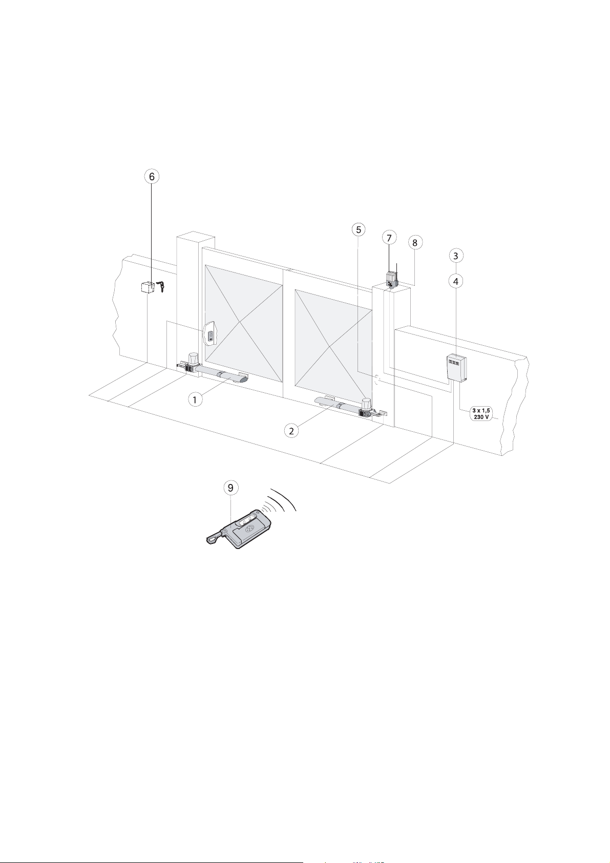
INTRODUCTION
These instructions will show you how to install a KRONO gearmotor external
automatic opening system for wing gates.
Please read these instructions and diagrams carefully before starting any work.
Standard Installation
1) Left-hand motor unit
2) Right-hand motor unit
3) Control panel
4) Radio receiver
5) Safety photocell
6) Key-operated selector switch
7) Flashing light
8) Receiving antenna
9) Radio transmitter
UNDER NO CIRCUMSTANCES SHOULD THIS EQUIPMENT BE OPERATED UNLESS FITTED TO A GATE.
FAILURE TO COMPLY WILL INVALIDATE THE GUARANTEE.
Page 3

2
INSTALLATION INSTRUCTIONS
CONTENTS
1) Stage 1:- Civil & Mechanical Section Page
1.1 BASIC HINGE GEOMETRY 3
1.2 BASIC CABLE LAYOUT 4
1.3 LOW VOLTAGE CABLE LAYOUT 5
1.4 ATTACHING THE REAR BRACKET 6
1.5 ATTACHING THE BRACKETS 8
2) Stage 2:- Wiring & Electrical
2.1 INSTALLING THE MOTORS 10
2.2 INSTALLING CENTRE STOPS 11
2.3 MANUAL RELEASE OF GATES 12
2.4 FITTING THE CONTROL PANEL IN THE CASING 13
2.5 WIRING THE MOTORS 14
2.6 WIRING THE SAFETY PHOTOCELLS 15
2.7 INSERTING THE FREQUENCY CARD 15
2.8 WIRING IN THE TUNED ANTENNA 16
2.9 CODING THE REMOTE CONTROLS 16
2.10 POWERING UP THE CONTROL PANEL 17
3) Stage 3:- Commissioning the Control Panel
3.1 INITIAL WIRING & CONTROL PANEL SETUP 18
3.2 OPENING & CLOSING THE GATES 19
3.3 CONTROL PANELADJUSTMENTS 20
3.4 AUTOMATIC CLOSE & SAFETY PHOTOCELLS 21
3.5 PROGRAMMING THE REMOTE CONTROLS TO THE CONTROL PANEL 22
4) Troubleshooting Guide 24
5) Technical Information
5.1 MOTOR TORQUE SETTINGS 26
5.2 ZA4 CONTROL PANEL DESCRIPTION 27
5.3 ZA4 WIRING DIAGRAM 28
5.4 CONTROL PANELADJUSTMENTS 29
5.5 ELECTRICAL CONNECTIONS 30
7) Contact Information
“Time marches on but Came automation equipment stands the test of time...”
Page 4

3
STAGE 1
CIVIL & MECHANICAL SECTION
1.1 - Basic Hinge Geometry
Before beginning your installation of your KRONO system, check the following:
• Your gate piers or posts are sufficiently strong enough to support the gates and operators and the
gates swing freely and there is no friction between the moving parts.
• Measurement C must not be greater than the value shown below. If this is the case, it is necessary
to modify the pillar so that this measurement corresponds.
Dimension C must be no greater than 60mm for 90° opening and no greater than 50mm for a 120°
opening.
• Ensure that a centre stop is securely cemented into the ground. As a guide ensure that the centre
stop protrudes no more than 65mm. Any higher and it might catch the underside of a car.
Figure 1
Centre Stop
Pillar Pillar
Hinge Hinge
C C
Page 5

4
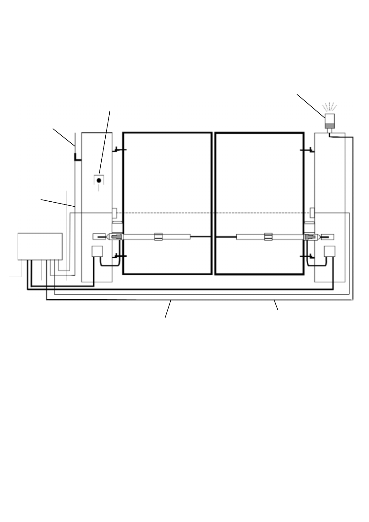
1.2 - Basic Cable Layout
This diagram details the basic cable layout for a pair of motors.
The power supply to the control panel should be live and protected in accordance with the 16th edition
electrical regulations. The supply should be rated at a minimum of 6 amps. When installing wires
outdoors the cable approach to all devices must be from below to create a ‘drip-loop’ and thereby
avoid unneccessary water ingress.
Fig 2
When installing low voltage cable around the gateway it is advised to put all low voltage cable in either
ducting ot alkathene piping. All cable jointing should be carried out above ground.
Control panel
housing
240V AC
4 core
1.5mm SWA
4 core
1.5mm flex
Joint box
Page 6
5
1.3 - Low Voltage Cable Layout
All CAME accessories can be wired 0.2m stranded cable (burglar alarm type). The tuned antenna
should be wired with coaxial cable (RG59).
Fig 3
Tuned
Antenna
Flashing
light
Keyswitch
Doc-E safety
beams
2 core
1mm
8 core 0.2mm stranded
cable to all safety beams
Coaxial
cable
Page 7
6
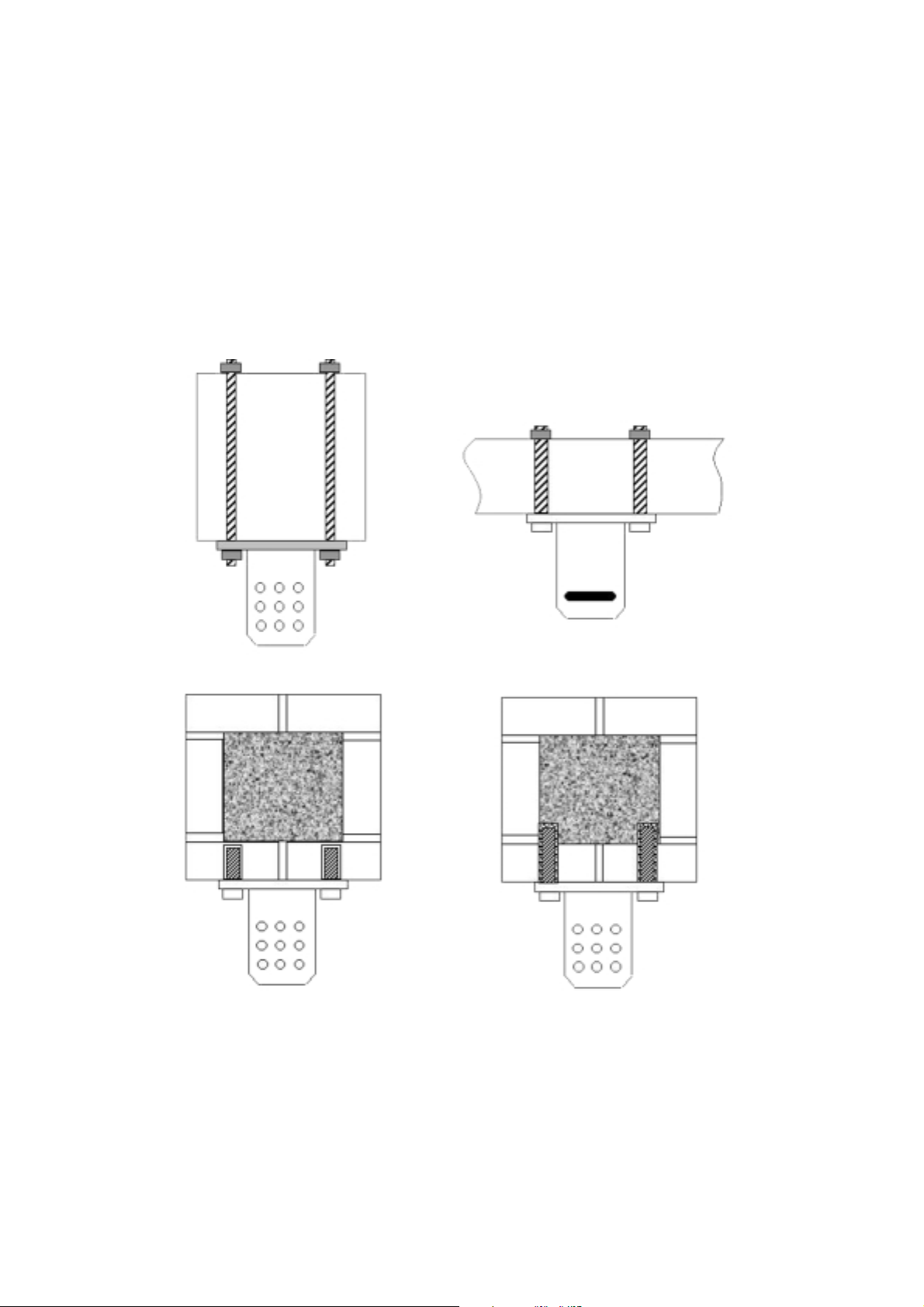
1.4 - Attaching the Rear Bracket
The rear bracket can be lengthened or shortened to suit individual installations, site and the position
of the gate (with respect to the bracket).
When attaching the rear bracket to the post or pillar use suitable expansion bolt or chemical fixings. If
fitting to a wooden post it is advised to use threaded bar bolted through the post for added strength.
Fig4
Wooden post and gate
Brick pillars
Page 8
7
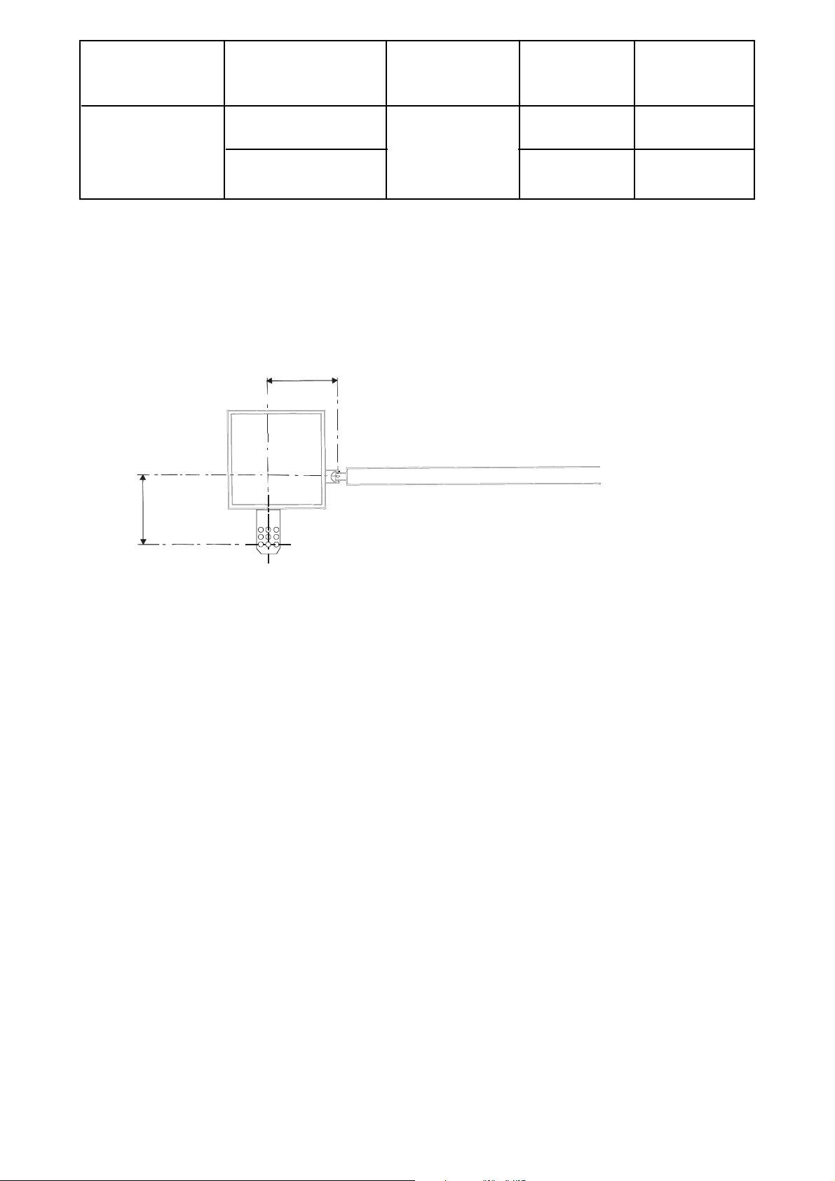
Type Opening A B C
Angle mm mm mm
90° 130 60
KRONO 130
120° 110 50
Attach the rear bracket while respecting distances Aand B between the hinge on the gate and the hole
in the centre of the bracket (which is used to hold the gear motor). To make the operation easier, the
KRONO installation kit contains two cardboard templates (for 90° and 120° openings). the rear bracket
is equipped with additional hole to make the fitting of the motor easier, or to change the opening angle
of the gate.
Fig 5
A
B
Page 9

8
1.5 - Attaching the Brackets
With the gate closed, install the front bracket on the gate wing. The front bracket, when installed, must
be aligned along the horizontal axis of the rear bracket (see figure) and the distance between the
centre axes of the brackets must be 910mm.
Rear bracket
Levelli ng the brackets
Front bracket
E = 910
Fig 6
Page 10

9
END OF INSTALLATION STAGE 1
BEFORE STARTING STAGE 2 - Wiring and Electrical
PLEASE CHECK THAT YOU HAVE CORRECTLY:
Ref Page
1. Prepared the cabling correctly 1.2 4
2. Correctly attached the brackets 1.4 6
NOW STAGE 1 IS FULLY COMPLETED YOU ARE READY TO BEGIN
STAGE 2 OF YOUR KRONO AUTOMATION KIT INSTALLATION.
Page 11

10
STAGE 2
WIRING AND ELECTRICAL
2.1 - Installing the Motors
Fit the motors to the brackets with the nuts and bolts provided. Ensure that the metal insert is inserted
into the rear bracket to ensure free movement.
Make sure that there is no interference between the motor shaft and the gate wing at any point in the
gate travel. If interference is found, lengthen the front bracket to the minimum length that provides
interference-free operation.
,
5
h
r
t
t
Fig 7
us
Screws
Screws 3,9
35
Screws 3,9
u
9
9,
ashe
u
Page 12

11
2.2 - Installing Centre Stops
Install a centre stop and an open/stop securely in the ground to prevent the gate wing frome exceeding
its’ maximum travel at the open and closed position.
Fig 8
DoorstopGate wing
Doorstop (only for KR300 D/
S)
Page 13

12
2.3 - Manual Release
In the event of a power failure, use the key to release the locking system. Insert key (A) in the keylock,
turn it to allow the release lever (B) to unlock and remove the key (fig 9 - 10); then turn the release
level 90° in either direction (fig 11).
To relock the door, reset the release lever to the initial position (fig 12).
Fig 5
Fig 9 Fig 10
Fig 11 Fig 12
Fig 2
Fig 3
A
B
Fig 4
Page 14

13
2.4 - Fitting the Control Panel in the Casing
Securely fasten the control panel PCB to the
casing with the screws supplied.
Plug the green connector from the transformer to
the PCB ensuring that it connects the correct way .
NB FROG Series Motors:
connect the black wires
coming out of the board to one capacitor and the
red wires to the other.
Screws
Screw positioning holes
Green connector point
Fastening screws
Page 15

14
2.5 - Wiring the Motors
Wire the gear motor by following the wiring diagram on the label which is fastened to the gear motor
(fig 13).
For the cable connection, use the appropriate cable clamp (part A) supplied, fixing it to the capacitor
support (part B).
2.6 - Wiring in the Safety Photocells
Safety beams should be fitted approximately 15 inches fom ground level.
If fitting a second arc line of safety beams then C & NC must be wired in ‘series’.
Fig 13
Fig 14
Fig
Ground
U/XV/YW
Terminal block
U
VW
Part. A
10
C1
2
Part. B
TX
2
-
10 2 TX C NC
Page 16

15
2.7 - Inserting the Radio Frequency Card
Insert the radio frequency card into the small socket on the control panel (ensure that the power is
turned OFF to the control panel before inserting the frequency card).
2.8 - Wiring in the Tuned Antenna
ANTENNA WIRING
POINT
Fig 15
Fig 16
ANTENNA WIRING
POINT
ZA4
Page 17

16
2.9 - Coding the Remote Controls
T432S (MINI-PINK) Remotes
Remove the battery cover off of the remote and change the Factory set code to a unique code for the
installation via the 10 dipswitches.
Insert the frequency card into the control panel (item 5 on motherboard). Identify the little yellow button
on the motherboard and press and hold the little yellow button in and an LED will flash. Then press
the button on the remote control you wish to operate the equipment with and then let go of both
buttons. Make sure any additional remotes are the same code. You do not have to program these into
the board - they should work.
Channel 1
Channel 3
Channels
selection
jumpers
Code selection
dipswitch:
set the same
code
programmed
on receiver
actionning LED
4 pins strip
1st key fixed
on channel 1
2nd key preset on
channel 2; put the
jumpers as shown in
figures to change
Channel 4
Channel 2
Channels Scheme
Fig 17
"AF" BOARD
- T.C.A .
-
OFFON
NS. -
MOTHERBOARD
1ON2345678910
Page 18

17
2.10 - Powering up the Control Panel
Connect protected mains power to terminals L1 + L2 in the control panel (L2 being LIVE!). Ensure that
the control panel is adequately earthed.
END OF INSTALLATION STAGE 2
BEFORE STARTING STAGE 3 - Installation
Commissioning the Control panel
PLEASE CHECK THAT YOU HAVE CORRECTLY:
Ref Page
1. Installed Motors 2.1 10
2. Installed Centre Stops 2.2 11
3. Checked Manual Release 2.3 12
4. Fitted the Control Panel in the Casing 2.4 13
5. Wired the Motors 2.5 14
6. Wired the Safety Photocells 2.6 14
7. Inserted the Frequency Card 2.7 15
8. Wired the Tuned Antenna 2.8 15
9. Coded the Remote Controls 2.9 16
10.Powered up the Control Panel 2.10 17
NOW STAGE 2 IS FULLY COMPLETED YOU ARE READY TO BEGIN
STAGE 3 OF YOUR KRONO AUTOMATION KIT INSTALLATION.
Page 19

18
STAGE 3
COMMISSIONING THE CONTROL PANEL
3.1 - Initial Wiring & Control Panel Setup
1. Connect power terminals L1 - L2
and a suitable earth (L2 being LIVE!)
2. Select the motor power setting on the
transformer to level 1 for
commissioning.
3. Ensure that the motors are adequetely
earthed.
Fig 18
Fig 19
ZA4
Page 20

19
ON
1. Momentarily pulse terminals 2 & 3 with a
piece of wire trailing from terminal 2 and
momentarily touching terminal 3.
The gates should start to open. If they start
to close turn the power off to the control
panel and change around either U-V (motor
1) or X-Y (motor 2) to change the motor
direcrion.
2. Once you have proven the motor direction
use terminals 2 & 7 to open and close the
gates with a trailing wire once again into
terminal 2, momentarily touching terminal 7.
5. Select dipswitches 1 & 2 OFF for
commissioning.
6. Ensure hard wire link is fitted between
terminals 1 & 2 and 2 & C1.
3.2 - Opening & Closing the Gates
Fig 20
Fig 21
Fig 22
Fig 23
OFF
L1 L2 U V W X Y E1 10 11 1 2 3 5 7 C1
L1 L2 U V W X Y E1 10 11 1 2 3 5 7 C1
L1 L2 U V W X Y E1 10 11 1 2 3 5 7 C1
Page 21

3.3 - Control Panel Adjustments
1. To delay one gate leaf, adjust potentiometer TR2M to delay the closing of gate no.2 in the closing
cycle.
2. T
o set the total running time of the motors, adjust potentiometer TLto allow the motors to run for
a further 5-7 seconds after the movement cycle has been completed (ie fully open or fully
closed).
3. Check the sensitivity
of the gates by trying to
physically stop the gate and adjust the power
settings on the transformer accordingly. If more
power is needed for heavier gates then switch off
power and move transformer wire up to setting 2.
For rechecking sensitivity, repeat process up to 3 or
4 if even more power is needed.
20
Fig 24
Fig 25
Fig 26
Trimmer TR2M
Trimmer TL
Page 22

21
3.4 - Automatic Close & Activating
Safety Photocells
1. To select automatic closing, select dipswitch 2 ON.
Set the automatic closing time by adjusting potentiometer TCA.
Fully anti-clockwise will automatically close the gates after approximately 10 seconds and fully
clockwise will close the gates after approximately 80 seconds. Asensible setting is about halfway (ie
6 o’clock position) which will automatically close the gates after approximately 30 seconds.
2. For re-opening during closing.
Remove hard wire link
between 2 & C1 and insert safety beam wires as
shown.
TRIMMER TCA
6 O’CLOCK POSITION
Fig 27
Fig 28
Fig 29
ON
1
1
OFF
10 11 1 2 3 5 7 C1
10 2 NC
Page 23

22
3.5 - Programming the Remote Controls to the
Control Panel
To use the remote control system, proceed as follows:
A) Turn power OFF and insert AF radio frequency board then turn power back on
B) Code the transmitter. See the relevant instruction sheet
(See Fig 11)
C) To store the code on the circuit board Proceed as follows:
Press and hold down the programming button on the radio receiver card (the signal
LED will start to flash)
At the same time transmit on the top button of your remote control; keep both the top
button and the yellow receiver button pressed until the LED stops flashing and remains
on constant. It will then go out to indicate that the code has been successfully
stored.
N.B. If you wish to change the code on your transmitter in the future,
simply repeat the procedure above with all the remotes on the
installation.
W ARNING: Disconnect the power supply from the control board before inserting
OR removing the AF radio-frquency card from the socket.
Page 24

23
END OF INSTALLATION STAGE 3
PLEASE CHECK THAT YOU HAVE CORRECTLY:
Ref Page
1. Set power setting, inserted motor 3.1 17
capacitors, set dipswitches for
commissioning, ensure wire link is fitted
between terminals 1 & 2 and 2 & C1.
2. Set the opening and closing times 3.2 18
for gates.
3. Adjusted the control panel. 3.3 19
4. If required, activated automatic closing 3.4 20
and safety photocells.
5. Programmed the remote to the 3.5 21
control panel.
Page 25

24
4. TROUBLESHOOTING GUIDE
A MULTIMETER WILL BE NEEDED
PROBLEM
GATE WILL NOT RESPOND
WHEN GIVEN ACOMMAND
GATES ARE OPEN BUT
WILL NOT CLOSE AND
GREEN LED IS FLASHING
WHEN COMMISSIONING GATE
AUTOMATICALLY OPENS BUT
DOES NOT AUTOMATICALLY
CLOSE
1. CHECK POWER SUPPLY TO THE
CONTROL PANEL.
2. CHECK CONTROL PANEL FUSES.
3. CHECK HARD WIRE LINK FITTED
BETWEEN TERMINALS 1 & 2.
4. CHECK THAT CAPACITORS ARE
FITTED AND WIRED CORRECTLY.
1. CHECK SAFETY BEAMS ARE WIRED
CORRECTLY. (IF MORE THAN ONE
SET OF BEAMS ARE FITTED THEY
MUST BE WIRED IN SERIES.)
2. CHECK THAT THERE IS POWER
GOING TO THE BEAMS, IF NOT
RESTORE POWER.
3. IF SAFETY BEAMS ARE NOT FITTED
ENSURE THATA HARD WIRE LINK IS
FITTED BETWEEN TERMINALS 2 & C1
4. REMOVE SAFETY BEAM WIRES 2 &
C1 FROM CONTROL PANELAND
CHECK IF YOU HAVE A NORMALLY
CLOSED CIRCUIT COMING FROM
THE BEAMS.
1. MOTOR WIRES ARE WRONG WAY
ROUND. CHECK AND PROVE MOTOR
DIRECTION BY MOMENTARILY PULSING
TERMINALS 2 & 3. THE GATE SHOULD
OPEN UP. TURN AUTOMATIC CLOSING OFF
(DIP SWITCH 2) UNTIL MOTOR DIRECTION
HAS BEEN PROVEN.
SOLUTION
Page 26

25
PROBLEM
IF THE PROBLEM IS STILLAPPARENT CONTACT THE
CAME TECHNICAL HELPLINE:
0115 921 0430
GATES WILL NOT RESPOND TO
REMOTE CONTROL
COMMAND
1. AF FREQUENCY CARD NOT FITTED TO
CONTROL PANEL.
2. REMOTE CONTROL HAS NOT BEEN
PROGRAMMED INTO THE CONTROL
PANEL.
3. REMOTE CONTROL HAS THE WRONG
CODE SETTING.
4. “OPERATOR PRESENT” HAS NOT BEEN
SELECTED TO DEACTIVATE RADIO
REMOTE CONTROLS (DIPSWITCH 1).
5. WRONG FREQUENCY CARD FITTED
FOR THE REMOTE CONTROL.
SOLUTION
THIS INSTALLATION WAS COMPLETED BY:
.........................................................................
NAME..............................................................
ADDRESS........................................................
.........................................................................
.........................................................................
.........................................................................
TEL........................ MOBILE............................
DATE OF INSTALLATION................................
Page 27

26
5. TECHNICAL INFORMATION
5.1 - Motor Torque Settings
To vary the motor torque, move the indicated spade connector to one of the four position :
1=min, 4=max.
N.B. It is always best to start from position one and increase the torque setting as required.
Fig 30
ZA4
Page 28

27
5.2 - ZA4 Control Panel Description
Description of Control Panel:
Micro-processor controlled electrical cabinet powered by 230V (a/c) at 50-60Hz, single phase.
Designed for control of CAME (ATI/FERNI/FROG), for hinged gates, hinged industrial doors.
Designed and built entirely by CAME to meet UNI8612 safety standards at an IP 54 level of protection.
Housing made of ABS is equipped with vents to provide internal air circulation. Guaranteed for 3
years, unless tampered with. This control panel is powered 230V a.c across terminals L1 and L2, and
is protected by a 5A fuse on the main power line. Control systems are powered by low voltage and
protected by a 2A fuse. The accessories total wattage (24V) must not exceed 20W.
The control panel and motors should be suitably earthed.
Safety:
SAFETY BEAMS CAN BE CONNECTED TO OBTAIN:
Re-Opening: During closing (2-C1), if the beam is broken while the gate is closing, they will reverse
the direction of movement until the gate is completely open and will stay open until the
obstacle is removed.
Total Stop: (1-2) Creates immediate stop of gate movement without automatic closing: (a
pushbutton or radio remote control must be actuated to resume movement).
N.B IF A NORMALLY CLOSED SAFETY CIRCUIT (2-C1, 1-2) IS OPENED, THE L.E.D
WILL FLASH TO INDICATE THE FACT THAT THE BEAM IS BROKEN.
Accessories that can be Connected to this Unit:
“Gate in Motion” Lamp: The lamp that lights the manoeuvering zone:
it remains lit from the the moment the gate begins to open until they are
completely closed (including the time required for the automatic closure).
When automatic closure is not enabled, the lamp remains lit only during
movement (E-E3).
Other functions available:
Automatic closing: The automatic closing timer is automatically activated at the end of
the opening cycle. The pre-set, adjustable automatic closing time is
automatically interrupted by the activation of any safety system, and
is deactivated after a STOP command or in case of power failure.
“Operator present” function: Gate operates only when the pushbutton is held down (the radio
control system is deactivated)
Page 29

28
5.3 - ZA4 Wiring Diagram
Fig 31
Tuned antenna
1 control panel
1 frequency card
1 pair safety
beams
Remote control
transmitter
Two KRONO motors
Fig 32
230V A/C
M1
Single-Phase motor
M2
Single-Phase motor with leaf delay
on closing cycle
Terminals 1 and 2, 2 and C1 are normally closed circuits and if
they are not used they must be linked
L1 L2 U V W X Y E1 10 11 1 2 3 5 7 C1
Co-axial cable
2
TX
Safety beams which are connected to obtain Re-opening
During the closing cycle
-
10 2 TX C NC
Page 30

29
5.4 - Control Panel Adjustments
Trimmer T.L - Adjustment of operating time from a minimum of 0 seconds to a maximum of 120
seconds N.B. it is advised to let the motors run on for between 6 and 8 seconds after the last gate has
fully close.
Trimmer T.C.A - Adjustment of automatic closing time from a minimum of 1 to a maximum of 120
seconds.
Trimmer T.R.2.M - Partial opening time adjustment and delay in closing of the second motor leaf
delay from a minimum of 0 seconds to a maximum of 20 seconds.
T.L
T.C.A
TRIMMERS
ADJUSTMENT
T.R.M2
Fig 33
ZA4
Page 31

30
5.4 - Electrical Connections
Power supply for control panel
Connection for motor one (delay in opening)
Connection for motor two (delay on closing)
230V (A.C) 25W max output in motion (e.g. flashing light)
“Gate Open” signal light (24V 3W max)
24V (A.C) Output power supply to accessories (max 20W)
Stop button (N.C)
Open only button (N.O)
Contact for radio and or pushbutton control for open-close
Contact (N.C) for re-opening during closing
Antenna connection
L1 L2 U V W X Y E1 10 11 1 2 3 5 7 C1
L1
L2
U
W
V
X
W
Y
W
E1
10
5
10
11
1
2
2
3
2
7
2
C1
Page 32

CONTACT INFORMATION
CAME UNITED KINGDOM LTD
UNIT 3
ORCHARD PARK INDUSTRIAL ESTATE
TOWN STREET, SANDIACRE, NOTTINGHAM NG10 5BP
TEL: 0115 921 0430
FAX: 0115 921 0431
INTERNET : www.cameuk.com
E-MAIL: enquiries@cameuk.com
THIS INSTALLATION WAS COMPLETED BY:
.........................................................................
NAME..............................................................
ADDRESS........................................................
.........................................................................
.........................................................................
.........................................................................
TEL........................ MOBILE............................
DATE OF INSTALLATION................................
 Loading...