

Page 1
KRONO
Automazione esterna per can cel li a battente
External automatic opening system for wing gates
Automatizacion exterior para puertas batientes
Documentazione
Tecnica
S51
rev. 3.1
09/2005
©
CAME
CANCELLI
ITALIANO / ENGLISH / ESPAÑOL
AUTOMATICI
119DS51-1
9
4 x 1 - RX
2 x 1
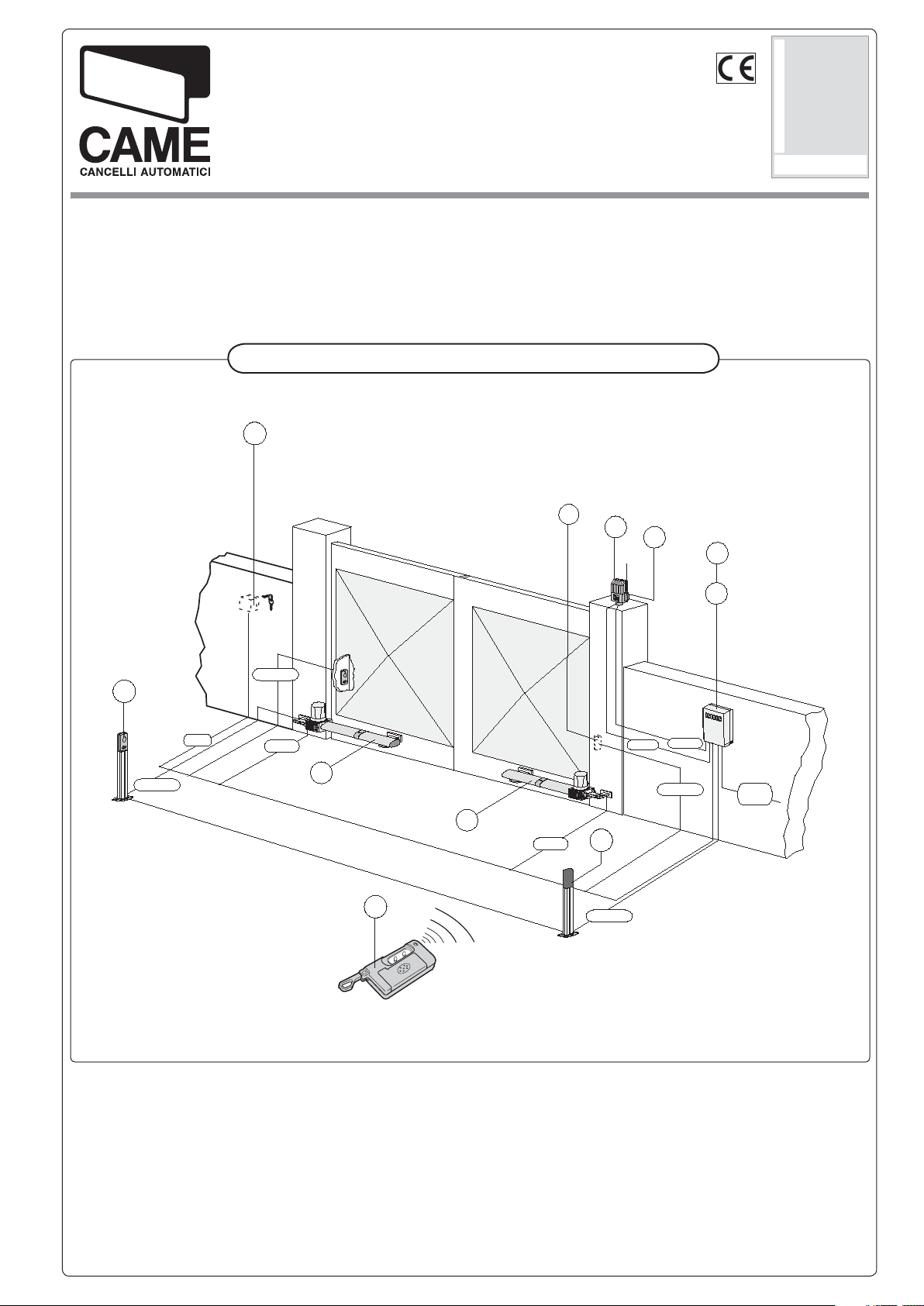
Impianto tipo -
6
2 x 1 - TX
4 x 1,5
1
Standard installation -
2
Instalación tipo
11
5
7
2 x 1,5
4 x 1,5
9
8
4 x 1 - RX
T RG 58
3
4
3 x 1,5
230 V
1) Gruppo motore sx
2) Gruppo motore dx
3) Quadro co man do
4) Ricevitore radio
5) Fotocellula di si cu rez za
6) Selettore a chia ve
7) Lampeggiatore di mo vi men to
8) Antenna di ri ce zio ne
9) Colonnina per fotocel-lula
10) Trasmettitore radio
10
1) Left-hand motor unit
2) Right-hand motor unit
3) Control panel
4) Radio reveicer
5) Safety photocell
6) Key-operated selector switch
7) Flashing light
8) Receiving antenna
9) Photocell column
10)Radio transmitter
2 x 1 - TX
1) Conjunto motor izq.
2) Conjunto motor der.
3) Cuadro de mandos
4) Radiorreceptor
5) Fotocélula de seguridad
6) Selèctor con llave
Lámpara intermitente
7)
8) Antena de recepción
9) Columna para fotocélula
10) Transmisor
Page 2
ITALIANO
CARATTERISTICHE GENERALI
DESCRIZIONE:
- Automazione esterna per cancelli a battente;
- Progettato e co stru i to in te ra men te dal la CAME S.p.A., rispon-
de alle vi gen ti nor me di si cu rez za in vigore, con gra do di pro tezione IP 54;
- Garantito 12 mesi salvo manomissioni.
ITALIANO - ENGLISH - ESPAÑOL
VERSIONI:
KR 300 S
Versione sinistra;
KR 300 D
Versione destra;
KR 510 S
Versione sinistra con fi necorsa in apertura e chiusura;
KR 510 D
Versione destra con fi necorsa in apertura e chiusura.
IMITI D'IM PIE GO:
L
- Dimensione ante fi no a 3 metri;
- Apertura dell’anta: max 120°;
- I valori indicati (vedi tab. 2 a pag. 3) sono validi per un servi-
zio ad uso residenziale; per un servizio intensivo ri dur re tali
valori dal 10 al 20%.
KR 310 S
Versione sinistra con fi necorsa in apertura e chiusura;
KR 310 D
Versione destra con fi necorsa in apertura e chiusura.
ENGLISH
GENERAL SPECIFICATIONS
DESCRIPTION:
- External automating opening system for wing gates;
- Designed and built entirely by CAME S.p.A., it meets the
regulations in force, with IP54 protection level;
- Guaranteed for 12 months, unless tampered with by
unauthorized personnel.
V
ERSIONS:
KR 300 S
Left side model ;
KR 300 D
Right side model ;
KR 310 S
- Version left with end-stop during opening and closing;
KR 310 D
- Right version with end-stop during opening and closing;
CCESSORI:
A
KR001
Serratura a chiave personalizzata.
KR 510 S
- Version left with end-stop during opening and closing;
KR 510 D
- Right version with end-stop during opening and closing;
PERATIONAL LIMITS:
O
- Door height up to 3 meters;
- Maximum opening of wing: 120°;
- The values shown (see table 2 on page 3) refer to normal
residential use; for more intensive use, these values should be
reduced by 10 to 20%.
CCESSORIES:
A
KR001
Personalised key lock.
ESPAÑOL
CARACTERÍSTICAS GENERALES
DESCRIPCIÓN:
- Automatizacion exterior para puertas batientes;
- Completamente diseñado y fabricado por CAME S.p.A.,
responde a las normas de seguridad vigentes, con clase de
protección IP 54;
- Garantizado 12 meses, salvo manipulaciones.
ODELOS:
M
KR 300 S
Versión izqierda;
KR 300 D
Version derecha;
KR 310 S
Versión izqierda con fi nal de carrera en apertura y cierre;
KR 310 D
Version derecha con fi nal de carrera en apertura y cierre.
2
KR 510 S
Versión izqierda con fi nal de carrera en apertura y cierre;
KR 510 D
Version derecha con fi nal de carrera en apertura y cierre.
IMITES DE EMPLEO:
L
- Dimensión hojas hasta 3 metros;
- Apertura standard máxima de la hoja: 120°;
- Los valores indicados (ver tab. 2 - pag. 3) valen para el uso
residencial; para un servicio más intensivo es preciso reducir
dichos valores de 10 al 20%.
CCESORIOS:
A
KR001
Cerradura con llave personalizada.
Page 3
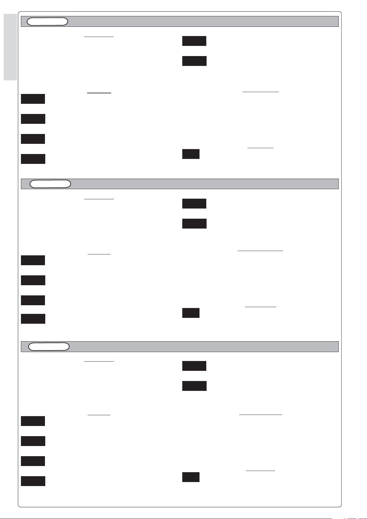
Tab. 1
CARATTERISTICHE TECNICHE -
TECNICHAL CARACTERISTICS
- CONTROLES GENERALES
6
MOTORIDUTTORE
GEARMOTOR
MOTORREDUCTOR
GRADO DI
PROTEZIONE
PROTECTION
RATING
GRADO DE
PROTECCION
PESO ALIMENTAZIONE ASSORBIMENTO POTENZA
WEIGHT POWER SUPPLY CURRENT POWER DUTY CICLE PUSH TRAVEL TIME CAPACITOR
PESO ALIMENTACION ABSORBENCIA POTENCIA
KR3 IP 54 10 Kg 230V a.c. 1,1 A 130W 30 %
INTERMITTENZA
LAVORO
INTERMITENCIA
TRABAJO
SPINTA TEMPO CORSA CONDENSATORE
EMPUJE
* Max
3000 N
TIEMPO DE
RECORRIDO
22 s (90°) 8 µF
KR5 IP54 12 kg 230V a.c. 1,1 A 130W 30 % 3000 N 34 s (90°) 8 µF
* Ottenuta mediante quadro comando CAME
* Obtained with CAME control panel
* Empuje regulable obtenido mediante tablero de control CAME
Tab. 2
LIMITI D'IMPIEGO -
KR3
Larghezza anta
Width of gate wing
Ancho puerta
m 2.00 Kg 800
m 2.50 Kg 600
m 3.00 Kg 400
USE LIMITS -
Peso anta
Weight of gate wing
Peso puerta
LIMITES DE EMPLEO
Larghezza anta
Width of gate wing
Ancho puerta
m 2.00 Kg 1000
m 2.50 Kg 800
m 3.00 Kg 600
KR5
Peso anta
Weight of gate wing
Peso puerta
m 4.00 Kg 500
ITALIANO - ENGLISH - ESPAÑOL
CONDENSADOR
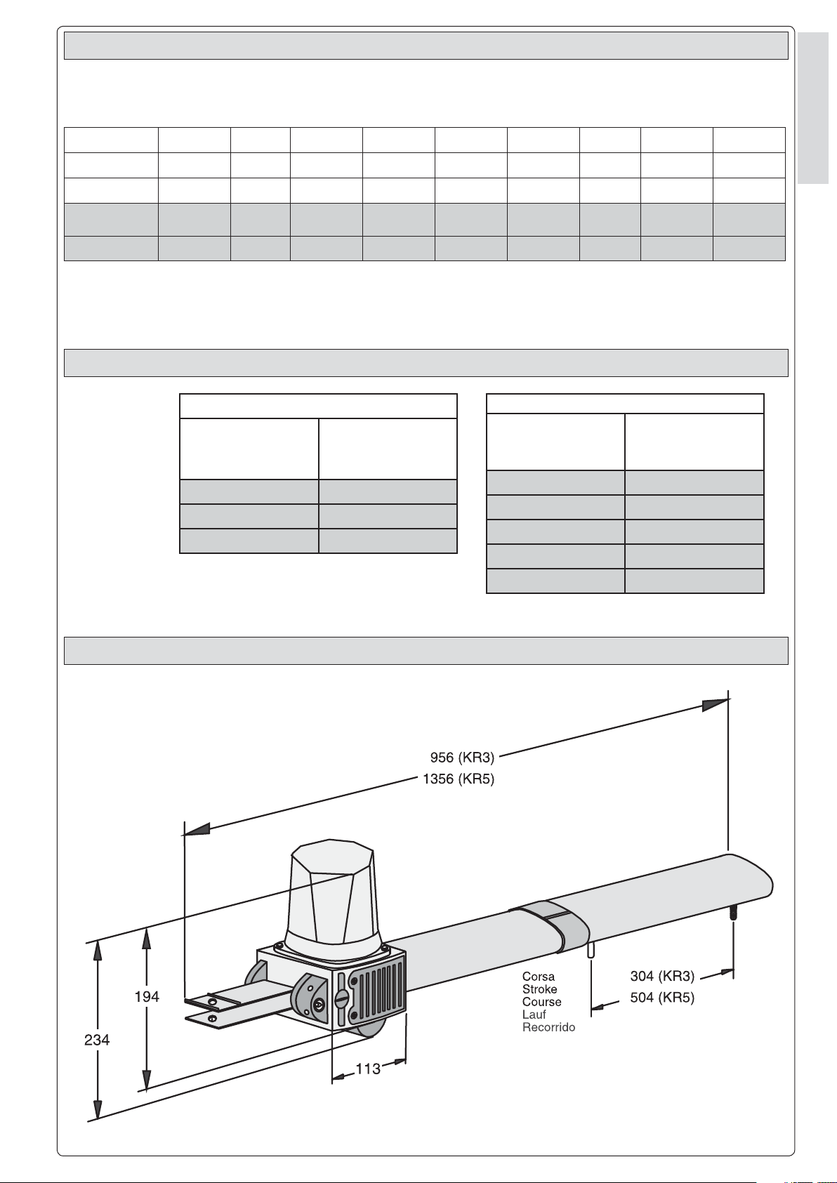
MISURE D'INGOMBRO -
EXTERNAL DIMENSIONS
m 5.00 Kg 400
- DIMENSIONES
.6
3
Page 4

CONTROLLI GENERALI -
GENERAL CONTROL PROCEDURE -
CONTROLES GENERALES
Controllare che:
- la struttura del can cel lo sia ade gua ta men te ro bu sta e che i car di ni
si a no lu bri fi ca ti;
- la misura C non sia superiore al
valore in di ca to nella “tab. 3” pag.
4, in caso con tra rio è ne ces sa rio
ITALIANO - ENGLISH - ESPAÑOL
in ter ve ni re sul pi la stro in modo da
rag giun ge re tale mi su ra.
C
Tab. 3
TIPO
TYPE
TIPO
- the structure of the gate is suitably
- the measure C is not above the
MONTAGGIO -
APERTURA
OPENING
ANGLE
APERTURA
Make sure:
strong and the hinges are lubricated;
value indicated in the “tab. 3” pag. 4,
otherwise it is necessary to intervene
on the pillar so as to reach this
measure.
Pilastro
Pillar
Pilier
Pfeiler
Pilar
Cerniera
Hinge
Charniére
Scharnier
Bisagra
ASSEMBLY
A
mm
- MONTAJE
B
mm
Comprobar que:
- la estructura de la cancela sea
robusta y las bisagras estén
lubricadas;
- la medida C no sea superior al
valore indicado en la “tab. 3” pág.
4, en caso contrario es necesario
reducir el pilar para alcanzar tal
medida.
Anta
Leaf
Vantail
To r
Hoja
C
mm
Battuta d'arresto
Gate stopper
Arrét
Toranschlag
Tope
E
mm
KR3
KR5
1
B
Fissare la staffa di coda ri spet tan do le quote A e B (Tab. 3) tra il
car di ne del can cel lo e il foro cen tra le della staffa (sul la quale deve
es se re fi s sa to il mo to ri-duttore).
La staffa di coda è do ta ta di ul te rio ri forature per agevolare il
mon tag gio del motori-duttore o
per va ria re l’an go lo di aper tu ra del
cancello. A se con da del l’in stal la zio ne e del la po si zio ne del car di ne
del can cel lo (ri spet to al pi la stro) è
pos si bi le al lun ga re o ac cor cia re la
staffa di coda.
90°
130
120° 110 50
90° 200 200 120 1310
130° 200 140 70 1310
130 60
910
A
Install the rear bracket while respecting distan-ces A and B (Tab. 3)
between the hinge on the gate and
the hole in the centre of the bracket
(which is used to hold the gear motor).
The rear bracket is equipped with
additional holes to make installation
of the gear motor easier, or to change
the opening angle of the gate.
The rear bracket can be lengthened or
shortened to suit the individual installation site and the position of the gate
hinge (with respect to the pillar).
Fijar en soporte trasero respetando
las medi-das A o B (Tabla 3) entre
el gozne de la puerta y el agujero
central del soporte (en que se debe
fi jar el motorreductor).
El soporte trasero está dotado de
otros agujeros para sim-plifi car el
montaje del motorreductor o para
va riar el ángulo de aper tu ra de la
puerta. En función de la instalación
y de la posición del gozne de la
puerta metálica (con relación al
pilar) es posible alargar o acortar el
soporte trasero.
4
Page 5

2
6
ITALIANO - ENGLISH - ESPAÑOL
E
A cancello chiuso, fi s sa re la staffa di
testa sul l’an ta del cancello, in asse
orizzontale con la staffa di coda e
interasse come in di ca to.
3
Vite M8 x 35
Screws M8 x 35
Boccola
Bush
Casquillo
Tornillos M8 x 35
With the gate closed, install the front
bracket on the gate wing. The front
bracket, when installed, must be
aligned along the horizontal axis of
the rear bracket (see fi gu re) and the
distance between the centre axes of
the brackets must be .
Viti ø 3,9 x 9,5
Screws 3,9 x 9,5
Tornillos 3,9 x 9,5
Estando la puerta metálica cerrada,
fi jar el soporte delantero en la hoja
de la puerta, en línea horizontal con
el soporte trasero y con la distancia
entre los ejes indicada.
Procedere al mon tag gio del motoriduttore alle due staffe.
Dado M8
M8 nut
Tuerca M8
Install the gear motor on the two brackets.
Rosetta ø 12
ø 12 Washer
Arandela ø 12
Dado M12
M12 nut
Tuerca M12
Montar el motor-reductor en los dos
soportes.
.6
5
Page 6

4
ITALIANO - ENGLISH - ESPAÑOL
Battuta (solo per KR300 D/S)
Doorstop (only for KR300 D/S)
Dispositif d'ar rêt (uniquement pour KR300 D/S)
Anschlag (Stop) - nur bei KR300 D/S
Tope (sólo para KR300 D/S)
Anta
Gate wing
Vantail
Torflügel
Hoja
Battuta
Doorstop
Dispositif d'arrêt
Anschlag
Tope
Prevedere una bat tu ta di ar re sto
mec ca ni co (ben fi s sa ta al suolo) in
chiu su ra per evi ta re l’oltrecorsa anta
moto-riduttore.
COLLEGAMENTO ELETTRICO -
5
Fig 1
Install a mechanical doorstop (which
must be solidly implanted in the ground)
at the closed points of the gate wing to
prevent the gate wing from exceeding its
maximum travel at the open and closed
posi-tions.
ELECTRICAL CONNECTONS
- CONEXIONES ELÉCTRICAS
Disponer un tope (bien fi jado en el
suelo) para el cierre para evi tar que
la carrera de la hoja motorreductor
sobre-pase el umbral.
- Eseguire i col le ga men ti elettrici,
come in di ca to sul l’ap po si ta eti chet ta fis sa ta sul motoriduttore
stes so (Fig. 1);
- per il cavo di col le ga men to utilizzare l’ap po si to pressacavo (part. A) in
do ta zio ne fi ssandolo alla calottina
porta-con den sa to re (part. B).
6
- Wire the gear motor by following the
wiring diagram on the label which is
fastened to the gear motor. (Fig. 1);
- for the cable connection, use the appropriate cable clamp (part. A) supplied, fi xing it to the capacitor support
(part. B).
- Conectar el motorre-ductor como
se in di ca en la etiqueta específi ca
in cor po ra-da al motorreductor
(Fig. 1);
- para el cable de conexión use el
suje-tador de cable (det. A) de serie
fi jándolo a la tapa portacondensador (det. B).
Page 7

REGOLAZIONE FINECORSA -
LIMIT SWITCH ADJUSTMENT
- REGULACIÓN DEL FINAL DE CARRERA
6
Per le regolazioni dei fi necorsa utilizzare un giravite sull’intaglio dell’asta
fi lettata A per l’APER TU RA, sul l’asta
fi lettata C per la CHIU SU RA.
C
A
For the adjustments of the end stops,
use a screw driv er on the notch of
threaded bar A for OPEN ING, on
thread ed bar C for CLO SURE.
KR310 S
KR510 S
KR310 D
KR510 D
Para las regulaciones de los fi nales
de car re ra, utilice un destornillador
en la ranura de la varilla roscada A
para la APERTURA y en la ranura de
la varilla roscada C para el CIERRE.
A
C
ITALIANO - ENGLISH - ESPAÑOL
.6
7
Page 8

SBLOCCO MOTORIDUTTORE -
GEAR RELEASE
- DESBLOQUEO MOTORREDUCTOR
- Inserire la chiave (A) nel la serratura
, ruotar-la per per met te re alla leva
di sbloc co (B) di sganciarsi ed
estrarre la chiave (fi g. 2-3); ruotare
quin di la leva di sblocco di 90° in
ITALIANO - ENGLISH - ESPAÑOL
uno dei due sen si (fi g. 4).
Fig 2
- Insert key (A) in the keylock, turn it to
allow the release lever (B) to unlock
and remove the key (fi g. 2-3); then
turn the release lever 90° in either
direction (fi g. 4).
Fig 3
- Introduzca la llave (A) en la
cerradura, gírela para que la
palanca de dsbloqueo (B) se desenganche y extraiga la llave (fi g.
2-3); entonces gire la palanca de
desblo-queo 90° en una des las
dos direcciones (fi g. 4).
Fig 4
- Per ribloccare l’anta, ri por ta re la
leva di sbloc co nella po si zio ne
iniziale (fi g. 5).
A
B
- To relock the door, reset the release
lever to the initial position (fi g. 5).
Fig 5
- Para volver a bloquear la hoja, coloque nuevamente la palan-ca de
desbloqueo en la posición inicial
(fi g. 5).
8
Page 9

MANUTENZIONE PERIODICA -
PERIODIC MAINTENANCE -
MANTENIMIENTO PERIÓDICO
6
- Lubrifi care la testa traente e i perni
di rotazione;
- Controllare le viti di fi ssaggio;
- Verifi care l'integrita' dei cavi di
col le ga men to.
- Lubricate the drawing head and the
rest pins
- Ceck the clamps screws;
- Ceck the connection cable's soundness.
- Lubrique la cabeza portante y los
pernos de rotación;
- Controle los tornillos de sujeción;
- Controle el estado de los cables de
conexión.
ITALIANO - ENGLISH - ESPAÑOL
.6
9
Page 10

Tut ti i dati sono sta ti con trol la ti con la mas si ma cura. Non ci as su mia mo
co mun que al cu na re spon sa bi li tà per even tua li errori od omissioni.
All data checked with the maximum care. However, no liability is accepted
for any error or omission.
Todos los datos se han controlado con la máxima atención. No obstante
no nos responsabilizamos de los posibles errores u omisiones.
ASSISTENZA TECNICA
NUMERO VERDE
SISTEMA QUALITÀ
CERTIFICATO
800 295830
W
EB
www.came.it
E-MAIL
info@came.it
CAME CANCELLI AUTOMATICI S.P.A.
DOSSON DI CASIER (TREVISO)
(+39) 0422 4940 (+39) 0422 4941
CAME LOMBARDIA S.R.L._____COLOGNO M. (MI)
(+39) 02 26708293 (+39) 02 25490288
CAME SUD S.R.L.
___________________NAPOLI
(+39) 081 7524455 (+39) 081 7529109
CAME (AMERICA) L.L.C.________MIAMI (FL)
(+1) 305 5938798 (+1) 305 5939823
CAME AUTOMATISMOS S.A__________MADRID
(+34) 091 5285009 (+34) 091 4685442
CAME BELGIUM__________________LESSINES
(+32) 068 333014 (+32) 068 338019
CAME FRANCE S.A.____NANTERRE CEDEX (PARIS)
(+33) 01 46130505 (+33) 01 46130500
CAME GMBH________K
ORNTAL BEI (STUTTGART)
(+49) 07 15037830 (+49) 07 150378383
CAME GMBH ____________S
EEFELD BEI (BERLIN)
(+49) 03 33988390 (+49) 03 339885508
CAME PL SP.ZO.O______________WARSZAWA
(+48) 022 8365076 (+48) 022 8369920
CAME UNITED KINGDOM LTD___NOTTINGHAM
(+44) 0115 9210430 (+44) 0115 9210431
 Loading...