

Page 1
SERIE GARD
Documentazione
Tecnica
CANCELLI AUTOMATICI
ROAD BARRIER
G12000
56
rev. 2.0
03/2001
©
CAME
CANCELLI
AUTOMATICI
119G56-GB
Page 2
Description:
GENERAL CHARACTERISTICS
Models:
Optional accessories:
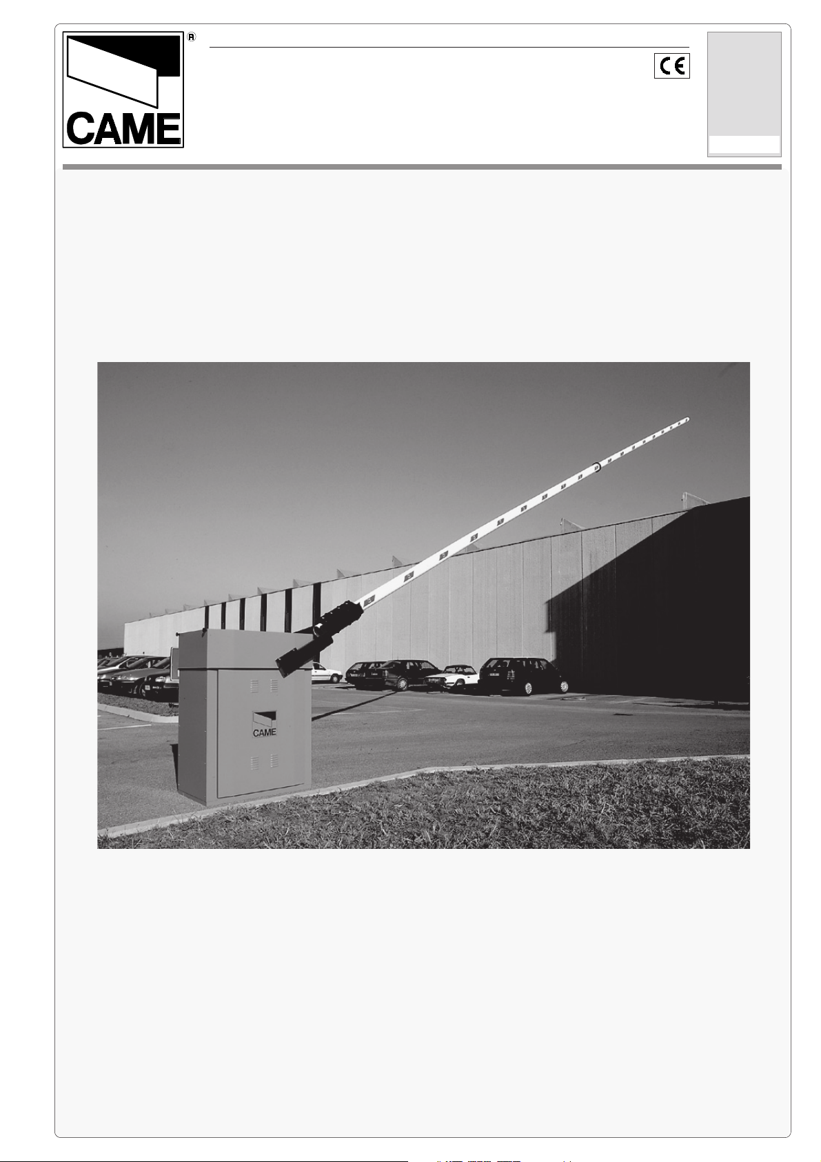
- Motorised barrier for control of
passages with width of up to 12 m.
- Designed and built entirely by
CAME S.p.A., meets UNI 8612 safety
standards, with IP54 degree of
protection.
- Guaranteed 12 months, unless
tampered with.
G12000
Barrier with double, non-reversible 24
V DC gear motor. Galvanised steel
housing with painted finish.
Accessories supplied:
G0121
LB35
Circuit card for installation of an
emergency battery.
G0461
Package of red phosphorescent
strips for the barrier bar.
- Aluminium barrier bar composed of:
Ø120 mm tube with L=6200 mm
Ø100 mm tube with L=6000 mm.
- Hardware and accessories for
mounting the barrier bar.
- Fixed support for the barrier.
II
Important: For easy installation and maintenance, be sure to use CAME original control equipment, safety systems and
II
accessories.
TECHNICAL CHARACTERISTIC
PRODUCT
VERSION
VOLTAGE
REQUIREMENT
CURRENT DRAW
TOTAL MOTOR
POWER RATING
DUTY CYCLE
REDUCTION
RATIO
TORQUE
DURATION OF
OPENING CYCLE
WEIGHT
1.0
230 V A.C.
24 V D.C.
15 A max 300 W 50 % 1/202 600 Nm 10 s 783 kg *
(* Weight of G12000 barrier structure = 250 Kg / Weight of counterweight plates = 500 Kg / Weight of G0121 bar = 33 Kg)
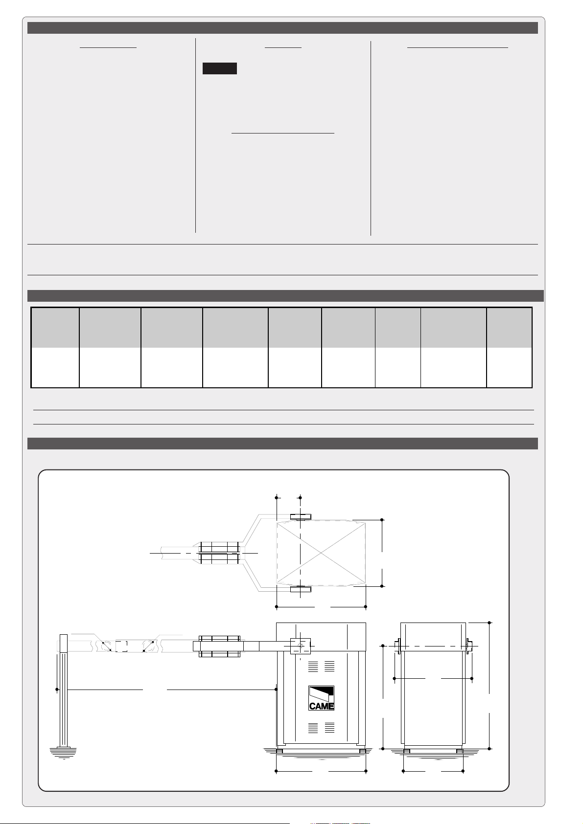
CENTRE LINES AND EXTERNAL DIMENSIONS
235
645
865
ø100
ø120
- pag. - pag.
- pag.
- pag. - pag.
22
- english - - english -
2
- english -
- english - - english -
22
12000
1000
760
1230
580865
Page 3
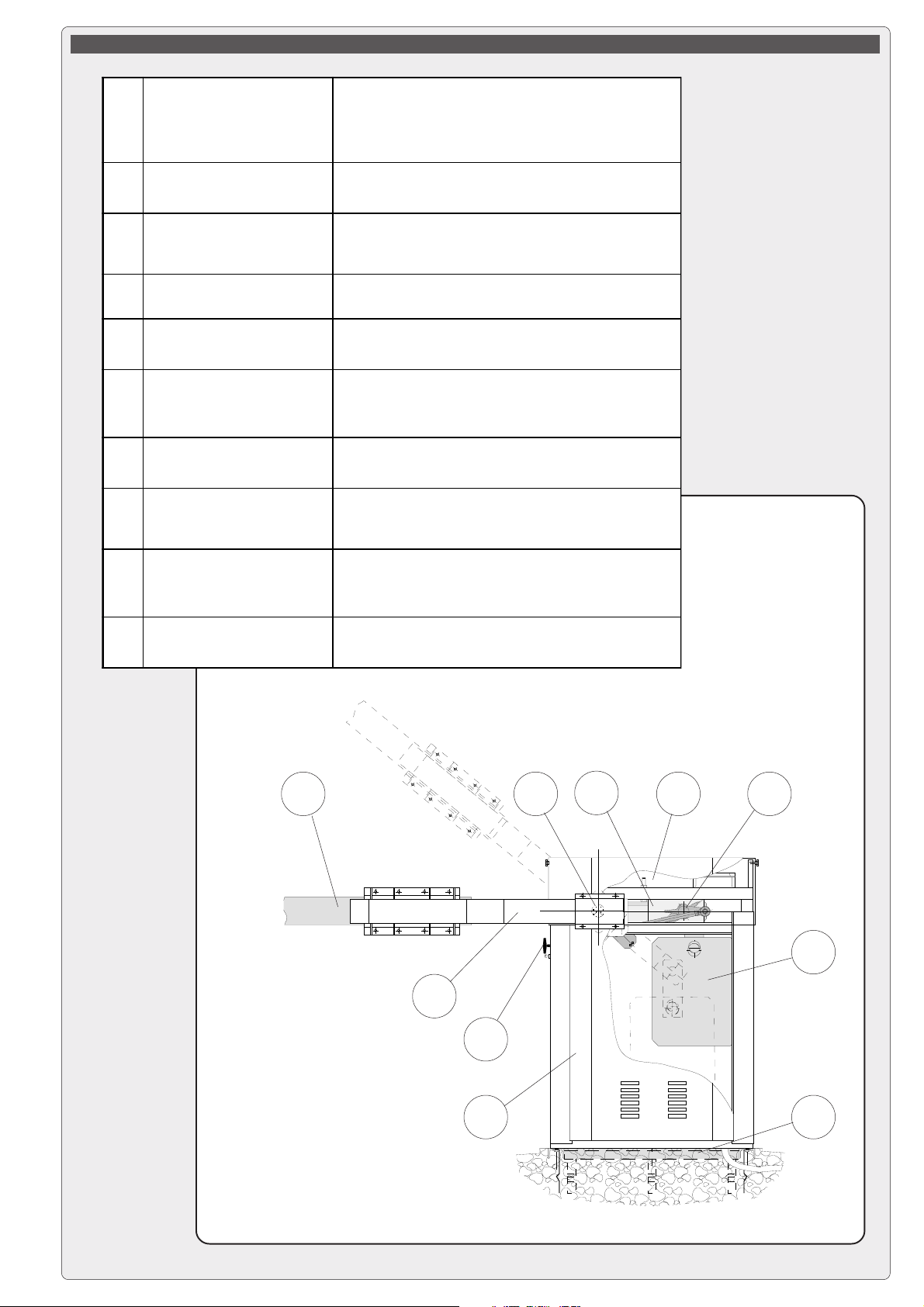
1
REDUCTION GEAR UNIT
DESCRIPTION OF MAIN COMPONENTES
24 VDC motors;
non-reversible reduction gear with die-cast aluminium
housing; uses worm gear reduction system which is
permanently lubricated with liquid grease.
2
TRANSMISSION LEVERS
3
ROTATION SHAFT
COUNTERWEIGHT
4
SYSTEM
5
RELEASE SYSTEM
6
HOUSING
7
MOUNTING BASE
8
BARRIER BAR FORK
9
BARRIER BAR
In forged, galvanised steel; adjustment rods in drawn
hexagonal metal; self-lubricating joints.
In C40 recycled steel, mounted on single-unit
supports with terminal flanges for installation of
barrier bar fork.
Uses 25 Kg rectangular plates which are assembled
as needed.
Manual, with PVC handle and cord in self-lubricating
sheath; safety lock.
Load-bearing structure in steel profiles, and external
cover in press-bent 25/10 sheet steel. Both are
galvanised and painted RAL 2004 orange.
U-profile in galvanised steel, complete with anchor
stays and bolts for attachment of housing structure.
In galvanised steel painted RAL 9005 black; supplied
in two symmetrical parts which are ready for
assembly.
In 6060 TA16 aluminium alloy painted RAL 9010
white; supplied in two circular sections (Ø120 and
Ø100 mm) which are assembled to the desired size.
10
CONTROL PANEL
Housing in ABS with IP54 level of protection,
installed in horizontal position.
123109
4
8
5
6
7
33
- pag. - pag.
- english - - english -
- pag.
3
- english -
- pag. - pag.
- english - - english -
33
Page 4
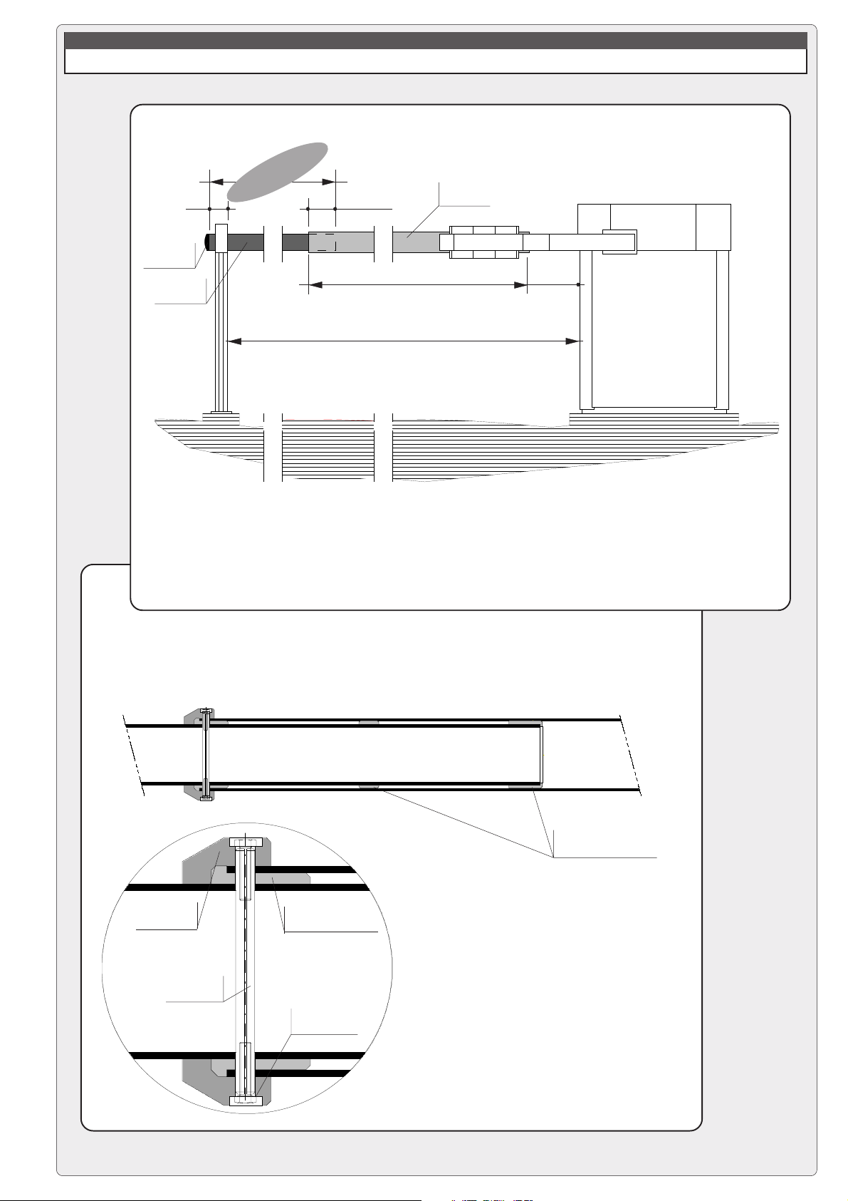
DESCRIPTION OF ASSEMBLY PROCEDURE
1 - ASSEMBLY OF FIXED STRUCTURES, MARKING
a) determine the desired positions
for the housing as well as for the
fixed support for the barrier bar;
mark the longitudinal and
transverse axes of the barrier.
axis of support
for barrier bar
120 x 120
b) detach the mounting base
from the housing and mount
the anchor stays on the base;
apply grease and/or removable
tape to protect the threaded
bolts protruding from the top.
anchor stay
barrier bar rotation
longitudinal axis of barrier
LN = USEFUL NET WIDTH OF PASSAGE = 11850 mm MAX
mounting nut
and washer
UNP 65x42
profile of
mounting base
anchor
screw
6500 mm MIN
axis of
235
865
580
recommended
area for cable exit
- pag. - pag.
- pag.
- pag. - pag.
44
- english - - english -
4
- english -
- english - - english -
44
profile of cement base
c) Sink everything into the
relative cement bases. Be
sure that the mounting base is
perfectly level, and that the
electrical cables for the unit
protrude in the area indicated.
Page 5
END CAP
REAR TUBE
150
DESCRIPTION OF ASSEMBLY PROCEDUREDESCRIPTION OF ASSEMBLY PROCEDURE
DESCRIPTION OF ASSEMBLY PROCEDURE
DESCRIPTION OF ASSEMBLY PROCEDUREDESCRIPTION OF ASSEMBLY PROCEDURE
2 - PRELIMINARY ASSEMBLY OF THE BARRIER BAR
- 5850
N
= L
TP
L
500
depth of
insertion
fixed length 6200 mm
LN
FRONT TUBE
300
REAR TUBE
mounting jaw
a) use the indicated formula to determine length LTP of the rear tube
(Ø100 mm), cut the tube to the correct length and install the end cap.
FRONT TUBE
thrust rings already installed on
Ø100 mm rear tube
thrust ring to be latched
onto the centring pin
centring pin
mounting screw
on mounting jaw
b) assemble the barrier bar by
sliding the rear tube into the front
tube (Ø120 mm, fixed length of 6200
mm) and inserting the centring pin;
next, install and tighten the two
mounting jaws;
- pag. - pag.
- pag.
- pag. - pag.
55
- english - - english -
5
- english -
- english - - english -
55
Page 6

DESCRIPTION OF ASSEMBLY PROCEDURE
3 - INSTALLING THE BARRIER
a) remove the cover of the housing (by lifting) and remove the sides
of the housing (by raising and withdrawing them from below); clean
the cement bases and free the bolts on the anchor stays by
removing the protection tape and nuts;
b) position and mount the
housing on the mounting
base;
c) position and mount the
fixed support for the barrier
bar, and make sure it is in
perfect longitudinal alignment
with the housing;
d) with the aid of a stand and the fixed
support, place the barrier bar at the
approximate height and axis of
operation;
f
e) install the fork and unite the two
e
mounting jaws on the barrier bar, but
do not tighten the bolts;
f) next, mount the barrier bar on the
e
terminal plates of the rotation shaft,
but do not tighten the bolts;
f
- pag. - pag.
- pag.
- pag. - pag.
66
- english - - english -
6
- english -
- english - - english -
66
g) check for misalignment and adjust if necessary; then, firmly tighten
the bar onto the fork and firmly tighten the fork onto the housing.
Page 7

DESCRIPTION OF ASSEMBLY PROCEDURE
4- ASSEMBLING THE COUNTERWEIGHTS; ADJUSTING AND BALANCING THE BARRIER BAR
a) install the release handle,
turn the safety key and rotate
the handle to
release the
gear
motors;
c) balance the bar so
that it stays in position
when it is manually
placed at a 45° angle;
b) insert the counterweight
plates on the support,
alternatively on the
left and right, until
the bar shows
signs of raising.
N.B.: if not all the
counterweight
plates are used,
they must be
fixed with a hose
clamp, to avoid
possible release
during movement.
Hose clamp
d) adjust the vertical
mechanical stop by fixing the
angle of the open barrier bar
so that it does not exceed 90°;
e) adjust the horizontal
mechanical stop when
the barrier bar is in the
lowered position;
- pag. - pag.
- pag.
- pag. - pag.
77
- english - - english -
7
- english -
- english - - english -
77
Page 8

ZL37B CONTROL PANEL
DESCRIPTION & CONTROL LOGIC
MAIN COMPONENTS
1) Transformer
Rallentamento
Velocità
C
O
M
Decele ration
Ralentissement
Geschw.
Abnahme
Deceleración
Speed
Vitesse
Geschw.
Velocidad
1
2) Connectors for power
supply motor
3) Terminal block for motor
connections
4) 2A accessories fuse
5) Amperometric sensitivity
2
"B" "A"
9
adjustment (trimmer
SENS)
6) 3,15A line fuse
10
0
Rall.
Vel.
11
3
4
7) Terminal block for external
connections
8) Jumper for selection of
type of control for button
in 2-7
9) Connectors for connection
to battery charger LB35
12
10) Button for memorizing
code numebers
11) Automatic closing time
5
21 345678910
13
6
74
14
7
adjustment (trimmer TCA)
12) Radio code / automatic
closing signal LED
13) Radiofrequency board
socket (see table pag. 11)
14) "Funcion selection" dipswitch
15) Terminal block for antenna
15
connections
8
This control board is powered by
230V a.c. across terminals L1 and
L2, and is protected by a 3.15A fuse
on the main power line.
Control systems are (24) powered by
low voltage and protected with by a
2A fuse.
The total power consumption of 24V
accessories must not exceed 40 W.
Safety
Photocells can be connected to
obtain:
a)Re-opening during the closing
cycle;
b)Total stop: the movement of the bar
is interrupted, and the automatic
closure cycle is disactivated. Use the
keyboard or the radio transmitter to
resume movement of the bar;
c)Immediate closure (the bar is
lowered automatically after the
vehicle has passed the safety
devices, on the terminals 2-C5 of the
control panel;
- Amperometric safety device: see
NOTE;
Accessories which can be
connected to this unit
- LB35 board, used to power the
automation system using battery
power in case of a power failure. When
the power supply is restored, the
batteries are recharged automatically
(refer to instruction sheet);
- Flashing signal light when bar is in
motion;
- Plug-in radio receiver.
Other functions available
- Automatic closing: The automatic
closing timer is automatically activated
at the end of the opening cycle. The
preset, adjustable automatic closing
time is automatically interrupted by the
activation of any safety system, and
is deactivated after a total stop
command or in case of power failure;
- Obstacle detection: When the motor
is stopped (bar is closed, open or halfopen after an emergency stop
command), the transmitter and the
control pushbutton will be deactivated
if an obstacle is detected by one of the
safety devices (for example, the
photocells);
- “Human presence” operation;
- Flashing light activated before
opening and closing cycle begins;
- Activation of a 24V output signal
during the movement phases and in
the closed position;
- "Slave" operation when two motors
are used in combination (see page
15);
- Function that increases the braking
action on the barrier;
- Selection of command sequence:
-open-close-reverse;
-open only.
Adjustments
- Trimmer TCA = Automatic closing
time: 0" to 120";
- Trimmer SENS = Sensitivity of
amperometric safety system: min/
max.
Important: Shut off the mains power
and disconnect the batteries before
servicing the inside of the unit.
- Fixed operating time of 20 sec.
NOTA
When an obstacle is encountered, the amperometric locking device intervenes as follows:
a) if in the aperture phase, the bar stops;
b) if in the closure phase, the movement of the bar is reversed.
N.B.: In situation (b), if an obstacle is detected three times, the bar stops during aperture, and automatic closure is
disactivated.
Use the keyboard or the radio transmitter to resume movement of the bar.
- pag. - pag.
- pag.
- pag. - pag.
88
- english - - english -
8
- english -
- english - - english -
88
Page 9

QUADRO ELETTRICO ZL37B
M
N
ALLACCIAMENTI & REGOLAZIONI ELETTRONICHE
M
N
F
FA
F
FC
L1
L2
10
11
10
E
FA FC F PT
L1 L2
E+10 - 1 1 1 2 C 1 C 5735
24V A.C. motor
Connection limit switch deceleration opens
Connection limit switch deceleration closes
230V A.C. power
Accessory power: 24V A.C. max. 40W
during movement (e.g. flashing light)
24V output
during movement and in the closed position
DIP 3 OFF
DIP 3 ON
10
5
1
2
2
3
2
7
2
C1
2
C5
24V - 3W max. "barrier open" warning light
STOP button (N.C.)
(see selection functions)
OPEN button (N.O.)
Connector (N.O.) radio and/or pushbutton.
See DIP 2 for command type
Button operation: closure only
Contact (N.C.) for re-opening during closure, if not
used ....
Contact (N.C.) of immediate closure, if not used ....
To install additional pushbutton arrays,
connect:
- the stop buttons in
- the open and warning light in parallel
74
serie
jumper n°8
74
2-C1
E 10 111 2 3 5 7C1 C
dip 8 ON
!"#$%
&'
5
ON
Antenna connection
- pag. - pag.
- pag.
- pag. - pag.
99
- english - - english -
9
- english -
- english - - english -
99
Page 10

ZL37B CONTROL PANEL
SELECTION FUNCTION
0
Vel.
Rall.
1 345678910
2
74
ON OFF
activated deactivated
1
1 = function
automatic closure
1
- deactivated immediate closure (8 ON)
ON OFF
activated deactivated
2
2 = function
"open only"
by radio remote control
2
(when receiver is installed)
ON OFF
deactivated activated
2
2 = funcion
"open-close-inversion"
by radio remote control
2
(when receiver is installed)
1 2 3 4 5 6 7 8 9 10
ON OFF
activated deactivated
5
5 = funcion
flashing light en opening
and closing
ON OFF
activated deactivated
6
6 = function
obstacle detection
(with motor at end of
travel)
ON OFF
activated deactivated
7
7 = function
slave
ON
OFF
5
6
7
ON OFF
activated deactivated
3
movement and in the closed
3 = funcion
24V output during
3
position
ON OFF
deactivated activated
3
3 = function
24V output during
movement
3
ON OFF
activated deactivated
4
4 = funcion
"human presence"
4
ON OFF
deactivated activated
8
8 = function
immediate closure
- connect safety device
across 2-C5;
- deactivate automatic
closure (1 OFF)
8
ON OFF
deactivated activated
9
9 = function
total stop
- connect safety device
across 1-2
ON OFF
activated deactivated
10
10 = function
increase braking action on
barrier bar
10
9
- pag. - pag.
- pag.
- pag. - pag.
1010
10
1010
- english - - english -
- english -
- english - - english -
Page 11

É
0
Vel.
Rall.
74
1 345678910
2
ZL37B CONTROL PANEL
ADJUSTMENTS
SENS.
T.C.A.
REGOLAZION E TRIMMERS
TRIMMERS A DJUSTMENT
R
GLAGE TRIMMERS
EINT ELLU NG TRIM MERS
REGULACIÓN TRIMMERS
Trimmer SENS.
Trimmer T.C.A.
= Adjustment of amperometric sensitivity min./max.
= Adjustment automatic closing time from a minimun of 0 seconds to a maximum of 120
seconds.
A. insertan AF card **.
B. encode transmitter/s.
C. store code in the motherboard.
A
PROGRAMMING THE REMOTE CONTROL
PROCEDURE
AF BOARD INSERTION
Frequency / MHz Radiofrequency board Tra ns m it te r
FM 26.995 AF130
TFM
FM 30.900 AF150
AM 26.995 AF26
TOP
AM 30.900 AF30
AF43S / AF43SM TAM / TOP
AM 433.92
AF43SR ATOM O
The AF board should ALWAYS be inserted when the
power is off because the motherboard only recognises it
when it is powered.
TOP TAM
(**) On AM transmitters operating at 433.92 MHz (TOP and
TAM series), position the jumper connection on circuit card
AF43S as shown on the sheet.
AF
MOTHERBOARD
"AF" BOARD
1111
- pag. - pag.
- english - - english -
- pag.
11
- english -
- pag. - pag.
- english - - english -
1111
Page 12

B
TRANSMITTER ENCODING
TOP
QUARTZ
STANDARD ENCODING PROCEDURE
T262L/M-T264L/M-T2622M
T302L/M-T304L/M-T3022M
1.assign a code (also on file)
2.connect encoding jumper J
3.register code
4.disconnect jumper J
T2622M - T3022M
1° code
P1 P2
P1=CH1
P2=CH2
P1
P2
code
2.
OFF
ON
1.
J
3.
Press P1 or P2 in sequence in order to register
the code; at the tenth pulse, a double beep will
confirm that registration has occurred
4.
J
P1=OFF
J
P2=ON
2° code
P1
P2
J
T264L/M - T304L/M
P1=CH1 - P2=CH2
P3=CH3 - P4=CH4
P1 P2
P3 P4
OFF
ON
P3=CH1
P4=CH2
J
P1 P2
fig. A
J
P1=CH1
P2=CH2
T262L/M - T302L/M
The first encoding operation must be carried out
whilst keeping the jumpers positioned for
channels 1 and 2 as per fig. A; see fig. B for any
subsequent settings on different channels.
fig. B
P1=CH1 - P2=CH3
P1=CH1 - P2=CH4
P1=CH3 - P2=CH2
P1=CH3 - P2=CH4
- pag. - pag.
- pag.
- pag. - pag.
1212
12
1212
- english - - english -
- english -
- english - - english -
Page 13

ATOMO
AT01 - AT02
see instruction sheet inside the pack of AF43SR circuit card
T432M - T312M
P1 P2
P3 P4
P1 P2
1 2 3 4 5 6 7 8 9 10
P1=CH1
P2=CH2
P3=CH3
P4=CH4
1 2 3 4 5 6 7 8 9 10
D
1 2 3 4
C
T434M - T314M
set code only
set the code to dip-switch C and channel to D (P1=CH1
and P2=CH2, default setting)
P1
1 2 3 4 1 2 3 4 1 2 3 41 2 3 4
CH1 CH2 CH3
CH4
P2
1 2 3 4 1 2 3 4 1 2 3 4 1 2 3 4
CH1 CH2 CH3
CH4
T432S
see instructions on pack
TAM
T432
T434
T438
C
TFM
T132
T134
T138
see instruction sheet inside the parck
T152
T154
T158
- pag. - pag.
- pag.
- pag. - pag.
1313
13
1313
- english - - english -
- english -
- english - - english -
Page 14

C
-
While holding down key "CH" signal LED flashing (Fig.1), press the control key on the transmitter: the lights up of
CODE STORAGE
LED sign the code stored (Fig.2).
IMPORTANT: Do not store the code on the circuit card unless the barrier is closed.
N.B.: If you wish to change the code on your transmitters in the future, simply repeat the procedure described
above.
Fig. 1
CH
Flashing LED
Fig. 2
1 345678910
2
4
CH
Lit LED
1 345678910
2
AF radiofrequency board
- pag. - pag.
- pag.
- pag. - pag.
1414
14
1414
- english - - english -
- english -
- english - - english -
4
Page 15

ZL37B CONTROL PANEL
CONNECTIONS FOR 2 COMBINED MOTORS CONTROLLED TOGETHER
1) On one of the two control panels, set
Dip 7 to ON in order to select the motor
controlled externally (slave).
2) Wire the electrical connections only on the terminal board
for the pilot motor in the normal.
C
O
M
0
Rall.
Rallentamento
Deceleration
Ralentissement
Geschw.
Abnahme
Deceleración
"B" "A"
Vel.
74
Velocità
Speed
Vitesse
Geschw.
Velocidad
21 345678910
L1 L2
FA FC F PT
E+10 - 11 1 2 C 1 C 5735
MN
3) Connect the two control panels using the interlock terminals as shown in
the figure.
Pilot motor 1° terminal block
E
+10 - 1 1 1 2 C 1 C 5
7
5
3
INTERBLOCCO
Slave motor 2° terminal block
E
+10 - 1 1 1 2 C 1 C 5
7
5
3
INTERBLOCCO
- pag. - pag.
- pag.
- pag. - pag.
1515
15
1515
- english - - english -
- english -
- english - - english -
Page 16

NOTE
All data checked with the maximum care. However, no liability is accepted for any error or omission.
ASSISTENZA TECNICA
NUMERO VERDE
800 295830
EB
W
www.came.it
E-MAIL
CANCELLI AUTOMATICI
info@came.it
CAME CANCELLI AUTOMATICI S.P.A.
DOSSON DI CASIER (TREVISO)
(+39) 0422 490960 (+39) 0422 490944
SISTEMA QUALITÀ
CERTIFICATO
CAME LOMBARDIA S.R.L.______COLOGNO M. (MI)
(+39) 02 26708293 (+39) 02 25490288
CAME SUD S.R.L. ___________________NAPOLI
(+39) 081 7524455 (+39) 081 7529109
CAME (AMERICA) L.L.C.____________MIAMI ( FL)
(+1) 305 5930227 (+1) 305 5939823
CAME AUTOMATISMOS S.A__________MADRID
(+34) 091 5285009 (+34) 091 4685442
CAME BELGIUM__________________LESSINES
(+32) 068 333014 (+32) 068 338019
CAME FRANCE S.A.____NANTERRE CEDEX (PARIS)
(+33) 01 46130505 (+33) 01 46130500
CAME GMBH________KORNTAL BEI (STUTTGART)
(+49) 07 11839590 (+49) 07 118395925
CAME GMBH____________SEEFELD BEI (BERLIN)
(+49) 03 33988390 (+49) 03 339885508
CAME PL SP.ZO.O______________WARSZAWA
(+48) 022 8699933 (+48) 022 6399933
CAME UNITED KINGDOM LTD___NOTTINGHAM
(+44) 01159 387200 (+44) 01159 382694
 Loading...