

Page 1
MECHANICAL CONTACT RUBBER SAFETY
SENSITIVE EDGE
DF
INSTALLATION MANUAL
Page 2
1 Legend symbols
This symbol indicates sections to read carefully.
This symbol indicates sections regarding safety.
This symbol marks information that is meant specifically for the end user.
2 Destination
2.1 Destination use
DF safety sensitive edges are meant mainly for promiscuous use gate automation systems, for protection against crushing
and trapping hazards. Detection is through contact along the entire length of the edge, including its two ends, thanks to the
ENGLISH
new articulated lever system.
The DF sensitive edge should not be employed for any other purpose than its intended use, as specified above. Instal-
ling the device in a manner other than as indicated in the manual may hamper the device’s safety function.
This manual is intended only for the technical personnel qualified for the installation.
3 Standard followed
The following standards were complied with for this product: EN 12978, UNI EN 954-1, CEI EN 60335-1, UNI EN 12453.
4 Description
4.1 Sensitive edge
The sensitive edge is built in compliance with current safety standards, and it is certified (PR&S no. 04.363) for vertical
application.
The articulated lever mechanism is an exclusive CAME CANCELLI AUTOMATICI S.p.A. patent
The detection device is made up of a rubber profile, two rubber plugs, within which an articulated lever mechanism operates,
joined by a ø 1.3 mm steel cable. The entire device is supported by an aluminium profile.
The sensitive edge is supplied preassembled in the following lengths:
001DF15 - Mechanical contact rubber sensitive edge L = 1,5 m.
001DF17 - Mechanical contact rubber sensitive edge L = 1,7 m.
001DF20 - Mechanical contact rubber sensitive edge L = 2,0 m.
001DF25 - Mechanical contact rubber sensitive edge L = 2,5 m.
The following items in lengths up to 4 or 6 meters may be supplied for other needs:
001CMP - Sensitive rubber and aluminium profile.
001TMF – Set of mechanical contact mechanisms and plugs for sensitive profiles (4 m).
001TMF6 – Set of mechanical contact mechanisms and plugs for sensitive profiles (6 m).
001DFI - Plastic container with cable gland, and control card, which checks for any mechanical damage of electrical connections
between the sensitive edge and the electrical panel.
4.2 Connection specifications
ThePower supply must be SELV or PELV.
Circuits connected to DF and DFI devises must be protected against power surges, as in their contacts’ maximum capacity.
4.3 Technical information
SENSITIVE EDGE
Outputs: C-NC-NO
Contact range: 3A / 24V (Resistive load)
Maximum length: 6 m
Protection level: IP54 (for vertical fastening)
IP44 (for non-vertical fastening)
Category: 2/3 (EN 954-1)
Insulation class:
Maximum detection speed: 12 m/min.
Materials: CCA 48SHA thermoplastic rubber profi le
SEBS 60SHA thermoplastic rubber plugs
POM articulated levers
steel cable
Operative temperature:
#
2
#
DFI BOX
Power supply: 12V<24V AC/DC
63 mA (12V/24V) fuse
Outputs: NC
Contact capacity: 3A / 24V (Resistive load)
Inlet: C-NC-NO
Protection level: IP56
Category: 2/3 (EN 954-1)
Insulation class:
Materiale: box made of self-extinguishing techno polymer
insulation
Operative temperature:
#
#
The data and info rmation provided in th is manual are to be c onsidered su sceptib le to chang e at any time with o ut warning, by CAME cancelli automatici S.p.A.
Page 3
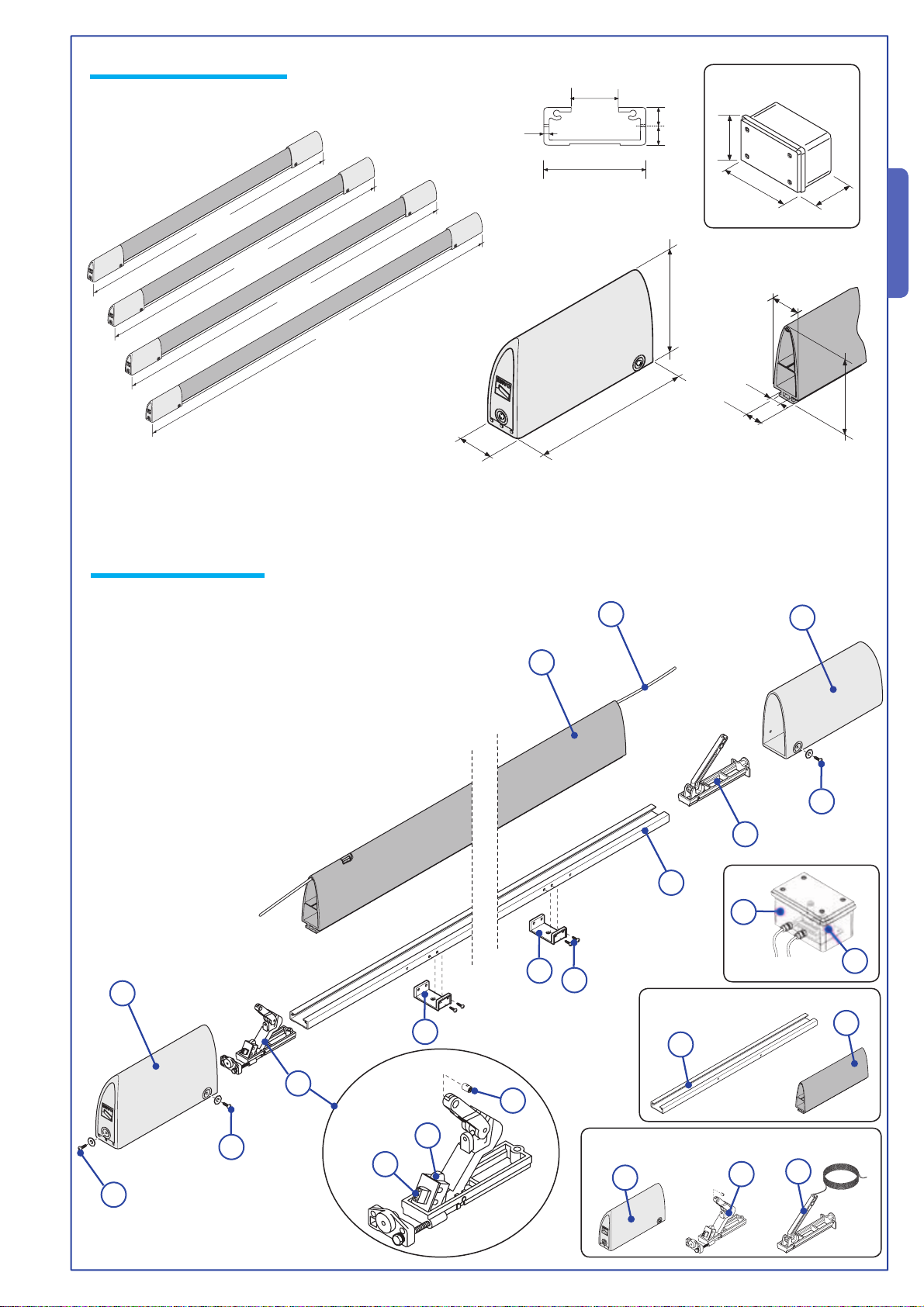
4.4 Size measurements
Measurements in mm
1500
1700
DF15
DF17
DF20
DF25
DFI
ENGLISH
18
2
40
7,57,5
2000
4.5 Parts description
1 - Head plug
2 - Rubber profile
3 - Steel cable
4 - Cable hooking mechanism
5 - Aluminium profile
6 - Mounting bracket
7 - Micro switch holder mechanism
8 - Micro switch
9 - Terminal for electric connection
10 - DFI box
11 - Control board
12 - UNI6954 ø2,9x13 screws
13 - UNI6954 ø3,9x13 screws
14 - Securing terminal
1
2500
40
101
17,5
25
190
46
3
86
1
2
13
4
5
DFI
10
6
12
11
CMP
6
2
5
The data and info rmation provided in th is manual are to be c onsidered su sceptib le to chang e at any time with o ut warning, by CAME cancelli automatici S.p.A.
13
7
14
8
9
TMF
4
1
7
4 m
13
3
Page 4
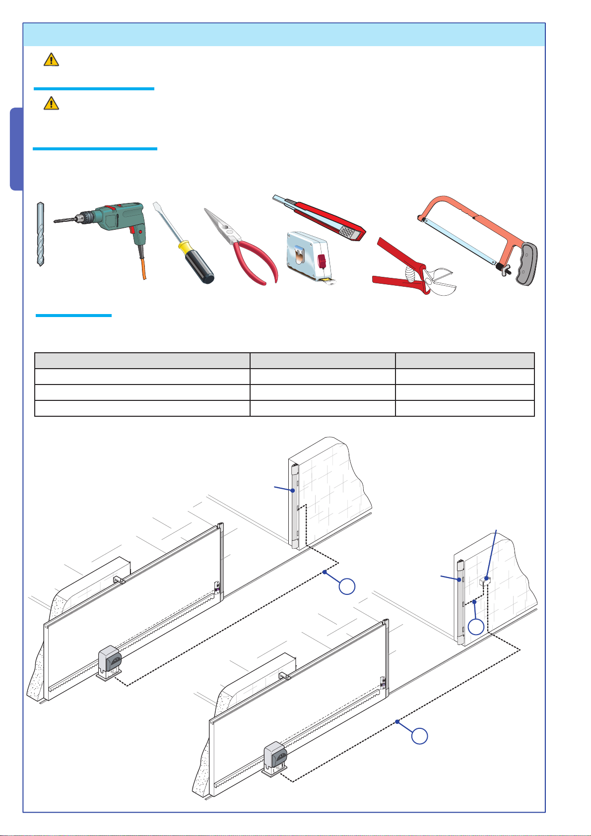
5 Installation
Warning: improper installation may cause serious damage. Follow all installation instructions.
5.1 Preliminary checks
It is necessary to verify that the sensitive edge’s fixing point is on a suitable surface prior to installation.
5.2 Tools and materials
Make sure all tools and materials necessary are within reach to install the edge in maximum safety, according to regulations in
ENGLISH
force. The following figure illustrates the minimum equipment for the installer.
5.3 Cable list
Prepare ducts and tubes suitable for the passage of electrical wiring so as to guarantee protection against mechanical damage. Type of cables recommended:
Connection Cable type and minimum section Maximum length allowed
A - Output contacts C - N.C. FROR (flexible) 2 x 0.5 mm
B - Output contacts C - N.C. - N.O. FROR (flexible) 3 x 0.5 mm
C - Output contacts C - N.C. + Power supply 12-24V FROR (flexible) 4 x 0.5 mm
*A longer cable may be used as long as the section is greater.
DF
2
2
2
A
30 m*
30 m*
30 m*
DFI
DF
B
The data and info rmation provided in th is manual are to be c onsidered su sceptib le to chang e at any time with o ut warning, by CAME cancelli automatici S.p.A.
C
4
Page 5

5.4 Preparation of sensitive edge for varying lengths
150
1) Identify the area to
be protected, nominal
length (LN).
NB.: in vertical
installations, reduce
nominal length (LN)
by 30 mm to prevent
contact with ground.
L N
C
A
M
E
LN - 30
LN
ENGLISH
3) Bore a hole in the
aluminium profile with
a ø 3 mm bit on both
sides to secure plugs,
insert the cable hooking mechanism and tighten the two UNI6955
ø 3.9x13 screws.
L P
30mm
L N
2) Cut the aluminium profile (LP)
and the rubber profile (LG) in the
following manner:
LP = LN - 40 mm;
LG = LN - 285 mm.
L G
1
2
150
4) Insert the rubber profi le in the aluminium
profi le up to the mechanism ledge and
thread the steel cable through the sheath’s
The data and info rmation provided in th is manual are to be c onsidered su sceptib le to chang e at any time with o ut warning, by CAME cancelli automatici S.p.A.
top hole.
5
Page 6

5) Insert the micro switch holder mechanism.
Once inserted, release the lever with slight downward pressure and
tighten the two UNI6955 ø 2.9x13 screws
ENGLISH
1
2
4
2
3
1
3
7) Adjust the cable tension on the mechanism by
means of the adjustment screw and verify that the
NC contact micro switch operates properly
with an Ohmmeter.
Important: for proper adjustment, make
sure the mechanism starts up after 20 mm
max. deformation.
Secure the screw to block the mechanism.
6) Insert the steel cable in the connecting terminal hole; insert
everything in the lever, tension the cable and screw.
Once the cable is adjusted, cut any excess cable.
3
2
1
20 mm
1) Pre-stop = 20 mm
2) Intervention point, response time = 0.2 s
3) Overstop = 45 mm
4) Recovery time at initial point = 2 s
4
The data and info rmation provided in th is manual are to be c onsidered su sceptib le to chang e at any time with o ut warning, by CAME cancelli automatici S.p.A.
1
2
3
6
Page 7

1
3
8) Only for vertical installations: bore a hole with a ø 4 mm bit in the
bottom pre-marked area of the plug to prevent condensate from gathering
within. Insert the plug and secure it with 3 UNI 6954 ø 3.9 x 13 screws
and washers.
ENGLISH
2
5
4
9) Note: if the sensitive edge is positioned vertically, the micro
switch holder mechanism must be set in an elevated position.
Position the three mounting brackets equidistantly, bore a hole
and secure with ø 4 mm screws + custom-made inserts or ø 3.9
mm self-threading self-tapping screws to a metallic surface o its
equivalent. All screws must be the countersunk-head type.
10) Bore a hole in the aluminium profi le with fairlead to allow cable passage and
1
slide cable in for electrical connections. The use of a probe is recommended to
1
facilitate cable sliding through the profi le.
In articles DF15/17/20 the hole is already present.
2
1
2
11) Bore a hole with a ø 0.5 mm bit and
The data and info rmation provided in th is manual are to be c onsidered su sceptib le to chang e at any time with o ut warning, by CAME cancelli automatici S.p.A.
secure with UNI 6954 ø 3.9x13 screws.
O 2,5
7
Page 8

#
./
.#
#
#./.#
6 6 .#./#6
#
5.5 Electrical connections
See paragraph 5.3, Cable List, for choice of cables.
SENSITIVE
EDGE
ENGLISH
CONTROL
PANEL
Electrical connection with control board (DFI) connected between the sensitive
edge mounted on moving wings and control panel.
Electrical connection of sensitive edge to control
panel at terminals for NC safety contacts.
SENSITIVE
EDGE
CONTROL
BOARD
(DFI)
CONTROL
PANEL
The data and info rmation provided in th is manual are to be c onsidered su sceptib le to chang e at any time with o ut warning, by CAME cancelli automatici S.p.A.
After electrical connection operations, insert the head plug and secure it
Attention! Before securing the head plug, make sure the sensitive edge’s
with three UNI6954 ø 3.9x13 screws and washers.
micro switch is in the correct position (see paragraph 5.4 Edge Preparation,
point 7).
8
Page 9

6 Information for End User
6.1 Periodic maintenance
The sensitive edge does not require special maintenance, but it is good practice to periodically (every six months) check
the condition of the rubber profi le and verify the correct operation of the device itself.
Every check must be recorded (in the user’s manual maintenance record book).
Moreover , if needed, clean the device with a vacuum or a cloth moistened with water to remove dirt and debris (do not use solvents
or detergents).
Any changes made to the safety device may cause hazardous situations!
6.2 Problem solving
MALFUNCTION POSSIBLE CAUSES CHECKS AND SOLUTIONS
Sensitive edge does
not react
Sensitive edge operates
with delayed reaction
The automatic system
does not close
• Damaged connections • Prevent use of automatic system as it has become unsafe,
alert technician
• Micro switch not adjusted
• Alert technician
properly
• Sensitive edge under strain
• Damaged connections
• Check if there are objects lying against the edge or if the edge
is warped (call technician)
7 Demolition and disposal
ENGLISH
In its premises, CAME CANCELLI AUTOMATICI S.p.A. implements an Environmental Management System certifi ed in
compliance with the UNI EN ISO 14001 standard to ensure environmental protection.
Please continue our efforts to protect the environment—which CAME considers one of the cardinal elements in the development
of its operational and market strategies—simply by observing brief recommendations as regards disposal:
DISPOSAL OF PACKAGING – The packaging components (cardboard, plastic, etc.) are all classifi able as solid urban waste
products and may be disposed of easily, keeping in mind recycling possibilities.
Prior to disposal, it is always advisable to check specifi c regulations in force in the place of installation.
PLEASE DISPOSE OF PROPERLY!
PRODUCT DISPOSAL – Our products are made up of various types of materials. Most of them (aluminium, plastics, iron,
electrical wires, etc.) may be disposed of in normal garbage collection bins and can be recycled by disposing of in specifi c recyclable
material collection bins and disposal in authorized centres. Other components (electrical boards, remote control batteries, etc.),
however , may contain polluting substances. They should therefore be removed and given to qualifi ed service companies for proper
disposal.
Prior to disposal, it is always advisable to check specifi c regulations in force in the place of disposal.
PLEASE DISPOSE OF PROPERLY!
8 Manufacturer’s warranty
MANUFACTURER’S DECLARATION OF CONFORMITY
CAME Cancelli Automatici S.p.A.
via Martiri della Libertà, 15
31030 Dosson di Casier - Treviso - ITALY
tel (+39) 0422 4940 - fax (+39) 0422 4941
internet: www.came.it - e-mail: info@came.it
Declares under its own responsibility that the equipments for automatic garage doors and
gates listed below:
…protects you from the risk of being crushed or hit by the gate, rated EN 954-1, category 2/3
in compliance with Standard EN 13241-1 concerning EEC 89/106 Building Materials.
The data and info rmation provided in th is manual are to be c onsidered su sceptib le to chang e at any time with o ut warning, by CAME cancelli automatici S.p.A.
… comply with the National Law related to the following European Directives and to the
applicable parts of the following Standards.
98/37/CE - 98/79/CE M
98/336/CEE - 92/31/CEE E
73/23/CEE - 93/68/CE LOW VOLTAGE DIRECTIVE
89/106/CEE CONSTRUCTION PRODUCTS DIRECTIVE
EN 13241-1 EN 12635
EN 12978 EN 60204-1
EN 954-1 EN 61000-6-2
DF15 - DF17 - DF20 - DF25 - CMP - TMF - TMF6 - DFI
SENSITIVE EDGES
ACHINERY DIRECTIVE
LECTROMAGNETIC COMPATIBILITY DIRECTIVE
Pursuant to annex II C of the Machinery Directive 98/37/EC
Do not use the equipment specifi ed here above, before completing the full installation
In full compliance with the Machinery Directive 98/37/EC
IMPORTANT W ARNING!
MANAGING DIRECTOR
Mr. Andrea Menuzzo
Reference code to request a true copy of the original: DDF C EN D002 ver.1.0
9
Page 10

ENGLISH
THIS PAGE LEFT INTENTIONALLY BLANK
10
The data and info rmation provided in th is manual are to be c onsidered su sceptib le to chang e at any time with o ut warning, by CAME cancelli automatici S.p.A.
Page 11

ENGLISH
The data and info rmation provided in th is manual are to be c onsidered su sceptib le to chang e at any time with o ut warning, by CAME cancelli automatici S.p.A.
11
Page 12

CAME UNITED KINGDOM LTD
UNIT 3, ORCHARD BUSINESS PARK
TOWN STREET, SANDIACRE
NOTTINGHAM - NG10 5BP - U.K.
Tel 0044 115 9210430
Fax 0044 115 9210431
Cod. 119RT79 ver. 2.2 07/06 © CAME CANCELLI AUTOMATICI
 Loading...