

Page 1
SET COMPLETE
CLOK
Automazione esterna per cancelli a battente
External automatic opening system for wing gates
Automatisme axtérieur pour portails à battant
Externe Automatik für Flügeltore
Automatizacion exterior para puertas batientes
Documentazione
Tecnica
S25
rev. 0.1
CAME 05/99
©
119DS25
3x1
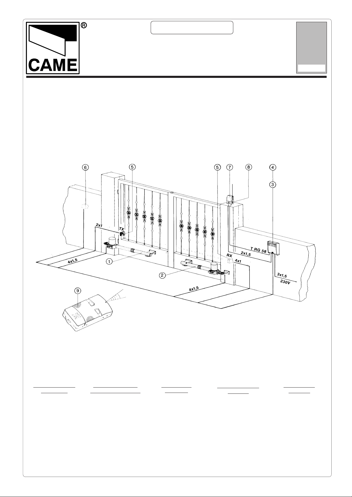
L’apparecchiatura è
completa di:
1) gruppo motore sx
2) N. gruppo motore dx
3) quadro comando
4) ricevitore radio
5) fotocellula di sicurezza
6) Nselettore a chiave
7) lampeggiatore di movimento
8) antenna di ricezione
9) trasmettitori radio
The package includes
the following equipment:
1) Left-hand motor unit
2) Right-hand motor unit
3) Control panel
4) Radio reveicer
5) Safety photocell
6) Key-operated selector
switch
7) Flashing light
8) Receiving antenna
9) Radio transmitters
L’appareillage
comprend:
1) groupe moteur gauche
2) groupe moteur droit
3) armoire de commande
4) récepteur radio
5) photocellule de
sécurité
6) sélecteur à clé
7) clignotant de
mouvement
8) Nantenne de réception
9) émetteurs radio
Das Komplettsystem
beinhaltet:
1) Motoreinheit, links
2) Motoreinheit, rechts
3) Steuergerät
4) Funkempfänger
5) Sicherheits-Photozelle
6) Schlüsselschalter
7) Blinkmeldeleuchte
8) Empfangsantenne
9) Funksender
El equipo está
dotato de:
1) conjunto motor izq.
2) conjunto motor der.
3) cuadro de mandos
4) radiorreceptor
5) fotocélula de
seguridad
6) selèctor con llave
7) lámpara intermitente
8) antena de recepción
9) transmisores
Page 2
Caratteristiche tecniche -
T ecnichal caracteristics
- Contrôles generales -
Allgemeine Prüfungen -
Controles generales
EROTTUDIROTOM
ROTOMRAEG
RUETCUDÉROTOM
ROTOMEBEIRTEG DARGZTUHCS THCIWEG
ROTCUDERROTOM
IDODARG
ENOIZETORP
NOITCETORP
GNITAR
EDÉRGED
NOITCETORP
EDODARG
NOICCETORP
OSEP ENOIZATNEMILA OTNEMIBROSSA AZNETOP
THGIEW YLPPUSREWOP TNERRUC REWOP ELCICYTUD HSUP EMITLEVART ROTICAPAC
SDIOP NOITATNEMILA NOITPROSBA ECNASSIUP
OSEP NOICATNEMILA AICNEBROSBA AICNETOP
3KOLC 45PI gK72 .c.aV032 A5,1 W031 %03
* Ottenuta mediante quadro comando CAME
* Obtained with CAME control panel
* Obtenue au moyen armoire de commande CAME
* Regulierbarer schub erreicht mit Hilfe der CAME Motorsteuerrung
* Empuje regulable obtenido mediante tablero de control CAME
Limiti d'impiego -
Use limits -
_MORTS
GNUGROSREV
Limites d'emploi -
atnaazzehgraL
gniwetagfohtdiW
etierblegülfroT
atreupohcnA
00.2m 008gK
05.2m 006gK
AZNETTIMRETNI
OROVAL
ECNETTIMRETNI
LIAVARTED
EMHANFUAMORTS GNUTSIEL REUADTLAHCSNIE RERABLEGER TIEZFUAL ROTASNEDNOK
AICNETIMRETNI
OJABART
ATNIPS ASROCOPMET EROTASNEDNOC
EÉSSUOP ESRUOCSPMET RUETASNEDNOC
EJUPME
N002÷04*
V erwendungsbereich -
Limites de empleo
atnaoseP
gniwetagfothgieW
liatnavudrueugraL
liatnavudsdioP
thciweglegülfroT
atreuposeP
EDOPMEIT
ODIRROCER
.ces52 Fµ01
RODASNEDNOC
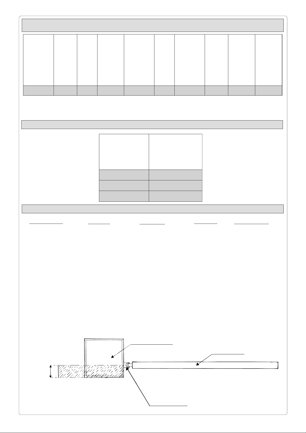
Controlli generali -
Controllare che:
- la struttura del cancello sia adeguatamente
robusta e che i cardini
siano lubrificati;
- la misura C non sia
superiore a 60 mm (50
mm per aperture fino
a 120°), in caso
contrario è necessario
intervenire sul pilastro
in modo da raggiungere tale misura.
General control procedure -
Make sure:
- that the structure of the
gate is sufficiently
strong, and that the
hinges are lubricated;
- that distance C does
not exceed 60 mm (50
mm for opening angles
of up to 120°). If
distance C (Fig. 2)
exceeds these values
the pillar must be
modified so that the
proper distance is
respected.
00.3m 004gK
Contrôles généraux -
Vérifier que:
- la structure du portail
soit suffisamment
robuste et que les
pivots coulissent
correctement;
- la mesire C ne
dépasse pas 60 mm
(50 mm pour des
ouvertures jusqu’à
120°). Dans le cas
contraire, il est
nécessaire d’intervenir sur le pilier de
façon à obtenir cette
mesure.
Pilastro
Pillar
Pilier
Pfosten
Pilar
Allgemeine Prüfungen -
Überprüfen:
- ob die Torstruktur
ausrelchend robust ist
und ob die
Angelzapfen
geschmiert sind;
- ob das Maß C 60 mm
nicht überschreitet (50
mm bei Toröffnung bis
zu 120°), sollte dies
nicht der Fall sein, der
T orpfosten
dementsprechend
anpassen.
Controles generales
Comprobar que:
- la estructura de la
puerta sea
oportunamente recia
y que los goznes
estén lubricados;
- la medida C no
exceda de 60 mm. (50
mm. para aperturas
de hasta 120°), de no
ser así es necesario
actuar sobre el pilar
de modo que alcance
dicha medida.
Anta
Gate wing
Vantail
Torflügel
Hoja
C max.
Cardine
Hinge
Pivot
Angelzapfen
Gozne
2
Page 3
MONTAGGIO -
ASSEMBLY
- MONTAGE -
MONTAGE
- MONTAJE
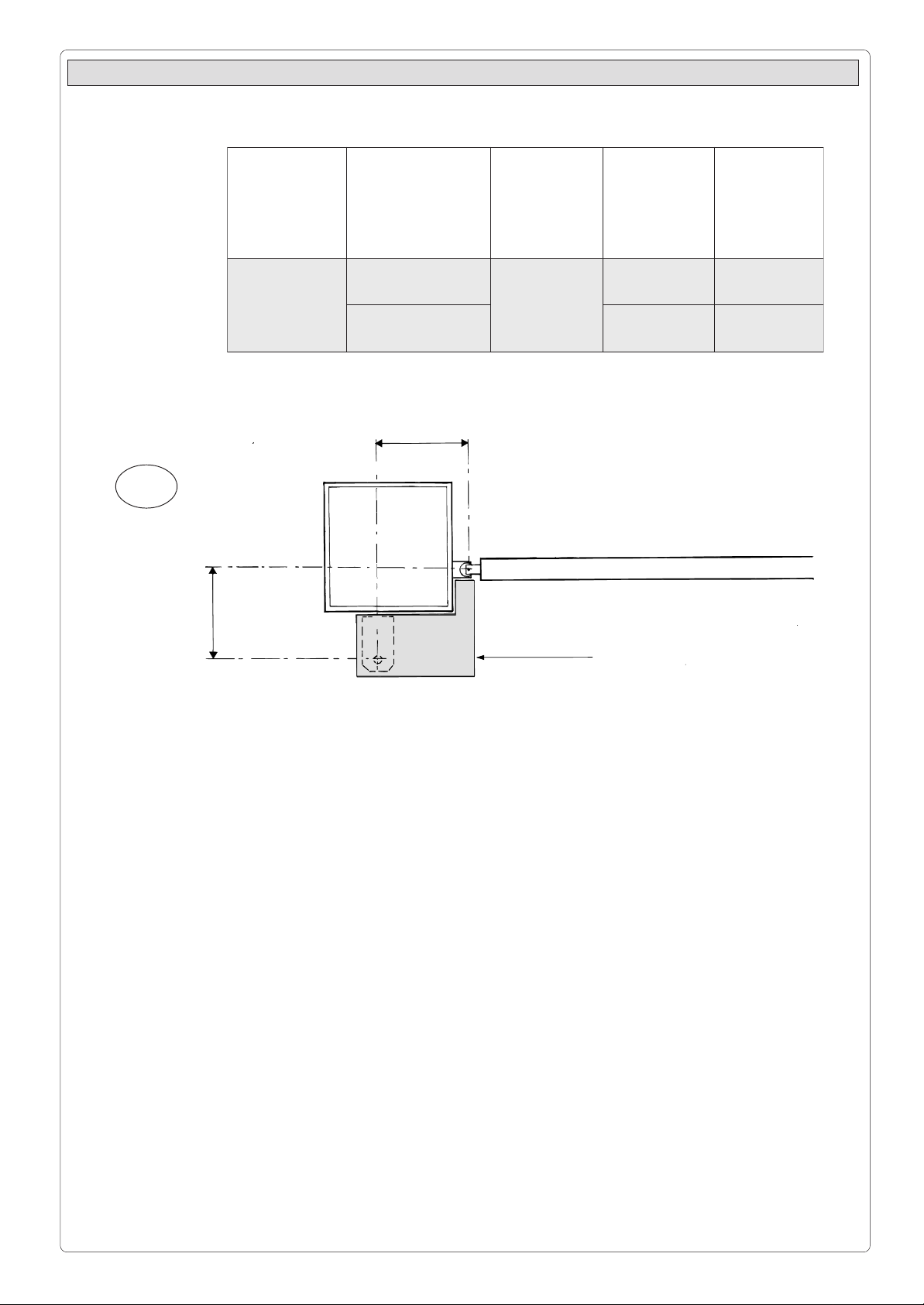
T ab. 1
1
B
OPIT
EPYT
EPYT
EPYT
OPIT
3KOLC
ARUTREPA
ELGNAGNINEPO
ERUTREVUO
GNUNFFÖ
A
mm
B
mm
C
mm
ARUTREPA
°09
031 06
031
°021 011 05
A
Dima
Template
Gabarit
Montageschablone
Plantilla
Fissare la staffa di
coda rispettando le
quote A e B (Tab. 1)
tra il cardine del
cancello e il foro
centrale della staffa
(su cui và fissato il
motoriduttore). Per
agevolare tale operazione, CLOK è dotato
di due DIME in cartone
per aperture a 90° e
120°.
La staffa di coda è
dotata di ulteriori
forature per agevolare
il montaggio del
motoriduttore o per
variare l’angolo di
apertura del cancello.
A seconda dell’installazione e della posizione del cardine del
cancello (rispetto al
pilastro) è possibile
allungare o accorciare
la staffa di coda.
Install the rear bracket
while respecting
distances A and B (T ab .
1) between the hinge on
the gate and the hole in
the centre of the bracket
(which is used to hold
the gear motor). To make
this operation easier, the
CLOCK installation kit
contains two cardboard
templates (for opening
angles of 90° and 120°).
The rear bracket is
equipped with additional
holes to make
installation of the gear
motor easier, or to
change the opening
angle of the gate.
The rear bracket can be
lengthened or shortened
to suit the individual
installation site and the
position of the gate hinge
(with respect to the
pillar).
Fixér l’étrier arrière en
respectant les cotes A
et B (T abl. 1) entre le
gond du portail et le
trou central de l’étrier
(sur lequel sera fixé le
motoréducteur). P our
faciliter cette
opération, CLOCK est
doté de deux
GABARITS en carton
pour des ouvertures à
90° et 120°.
L ’étrier arrière
comprend d’autres
perforations pour
faciliter le montage du
motoréducteur ou
pour modifier l’angle
d’ouverture du portail.
Suivant l’installation et
la position du gond du
portail (par rapport au
pilier), il est possible
d’allonger ou de
raccourcir l’étrier
arrière.
3
Den hinteren Bügel unter
Einhaltung der Maße A
und B (Tab. 1) zwischen
Angelzapfen und der
zentralen Bügelbohrung,
die zur Montage des
Getriebmotors dient,
befestigen. Zur
Montageerleichterung
wird CLOCK mit zwei
MONT AGESCHABLONEN,
für Toröffn ung 90° und
120° geliefert.
Der hintere Bügel ist mit
einer Reihe von
Bohrungen versehen,
die die Montage des
Getriebemotors
erleichtern sowie eine
Änderung des
T oröffnungs winkels
erlauben. Entsprechend
der Angelzapfenposition
am Torpfosten kann der
hintere Bügel verlängert
bzw. verkürzt werden.
Fijar en soporte
trasero respetando las
medidas A o B (T abla
1) entre el gozne de la
puerta y el agujero
central del soporte (en
que se debe fijar el
motorreductor). Para
facilitar esta
operación, CLOCK
está dotado de dos
PLANTILLAS de
cartón para aperturas
de 90° y 120°.
El soporte trasero está
dotado de otros
agujeros para
simplificar el montaje
del motorreductor o
para variar el ángulo
de apertura de la
puerta. En función de
la instalación y de la
posición del gozne de
la puerta metálica (con
relación al pilar) es
posible alargar o
acortar el soporte
trasero.
Page 4

2
Livellare le staffe
Levelli n g th e br ackets
Mettre les étrier de niveau
Bügel ausrichten
Nivelar los soportes
Staffa di coda
Rear brac ket
Etrier arriére
Hinterer Bügel
Soporte trasero
A cancello chiuso,
fissare la staffa di testa
sull’anta del cancello,
in asse orizzontale con
la staffa di coda e
interasse come
indicato (900 mm.)
With the gate closed,
install the front bracket
on the gate wing. The
front bracket, when
installed, must be
aligned along the
horizontal axis of the
rear bracket (see figure)
and the distance
between the centre axes
of the brackets must be
900 mm.
Fixer l’étrier avant sur
le vantail du portail
(vantail en position
fermée), de façon à
obtenir un axe
horizontal avec l’étrier
arrière et avec
l’entraxe comme
indiqué sur le schéma
(900 mm).
Bei geschlossenem Tor ,
den vorderen Bügel auf
gleicher Achse des
hinteren Bügels und mit
einem Achsabstand
gemäß Abbildung (900
mm.) am Torflügel
befestigen.
Staffa di testa
Front bracket
Etrier avant
Vorderer Bügel
Soporte delantero
Estando la puerta
metálica cerrada, fijar
el soporte delantero en
la hoja de la puerta, en
línea horizontal con el
soporte trasero y con
la distancia entre los
ejes indicada (900
mm.).
3
Procedere al montaggio del motoriduttore
alle due staffe.
Install the gear motor on
the two brackets.
N. 2
Réaliser le montage du
motoréducteur sur les
deux étriers.
Getriebemotor auf beide
Bügel montieren.
Montar el
motorreductor en los
dos soportes.
4
Page 5

Verificare che in
qualunque posizione
di apertura del cancello non vi sia contrasto
tra lo stelo del pistone
e l’anta del cancello, in
caso contrario va
allungata la staffa di
testa del minimo
necessario.
Make sure that there is
no interference between
the piston shaft and the
gate wing at any point in
gate travel. If
interference is found,
lengthen the front
bracket to the minimum
length that provides
interference-free
operation.
Quelle que soit la
position d’ouverture
du portail, vérifier qu’il
n’y ait pas de
contraste entre la tige
du piston et le vantail
du portail (dans le cas
contraire, rallonger du
minimum nécessaire
(l’étrier avant).
In allen Toröffnungsstellungen überprüfen,
ob zwischen Kolbenstange und Torflügel
keine Behinderung
auftritt, sollte dies der
Fall sein, den vorderen
Bügel, aufs Minimum
beschränkt, verlängern.
Comprobar que en
cualquier posición de
apertura de la puerta
no haya contraste
entre el vástago del
pistón y la hoja de la
puerta metálica, de no
ser así se debe alargar
el soporte delantero lo
mínimo necesario.
4
Battuta
Doorstop
Dispositif d'arrêt
Anschlag
Tope
Anta
Gate wing
Vantail
Torflügel
Hoja
Battuta
Doorstop
Dispositif d'arrêt
Anschlag
Tope
Prevedere una battuta
di arresto meccanico
(ben fissata al suolo)
in apertura e in chiusura per evitare
l’oltrecorsa anta
motoriduttore.
Install a mechanical
doorstop (which must be
solidly implanted in the
ground) at the open and
closed points of the gate
wing to prevent the gate
wing from exceeding its
maximum travel at the
open and closed
positions.
Prévoir un dispositif
d’arrêt mécanique
(correctement fixé au
sol) dans la phase
d’ouverture et de
fermeture afin d’éviter
une course excessive
vantail/motoréducteur.
5
Einen mechanischen
Endanschlag (gut am
Boden befestigt) in
Öffnungs- und
Schlleßstellung
vorsehen; dies um
T orüberlauf des
Getriebemotors zu
verhindern.
Disponer un tope (bien
fijado en el suelo) para
la apertura y el cierre
para evitar que la
carrera de la hoja
motorreductor
sobrepase el umbral.
Page 6

COLLEGAMENTO ELETTRICO -
ELEKTRISCHE ANSCHLÜSSE
6
Pressacavo
Cable clamp
Serre-cable
Kabelschelle
Sujeta-cables
ELECTRICAL CONNECTONS
- CONEXIONES ELÉCTRICAS
Collegamento filo di terra
Connection point for ground lead
Connexion au câble de terre
Erdleltungsanschluß
Conexión con tierra
Morsettiera
Termina l bl ock
Borne
KlemmenleisteKlemmenleiste
Caja de terminales
Coperchio sede morsettiera
Cover on terminal block seat
Couvercle de la borne
Deckel Klemmenleistenkasten
Tapa pare caja de terminales
- BRANCHEMENTS ÉLECTRIQUES
Fig. 1
Terra
Ground
Terre
Erde
Tierra
- Collegare il
motoriduttore, come
indicato sull’apposita
etichetta fissata sul
motoriduttore stesso
(Fig. 1).
SBLOCCO MOTORIDUTTORE -
7
- Wire the gear motor by
following the wiring
diagram on the label
which is fastened to the
gear motor. (Fig. 1).
- Brancher le
motoréducteur de la
manière indiquée sur
l’étiquette appliquée
sur le motoréducteur
(Fig. 1).
RELEASE GEAR
ANTRIEBSANTRIEGELUNG
Blocco
Locked
Blocage
Gesperrt
Bloqueo
Sblocco
Released
Déblocage
Entsperrt
Desbloqueo
- Den Getriebemotor
gemäß des
Motorschildesanschließen
(Abb. 1).
- OPÉRATION DE DÉBLOCAGE
- DESBLOQUEO MOTORREDUCTOR
90°
- Conectar el
motorreductor como
se indica en la etiqueta
específica incorporada
al motorreductor
(Fig. 1).
Dare il consenso
all’operazione con la
chiave e ruotare di 90°
la manopola di sblocco
ottenendo la corsa
libera delle ante. Per
ripristinarne il funzionamento automatico
riportare la manopola
nella posizione primitiva.
N.B.: L’operazione di
sblocco va comunque
effettuata a motore
fermo.
In case of power failure,
use the key to free the
locking system and
rotate the release handle
90°. To return the system
to automatic operation,
move the release handle
back to its original
position.
ATTENTION: The motor
must be shut down
when the gate wing
release operation is
performed.
Utiliser la clé
permettant de réaliser
cette opération et
tourner le loqueteau
de déblocage de 90°,
ce qui permettra de
déplacer les vantaux
librement. P our rétablir
le fonctionnement
automatique, ramener
le loqueteau dans sa
position d’origine.
N.B.: L’opération de
déblocage doit
toutefois être réalisée
lorsque le moteur est
arrêté.
6
Mittels des Schlüssels,
um den freien Lauf des
T orflügels zu erzielen,
den Entsperrungshebel
um 90° drehen. Zur
Wiederherstellung des
automatischen Betriebs
den Hebel in
Ausgangsstellung
bringen.
ANMERKUNG: Die
Entsperrung muß auf
jeden Fall bei
ausgeschaltetem Motor
vorgenommen werden.
Dar asenso a la
operacion con la llave
y girar 90° la palanca
de desbloqueo, así
logrando la carrera
libre de las hojas.
Para restablecer el
funcionamiento
automático, volver a
colocar la palanca en
la posición antecedente.
NOTA: La operación de
desbloqueo se debe
realizar con el motor
parado.
Page 7

MANUTENZIONE PERIODICA /
PERIODIC MAINTENANCE /
- Lubrificare la vite senza fine e i perni di rotazione;
- Controllare le viti di fissaggio;
- Verificare l'integrita' dei cavi di collegamento.
- Lubricate the worm screw and the rotating pins;
- Ceck the clamps screws;
- Ceck the connection cable's soundness.
- Graisser la vis sans fin et les axes de rotation;
- Contrôler les vis de fixation;
- Contrôler l'intégrité des câbles de branchement.
- Schmieren Sie die Schnecke und die Drehbolzen ab.
- Kontrollieren Sie die Befestigungsschrauben.
- Kontrollieren Sie, ob die Anschlußkabel unversehrt sind.
ENTRETIEN PERIODIQUE /
REGELMÄßIGE WARTUNG
/ MANTENIMIENTO PERIÓDICO
- Lubrique el tornillo sin fin y los pernos de rotación;
- Controle los tornillos de sujeción;
- Controle el estado de los cables de conexión.
7
Page 8
NOTE /
NOTES /
NOTE/
HINWEIS
/ NOTA
CAME S.P.A. ITALIA
VIA MARTIRI DELLA LIBERTÀ, 15
31030 D
OSSON DI CASIER
TREVISO
CAME SUD S.R.L. ITALIA
VIA FERRANTE IMPARATO, 198
CM2 L
OTTO A/7
80146 NAPOLI
CAME FRANCE S.A. FRANCE
7 RUE DES HARAS
92737 NANTERRE CEDEX
PARIS
CAME AUTOMATISMOS S.A. ESPAÑA
C/JUAN DE MARIANA, 17
28045 MADRID
CAME GMBH DEUTSCHLAND
BERGSTRASSE, 17/1
70825 K
ORNTAL
STUTTGART
CAME GMBH DEUTSCHLAND
AKAZIENSTRASSE, 9
16356 S
EEFELD
BERLIN
internet
www.came.it
e-mail
info@came.it
ASSISTENZA TECNICA
NUMERO VERDE
800-295830
N° 12 100 8953
 Loading...