

Page 1

CANCELLI AUTOMATICI
2 x 1 - TX
2 x 1
2 x 1.5
8
6
5
9
1
4
9
10
10
4 x 1 - RX
4 x 1 - RX
11
2 x 1 - TX
3 x 1
2 x 1.5
RG58
4
8
7
6
5
9
1
4
9
10
10
2 x 1 - TX
11
4 x 1 - RX
3
2
3
2
C
A
M
E
12
3 x 1.5 - 110/120V
4 x 1 - RX
SERIE BK241 | BK241 SERIES | SERIE BK241
BK241
Automazioni per cancelli scorrevoli
Automation systems for sliding gates
Automatización para puertas correderas
Documentazione
Tecnica
T68
rev. 0.1
08/2004
©
CAME
CANCELLI
ITALIANO / ENGLISH / ESPAÑOL
AUTOMATICI
119BT68-1
6
Impianto tipo Instalación tipo
1 - Gruppo BK241
2 - Quadro comando incorporato
3 - Ricevitore radio
4 - Alette necorsa
5 - Cremagliera
6 - Selettore a chiave
7 - Lampeggiatore di movimento
8 - Antenna di ricezione
9 - Fotocellule di sicurezza
10 - Colonnina per fotocellula
11 - Fermo anta
12 - Trasmettitore
1 - BK 241unit
2 - Control panel (incorporated)
3 - Radio receiver
4 - Limit switch tabs
5 - Rack
6 - Key-operated selector switch
7 - Flashing light indica-ting door move-
8 - Antenna
9 - Safety photocells
10 - Photocell column
11 - Closure stop
12 - Transmitter
Standard installation
ment
1 - Conjunto BK 241
2 - Cuadro de mando incorporado
3 - Radiorreceptor
4 - Aletas de tope
5 - Cremallera
6 - Selector mediante llave
7 - Lámpara intermitente de movi-
miento
8 - Antena receptora
9 - Fotocélulas de seguridad
10 - Columna para fotocélula
11 - Tope puerta
12 - Transmisor
Page 2

6
.6
3
ITALIANO - ENGLISH - ESPAÑOL
CONTENUTO:
1.0 Descrizione delle parti Pag. 2
2.0 Caratteristiche generali " 4
2.1 Caratteristiche tecniche " 4
2.2 Misure d'ingombro " 4
3.0 Installazione " 4-6
4.0 Descrizione tecnica ZBK241 " 7-8-9
5.0 Scheda base (componenti principali) " 10
5.1 Selezioni funzioni " 11
5.2 Regolazione trimmer " 12
ITALIANO - ENGLISH - ESPAÑOL
5.3 Test di funzionamento fotocellula " 12
5.4 Collegamenti elettrici " 13-14-15
5.5
Programmazione radiocomando
6.0 Collegamenti ne corsa - motore " 19
7.0 Anomalie e soluzioni " 19
8.0 Manutenzioni periodiche " 19
9.0 Note " 19
Dichiarazione del fabbricante " 20
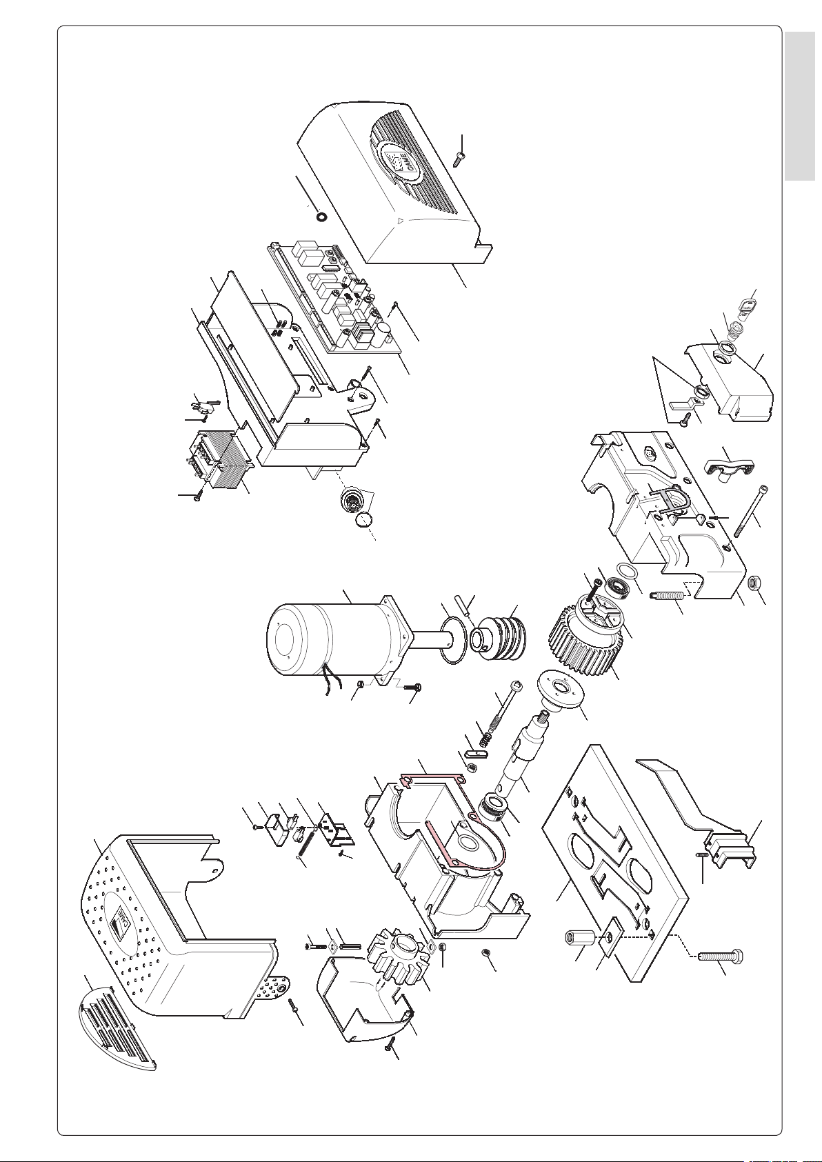
DESCRIZIONE DELLE PARTI / DESCRIPTION OF PARTS / DESCRIPCIÓN DE LOS COMPONENTES
1.0
"
15-16-17-18
CONTENTS:
1.0 Description of parts Page 2
2.0 General features “ 4
2.1 Technical features “ 4
2.2 Size measurements “ 4
3.0 Installation “ 4-6
4.0 Technical description ZBK241 “ 7-8-9
5.0 Motherboard (main components) “ 10
5.1 Function selections “ 11
5.2 Adjustment trimmer “ 12
5.3 Photoelectric cell function test “ 12
5.4 Electrical connections “ 13-14-15
5.5 Remote control programming “ 15-16-17-18
6.0 Motor end-stop connections “ 19
7.0 Anomalies and solutions “ 19
8.0 Periodic maintenance “ 19
9.0 Notes “ 19
Manufacturer’s declaration of conformity “ 20
ÍNDICE:
1.0 Descripción de los Componentes Pág. 2
2.0 Características generales “ 4
2.1 Características técnicas “ 4
2.2 Medidas “ 4
3.0 Instalación “ 4-6
4.0 Descripción técnica ZBK241 “ 7-8-9
5.0 Placa base (componentes principales) “ 10
5.1 Selecciones de las funciones “ 11
5.2 Regulación trimmer “ 12
5.3 Test de funcionamiento fotocélula “ 12
5.4 -Conexiones eléctricas “ 13-14-15
5.5 Programación del radiomando “
6.0 Conexiones n de carrera - motor “ 19
7.0 Desperfectos y soluciones “ 19
8.0 Mantenimiento periódico “ 19
9.0 Notas “ 19
Declaración del fabricante “ 20
15-16-17-18
CODICE
CODE
CÓDIGO
119RIBK001
119RIBK002
119RIBK004
119RIBK005
119RIBK032
119RIBK011
119RIBK023
119RIBK024
119RIBK025
119RIBX002
119RIBY014
119BS310
119RIBK012
119RIY021
119RIY038
3199ZBK-241
DESCRIZIONE
DESCRIPTION
DESCRIPCIÓN
base di fondazione
foundation base
base de cimentación
pignone esterno
external pinion
piñón exterior
albero lento
output shaft
eje lento
cassa riduttore
reducer
caja del reductor
spina elastica
adaptor sleeve
pasador elástico
coperchio motoriduttore
motor gearbox cover
tapa motorreductor
supporto quadro elettrico
electric board support
soporte del cuadro eléctrico
tegolo per supporto quadro elettrico
electrical board support ap
elemento de soporte del cuadro eléctrico
coperchio anteriore Q.E.
front electronic board (Q.E) cover
tapa delantera del cuadro eléctrico
copripignone
pinion cover
cubre piñón
gruppo necorsa
end-stop assembly
grupo n de carrera
motore
motor
motor
portello accesso sblocco
access panel for blocking/release
tapa de acceso al desbloqueo
vite senza ne
worm screw
tornillo sin n
aletta necorsa
limit switch tab
aleta n de carrera
scheda di comando
control board
tarjeta de mando
REF.
6C - 10 - 11 - 12
12C - 13 - 14C - 23 - 24
7C - 8C - 9C - 10C - 13 - 4 - 15 - 16 - 17 - 18 - 19 - 20
2C - 4C - 7 - 7C - 8 - 11C - 21 - 22
12C - 13C -14C -23
19C - 30 - 31
6 - 15C - 16C - 36
37
31C - 32C - 39
15C - 25
16C - 17C - 18C - 26 - 27 - 28 - 29
33
1C - 2 - 3 - 3C - 4 - 5
20C - 32
5C - 9
29C - 30C - 38
2
Page 3
CAM
E
31
30
19c
15c
25
24
12c
11c
23
14c
23
13c
16c
22c
23c
28
26
22
33
26c
35
27c
28c
36
37
29c
15c
16c
30c
32c
21c
20c
32
18
19
20
8c
17
12
11
10
6c
5c
9
16
15
14
13
7
4c
2c
3c
4
5
3
1c
2
1c
8
9c
8c
7c
10c
21
27
17c
29
18c
38
39
6
7c
31c
40
1
6
ITALIANO - ENGLISH - ESPAÑOL
.6
3
Page 4

6
.6
5
170
105
106
255
CAME
360
325
142,5
182,5
15
22 max
(mm)
ITALIANO - ENGLISH - ESPAÑOL
2.0
CARATTERISTICHE GENERALI - GENERAL SPECIFICATIONS - CARACTERÍSTICAS GENERALES
DESCRIZIONE
Progettato e costruito interamente dal-
la CAME, risponde alle vigenti norme
di sicurezza, con grado di protezione
IP54.
Garantito 24 mesi salvo manomissioni.
ITALIANO - ENGLISH - ESPAÑOL
MODELLI
BK241
Modulo pignone m4 portata max
800Kg
DESCRIPTION
Designed and built entirely by CAME, it
complies with current safety standards,
with IP54 protection level.
Guaranteed two-year warranty unless
tampered with by unauthorized persons.
MODELS
BK241
Pinion module m4 max. load 800kg
DESCRIPCIÓN
Diseñado y fabricado completamente
por CAME, responde a las normas de
seguridad vigentes, con grado de protección IP54.
Garantía 24 meses salvo alteraciones.
MODELOS
BK241
Módulo piñón m4 capacidad máx
800Kg
2.1 CARATTERISTICHE TECNICHE - TECHNICAL CHARACTERISTICS - CARACTERISTICAS TECNICAS
MOTORIDUTTORE
GEARMOTOR
MOTORREDUCTOR
BK241 Kg 18 50÷60 Hz
PESO
WEIGHT
PESO
ALIMENTAZIONE
POWER SUPPLY
ALIMENTACION
230V a.c.
ASSORBIMENTO
CURRENT
ABSORBENCIA
(24V)
10 A
POTENZA
POWER
POTENCIA
300 W 50 % 23 Nm 1 / 31 800 N 10,5 m/mi
INTERMITTENZA LAVORO
DUTY CICLE
INTERMITENCIA TRABAJO
COPPIA
MAX TORQUE
PAREJA (MOTOR)
RAPPORTO DI RIDUZIONE
REDUCTION RADIO
RELACION DE REDUCCION
SPINTA
EMPUJE
2.2 MISURE D'INGOMBRO - OVERALL DIMENSIONS - MEDIDAS
PUSH
VELOCITA’ MAX.
MAX. SPEED
VELOCIDAD MAX.
3.0
- Controllare che l'anta sia rigida e che le
ruote di scorrimento siano in buono stato
e adeguatamente ingrassate.
- La guida a terra dovrà essere ben ssata
al suolo, completamente in supercie in
tutta la sua lunghezza e priva di irregolarità
che possano ostacolare il movimento del
cancello.
- I pattini-guida superiori non devono
creare attriti.
- Prevedere una battuta d'arresto in apertura e una in chiusura.
- Preparare il percorso dei cavi elettrici
come da impianto tipo.
INSTALLARE ... - BEFORE INSTALLING ... - ANTES DE INSTALAR EL AUTOMATISMO ...
- The gate must be sufciently rigid and solid;
the wheels on which the gate slide must be in
perfect condition and adequately lubricated.
- The wheel guide must be rmly attached to
the ground, completely exposed, and without
any irregular sections which might hinder the
movement of the gate.
- The upper guide must allow for the correct
amount of play in order to guarantee smooth
and silent movement of the gate.
- Aperture and closure stops must be installed.
- The wiring must be routed as specied by
the control and safety requirements.
- La hoja de la puerta debe estar sucientemiente rigida y compacta; las ruedas de
deslizamiento deben estar perfecta y engrasadas adecuadamente.
- La guia de deslizamiento debe estar bien
jada en el suelo, sobresaliendo a lo largo
de su entera longitud, sin irregularidades
(que podrian obstaculizar el movimiento
de la puerta).
- La guia superior debe tener el justo juego
con la puerta metálica (para garantizar un
movimiento regular y silencioso).
- Disponer un tope para apertura y el
cierre.
- Disponer un conducto para los cables
eléctricos que cumpla con las disposiciones de mando y seguridad.
4
Page 5

50 mm
84 mm
105 mm
(5÷10 mm.)
CAME
1÷1,5 mm
FISSAGGIO BASE MOTORE
- Inserire le viti nella piastra di ancoraggio bloccandole con un dado, ed
estrarre le zanche preformate verso
il basso.
- Predisporre, dimensionandola in base
alle misure del motoriduttore, una piazzola in cemento (si consiglia di farla
sporgere dal terreno di circa 50 mm.)
con annegata la piastra di ancoraggio e
relative zanche sulla quale sara' ssato
il gruppo.
- La base di ssaggio dovra' risultare
perfettamente in bolla, pulita in tutte le
sue estremita', con il letto delle viti
completamente in superce.
N.B.: Dalla stessa dovranno emergere
i tubi essibili per il passaggio dei cavi
di collegamento elettrico.
MOTOR TO BASE ANCHORAGE
- Install the screws in the anchor plate
and fasten them with a nut, then bend the
preformed clamps downwards.
- Construct a cement foundation that is
large enough to accomodate the gear motor
(it is a good idea to protrude 50 mm. from
the ground). When pouring the foundation,
embed the gear motor anchor plate and
the relative clamps in the cement.
- The anchor bolts should be embedded
in the concrete in the positions indicated;
the drive unit is then attached to this bots.
The anchor plate must be perfectly level
and absolutly clean; the bolts threads must
be completly exposed.
N.B.: The exible tubes for the electrical
wiring must be embedded in the base
and protude in the correct position.
FIJACIÓN BASE MOTOR
- Introducir los tornillos en la placa de
anclaje, bloqueándolos con una tuerca, y doblar las palancas preformadas
hacia abajo (bloqueando de esa forma
los tornillos).
- Preparar, dándole las dimensiones
adecuadas en función de las medidas
del motorreductor, una plataforma de
cemento (se aconseja dejarla sobresalir
del suelo aprox. 50 mm.) con la placa de
enclaje embedida y con las correspondientes varillas, que permitrá la jación
del grupo.
- La base de jación debe estar perfectamente nivelada, limpia en todos sus
extremos, con la rosca de los tornillos
totalmente in supercie.
N.B.: De ésta deben sobresilar los tubos
exibles para el paso de los cables para
las conexiones eléctricas.
6
ITALIANO - ENGLISH - ESPAÑOL
POSA DEL GRUPPO
Nella fase preliminare di posa, i piedi-
ni dovranno sporgere di 5-10 mm. per
permettere allineamenti, ssaggio della
cremagliera e regolazioni successive.
L'accoppiamento esatto con la linea
di scorrimento del cancello è ottenibile dal sistema di regolazione integrale
(brevettato) composto da:
- le asole che permettono la regolazione
orizzontale;
- i piedini lettati in acciaio che permettono la regolazione verticale e la
messa in bolla;
- le piastrine e i dadi di ssaggio che
rendono solidale l'aggancio del gruppo
alla base.
Anta cancello
Cremagliera
Rack-limit
Cremallera
Piastra di ancoraggio/Zanche
Fixing plate/ Anchor stays
Placa de jación/arras de jción
Cables
Gate wing
Puerta
Cavo
Cable
UNIT INSTALLATION
During the initial phase of installation, the
feet should protude by 5-10 mm. in order to
allow for alignment, anchorage of the rack
and further adjustments.
Perfect alignment with the guide rail is made
possible by the (paten-ted) built-in regulation
system, wich consists of:
- slots for horizontal adjustment;
- threaded steel feet for vertical adjustment
and levelling;
- plates and bolts for anchorage to the
base.
Struttura ssa
Wall
Estructura ja
Piazzola in cemento
Concrete base
Plataforma de cemento
COLOCACIÓN DEL GRUPO
En la fase previa del emplazamiento,
los pies deben sobresalir 5-10 mm para
consentir la alineación, la jación de
la cremallera y las regulaciones sucesivas.
El acoplamiento exacto con la linea
de deslizamiento de la puerta metálica se obtiene mediante el sistema de
regulación integral (patentado) que
consta de:
- los agujeros ovalados que consienten
la regulación horizontal;
- los pies roscados de acero que
permiten la regulación vertical y la
nivelación;
- las placas y las tuercas de jación
que hacen solidario el enganche del
conjunto con la base.
Regolazione orizzontale e ssaggio
Horizontal adjustment unit and achorage
Regulación horizontal y jación
Regolazione verticale - messa in bolla
Vertical adjustment and unit leveling
Regulación vertical y nivelación
Ingresso cavi
Cable entrances
Entrada cables
.6
5
Page 6

6
.6
7
CAME
CAME
CAME
CAME
A
ITALIANO - ENGLISH - ESPAÑOL
FISSAGGIO CREMAGLIERA
Fissare la cremagliera sul cancello
come segue:
- appoggiare la cremagliera sul pignone
del motoriduttore e far scorrere manualmente il cancello ssando la cremagliera in tutta la sua lunghezza;
- ultimata l'operazione di ssaggio della
cremagliera, regolare i piedini (servendosi di un cacciavite) in modo da
ITALIANO - ENGLISH - ESPAÑOL
ottenere il giusto giuoco tra pignone
e cremagliera 1-1,5 mm.
N.B.: Questo evitera' che il peso del
cancello vada a gravare sul gruppo.
Se la cremagliera é gia' fissata,
procedere direttamente alla regolazione dell'accoppiamento pignone/
cremagliera.
Eseguite tutte le regolazioni, ssare il
gruppo stringendo i dadi di ssaggio.
ATTACHING THE RACK/LIMIT
Attach the rack to the gate as described
below:
- position the rack on the pinion of the gearmotor and slide the gate manually in order
to attach the rack along its entire lenght;
- when the rack is attached to the gate,
adjust the feet using a screwdriver until
the play between the pinion and the rack
is correct (1-1,5 mm.).
N.B. : This play ensures that the weight of
the gate does not rest on the until.
If the rack is already attached, proceed direc-tly to the adjustment of the rack/pinion
coupling.
When the necessary adjustment have been
completed, fasten the unit in position by
tightening the two anchor bolts.
FIJACIÓN DE LA CREMALLERA
Fijar la cremallera en la puerta metálica
como se indica a continuación:
- Apoyar la cremallera en el piñón motorreductor y deslizar manualmente la
puerta metálica jando la cremallera a
lo largo de su entera longitud;
- Finalizadas las operaciones para la
jacion de la cremallera, regular los
pies (por medio de un destornillador)
de modo que se obtenga el justo
juego entre el piñón y la cremallera
(1-1,5 mm).
N.B. Esto hace que el peso de la puerta
metálica no cargue bobre el conjunto.
Si la cremallera ya ha sido jada, hay
que regular el acoplamiento piñón/
cremallera.
Una vez realizados los ajuste, jar el
conjunto cerrando las dos tuercas de
jación.
FISSAGGIO FINECORSA
- Posizionare sulla cremagliera le alette
necorsa che determineranno, con la
loro posizione, la misura della corsa.
Nota: evitare che il cancello vada in
battuta contro il fermo meccanico,
sia in apertura che in chiusura.
SBLOCCO MOTORIDUTTORE
- Per aprire lo sportellino inserire la
chiave A, spingerla e ruotala in senso
orario.
Sbloccare quindi il motoriduttore
applicando la chiave B al perno trilobato
e ruotandola nella direzione indicata.
- Per ribloccare il motoriduttore, avvitare
nella direzione indicata la chiave B no
all'arresto della stessa e senza forzare:
il perno trilobato rientrerà nella sua
sede alla prima manovra.
ATTENZIONE:
l'apertura dello sportellino di sblocco
impedisce il funzionamento del motore.
ATTACHING THE SWITCH TABS
- Position the limit-switch tabs (whose positions determine the limits of gate travel)
on the rack.
Note: do not allow the gate to strike the
mechanical stops in the open or closed
positions.
GEAR RELEASE
- To open the access door, insert the key A,
push down and rotate clockwise.
Then release the ratio motor by using key
B on the threelobed pin and turning it in the
direction indicated.
- To re-lock the reduction gear, turn key B in
the direction indicated until it will move no
further, without forcing it: the three-sided pin
will settle into place at the rst movement.
ATTENTION:
the opening of the unblock panel arrests the
motor.
FIJACIÓN DE LA ALETAS DE TOPE
- Colocar en la cremallera las aletas de
nal de carrera que determinan, con su
posición, la medida de la carrera.
Nota: evitar que la puerta choque contro
el tope mecánico, tanto en la apertura
como en el cierre.
DESBLOQUEO MOTORREDUCTOR
- Para abrir la portezuela introducir la
llave A, empujarla y girarla en sentido
horario.
Desbloqee el motorreductor aplicando
la llave B al perno trilobado y girándo
la manilla en la dirección indicada.
- Para bloquear de nuevo el motorreductor, enrosque la llave B hacia la
dirección indicada hasta el tope y sin
forzar: el perno trilobulado entrará de
nuevo en su alojamiento en la primera
maniobra.
ATENCIÓN:
la apertura de la tapa de desbloqueo, impide
el funcionamiento del motor.
Sblocco
Release
Desbloqueo
Blocco
Engage
Bloqueo
6
Page 7

4.0 DESCRIZIONE TECNICA ZBK241
La scheda comando và alimentata sui morsetti L e N ed è
protetta in ingresso con fusibile 3,15A.
I dispositivi di comando sono a bassa tensione (24V), e sono
protetti con fusibile da 2A. La potenza complessiva degli accessori a 24V, non deve superare i 40W.
Il tempo lavoro è sso a 90”.
SICUREZZA
- Le fotocellule possono essere collegate e predisposte per:
Riapertura: in fase di chiusura (2-C1), le fotocellule rilevando un ostacolo durante la fase di chiusura del cancello, provocano l’inversione di marcia no alla completa apertura;
ATTENZIONE!
Nel caso venga rilevato per due volte consecutive un ostacolo (
sia in fase di apertura che in quella di chiusura), l’ automazione
si blocca e viene attivata la sirena (collegata tra il morsetto 2 e
+AL).
La sirena segnala l’ allarme per 5 minuti, trascorsi i quali, si spegne
automaticamente.
Mediante l’ utilizzo del pulsante di stop nel periodo di funzionamento della sirena, questa viene esclusa.
In qualsiasi caso una volta che l’automatismo ha segnalato un
allarme per ripristinare il normale funzionamento dell’automazione,
occorre premere il pulsante manuale di apertura (o chiusura).
Prima del ripristino manuale è escluso ogni comando radio.
6
ITALIANO - ENGLISH - ESPAÑOL
Richiusura: in fase di apertura (2-C2), le fotocellule rilevando
un ostacolo durante la fase di apertura del cancello, provocano l’inversione di marcia no alla completa chiusura;
Stop parziale: (2-C3), arresto del cancello se in movimento,
con conseguente predisposizione alla chiusura automatica
(se attivato il dip 1 in ON).
FUNZIONI DEI LED
ALIM. verde sempre acceso indica tensione presente
- lampeggia durante il conteggio della chiusura automatica,
- indica fallito test fotocellula;
- lampeggia quando si apre un contatto di sicurezza N.C.
PROG.
STOP giallo si accende quando si apre il contatto 1-2
rosso
- lampeggia nella prog. codice radio;
C1 giallo si accende quando si apre il contatto 2-C1
C2 giallo si accende quando si apre il contatto 2-C2
C3 giallo si accende quando si apre il contatto 2-C3
- lampeggia quando la scheda entra in allarme
Stop totale: (1-2), arresto del cancello escludendo l’eventuale ciclo di chiusura automatica; per riprendere il movimento
bisogna agire sulla pulsantiera o sul radiocomando.
ALTRE FUNZIONI SELEZIONABILI
Chiusura automatica:
Il temporizzatore di chiusura automatica si autoalimenta a necorsa in apertura. Il tempo pressato regolabile, é comunque
subordinato dall’intervento di eventuali accessori di sicurezza e
si esclude dopo un intervento di «stop» totale o in mancanza di
energia elettrica;
Funzione ad “azione mantenuta”:
Funzionamento del cancello mantenendo premuto il pulsante
(esclude il funzionamento del radiocomando);
Apertura parziale:
Apertura del cancello, viene attivata collegando i morsetti 2-3P
ed è regolabile mediante trimmer AP.PARZ..
Con questa funzione, la chiusura automatica varia nel seguente
modo:
1) DIP n°1 in ON “chiusura automatica attiva”:
Dopo un’ apertura parziale, il tempo di chiusura è di 8”.
2) DIP n°1 in OFF “chiusura automatica”.
Se il trimmer del TCA è regolato al minimo dopo un’ apertura
parziale non parte il conteggio di chiusura automatica.
Se il trimmer del TCA è regolato al massimo dopo un’apertura
parziale, il tempo di chiusura è ssato a 8”.
3) Se durante “l’apertura parziale”, interviene il dispositivo collegato ai morsetti 2-C3, il tempo di chiusura automatica e di 8”.
NOTA: se un contatto di sicurezza N.C. (2-C1, 2-C2, 2-C3, 1-
2) si apre, viene segnalato dal lampeggio del LED di segnalazione (vedi pag. 7 componente 11);
Rilevazione di presenza ostacolo:
A motore fermo (cancello chiuso, aperto o dopo un comando
di stop totale), impedisce qualsiasi movimento se i dispositivi
di sicurezza (es.fotocellule) rilevano un ostacolo.
Funzione del test di sicurezza:
Ad ogni comando di apertura e chiusura delle ante, la centralina verica l’efcienza delle fotocellule.
Sensore amperometrico:
La scheda ZBK241, inoltre, integra e gestisce autonomamente una funzione di sicurezza sensibile agli ostacoli che:
In apertura:
inverte il senso di marcia del cancello.
In chiusura:
inverte il senso di marcia del cancello no alla completa
apertura con conseguente predisposizione alla chiusura automatica (se attivato il dip 1 in ON).
Prelampeggio di 5”:
sia in apertura che in chiusura dell’anta;
ATTENZIONE:
- l’apertura dello sportellino di sblocco impedisce il funzionamento del motore.
- prima di intervenire all’interno dell’apparecchiatura, togliere
la tensione di linea e scollegare le batterie (se inserite).
.6
7
Page 8

6
.6
9
ITALIANO - ENGLISH - ESPAÑOL
4.0 TECHNICAL DESCRIPTION ZBK241
The control board should be powered on the L and N terminals
and it is protected with a 3.15A fuse.
The control devices are low-voltage type (24V) and protected
with a 2A fuse. Total power consumption of the 24V accessories
must not exceed 40 W.
The operating time is set at 90”.
ITALIANO - ENGLISH - ESPAÑOL
SAFETY
- The photoelectric cells can be connected and prepared for:
Reopening: during closure (2-C1), the photoelectric cells detect an obstacle during gate closing and cause movement direction to reverse until reaching fully-open position;
Re-closing: during opening (2-C2), the photoelectric cells detect an obstacle during the gate’s opening phase and cause movement direction to reverse until reaching fully-closed position;
Partial stop: (2-C3), the gate stops if moving, with consequent
readying for automatic closure (if dipswitch 1 is set to ON).
Total stop: (1-2), the gate stops, preventing any automatic
closure cycle; to resume movement, the pushbutton or remote
control must be used.
NOTE: if a safety device N.C (2-C1, 2-C2, 2-C3,1-2) opens, this
is indicated by the ashing LED (see p. 7 component 11);
The siren sounds for 5 minutes, after which it automatically
silences.
You can silence the siren during this time by pressing the stop
pushbutton.
Whenever the automation triggers the alarm, to reset normal
functioning, you must press the manual opening (or closing)
pushbutton.
Before manual reset, all remote control functions are excluded.
OTHER SELECTABLE FUNCTIONS
Automatic closure:
The automatic-close timer self-powers when reaching the
fully-open end-stop. The programmable preset time however
depends on the intervention of any safety accessories system
and is cancelled after a total “stop” or power failure;
“Maintained action” function:
Gate operation, by keeping the pushbutton pressed (excludes
the remote-control function);
Partial opening:
Gate opening is activated by connecting the 2-3P terminals
and is adjustable by the P.OPENING trimmer
With this function, automatic closure can vary in the following
way:
LED FUNCTIONS
ALIM. green a lit LED indicates there is power
- ashes during automatic closure count,
- indicates failure of photoelectric cell test;
PROG. red
C1 yellow switches on when device 2-C1 opens
C2 yellow switches on when device 2-C2 opens
C3 yellow switches on when device 2-C3 opens
STOP yellow switches on when device1-2 opens
- ashes when a safety device opens N.C.
- ashes during radio code programming;
- ashes when the board goes into alarm mode
Obstacle presence detection:
With the motor off (gate closed, open or after a total stop command), if the safety devices (e.g. photoelectric cells) detect an
obstacle, all movement is prevented.
Safety test function:
Each time the open/close command is given to the wings, the
control unit checks for photoelectric cell efciency.
1) DIP SWITCH no.1 ON “automatic closure active”:
After a partial opening, the closure time is 8”.
2) DIP SWITCH no.1 OFF “automatic closure”.
If the ACT (Automatic Closing Time) trimmer is set to the minimum after a partial opening, the automatic closure count does
not start.
If the ACT trimmer is set to the maximum after a partial opening,
the closure time is set to 8”.
3) If during “partial opening”, the device connected to terminals 2-C3 intervenes, the automatic closure time is 8”.
Pre-ashing for 5”:
during both gate opening and closing;
Amperometric sensor:
The ZBK241 board also integrates and independently manages
an object-sensitive safety function, which:
During opening:
reverses the gate’s movement direction
During closing:
reverses the gate’s movement direction until it is fully open; it
then readies it for automatic closure (if dipswitch 1 is set to ON ).
CAUTION!
If an obstacle is detected, twice consecutively (during both opening and closing), the automation stops and the siren is activated (connected between terminal 2 e +AL).
8
CAUTION:
- the small access panel for blocking/release prevents the
motor’s operation.
- before intervening with the equipment, switch off the
mains power and remove the batteries (if inserted).
Page 9

4.0 DESCRIPCIÓN TÉCNICA ZBK241
La tarjeta de mando se alimenta en los bornes L y N y está
protegida en la entrada con un fusible de 3,15A.
Los dispositivos de mando son de baja tensión (24V) y están
protegidos con un fusible de 2A. La potencia total de los accesorios a 24V no debe superar los 40 W.
El tiempo de trabajo está jado en 90”.
SEGURIDAD
- Las fotocélulas pueden estar conectadas y preparadas para:
Reapertura: durante el cierre (2-C1), las fotocélulas detectan un
obstáculo durante el cierre de la puerta y provocan la inversión
de marcha hasta la apertura completa;
¡Atención!
Si se detecta durante dos veces consecutivas un obstáculo (tanto
durante la apertura como durante el cierre), la automatización se
bloquea y se activa la sirena (conectada entre el borne 2 y +AL).
La sirena señala la alarma durante 5 minutos , transcurrido dicho
tiempo, se apaga automáticamente.
La sirena se desconecta utilizando el botón de parada durante el
período de funcionamiento de la misma
De todas maneras, una vez que la automatización ha señalado
una alarma para restablecer el funcionamiento normal de la automatización, hay que presionar el botón manual de apertura (o
cierre).
Antes del rearme manual, queda deshabilitado cualquier mando
por radio.
6
ITALIANO - ENGLISH - ESPAÑOL
Cierre: durante la apertura (2-C2), las fotocélulas detectan un ob-
stáculo durante la apertura de la puerta y provocan la inversión de
marcha hasta el cierre completo;
Parada parcial: (2-C3), parada de la puerta si está en movimiento,
con una preparación consiguiente para el cierre automático (si el dip
1 está colocado en ON).
Parada total: (1-2) parada de la puerta excluyendo el ciclo de
cierre automático; para reanudar el movimiento, utilice el teclado o
el radiomando.
Nota: si un contacto de seguridad N.C. (2-C1, 2-C2, 2-C3, 1-2)
se abre, esto es señalado por el destello del LED de señalización (véase pág. 7 componente 11);
FUNCIONES DE LOS LEDS
ALIM.
PROG.
C1
C2
C3
STOP
amarillo
amarillo
amarillo
amarillo
siempre encendido indica la llegada de tensión
verde
- parpadea durante el conteo del cierre automático,
- indica que el test fotocélula ha fallido,
- parpadea cuando se abre un contacto de seguridad N.C.
rojo
- parpadea en la prog. del código radio;
- parpadea cuando se produce una alarma relativa a la tarjeta
se enciende cuando se abre el contacto 2-C1
se enciende cuando se abre el contacto 2-C2
se enciende cuando se abre el contacto 2-C3
se enciende cuando se abre el contacto 1-2
OTRAS FUNCIONES SELECCIONABLES
Cierre automático:
El temporizador de cierre automático se alimenta automáticamente
en el nal de carrera de apertura. El tiempo predeterminado regulable depende del accionamiento de los accesorios de seguridad
y se desactiva después de un accionamiento de “parada” total o
ante el fallo de la alimentación eléctrica;
Función con “accionamiento continuo”:
Funcionamiento de la puerta manteniendo presionado el botón
(deshabilita el funcionamiento del radiomando);
Apertura parcial:
Apertura de la puerta, se activa conectando los bornes 2-3P y se
regula mediante el trimmer AP.PARC.
Con esta función, el cierre automático varía de la siguiente manera:
1) DIP n°1 en ON “cierre automático activo”:
Después de una apertura parcial, el tiempo de cierre es de 8”.
2) DIP n°1 en OFF “cierre automático”.
Si el trimmer del TCA se regula al mínimo, después de una apertura
parcial no comienza el conteo de cierre automático.
Si el trimmer del TCA se regula al máximo, después de una apertura parcial el tiempo de cierre está jado en 8”.
3) Si durante “la apertura parcial”, interviene el dispositivo conectado a los bornes 2-C3, el tiempo de cierre automático es de 8”.
Detección de presencia de obstáculo:
Con el motor detenido (puerta cerrada, abierta o después de
un mando de parada total), impide cualquier movimiento si
los dispositivos de seguridad (por. ej. fotocélulas) detectan un
obstáculo.
Función del test de seguridad:
Cada vez que se acciona la apertura o cierre de las puertas, la
central comprueba la eciencia de las fotocélulas.
Sensor amperimétrico:
La tarjeta ZBK241, también integra y controla automáticamente
una función de seguridad sensible a los obstáculos que:
Durante la apertura:
invierte la dirección de marcha de la puerta.
Durante el cierre:
invierte la dirección de marcha de la puerta hasta la apertura
completa con una preparación consiguiente para el cierre automático (si el dip 1 está colocado en ON).
Predestello de 5”:
tanto durante la apertura como durante el cierre de la puerta;
ATENCIÓN:
- la apertura de la tapa del desbloqueo impide el funcionamiento
del motor.
- antes de trabajar en el interior del equipo, corte la tensión de
línea y desconecte las baterías (en su caso).
.6
9
Page 10

6
.6
11
G Ps
L2T
L1T
0 0 0 0 0 1Ref.Des.
00000
1 2 3 4 5 6 7 8
000001 2
000001 2
0V 12V 24V
2
1 3 4 5 6 7 8 9 1
0
ON
FAFC
FA FC F
FC
FA
F
M
N
1 2 3 4 5 6 7 8 9 10 11 12 03 04 05 06 07 V1 V2 V3 V4 V5
+ SENS.-
+ T.A.C.-
+ T.P.A.-
LINE FUSE 3A
120V =3A
230V=3,15A
PROGRAM.
ZBK241
CH2CH1
MOTOR
FUSE 10A
ACCESSORIES
FUSE 2A
CONTROL BOARD
FUSE 630mA
AF
CONTROL BOARD
ALIM. PROG. STOPC2C1 C3
CAME
R20
G Ps
L N
10 11 E1
TS
1
3
4
7
C3
C2
C1
2
53P2
B1
B2
+AL
-BATT+
G Ps
0V 12V 24V
TO BATTERY CHARGER
G Ps
0 12 24
FROM BATTERY CHARGER
G Ps
0
17 R
24
V
0
230
230 VA
120 V
C E
+BATT-
ZBK241
ITALIANO - ENGLISH - ESPAÑOL
5.0 SCHEDA BASE - MOTHERBOARD - TARJETA BASE
COMPONENTI PRINCIPALI
1 Morsettiere di collegamento
2 Morsetti di collegamento, carica
batteria e batterie
3 Fusibile accessori 2A
4 Fusibile 3,15A di linea
ITALIANO - ENGLISH - ESPAÑOL
5 Fusibile motore 10A
6
Fusibile di scheda elettronica 630 mA
7 Innesto scheda radiofrequenza AF
(vedi 5.5)
8 Pulsanti memorizzazione codice
radio
9 Dip-switch "selezione funzioni"
10 Trimmer AP.PARZ.: regolazione
apertura parziale
11 Trimmer TCA: regolazione tempo di
chiusura automatica
12 Trimmer SENS.:regolazione della
sensibilità amperometrica
13 LED di segnalazione.
ATTENZIONE!
Prima di ogni operazione di connessione
o sconnessione delle schede, togliere la
tensione di linea all’impianto.
MAIN COMPONENTS
1 Connecting terminal board
2 Connecting terminals, battery charger
and batteries
3 2A ttings fuse
4 3.15A line fuse
5 10A motor fuse
6 630 mA electronic board fuse
7 HF(High Frequency)-card connector
(see 5.5)
8 Code memory buttons
9 “Functions selection” dip switch
10 PARTIAL OPENING Trimmer: partial
opening adjustment
11 ACT Trimmer: automatic closure time
adjustment
12 SENS Trimmer: amperometric-sensiti-
vity adjustment
13 Fashing LED
Caution!
Before doing any connection or disconnection work on the board, the system must be
disconnected from the power supply.
COMPONENTES PRINCIPALES
1 Regletas de conexión
2 Bornes de conexión, cargador de
batería y baterías
3 Fusible accesorios 2A
4 Fusible de línea 3,15A
5 Fusible motor 10A
6
Fusible de la tarjeta electrónica 630 mA
7 Conector tarjeta radiofrecuencia
AF (véase 5.5)
8 Botones de memorización del
código radio
9 Dip-switch “selección funciones”
10 Trimmer AP.PARC.: regulación
apertura parcial
11 Trimmer TCA: regulación del
tiempo de cierre automático
12 Trimmer SENS.:regulación de la
sensibilidad amperimétrica
13 LED de señalización.
Atencion!
Antes de cualquier operación de conexión
o desconexión de las tarjetas hay que
quitar la tensión de línea a la instalación.
630 MA 250V fusibile di scheda
elettronica
2A 250V fusibile accessori
3,15A 250V fusibile linea
10A 250V fusibile motore
630 MA 250V electronic board fuse
2A 250V fuse ttings
3.15A 250V line fuse
10A 250V motor fuse
630 MA 250 V Fusible de la tarjeta
electrónica
2A 250V fusible accesorios
3,15A fusible de línea
10A 250V fusible motor
ATTENZIONE!
Nel caso di sostituzioni
utilizzare fusibili dello
stesso tipo.
CAUTION!
For any replacements, use the
same type of amp.
¡ATENCIÓN!
Para las sustituciones utilice
fusibles del mismo tipo.
1
4
2
3
N
L
Alimentazione
Power
Alimentación
nero/black/negro
bianco/white/blanco
6
viola/violet/morado
rosso/red/rojo
marrone/brown/marrón
2
5
12
13
1
7
8
9
10
11
230V a.c.
50/60 Hz
10
Page 11

G
Ps
L2T
L1T
0 0 0 0 0 1
Ref.Des.
00000
1 2 3 4 5 6 7 8
000001 2
000001 2
0V 12V 24V
2
1 3 4 5 6 7 8 9 10
ON
FA
FC
FA FC F
FC
FA
F
M
N
1 2 3 4 5 6 7 8 9 10 11 12 03 04 05
06 07 V1 V2 V3 V4 V5
+ SENS.-
+ T.A.C.-
+ T.P.A.-
LINE FUSE 3A
120V =3A
230V=3,15A
PROGRAM.
ZBK241
CH2
CH1
MOTOR
FUSE 10A
ACCESSORIES
FUSE 2A
CONTROL BOARD
FUSE 630mA
AF
CONTROL BOARD
ALIM.
PROG.
STOP
C2
C1
C3
CAME
R20
G
Ps
L N
10 11 E1
TS
1
3
4
7
C3
C2
C1
2
53P2
B1
B2
+AL
-BATT+
G
Ps
0V 12V 24V
TO BATTERY CHARGER
G
Ps
0 12 24
FROM BATTERY CHARGER
G
Ps
+BATT-
5.1
SELEZIONI FUNZIONI / SELECTION OF FUNCTIONS / SELECCIÓN DE LAS FUNCIONES
ON
OFF
DIP-SWITCHES (1-10)
6
ITALIANO - ENGLISH - ESPAÑOL
1 ON Funzione chiusura automatica
attivata;
2 ON Funzione "Apre-stop-chiude-
stop” con pulsante (2-7) e
radiocomando (scheda AF inserita)
attivato;
2 OFF Funzione "Apre-chiude” con
pulsante (2-7) e trasmettitore radio
(scheda AF inserita) attivato;
3 ON Funzione "solo apertura" con
trasmettitore radio(scheda AF
inserita) attivato;
4 ON "Prelampeggio in apertura
e chiusura" attivato; dopo un
comando di apertura o di chiusura,
il lampeggiatore collegato su 10E1, lampeggia per 5 secondi prima
di iniziare la manovra;
5 ON Rilevazione dell'ostacolo
attivato; a motore fermo (porta
chiusa, aperta o dopo un comando
di stop totale), impedisce qualsiasi
movimento se i dispositivi di
sicurezza (es. fotocellule) rilevano
un ostacolo;
6 ON Funzione ad "azione mantenuta"
attivato;funzionamento del
cancello mantenendo premuto
costantemente il pulsante, pulsante
collegato su (2-3) per l’apertura e
(2-4) per la chiusura, esclude la
funzione del radiocomando;
7 OFF Funzione di riapertura in fase
di chiusura (collegare il dispositivo
di sicurezza sui morsetti 2-C1)
attivata; (se non vengono utilizzati
i dispositivi su 2-C1 posizionare il
dip 7 in ON);
8OFF Funzione di richiusura in fase
di apertura (collegare il dispositivo
di sicurezza sui morsetti 2-C2)
attivata; (se non vengono utilizzati
dispositivi su 2-C2, posizionare il
dip 8 in ON);
9OFF Funzione di stop parziale
(collegare il dispositivo di sicurezza
sui morsetti 2-C3) attivato; (se non
vengono utilizzati i dispositivi su
2-C3, posizionare il dip 9 in ON);
10 ON Funzione del test di sicurezza
per la verica dell'efcenza delle
fotocellule attivato;
1 ON
1 ON Automatic closure function acti-
vated;
2 ON “Open-stop-close-stop” function
with pushbutton (2-7) and remote
control (HF card inserted) activated;
2 OFF “Open-close” function with push-
button (2-7) and radio transmitter
(HF card inserted) activated;
3 ON “Opening only” function with radio
transmitter(HF card inserted) activated ;
4 ON “Pre-ashing opening and clo-
sing” activated; after an opening
or closing command, the ashing
lamp connected on 10-E1 ashes
for 5 seconds before the manoeuvre
begins
5 ON Obstacle detectionactivated; with
motor off (bar closed, open or after
a total-stop command), if the safety
devices (e.g. photoelectric cells)
detect an obstacle, all movements
are prevented;
6 ON “Maintained action” function”
activated; bar functioning, keeping
the pushbutton down, pushbutton
connected on (2.-3) for opening and
(2-4) for closing (excludes the remote control function)
7 OFF Re-opening during closure func-
tion activated (connect safety device
on terminals 2-C1) ; (if devices on
2-C1 are not in use set dip-switch 7
to ON);
8OFF Re-closing during opening fun-
ction activated (connect the safety
device on terminals 2-C2) ; (if the
devices on 2-C2 are not in use, set
dip switch 8 to ON)
9OFF Partial stop function activated
(connect the safety device on terminals 2-C3) ; (if the devices on 2-C3
are not in use, set dip switch 9 to
ON)
10 ON Safety test function for checking
the efciency of the photoelectric
cells activated;
Función cierre automático activa;
2 ON Función “abrir-parada -cerrar-pa-
rada” con botón (2-7) y radiomando
(tarjeta AF conectada) activa;
2 OFF Función “abrir- cerrar” con botón
(2-7) y transmisor radio (tarjeta AF
conectada) activa;
3 ON Función “sólo abrir” con
transmisor radio (tarjeta AF
conectada) activa;
4 ON “Predestello durante apertura
y cierre” activa; después de un
mando de apertura o de cierre,
la luz intermitente, conectada en
10-E1, destella durante 5 segundos
antes de comenzar la maniobra
5 ON Detección de obstáculos activa;
con el motor detenido (puerta
cerrada, abierta o después de
un mando de parada total),
impide cualquier movimiento si
los dispositivos de seguridad
(por. ej. fotocélulas) detectan un
obstáculo;
6 ON Función de “accionamiento
continuo” activa; funcionamiento
de la cancela manteniendo
apretado constantemente el
botón, botón conectado en (2-3)
para la apertura y (2-4) para el
cierre, desconecta la función del
radiomando;
7 OFF Función de reapertura durante
el cierre (conecte los dispositivos
de seguridad en los bornes 2C1) activa; (si no se utilizan los
dispositivos en 2-C1, coloque el
dip 7 en ON);
8 OFF Función de cierre durante la
apertura (conecte los dispositivos
de seguridad en los bornes 2C2) activa; (si no se utilizan los
dispositivos en 2-C2, coloque el
dip 8 en ON);
9 OFF Función de parada parcial
(conecte los dispositivos de
seguridad en los bornes 2-C3)
activa; (si no se utilizan los
dispositivos en 2-C3, coloque el
dip 9 en ON);
10 ON Función del test de seguridad
para el control del funcionamiento
de las fotocélulas activa;
.6
11
Page 12
6
.6
13
2
1 3 4 5 6 7 8 9 10
ON
FA
FC
FA FC F
FC
FA
F
M
N
1 2 3 4 5 6 7 8 9 10 11 12 03 04 05
06 07 V1 V2 V3 V4 V5
+ SENS.-
+ T.A.C.-
+ T.P.A.-
PROGRAM.
ZBK241
CH2
CH1
AF
CONTROL BOARD
ALIM.
PROG.
STOP
C2
C1
C3
CAME
10 11 E1
TS
1
3
4
7
C3
C2
C1
2
53P2
B1
B2
+AL
SENS.
+ T.C.A. -
120
sec.
1
sec.
+ AP. PARZ.-
30
sec.
1
sec.
10 11 E6 E7 TS 1 2 3 3P
FUSIBILE 200mA
TX
2
TX 2
10 2 TX
C
-
+
-
NC
+
-
N.O.
N.C.
C.
10 11 E6 E7 TS 1 2 3 3P
+
-
+
-
( DOC )
( DIR )
ITALIANO - ENGLISH - ESPAÑOL
5.2
REGOLAZIONE TRIMERS / TRIMMER ADJUSTMENT / REGULACIÓN DE LOS TRIMERS
ITALIANO - ENGLISH - ESPAÑOL
-Trimmer TCA = Tempo chiusura
automatica: da 1" a 120";
- Trimmer SENS = Sensibilità del sensore
amperometrico;
- Trimmer AP.PARZ. = Apertura parziale:
da 1" a 30".
-TCA Trimmer = automatic closing time
min 1 sec max. 120 sec.;
-SENS. Trimmer = Amperometric device
sensitivity (min. / max.)
-Trimmer AP.PARZ. = Partial opening:
1" to 30";
-Trimmer T.C.A. = Tiempo cierre
automático mín. 1”, máx. 120”
-Trimmer SENS. = Sensibilidad del
dispositivo amperimétrico (mín. /
máx.)
-Trimmer AP.PARZ. = Apertura parcial:
de 1" a 30";
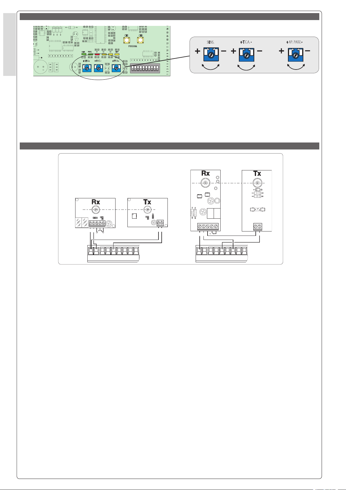
TEST FUNZIONAMENTO FOTOCELLULE / PHOTOCELL FUNCTION TEST / TEST FUNCIONAMIENTO FOTOCELULAS
5.3
FIG. 1
Consente alla centralina di vericare
l'efcenza dei dispositivi di sicurezza
(fotocellule) dopo ogni comando di
apertura o di chiusura. Un eventuale
anomalia delle fotocellule viene
identicata con un lampeggio del led
sul quadro comando, di conseguenza
annulla qualsiasi comando dal trasmettitore o dal pulsante.
Collegamento elettrico per il funzionamento del test di sicurezza:
- I trasmettitori e i ricevitori delle fotocellule devono essere collegati come
illustrati nelle g.1.
- selezionare il dip 10 in ON per attivare il funzionamento del test.
IMPORTANTE: Quando si esegue la
funzione test di sicurezza, i contatti
2-C1, 2-C2 e 2-C3
cortocircuitati ma esclusi tramite dip
7, 8 e 9.
12
, non devono essere
The control unit will now check the safety
system (photocells) every time an opening
or closing command is given. If a photocell
malfunctions, a LED will ash on the control
panel, and the radio transmitter and the
control pushbutton will be deactivated.
Electrical connections required for safety
test function.
Photocell lamps and sensors must be
connected as follows:
- The photoelectric cell transmitters and
receivers must be connected as shown
in g.1.
- set dip switch 10 to ON to activate the
function test.
IMPORTANT: When performing the safety
test function, contacts 2-C1, 2-C2 and 2-C3
must not be short-circuited but excluded
via dip switches 7, 8 and 9.
Permite a la central comprobar la eciencia en los dispositivos de seguridad
(fotocélulas) después de cada comando de apertura y cierre. Una posible
anomalía de las fotocélulas se indica
a través de una luz parpadeante del
LED en el cuadro de mando y, por lo
tanto, se anula cualquier función del
transmisor y de la tecla.
Conexión eléctrica para el funcionamiento de las pruebas de seguridad.
Los transmisores y los receptores de
las fotocélulas deben estar conectados
de la siguiente manera:
- Los transmisores y receptores de las
fotocélulas deben estar conectados
como muestra la g. 1.
- Coloque el dip 10 en ON para activar
el funcionamiento del test.
IMPORTANTE: Cuando se ejecuta la función de test de seguridad, los contactos
2-C1, 2-C2 y 2-C3, no deben cortocircuitearse, sino que deben deshabilitarse
con los dips 7, 8 y 9.
Page 13
G Ps
L2T
L1T
0 0 0 0 0 1Ref.Des.
00000
1 2 3 4 5 6 7 8
000001 2
000001 2
0V 12V 24V
FAFC
FA FC F
FC
FA
F
M
N
G Ps
L N
10 11 E1
TS
1
3
4
7
C3
C2
C1
2
53P2
B1
B2
+AL
-BATT+
CAME
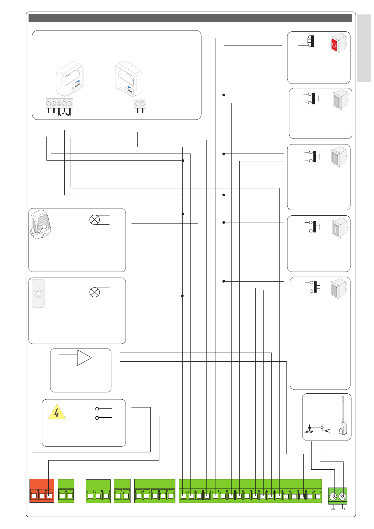
5.4
COLLEGAMENTI ELETTRICI / ELECTRICAL CONNECTIONS / CONEXIONES ELÉCTRICAS
6
Dispositivo di sicurezza (fotocellula, DOC) N.C.
Safety device (photoelectric cell, DOC) N.C.
Dispositivo de seguridad (fotocélula, DOC) N.C.
RX
+ -
n.o.
Uscita in movimento
(es.lampeggiatore 24V-25W)
Output in motion (e.g. 24-25W
ashing light)
Salida en movimento (p.ej.
lámpara intermitente 24-25W)
c
n.c.
24V A.C./D.C.
+ -
10
E1
TX
1
2
Pulsante stop (N.C.)
Pushbutton stop (N.C.)
Pulsador de stop (N.C.)
2
3
Pulsante apre (N.O.)
Pushbutton opens (N.O.)
Pulsador de apertura (N.O.)
2
3P
Pulsante apertura
parziale (N.O.)
Open button (N.O.)
partial aperture
Pulsador de apertura
(N.O.) aperture parcial
2
4
Pulsante chiude (N.O.)
Close button (N.O.)
Pulsador de cierre (N.O.)
ITALIANO - ENGLISH - ESPAÑOL
5
10
Lampada spia (24V-3W) cancello
aperto
(24V-3W) gate-opened signal lamp
Lámpara indicadora (24V-3W)
puerta abierta
2
+AL
Allarme
Alarm
Alarma
L
N
Alimentazione (230 V)
power input (230V)
Alimentación (230 V)
2
7
Contatto radio e/o
pulsante per comando
(vedi dip-switch 2-3
sel.funzioni)( N.O.)
Conta ct radio and/or
button for control (see
dip-switch 2-3 function
selection) (N.O.)
Contacto radio y/o
pulsador para mando
(dip-switch 2-3 seleción
fonción) (N.O.)
Antenna
Antenna
Antena
.6
13
Page 14

6
.6
15
G Ps
L2T
L1T
0 0 0 0 0 1Ref.Des.
00000
1 2 3 4 5 6 7 8
000001 2
000001 2
0V 12V 24V
FAFC
FA FC F
FC
FA
F
M
N
G Ps
L N
10 11 E1
TS
1
3
4
7
C3
C2
C1
2
53P2
B1
B2
+AL
-BATT+
ITALIANO - ENGLISH - ESPAÑOL
ITALIANO - ENGLISH - ESPAÑOL
5.4 COLLEGAMENTI ELETTRICI / ELECTRICAL CONNECTIONS / CONEXIONES ELÉCTRICAS
ZBK241UL
L
N
M
N
10
5
10
E1
10
11
1
2
2
3
Alimentazione (230)
power input (230)
Alimentación (230)
Motore 24V D.C.
motor 24 D.C.
Motor 24 D.C.
Lampada spia (24V-3W) cancello aperto
(24V-3W) gate-opened signal lamp
Lámpara indicadora (24V-3W) puerta abierta
Uscita in movimento (es.lampeggiatore 24V-25W)
Output in motion (e.g. 24-25W ashing light)
Salida en movimento (p.ej. lámpara intermitente 24-25W)
Alimentazione accessori 24V A.C. (max. 40W 1,6A)
24V A.C. powering accessories (max 40W 1,6A)
Alimentación accesoios A.C. 24V (max. 40W 1,6A)
Pulsante stop (N.C.), se non utilizzato cortocircuitarlo
Pushbutton stop (N.C.) If not used, short circuit it
Pulsador de stop (N.C.) Si no se lo utiliza hay que cortocircuitearlo
Pulsante apre (N.O.)
Pushbutton opens (N.O.)
Pulsador de apertura (N.O.)
2
3P
2
4
2
7
2
C1
2
C2
2
C3
Pulsante per apertura parziale (N.O.)
Open button (N.O.) for partial aperture
Pulsador de apertura (N.O.) para aperture parcial
Pulsante chiude (N.O.)
Close button (N.O.)
Pulsador de cierre (N.O.)
Contatto radio e/o pulsante per comando (vedi dip-switch 2-3 sel.funzioni)
Contact radio and/or button for control (see dip-switch 2-3 function selection)
Contacto radio y/o pulsador para mando (dip-switch 2-3 seleción fonción)
Contatto (N.C.) di «riapertura durante la chiusura»
Dispositivo di sicurezza (fotocellule, ecc.)
Contact (N.C.) for «re-aperture during closure»
Safety equipment (photoelectric cells, etc.)
Contacto (N.C.) para la apertura en la fase de cierre.
Equipos de seguridad (fotocélulas, etc.)
Contatto (N.C.) di «richiusura durante la apertura»
"Re-close during opening" contact (N.C.)
Contacto (N.C.) de "cierre durante la apertura"
Contatto (N.C.) "stop parziale"
"Partial stop" contact (N.C.)
Contacto (N.C.) de "parada parcial"
Collegamento antenna
Antenna connection
Conexión antena
2 -
+AL +
14
In caso dell'intervento della funzione "allarme", si attiva per 5' un allarme alimentato a 12V
D.C.(ref. pag. 7)
If the “alarm” function intervenes, an alarm powered at 12V D.C. is activated for 5 “.(ref. page. 7)
Si se activa la función “alarma”, se activa durante 5’ una alarma alimentada en 12V D.C.(ref.
pág. 7)
Page 15

2
1 3 4 5 6 7 8 9 1
0
ON
1 2 3 4 5 6 7 8 9 10 11 12 03 04 05
06 07 V1 V2 V3 V4 V5
+ SENS.-
+ T.A.C.-
+ T.P.A.-
PROGRAM.
ZBK241
CH2
CH1
AF
CONTROL BOARD
ALIM.
PROG.
STOP
C2
C1
C3
CAME
1
3
4
7
C3
C2
C1
2
53P2
B1
B2
+AL
B1
ITALIANO - ENGLISH - ESPAÑOL
B2
Uscita contatto (N.O.) Portata contatto: 5A a 24V D.C.
Contact output (N.O.) Resistive load: 5A 24V D.C.
Salida contacto (N.O.) Carga resistiva: 5A a 24V D.C.
6
F
FA
F
FC
5.5
PROGRAMMAZIONE DEL RADIOCOMANDO /REMOTE CONTROL PROGRAMMING / PROGRAMACIÓN DEL RADIOMANDO
Collegamento (N.C.) necorsa apre
Connection (N.C.) limit switch opens
Conexión (N.C.) n de carrera apertura
Collegamento (N.C.) necorsa chiude
Connection (N.C.) limit switch closes
Conexión (N.C.) n de carrera cierre
A - INSTALLAZIONE DEL RADIOCOMANDO / RADIO CONTROL INSTALLATION / INSTALACIÓN DEL RADIOMANDO
PROCEDURA
A. inserire una scheda AF **.
B. codicare il/i trasmettitore/i.
C. memorizzare la codica sulla scheda
base.
A. insert an AF card **.
B. encode transmitter/s.
C. store code in the motherboard.
PROCEDURE
PROCEDIMIENTO
A. introducir una tarjeta AF **.
B. codicar el/los transmisor/es.
C. memorizar la codicación en la
tarjeta base.
INSERIMENTO SCHEDA AF - AF BOARD INSERTION - MONTAJE DE LA TARJETA AF
SCHEDA BASE
MOTHERBOARD
TARJETA BASE
TOP TAM
SCHEDA "AF"
"AF" BOARD
TARJETA «AF»
(**) Per trasmettitori con frequenza 433.92 AM (serie TOP e serie TAM) bisogna, sulla relativa scheda
AF43S, posizionare il jumper come illustrato.
(**) On AM transmitters operating at 433.92
MHz (TOP and TAM series), position the jumper
connection on circuit card AF43S as shown on
the sheet.
(**) Para transmisores con frecuencia 433.92 AM
(serie TOP y serie TAM) es necesario, en la tarjeta
corespondiente AF43S, colocar el jumper como
se indica
La schedina AF deve essere
inserita OBBLIGATORIAMENTE
in assenza di tensione, perché la
scheda madre la riconosce solo quando viene alimentata
The AF board should ALWAYS be
inserted when the power is off because
the motherboard only recognises it
when it is powered.
La tarjeta AF se debe montar
OBLIGATORIAMENTE en caso de
falta de corriente, porque la tarjeta
madre la reconoce sólo cuando está
alimentada
.6
15
Page 16

6
.6
17
ITALIANO - ENGLISH - ESPAÑOL
B - CODIFICA TRASMETTITORI / TRANSMITTER ENCODING / CODIFICACIÓN TRANSMISORES
TOP QUARZATI - QUARTZ - CUARZO
PROCEDURA COMUNE DI CODIFICA
T262M-T264M-T2622M
T302M-T304M-T3022M
1.segnare un codice (anche per archivio)
2.inserire jumper codica J
ITALIANO - ENGLISH - ESPAÑOL
3.memorizzarlo
4.disinserire jumper J
1.
codice/codice/codice
T2622M - T3022M
1° codice/codice
codice
J
P1=CH1
P2=CH2
STANDARD ENCODING PROCEDURE
T262M-T264M-T2622M
T302M-T304M-T3022M
1.assign a code (also on le)
2.connect encoding jumper J
3.register code
4.disconnect jumper J
3.
premere in sequenza P1 o P2 per registrare il
codice; al decimo impulso un doppio suono
confermerà l'avvenuta registrazione
Press P1 or P2 in sequence in order to register
the code; at the tenth pulse, a double beep will
conrm that registration has occurred
oprimir repetidamente P1 ó P2 para registrar el
código; con el décimo impulso un doble sonido
señalará que el registro se ha efectuado.
PROCEDIMIENTO COMŠN DE CODIFICACIÓN
T262M-T264M-T2622M
T302M-T304M-T3022M
1.marcar un código (también para el archivo)
2.conectar un jumper codicación J
3.registrar el código
4.desconectar jumper J
2.
J
P1=OFF
P2=ON
4.
2° codice/codice//codice
J
T264M - T304M
P1=CH1 - P2=CH2
P3=CH3 - P4=CH4
P3=CH1
P4=CH2
J
g.
A
J
P1=CH1
P2=CH2
J
T262M - T302M
La prima codica deve essere effettuata mantenendo i jumper
posizionati per i canali 1 e 2 come da g. A; per eventuali e successive impostazioni su canali diversi vedi g. B
The rst encoding operation must be carried out whilst keeping
the jumpers positioned for channels 1 and 2 as per g. A; see g.
B for any subsequent settings on different channels.
La primera codicación tiene que efectuarse manteniendo los
jumper conectados para los canales 1 y 2 como se ilustra en
la g. A; para planteamientos posteriores en canales distintos
ver la g. B
g. B
P1=CH1 - P2=CH3
P1=CH1 - P2=CH4
P1=CH3 - P2=CH2
P1=CH3 - P2=CH4
16
Page 17

B - CODIFICA TRASMETTITORI / TRANSMITTER ENCODING / CODIFICACIÓN TRANSMISORES
TOP
T432M - T312M
D
P1=CH1
P1=CH1
P2=CH2
P2=CH2
P3=CH3
P3=CH3
P4=CH4
P4=CH4
D
C
C
impostare il codice sul dip-switch C e il canale su D (P1=CH1 e P2=CH2,
impostazione di default)
set the code to dip-switch C and channel to D (P1=CH1 and P2=CH2,
default setting)
plantear el código en el dip-switch C y el canal en D (P1=CH1 y P2=CH2,
planteamiento por defecto)
P1
P1
CH1 CH2 CH3
CH1 CH2 CH3
P2
P2
CH1 CH2 CH3
CH1 CH2 CH3
T432S / T432SA/T434MAT434M - T314M
impostare solo il codice
set code only
plantear sólo el código
CH4
CH4
CH4
CH4
6
ITALIANO - ENGLISH - ESPAÑOL
C
C
vedi istruzioni su confezione
see instructions on pack
ver instrucciones en el embalaje
B - CODIFICA TRASMETTITORI / TRANSMITTER ENCODING / CODIFICACIÓN TRANSMISORES
ATOMO - TAM - TFM
ATOMO
ATOMO
AT01
AT01
AT02
AT02
AT04
AT04
vedi foglio istruzioni inserito nella confezione
della scheda AF43SR
see instruction sheet inside the pack of
AF43SR circuit card
ver hoja de instrucciones adjunta en el embalaje
de la tarjeta AF43SR
TAM
TAM
T432
T432
T434
T434
T438
T438
vedi foglio istruzioni inserito nella confezione
see instruction sheet inside the pack
ver hoja de instrucciones adjunta en el embalaje
TFM
TFM
T132
T134
T132
T138
T134
T138
T152
T154
T152
T158
T154
T158
.6
17
Page 18

6
.6
19
ITALIANO - ENGLISH - ESPAÑOL
C - MEMORIZZAZIONE CODICE / CODE STORAGE / MEMORIZACIÓN CÓDIGO
-Tenere premuto il tasto "CH1" sulla
scheda base (il led di segnalazione lampeggia), con un tasto del trasmettitore
s'invia il codice, il led rimarrà acceso a
segnalare l'avvenuta memorizzazione
(vedi g.1).
Eseguire la stessa procedura con il tasto
ITALIANO - ENGLISH - ESPAÑOL
"CH2" associandolo con un altro tasto
del trasmettitore (g.2).
CH1 = Canale per comandi diretti ad
una funzione della centralina del motoriduttore (comando "solo apre" / "aprechiude-inversione" oppure "apre-stopchiude-stop", a seconda della selezione
effetuata sui dip-switch 2 e 3).
CH2 = Canale per comandi diretti ad
un dispositivo accessorio collegato
su B1-B2.
N.B.: se in seguito si vuol cambiare
codice, basta ripetere la sequenza
descritta.
-Keep the CH1 key pressed on the base
card (the signal LED will ash), and with a
key on the transmitter the code is sent, the
LED will remain lit to signal the successful
saving of the code (gure 1).
Perform the same procedure with the CH2
key, associating it with another transmitter
key (gure 2).
CH1 = Channel for direct control of one
function performed by the control unit
on the gear motor ("open only" / "openclose-reverse" or "open-stop-close-stop",
depending on the position of dip switches
2 and 3).
CH2 = Channel for direct control of an accessory connected across B1-B2.
N.B. If you wish to change the code on
your transmitters in the future, simply repeat
the procedure described above.
-Mantener oprimida la tecla "CH1" en
la tarjeta base (el led de señalización
parpadea), con una tecla del transmisor
se envía el código, el led permanece
encendido para indicar que el almacenamendo se ha efectuado (g.1).
Efectuar el mismo procedimiento con
la tecla "CH2" asociándola a otra tecla
del transmisor (g.2).
CH1 = Canal para mando directo a una
función de la central del motorreductor
(mando "solo abre" / "abre-cierra-inversión" o "abre-stop-cierra-stop", según
la selección efectuada en los dip-switch
2 y 3).
CH2 = Canal para un mando directo a
un dispositivo accesorio conectado
en B1-B2.
NOTA: Si posteriormente se quisiera
cambiar el código de los propios
transmisores, sólo hay que repetir la
secuencia descrita.
LED di segnalazione
signal LED
LED de señal
Fig./Abb. 1
Scheda radiofrequenza AF
AF radiofrequency board
Tarjeta radiofrecuencia AF
Fig./Abb. 2
18
Page 19

6.0 COLLEGAMENTI FINE CORSA / LIMIT SWITCH CONNECTIONS / CONEXION FINAL DE CARRERA
Gruppo motore-necorsa già collegati per montaggio a sinistra vista
interna.
Per eventuale montaggio a destra:
- invertire FA-FC dei necorsa sulla
morsettiera;
- invertire le fasi M-N del motore sulla
morsettiera.
FCFA
N.C.
F
N.C.
M N
The motor and limit switch unit are wired
at the factory for mounting on the lefthand side of the gate (as seen from the
inside).
If right-hand installation is desired:
- invert limit switch connections FA-FC on
the terminal block;
- invert motor phase connections M-N on
the terminal block.
FA
NC
Grupo motor n de carrera ya conectados para el montaje a la izquierda
vista interior. Para el eventual montaje
a la derecha:
- invertir FA-FC de los nes de carrera
en el cuadro de bornes;
- invertir las fases M-N del motor en el
cuadro de bornes.
FC F
NC
M N
6
ITALIANO - ENGLISH - ESPAÑOL
M
Gruppo necorsa
Limit switch unit
Grupo n de carrera
M
Motore monofase 24V (D.C.)
24V (D.C.) single-phase motor
Motor monofásico de 24V (D.C.)
Gruppo necorsa
Limit switch unit
Grupo n de carrera
Motore monofase 24V (D.C.)
24V (D.C.) single-phase motor
Motor monofásico de 24V (D.C.)
7.0 ANOMALIE E SOLUZIONI / ANOMALIES AND SOLUTIONS / DESPERFECTOS Y SOLUCIONES
IL CANCELLO NON SI MUOVE:
- Controllare la tensione 230V AC sui
morsetti L-N.
- Controllare i fusibili.
- Controllare la tensione 24V sui morsetti 10-11
- Vericare il collegamento del pulsante
di stop; se non previsto ponticellarlo
tra i morsetti 1-2.
- Controllare che lo sportellino accesso
sblocco sia chiuso
IL CANCELLO RIMANE NELLA POSIZIONE DI
APERTURA:
- Chiusura automatica disabilitata,
vedere dip n°1.
- Comando ad "azione mantenuta" attivato, vedere regolazione del dip n°6.
- Controllare tutti i dispositivi di comando, stiano funzionando correttamente.
- Assicurarsi che non ci siano ostruzioni nei dispositivi di sicurezza.
- Assicurarsi che tutti i contatti N.C.
siano disattivati se non utilizzati.
THE GATE DOES NOT MOVE:
- Check the 230V AC power on the terminals L-N.
- Check the fuses.
- Check the 24 V power on terminals
10-11
- Check the stop button connection; if it is
not active, jumper it on terminals 1-2.
- Check that the small access panel for
blocking/release is closed
THE GATE REMAINS IN THE OPEN POSITION:
- Automatic closure disabled, see dip
no.1.
- “Maintained Action” command activated,
see setting of dip no. 6.
- Check all the command devices are
working correctly.
- Ensure that nothing is obstructing the
safety devices.
- Ensure that all the N.C. contacts are
deactivated if not in use.
LA PUERTA NO SE MUEVE:
- Controle la tensión 230V AC en los
bornes L-N.
- Controle los fusibles.
- Controle la tensión 24V AC en los
bornes10-11
- Controle la conexión del botón de parada; si no estuviera previsto, haga un
puente entre los bornes 1-2.
- Controle que la tapa de acceso al
desbloqueo esté cerrada
LA PUERTA QUEDA EN LA POSICIÓN DE
APERTURA:
- Cierre automático deshabilitado,
véase dip n°1.
- Mando de “accionamiento continuo”
activo, véase la regulación del dip n°6.
- Controle que todos los dispositivos
de mando estén funcionando correctamente.
- Controle que no haya obstrucciones
en los dispositivos de seguridad.
- Controle que todos los contactos
N.C. estén desactivados si no se los
utiliza.
8.0 MANUTENZIONI PERIODICHE / PERIODIC MAINTENANCE / MANTENIMIENTO PERIÓDICO
-Vericare la regolazione dell' accoppiamento pignone cremagliera
-Vericare il ssaggio della cremagliera;
-Vericare l'integrità dei cavi di collegamento.
- Check the adjustment of the rack/pinion
coupling
- Ensure the rack is securely positioned;
- Ensure the connecting cables are intact.
-Controle la regulación del acoplamiento piñón-cremallera
-Controle la jación de la cremallera;
-Controle la integridad de los cables
de conexión.
9.0 NOTE / NOTES / NOTAS
.6
19
Page 20

6
Documentazione
Tecnica
T68
rev. 0.1
07/2004
©
CAME
CANCELLI
AUTOMATICI
CANCELLI AUTOMATICI
BK241
SERIE BK241 | BK241 SERIES | SERIE BK241
ITALIANO / ENGLISH / ESPAÑOL
119BT68-1
DICHIARAZIONE DEL FABBRICANTE
Ai sensi dell’Allegato II B della Direttiva Macchine 98/37/CE
Allegata alla documentazione tecnica (l’originale della Dichiarazione è disponibile a richiesta)
I Rappresentanti della
CAME Cancelli Automatici S.p.A.
via Martiri della Libertà, 15
31030Dosson di Casier - Treviso - ITALYtel
(+39) 0422 4940 - fax (+39) 0422 4941
internet: www.came.it - e-mail: info@came.it
Dichiarano sotto la propria responsabilità che i/il prodotto/i denominato/i ...
BK-1200 BK-1800 BK-2200 BKE-1200 BKE-1800 BKE-2200 BK-241
B4353 BRC5 BRC10 BRC15 BRCP BSF
CCT CGIU CGZ CGZ6 CGZS R001
… sono conformi alle disposizioni legislative Nazionali che traspongono le seguenti Direttive
Comunitarie (dove specicatamente applicabili):
DIRETTIVA MACCHINE 98/37/CE
DIRETTIVA BASSA TENSIONE 73/23/CEE - 93/68/CEE
DIRETTIVA COMPATIBILITÅ ELETTROMAGNETICA 89/336/CEE - 92/31/CEE
DIRETTIVA R&TTE 1999/5/CE
Documentazioni tecniche speciche dei prodotti sono disponibili a richiesta!
MANUFACTURER’S DECLARATION
As per Enclosure II B of Machinery Directive 98/37/CE
Enclosed with the technical documentation (the original copy of the Declaration is available on request)
The representatives of
CAME Cancelli Automatici S.p.A.
via Martiri della Libertà, 15
31030 Dosson di Casier - Treviso - ITALY
tel (+39) 0422 4940 - fax (+39) 0422 4941
internet: www.came.it - e-mail: info@came.it
Hereby declare, under their own respons ibility, that the product/s called ...
BK-1200 BK-1800 BK-2200 BKE-1200 BKE-1800 BKE-2200 BK-241
B4353 BRC5 BRC10 BRC15 BRCP BSF
CCT CGIU CGZ CGZ6 CGZS R001
… comply with the Italian National Legal Provisions that transpose the
following Community Directives (where specically applicable):
MACHINERY DIRECTIVE 98/37/CE
LOW VOLTAGE DIRECTIVE 73/23/EEC - 93/68/EEC
LECTROMAGNETIC COMPATIBILITY DIRECTIVE 89/336/EEC - 92/31/EEC
R&TTE DIRECTIVE 1999/5/CE
Inoltre, dichiara che il/i prodotto/i, oggetto della presente dichiarazione, sono costruiti nel
rispetto delle seguenti principali norme armonizzate:
EN 292 PARTE 1ª E 2ª SICUREZZA DEL MACCHINARIO.
EN 12453 CHIUSURE INDUSTRIALI, COMMERCIALI …
EN 12445 CHIUSURE INDUSTRIALI, COMMERCIALI …
EN 60335 - 1 SICUREZZA NEGLI APPARECCHI AD USO DOMESTICO ...
EN 60204 - 1 SICUREZZA DEL MACCHINARIO.
EN 50081 - 1 E 2 COMPATIBILITÅ ELETTROMAGNETICA.
EN 50082 - 1 E 2 COMPATIBILITÅ ELETTROMAGNETICA.
AVVERTENZA IMPORTANTE!
È vietato mettere in servizio il/i prodotto/i, oggetto della presente dichiarazione, prima del
completamento e/o incorporamento, in totale conformità alle disposizioni della Direttiva
Macchine 98/37/CE
RESPONSABILE TECNICO
Also, they furthermore represent and warrant that the product/s that are the subject of the present
Declaration are manufactured in the respect of the following main harmonized provisions:
EN 292 PART 1 AND 2 MACHINERY SAFETY.
EN 12453 INDUSTRIAL, COMMERCIAL AND OTHER CLOSING MECHANISMS.
EN 12445 INDUSTRIAL, COMMERCIAL AND OTHER CLOSING MECHANISMS.
EN 60335 - 1 SAFETY IN APPARATUSES FOR HOME USE.
EN 60204 - 1 MACHINERY SAFETY.
EN 50081 - 1 AND 2 ELECTROMAGNETIC COMPATIBILITY.
EN 50082 - 1 AND 2 ELECTROMAGNETIC COMPATIBILITY.
IMPORTANT CAUTION!
It is forbidden to market/use product/s that are the subject of this declaration before completing and/
or incorporating them in total compliance with the provisions of Machinery Directive 98/37/CE
TECHNICAL MANAGER
Sig. Gianni Michielan
Signatures of the Representatives
Mr. Gianni Michielan
Data della presente dichiarazione 07/12/2001
Firma dei Rappresentanti
PRESIDENTE
Sig. Paolo Menuzzo
Date of the present declaration 07/12/2001
MANAGING DIRECTOR
Mr. Paolo Menuzzo
Specic technical documentation on the products is available on request!
DECLARACION DEL FABRICANTE
De conformidad con el Anexo II B de la Directiva de Máquinas 98/37/CE
Los Representantes de la compañía
CAME Cancelli Automatici S.p.A.
via Martiri della Libertà, 15
31030 Dosson di Casier - Treviso - ITALY
tel (+39) 0422 4940 - fax (+39) 0422 4941
internet: www.came.it - e-mail: info@came.it
Declaran bajo su responsabilidad que el/los producto/s denominado/s ...
BK-1200 BK-1800 BK-2200 BKE-1200 BKE-1800 BKE-2200 BK-241
B4353 BRC5 BRC10 BRC15 BRCP BSF
CCT CGIU CGZ CGZ6 CGZS R001
… cumplen con las disposiciones legislativas nacionales que trasponen las siguientes
Directivas Comunitarias (donde especícamente aplicables):
DIRECTIVA DE MÂQUINAS 98/37/CE
DIRECTIVA DE BAJA TENSIÓN 73/23/CEE - 93/68/CEE
DIRECTIVA DE COMPATIBILIDAD ELECTROMAGNÊTICA 89/336/CEE - 92/31/CEE
DIRECTIVA R&TTE 1999/5/CE
Documentación técnica especíca de los productos está disponible previa petición
Tutti i dati sono stati controllati con la massima cura. Non ci assumiamo
comunque alcuna responsabilità per eventuali errori od omissioni.
ASSISTENZA TECNICA
NUMERO VERDE
SISTEMA QUALITÅ
CERTIFICATO
800 295830
WEB
www.came.it
E-MAIL
CANCELLI AUTOMATICI
info@came.it
CAME CANCELLI AUTOMATICI S.P.A.
DOSSON DI CASIER (TREVISO)
(+39) 0422 4940 (+39) 0422 4941
All data checked with the maximum care. However, no liability is accepted
for any error or omission.
CAME LOMBARDIA S.R.L._____COLOGNO M. (MI)
(+39) 02 26708293 (+39) 02 25490288
CAME SUD S.R.L. ___________________NAPOLI
(+39) 081 7524455 (+39) 081 7529109
CAME (AMERICA) L.L.C.________MIAMI (FL)
(+1) 305 5938798 (+1) 305 5939823
CAME AUTOMATISMOS S.A__________MADRID
(+34) 091 5285009 (+34) 091 4685442
CAME BELGIUM__________________LESSINES
(+32 ) 068 333014 (+ 32) 068 338019
Fecha de la presente declaración 07/12/2001 Adjunta a la documentación técnica (el original de la Declaración está disponible previa petición)
Los productos objeto de esta declaración están fabricados respetando las siguientes normas
armonizadas:
EN 292 PARTE 1ª Y 2ª SEGURIDAD DE LAS MÂQUINAS.
EN 12453 CIERRES INDUSTRIALES, COMERCIALES …
EN 12445 CIERRES INDUSTRIALES, COMERCIALES …
EN 60335 - 1 SEGURIDAD DE LOS APARATOS PARA USO DOMÊSTICO...
EN 60204 - 1 SEGURIDAD DE LAS MÂQUINAS.
EN 50081 - 1 E 2 COMPATIBILIDAD ELECTROMAGNÊTICA.
EN 50082 - 1 E 2 COMPATIBILIDAD ELECTROMAGNÊTICA.
AVVERTENZA IMPORTANTE!
Está prohibido hacer uso de el/los producto/s, objeto de la presente declaración antes de
completarlo/s y/o incorporarlo/s en total conformidad a las disposiciones de la Directiva de
Máquinas 98/37/CE.
RESPONSABLE TÉCNICO
Sr. Gianni Michielan
Firma de los Representantes
Todos los datos se han controlado con la máxima atención. No obstante
no nos responsabilizamos de los posibles errores u omisiones.
PRESIDENTE
Sr. Paolo Menuzzo
CAME FRANCE S.A.____NANTERRE CEDEX (PARIS)
(+33) 01 46130505 (+33) 01 46130500
CAME GMBH________KORNTAL BEI (STUTTGART)
(+49) 07 15037830 (+49) 07 150378383
CAME GMBH____________SEEFELD BEI (BERLIN)
(+49) 03 33988390 (+49) 03 339885508
CAME PL SP.ZO.O______________WARSZAWA
(+48) 022 8365076 (+48) 022 8369920
CAME UNITED KINGDOM LTD___NOTTINGHAM
(+44) 0115 9210430 (+44) 0115 9210431
 Loading...