

Page 1
SLIDING GATE
119BJ04EN
OPERATOR
Installation manual
BK-221E
N
Page 2
2
119 BJ 04 EN
1
WARNING!
important safety instructions for people:
READ CAREFULLY!
Premise
• Employ this product only for the use for which it was expressly made. Any
other use is dangerous. CAME S.p.A is not liable for any damage caused by
improper, wrongful and unreasonable use • Keep these warnings together
with the installation and operation manuals that come with the operator.
Before installing
(checking what's there: if your evaluation is negative, do not proceed before
having complied with all safety requirements)
• Check that the automated parts are in good mechanical order, that the
operator is level and aligned, and that it opens and closes properly. Make
sure you have suitable mechanical stops • If the operator is to be installed at
a height of over 2.5 m from the ground or other access level, make sure you
have any necessary protections and/or warnings in place • If any pedestrian
openings are fi tted into the operator, there must also be a a system to block
their opening while they are moving • Make sure that the opening automated
door or gate cannot entrap people against the fi xed parts of the operator •
Do not install the operator upside down or onto elements that could yield and
bend. If necessary, add suitable reinforcements to the anchoring points • Do
not install door or gate leaves on tilted surfaces • Make sure any sprinkler
systems cannot wet the operator from the ground up • Make sure the
temperature range shown on the product literature is suitable to the climate
where it will be installed • Follow all instructions as improper installation may
result in serious bodily injury • It is important to follow these instructions for
the safety of people. Keep these instructions.
Installing
• Suitably section o and demarcate the entire installation site to prevent
unauthorized persons from entering the area, especially minors and children
• Be careful when handling operators that weigh over 20 kg. If need be, use
proper safety hoisting equipment • All opening commands (that is, buttons,
key switches, magnetic readers, and so on) must be installed at least 1.85
m from the perimeter of the gate's working area, or where they cannot be
reached from outside the gate. Also, any direct commands (buttons, touch
panels, and so on) must be installed at least 1.5 m from the ground and must
not be reachable by unauthorized persons • All maintained action commands,
must be fi tted in places from which the moving gate leaves and transit and
driving areas are visible • Apply, if missing, a permanent sign showing the
position of the release device • Before delivering to the users, make sure
the system is EN 12453 standard compliant (regarding impact forces), and
also make sure the system has been properly adjusted and that any safety,
protection and manual release devices are working properly • Apply Warning
Signs (such as the gate's plate) where necessary and in a visible place
Special user-instructions and recommendations
• Keep gate operation areas clean and free of any obstructions. Make sure that
the photocells are free of any overgrown vegetation and that the operator's
area of operation is free of any obstructions • Do not allow children to play
with fi xed commands, or to loiter in the gate's maneuvering area. Keep any
remote control transmitters or any other command device away from children,
to prevent the operator from being accidentally activated. • The apparatus
may be used by children of eight years and above and by physically, mentally
and sensorially challenged people, or even ones without any experience,
provided this happens under close supervision or once they have been properly
instructed to use the apparatus safely and about the potential hazards involved.
Children must not play with the apparatus. Cleaning and maintenance by users
must not be done by children, unless properly supervised • Frequently check
the system for any malfunctions or signs of wear and tear or damage to the
moving structures, to the component parts, all anchoring points, including
cables and any accessible connections. Keep any hinges, moving joints and
slide rails properly lubricated • Perform functional checks on the photocells
and sensitive safety edges, every six months. To check whether the photocells
are working, wave an object in front of them while the gate is closing; if
the operator inverts its direction of travel or suddenly stops, the photocells
are working properly. This is the only maintenance operation to do with the
power on. Constantly clean the photocells' glass covers using a slightly water-
moistened cloth; do not use any solvents or other chemical products that may
ruin the devices • If repairs or modifi cations are required to the system, release
the operator and do not use it until safety conditions have been restored • Cut
o the power supply before releasing the operator for manual openings and
before any other operation, to prevent potentially hazardous situations. Read
the instructions • If the power supply cable is damaged, it must be replaced
by the manufacturer or authorized technical assistance service, or in any case,
by similarly qualifi ed persons, to prevent any risk • It is FORBIDDEN for users
to perform any OPERATIONS THAT ARE NOT EXPRESSLY REQUIRED OF THEM
AND WHICH ARE NOT LISTED in the manuals. For any repairs, modifi cations
and adjustments and for extraordinary maintenance, CALL TECHNICAL
ASSISTANCE • Log the job and checks into the periodic maintenance log.
Additional special recommendations for everyone
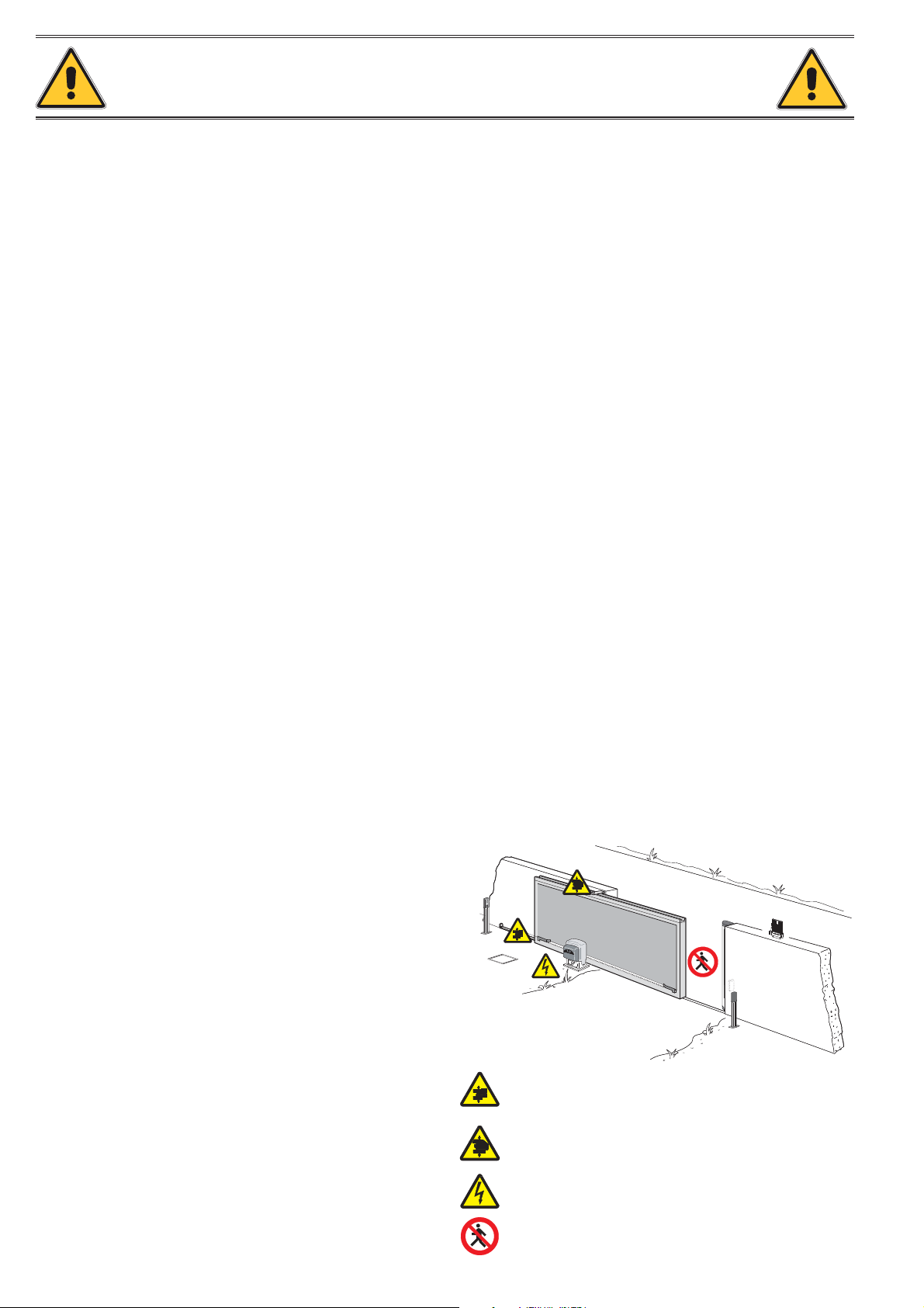
• Keep away from hinges and mechanical moving parts • Do not enter the
operator's area of operation when it is moving • Do not counter the operator's
movement as this could result in dangerous situations • Always pay special
attention to any dangerous points, which have to be labeled with specifi c
pictograms and/or black and yellow stripes • While using a selector switch or
a command in maintained actions, keep checking that there are no persons
within the operating range of any moving parts, until the command is released
• The gate may move at any time and without warning • Always cut o the
power supply before performing any maintenance or cleaning.
CA
M
E
Danger of foot crushing
Danger of hand crushing
Danger! High voltage.
No transiting while maneuvering
1 02/2015 © CAME Cancelli Automatici S.p.A . - The data and information in this manual may be changed at any time and without notice.
119 BJ0 4EN v.
2 - Manual code:
p.
Page 3
3
119 BJ 04 EN
1
LEGEND
This symbol shows which parts to read carefully.
This symbol shows which parts describe safety issues
⚠
This symbol shows which parts to tell users about.
☞
REFERENCE REGULATIONS
Came Cancelli Automatici S.p.A. is certified for the: ISO 9001 quality and ISO 14001 environmental management systems.
This product complies with the current regulations mentioned in the declaration of conformity.
DESCRIPTION
Operator complete with control board and mechanical end stops for sliding gates up to 2,200 kg in weight and 20 m in length.
Intended use
The operator is designed to power sliding gates used in apartment blocks and industrial plants.
Any installation and/or use other than that specified in this manual is forbidden.
Limits to use
Type BK-221E
Maximum door-leaf length (m) 20
Maximum door-leaf weight (kg) 2.200
Pinion module 4
Technical data
Type BK-221E
Protection rating (IP) 44
Power supply (V - 50/60 Hz) 230 AC
Power supply to motor (V - 50/60 Hz) 230 AC
Draw (A) 5.1
Standby consumption (W) 4.14
Green Power consumption (W) 0.58
Power rating (W) 580
Thrust (N) 1,5 00
Opening speed (m/min) 10.5
Duty cycle INTENSIVE USE
Operating temperature (°C) -20 ÷ +55
Condenser (μF) 22
Insulation class I
Motor's heat protection (°C) 150
Weight (kg) 21
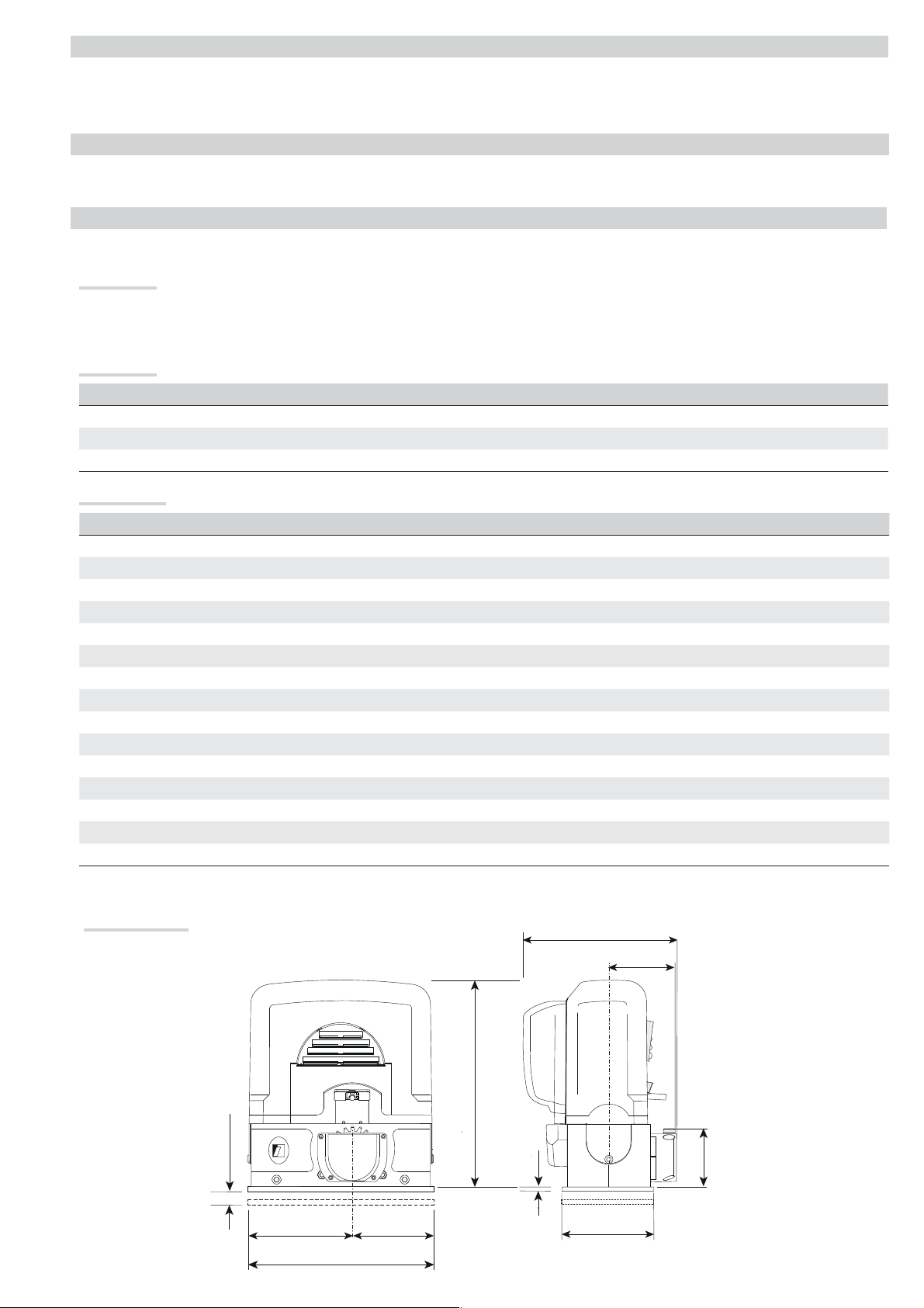
Dimensions (mm)
255
106
© CAME Cancelli Automatici S.p. A. - The data and information in this manual may be changed at any time and without notice..
360
1 02/2015
CAME
119 BJ0 4EN v.
3 - Manual code:
p.
22 max.
182.5
142.5
325
15
170
105
Page 4

4
119 BJ 04 EN
1
Description of parts
1. Cover
2. Gearmotor
3. Control board
4. Front cover
5. Anchoring plate
6. Nut plate
7. Nut
8. UNI5739 M12X70 screw
9. Control-board housing
10. Release key
11. Endstop fins
12. Mechanical endstop
13. UNI6954 3.9X13 screw
14. UNI6954 3.9X22 screw
15. Fan
16. Transformer
17. Encoder
18. Release hatch
1
1
4
17
13
2
16
7
12
6
11
8
15
7
6
10
5
18
9
3
4
8
14
Standard installation
1. Operator
10
66
11
8
7
2. Endstop fins
3. Rack
4. Key-switch selector
5. Flashing light
6. Photocells
7. Photocells post
8. Mechanical gate stop
9. Sensitive safety-edge
10. Junction pit
GENERAL INSTRUCTIONS FOR INSTALLING
Only skilled, qualified staff must install this product.
⚠
2
1
1
66
CAME
3
2
10 7
10 9
66
6
4
5
Preliminary checks
Before beginning the installation, do the following:
⚠
• check that the gate is stable and that the hinges are in good working order and lubricated;
• check that the ground guides are well fastened to the ground, completely on the surface and free of any irregularities that may obstruct the gate's
movement;
• check that the upper slide guides are free of any friction;
• make sure there are opening and closing mechanical gate stops;
• make sure that the point where the gearmotor is fastened is protected from any impacts and that the anchoring surface is solid enough.
• Make sure you have set up a suitable dual pole cut off device along the power supply that is compliant with the installation rules. It should completely
cut off the power supply according to category III surcharge conditions (that is, with minimum contact openings of 3 mm);;
• make sure that any connections inside the container (ones that ensure continuity to the protection circuit) are fitted with additional insulation with
respect to those of other electrical parts inside:
• set up suitable tubes and conduits for the electric cables to pass through, making sure they are protected from any mechanical damage.
1 02/2015 © CAME Cancelli Automatici S.p.A . - The data and information in this manual may be changed at any time and without notice.
119 BJ0 4EN v.
4 - Manual code:
p.
Page 5
5
119 BJ 04 EN
1
Tools and materials
Make sure you have all the tools and materials you will need for installing in total safety and in compliance with applicable regulations. The figure shows
some of the equipment installers will need.
Cable types and minimum thicknesses
Connection Cable type
Control panel power supply 230 V AC
230 V AC Flashing light 2 x 0.5 mm
Photocell transmitters 2 x 0.5 mm
Photocell receivers 4 x 0.5 mm
FROR CEI
20-22
CEI EN
50267-2-1
Cable length
1 < 10 m
3G x 1.5 mm
2
2
Command and safety device 2 x 0.5 mm
Cable length
10 < 20 m
3G x 2.5 mm
2
Cable length
20 < 30 m
3G x 4 mm
2
-2
2
2
Antenna RG58 max 10 m
Paired connection or CRP UTP CAT5 max 1000 m
If cable lengths differ from those specified in the table, establish the cable sections depending on the actual power draw of the connected devices
and according to the provisions of regulation CEI EN 60204-1.
For multiple, sequential loads along the same line, the dimensions on the table need to be recalculated according to the actual power draw and
distances. If connecting products that are not contemplated in this manual, see the literature accompanying said products
INSTALLATION
The following illustrations are mere examples in that the space for anchoring the operator and accessories varies depending on the installation
⚠
area. It is up to the installer to find the most suitable solution.
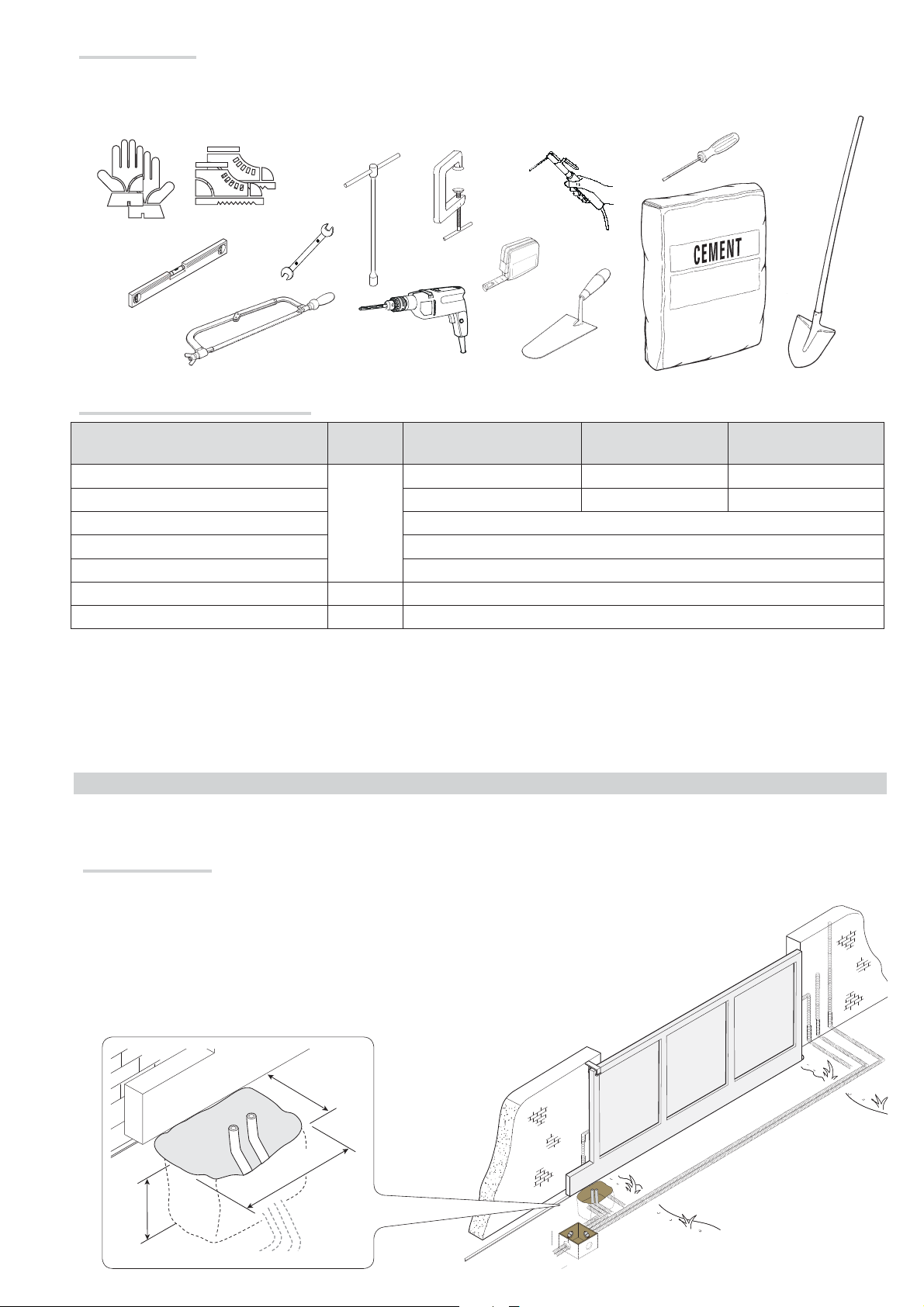
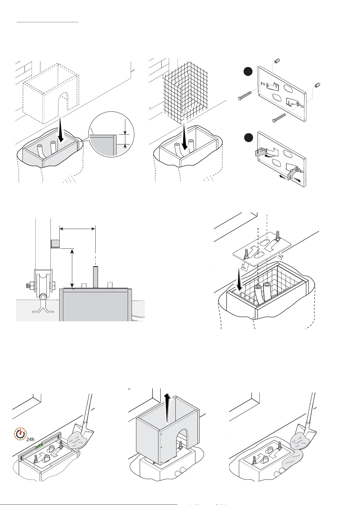
Corrugate tube laying
Dig a hole for the foundation frame.
Set up the corrugated tubes needed for making the connections coming out of the junction pit.
For connecting the gearmotor we suggest using a Ø 40 mm corrugated tube and Ø 25 mm tubes for the accessories.
The number of tubes depends on the type of system and the accessories you are going to fit.
© CAME Cancelli Automatici S.p. A. - The data and information in this manual may be changed at any time and without notice..
1 02/2015
119 BJ0 4EN v.
300
500
450
5 - Manual code:
p.
Page 6
50
6
119 BJ 04 EN
1
Laying the anchoring plate
Set up a foundation frame that is larger than the anchoring plate and sink it into the dug hole. The foundation frame must jut out by 50 mm above
ground level.
Fit an iron cage into the foundation frame to reinforce the concrete.
Fit the bolts into the fastening plate and lock using the nuts. Remove the pre-shaped anchors using a screwdriver or pliers.
1
2
If the rack is already there, place the anchoring plate, being careful to respect the measurements shown in the drawing.
Careful! The tubes must pass through their corresponding holes.
84
105
Fill the foundation frame with concrete. The plate must be perfectly level with the bolts which are entirely above surface.
Wait at least 24 hrs for the concrete to solidify.
Remove the foundation frame and fill the hole with earth around the concrete block.
1 02/2015 © CAME Cancelli Automatici S.p.A . - The data and information in this manual may be changed at any time and without notice.
119 BJ0 4EN v.
6 - Manual code:
p.
Page 7
7
119 BJ 04 EN
1
Remove the nut and washer from the bolts
Fit the electric cables into the tubes so that they come out about 600 mm.
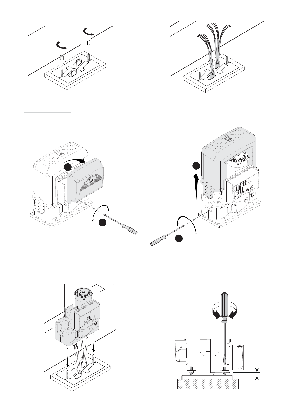
Setting up the gearmotor
Remove the front cover and gearmotor cover.
2
4
1
3
Place the gearmotor above the anchoring plate.
Careful! The electric cables must pass under the gearmotor box.
Lift the gearmotor by 5 to 10 mm from the plate by adjusting the threaded steel feet to allow any subsequent adjustments between pinion and rack.
© CAME Cancelli Automatici S.p. A. - The data and information in this manual may be changed at any time and without notice..
1 02/2015
5 ÷ 10
119 BJ0 4EN v.
7 - Manual code:
p.
Page 8
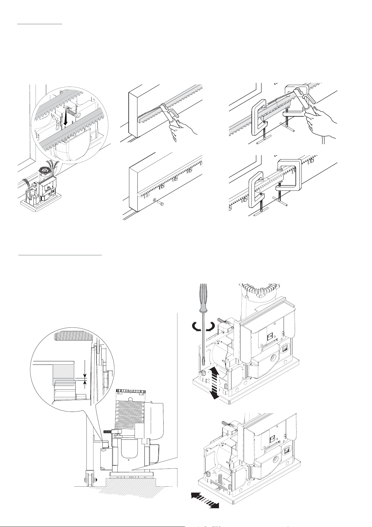
1 ÷ 2
8
119 BJ 04 EN
1
Fastening the rack
If a rack is already in place, move directly to adjusting the rack-pinion coupling distance, otherwise, follow the fastening instructions as explained
below:
- release the gearmotor (see gearmotor releasing paragraph);
- rest the rack (module 4) above the gearmotor pinion;
- weld or fasten the rack to the gate along its entire length.
To assemble the rack modules, use one its extra lengths, rest it under the joining point and lock it using two clamps.
Adjusting the pinion-rack coupling
Manually open and close the gate and adjust the pinion-rack coupling distance using the threaded feet (vertical adjustment) and the holes
(horizontal adjustment). This prevents the gate's weight to bear directly onto the operator.
1 02/2015 © CAME Cancelli Automatici S.p.A . - The data and information in this manual may be changed at any time and without notice.
119 BJ0 4EN v.
8 - Manual code:
p.
Page 9

9
119 BJ 04 EN
1
Fastening the gearmotor
Once adjusting is complete, fasten the gearmotor to the plate using the plates and nuts.
Establishing the endstop points
For opening:
- completely open the gate;
- fit the opening endstop fin onto the rack until the micro switch activates (spring);
- fasten it using the allen screws
Spring
For closing:
- completely close the gate;
- fit the closing endstop fin onto the rack until the micro-switch activates (spring);
- fasten it using the allen screws
Don't let the gate get to the mechanical stop, whether it is the opening or closing one.
⚠
2
1
22
© CAME Cancelli Automatici S.p. A. - The data and information in this manual may be changed at any time and without notice..
1 02/2015
119 BJ0 4EN v.
9 - Manual code:
p.
1
Page 10

10
119 BJ 04 EN
1
ELECTRICAL CONNECTIONS AND PROGRAMMING
Warning! Before working on the control panel, cut off the main current supply and, if present, remove any batteries.
⚠
Powering up the control board and command and control devices: 24 V AC/DC.
Functions on the input and output contacts, time adjustments and user-management settings are set and viewed on the programming board's display.
All connections are quick-fuse protected.
Fuses ZBKEP
- Line 6.3 A-T
- 1
- 1.6
A-F board
A-F accessories
Description of parts
1. Power supply terminals
2. Terminals for warning devices
3. Transformer terminals
4. Terminals for control and safety devices
5. Terminals for the GP1 module
6. Terminals for paired of CRP connection
7. Antenna terminal
8. RSE board connector
9. AF card connector
10. R700/R800 board connector
11. Memory roll board connector
1
L N
22
2
E1 EX W
6,3
21
20
3 4
24V 0
10 11 TS 1 2 3 3P 4 5 7 CX CY CZ
12. Terminals for transponder devices
13. Keypad selector terminal
14. Encoder terminals
15. Limit switch terminals
16. Programming buttons
17. Power supply on warning LED
18. Display
19. Gearmotor terminal
20. Control board fuse
21. Accessories fuse
22. Line fuse
5 6 7
+ STB -
A B GND
8
9
3
19
L1T L2T CT VS VF
U V W CAPACITOR
18
17
16
S1 GND
A B
+ E -
FC FA F
10
11
12
13
14
15
1 02/2015 © CAME Cancelli Automatici S.p.A . - The data and information in this manual may be changed at any time and without notice.
119 BJ0 4EN v.
10 - Manual code:
p.
Page 11

11
119 BJ 04 EN
1
Power supply
Red
Grey
Black
White
Brown
Terminals for powering 24 V AC - max
SP
4
3
24
2
17
1
0
FR
0
Blue
Orange
20 W accessories
Power supply 230 V AC
frequency 50/60 Hz
L N
L1T L2T CT VS VF
E1 EX W
24V 0
Factory wiring
The gearmotor is already connected.
To install on the right, Invert the gearmotor (U-V) and (FA-FC) endstop phases.
Encoder
COM
Orange
Limit switch
U V W CAPACITOR
Condenser
COM
Gearmotor 230 V AC
NC
NC
White
Motor torque limiter
To vary the motor torque, move the shown faston (the one with the black wire) to one of the 4 positions: 1 min – 4 max.
+
-
10 11 TS 1 2
Red
FC FA F
Brown
White
+ E -
Green
L1T L2T CT VS VF
Warning devices
© CAME Cancelli Automatici S.p. A. - The data and information in this manual may be changed at any time and without notice..
1 02/2015
Black
SP
4
3
2
1
FR
0
Cycle or courtesy light (contact rating: 230 V - 60 W max).
Auxiliary connection of an outdoor light which can be positioned where you like, to increase
lighting in the driveway/parking area.
Cycle: it stays lit from the moment that the gate leaf starts opening until it is completely
closed (including the automatic closing time).
Courtesy: it stays on for an adjustable time of between 60 to 180 seconds.
Movement flashing light (contact rating: 230 V - 25 W max). It flashes when the gate is
either opening or closing.
CAME
119 BJ0 4EN v.
11 - Manual code:
p.
E1 EX W
24V 0
10 11 TS 1 2 3 3P 4 5 7 CX CY CZ
Gate open warning light (Contact rating: 24 V - 3 W max).
Warns about the gate status, see function F 10.
+ STB -
A B GND
Page 12

12
119 BJ 04 EN
1
Command and control devices
Stop button (NC contact). For stopping the gate and excluding automatic closing.
For movement to resume, press the command button or other control device.
N.B.: if unused, select 0 (Deactivated) from function F 1.
ONLY OPEN function from control device (NO contact)
PARTIAL OPENING function from control device (NO contact)
ONLY CLOSE function from control device (NO contact)
OPEN-STOP-CLOSE-STOP sequential function / OPEN-CLOSE-INVERT stepstep from control device (NO contact). See function F 7.
10 11 TS 1 2 3 3P 4 5 7 CX CY CZ
Fit the R700 decoding card for the
⚠
TSP00 sensor or LT001 reader to be
R700
recognized.
+ STB -
A B GND
S1 GND
Red
Black
A B
Blue
White
Antenna with RG58 cable
AF
Keypad selector with R800 card
ACCESS CONTROL
CAME
AF card
Transponder or card reader with
R700 card
IFit the R800 decoding card for the the
⚠
S5000 keypad selector to be recognized.
R800
WARNING! For the system to work properly, before fitting any plug-in card, such as the AF or R800 one, YOU MUST CUT OFF THE
MAIN POWER SUPPLY and, if present, disconnect any batteries.
1 02/2015 © CAME Cancelli Automatici S.p.A . - The data and information in this manual may be changed at any time and without notice.
119 BJ0 4EN v.
12 - Manual code:
p.
Page 13

13
119 BJ 04 EN
1
Safety devices
Photocells
Configure contact CX, CY or CZ (NC), input for EN 12978
safety devices like photocells.
See CX input functions (Function F2), CY (Function F3) or CZ
(Function F4) in:
- C1 reopening during closing. When the gate is closing,
opening the contact triggers the inversion of movement until
the gate is fully open;
DIR
RX TX
photocells
DELTA-S
photocells
- C2 reclosing during opening. When the gate is opening,
opening the contact triggers the inversion of movement until
the gate is fully closed;
- C3 partial stop. Stopping of the gate, if it is moving, with
consequent automatic closing (if the automatic closing
function has be entered);
- C4 obstruction wait. Stopping of the gate, if it is moving,
which resumes movement once the obstruction is removed.
If unused, contacts CX, CY and CZ should be
deactivated during programming.
10 11 TS 1 2 3 3P 4 5 7 CX CY CZ
DELTA
RX TX
./ # .#
10 11 TS 1 2 3 3P 4 5 7 CX CY CZ
photocells
Sensitive Safety Edges
Configure contact CX, CY or CZ (NC), input for
EN 12978 safety devices such as sensitive
safety-edges. See input CX functions (Function
F2), CY (Function F3) or CZ (Function F4)
in:- C7 reopening during closing. When the
gate is closing, opening the contact triggers
the inversion of movement until the gate is
completely open;
- C8 reclosing during opening. When the
gate is opening, opening the contact triggers
the inversion of movement until the gate is
completely closed.
If unused, contacts CX, CY and CZ
© CAME Cancelli Automatici S.p. A. - The data and information in this manual may be changed at any time and without notice..
should be deactivated during programming.
1 02/2015
119 BJ0 4EN v.
DFW
DFW with control board for
DFI connections
10 11 TS 1 2 3 3P 4 5 7 CX CY CZ 2 3 3P 4 5 7 CX CY CZ
13 - Manual code:
p.
Page 14

+ STB -
24V 0
10 11 TS 1 2 3 3P 4 5 7 CX CY CZ
A B GND
A B GND
UTP CAT 5
1 2 3 4
1 2 3 4
14
119 BJ 04 EN
1
Photocell's safety connection
Upon each open or close command, the board verifies that the safety systems work. Any malfunction inhibits any command.
From function F 5 select onto which input to activate the connection.
DIR /
DELTA S
DELTA
+
C
10 2 T X
+
-
+
N.O.
C.
N.C.
-
+
NC
-
FUSIBILE 200m A
TX 2
TX
2
-
10 11 TS 1 2 3 3P 4 5 7 CX CY CZ
Functions managing devices
Connecting the RS485 serial with RSE board to the home automation
system via CRP (Came Remote Protocol) or for paired operation (see
chapter on PAIRED CONNECTION WITH A SINGLE CONTROL)
10 11 TS 1 2 3 3P 4 5 7 CX CY CZ
Fit the RSE card.
⚠
WARNING! YOU MUST CUT OFF THE
⚠
MAIN POWER SUPPLY and remove the
batteries - if present, before removing the
control board.
RSE
1 02/2015 © CAME Cancelli Automatici S.p.A . - The data and information in this manual may be changed at any time and without notice.
119 BJ0 4EN v.
14 - Manual code:
p.
Page 15

15
119 BJ 04 EN
1
Description of programming commands
Display
Browsing the menu
To enter the menu, keep the ENTER
button pressed for at least one
second.
F
{
{
{
The ESC button is for:
- exiting menus;
- cancelling changes.
The < > keys are for:
- moving from one item to another;
- increasing or decreasing values.
The ENTER key is for:
- entering menus;
- confirming or memorizing set values.
i
To select menu items,
use the arrow keys ...
also for the submenus,
use the arrow keys to
select ...
To increase or decrease
a value, use the arrow
keys ...
F
i
F
2
3
... then press ENTER
F
0
i
... then press ENTER
03
i3
... the press ENTER to
confirm ...
© CAME Cancelli Automatici S.p. A. - The data and information in this manual may be changed at any time and without notice..
1 02/2015
When the menu is active the system cannot be viewed.
119 BJ0 4EN v.
15 - Manual code:
p.
... to exit the menu, wait 10 seconds or
press ESC.
Page 16

16
119 BJ 04 EN
1
Functions map
F 1 Total stop function (1-2)
F 2 Function associated to input 2-CX
F 3 Function associated to input 2-CY
F 4 Function associated to input 2-CZF 5 Safety test function
F 6 Maintained action function
F 7 Control mode on 2-7
F 9 Obstruction detection with motor idle function
F 10 Warning light function
F 11 Encoder exclusion
F 14 Sensor type selection function
F 18 Additional light function
F 19 Automatic closing time
F 20 Automatic closing time after partial opening
F 21 Preflashing time
F 22 Working time
F 25 Courtesy light time
F 30 Adjusting gearmotor slow-down speed
F 34 Sensitivity during movement
F 35 Sensitivity during slow-down
F 36 Adjusting partial opening
F 37 Adjusting the gearmotor's opening slow-down starting point
F 38 Adjusting the gearmotor's closing slow-down starting point
F 49 Managing functions
F 50 Saving data in the memory roll
F 51 Reading memory roll data
F 52 Passing settings in paired/alternating mode
F 54 Opening direction
F 56 Peripheral number
F 63 Changing COM speed
F 71 Partial opening time
U 1 Entering new user with an associated command
U 2 Deleting single users
U 3 Deleting all users
A 3 Calibrate gate run
A 4 Reset settings
A 5 Counting the number of maneuvers
H 1 Software version
Functions menu
IMPORTANT! Begin programming by first performing the following functions: OPENING DIRECTION (F54), TOTAL STOP (F1) and
TRAVEL CALIBRATION (A3).
Programming the features is to be done when the operator is stopped.
⚠
You can memorize up to 25 users.
F1 Total stop [1-2] 0 = Deactivated (default) / 1 = Activated
NC input – Gate stop that excludes any automatic closing; to resume movement, use the control device. Fit the safety device onto [1-2].
F2 Input [2-CX] 0 = Deactivated (default) / 1 = C1 / 2 = C2 / 3 = C3 / 4 = C4 / 7 = C7 / 8 = C8
NC input – Can associate: C1 = reopening during closing by photocells, C2 = reclosing during opening by photocells, C3 = partial stop, C4 =
obstruction wait, C7 = reopening during closing by sensitive safety-edges, C8 = reclosing during opening by sensitive safety-edges.
1 02/2015 © CAME Cancelli Automatici S.p.A . - The data and information in this manual may be changed at any time and without notice.
F3 Input [2-CY] 0 = Deactivated (default) / 1 = C1 / 2 = C2 / 3 = C3 / 4 = C4 / 7 = C7 / 8 = C8
NC input – Can associate: C1 = reopening during closing by photocells, C2 = reclosing during opening by photocells, C3 = partial stop, C4 =
obstruction wait, C7 = reopening during closing by sensitive safety-edges, C8 = reclosing during opening by sensitive safety-edges.
119 BJ0 4EN v.
16 - Manual code:
p.
Page 17

17
119 BJ 04 EN
1
F4 Input [2-CZ] 0 = Deactivated (default) / 1 = C1 / 2 = C2 / 3 = C3 / 4 = C4 / 7 = C7 / 8 = C8
NC input – Can associate: C1 = reopening during closing by photocells, C2 = reclosing during opening by photocells, C3 = partial stop, C4 =
obstruction wait, C7 = reopening during closing by sensitive safety-edges, C8 = reclosing during opening by sensitive safety-edges.
F5 Safety test
0 = Deactivated (default) / 1 = CX / 2 = CY / 3 = CZ / 4 = CX+CY / 5 = CX+CZ / 6 = CY+CZ / 7 = CX+CY+CZ
After every opening or closing command, the board will check whether the photocells are working properly.
F6 Maintained action 0 = Deactivated (default) / 1 = Activated
The gate opens and closes by keeping the button pressed. Opening button on contact [2-3] and closing button on contact [2-4]. All other
control devices, even radio ones, are excluded.
F7 Command [2-7] 0 = step-step (default) / 1 = sequential
Step-step = open-close, sequential = open-stop-close-stop.
F9 Obstruction detection with motor idle 0 = Deactivated (default) / 1 = Activated
With the gate closed, opened or totally stopped, the gearmotor stays idle if the safety devices, that is, photocells or sensitive safety-edges
detect an obstruction.
F10 Warning light 0 = lit when gate is open or moving (default) /
1 = when opening it fl ashes intermittently every half-second
when closing it fl ashes intermittently every second
stays lit when gate is open
is o when gate is closed
It warns of the gate status. The bulb is connected to contact 10-5.
F11 Encoder 0 = Active (default) / 1 = Deactivated
Managing slow-downs, obstruction detections and sensitivity.
F14 Sensor type selection 0 = transponder sensor or magnetic card reader command
1 = keypad selector command ( default)
Setting the type of sensor for controlling the operator.
F18 Additional light 0 = Deactivated (default) / 1 = Cycle / 2 = Courtesy
Output on contact [E1-EX].
The cycle lamp stays lit from the beginning of the opening until complete closing, including the waiting time before the automatic closing.
The courtesy light stays lit for an adjustable time - see function F 25.
F19 Automatic closing time 0 = Deactivated (default) / 1 = 1 s / 2 = 2 s / … / 180 = 180 s
The wait before the automatic closing starts when the opening end point is reached, and can be adjusted to between 1 s and 180 s. The
automatic closing does not activate is any of the safety devices trigger when an obstruction is detected, after a total stop or during a power
outage.
F20 Automatic closing time after a partial opening 0 = Deactivated (default) / 1 = 1 s / 2 = 2 s / … / 180 = 180 s
The wait before the automatic closing starts after a partial opening command for an adjustable time of between 1 s and 180 s.
The automatic closing does not activate is any of the safety devices trigger when an obstruction is detected, after a total stop or during a
power outage.
F19 must not be deactivated.
F21 Prefl ashing time 0 = Deactivated (default) / 1 = 1 s / 2 = 2 s / … / 10 = 10 s
When an opening or closing command is sent, the fl ashing light on [W-E1] fl ashes before starting the maneuver. The fl ashing time is
adjustable to between 1 s and 10 s.
F22 Working time 30 = 30 s / ...../ 90 = 90 s (default) /...../ 120 = 120 s
Gearmotor working time during opening and closing.
© CAME Cancelli Automatici S.p. A. - The data and information in this manual may be changed at any time and without notice..
The working time can be adjusted to between 30 s and 120 s
F25 Courtesy light time 60 = 60 s /....... / 180 = 180 s.
1 02/2015
Additional light connected to E1-EX, stays lit for the necessary time while the gate is opening and closing.
the time can be set to between 60 s. and 180 s.
119 BJ0 4EN v.
F30 Slow-down speed 0 = Deactivated / 1 = Maximum speed / 2 = Intermediate speed (default) / 3 = Minimum speed.
Setting the gearmotor speed during the slow-down stages.
F34 Gate travel sensitivity 10 = maximum sensitivity / … / 100 = minimum sensitivity (default)
17 - Manual code:
Adjusting obstruction detection sensitivity during gate travel.
p.
Page 18

18
119 BJ 04 EN
1
F35 Slow-down sensitivity 10 = maximum sensitivity / … / 100 = minimum sensitivity (default)
Adjusting obstruction detection sensitivity during slow-down.
F36 Adjusting partial opening 10 = 10% of the gatetravel ( default ) / … / 80 = 80% of the gate travel
Adjustment as a percentage of total travel, during gate opening.
F37 Opening slow-down point 10 = 10% of the travel / … / 25 = 25% of thetravel ( default ) / … / 60 = 60% of the travel
Percentage adjustment of the total gate travel, of the opening slow-down starting point.
F38 Closing slow-down point 10 = 10% of the travel / … / 25 = 25% of thetravel ( default ) / … / 60 = 60% of the travel
Percentage adjustment of the total gate travel, from the closing slow-down starting point.
F49 Managing functions
0 = Deactivated (default) / 1 = Paired / 3
= CRP
To enable paired operation or the Came Remote Protocol.
F50 Save data 0 = Deactivated (default) / 1 = Activated
Saving users and saved settings in memory roll.
This feature only appears if a memory roll has been fi tted into the control board.
F51 Read data 0 = Deactivated (default) / 1 = Activated
Uploading data saved in memory roll.
This feature only appears if a memory roll has been fi tted into the control board.
F52 Passing settings in paired/alternating mode 0 = Deactivated (( default) / 1 = Activated
Uploading settings from Master to Slave.
This appears only if function F49 is set to Paired.
F54 Opening direction 0 = Opening left (default) / 1 = Opening right
For setting the gate opening direction.
F56 Peripheral number 1 ----> 225
To set the peripheral's number from 1 to 255 for each control board when you have a system with several operators.
F63 Change COM speed
0=1200 Baud / 1=2400 / 2=4800 / 3=9600 / 4=14400 / 5=19200 / 6=38400 / 7=57600 / 8=115200 Baud
For setting the communication speed used in the CRP (Came Remote Protocol) connection system.
F71 Partial opening time 5 = 5 seconds /....... / 40 = 40 seconds.
After an opening command from the button connected to 2-3P, the gate opens for an adjustable time of between 5 s. and 40 s.
The function appears only if the «Encoder» feature is deactivated (see function F11)
U 1 Entering a user 1 = Step-step command (open-close) / 2 = Sequential command (open-stop-close-stop) / 3 = Open
only command / 4 = Partial command / 5 = contact B1-B2 output
Entering up to a 25 users maximum and associating to each one a function chosen among the existing ones. This must be done via
transmitter or other control device (see " entering use with associated command" paragraph).
U 2 Deleting a user
Deleting single users.
U 3 Deleting users 0 = Deactivated / 1 = Deleting all users
Deleting all users.
A 3 Calibrate gate run 0 = Disable / 1 = Activate
Automatic calibration of the gate travel (see calibrating gate travel paragraph)
A 4 Reset parameters 0 = Disable / 1 = Activate
Careful! If necessary you can restore the default settings using the following function:
Restoring default settings and cancelling gate travel calibration operation.
A 5 Manoeuvre counter 0 = Number of manoeuvres made / 1 = Deleting all manoeuvres
For either viewing the number of manoeuvres made or deleting them ( 001 = 100 manoeuvres; 010 = 1000 manoeuvres;
100 = 10000 manoeuvres; 999 = 99900 manoeuvres; CSI = maintenance job)
H 1 Version
View the software version.
1 02/2015 © CAME Cancelli Automatici S.p.A . - The data and information in this manual may be changed at any time and without notice.
119 BJ0 4EN v.
18 - Manual code:
p.
Page 19

19
119 BJ 04 EN
1
Entering a user with an associated command
When entering / deleting users, the fl ashing numbers you see, are available numbers which are usable for entering subsequent
users (max. 25 users).
Select U 1
Press ENTER to confirm.
Select a command to associate to the user.
The commands are:
- step-step (open-close) = 1;
- sequential (open-stop-close-stop) = 2;
- open = 3;
- partial opening/pedestrian = 4.
Press ENTER to confirm...
... a number from 1 to 25 will flash for a few
seconds
Send the code from the transmitter or other
control device, such as, a keypad selector or a
transponder.
Associate the number to the entered user.
2
iU
2
5
User Associated command
1 2 3 4 5 6 7 8 9 10 11 12 13 14 15 16 17 18 19 20 21 22 23 24 25 -
Deleting a single user
Select U 2.
Press ENTER to confirm.
© CAME Cancelli Automatici S.p. A. - The data and information in this manual may be changed at any time and without notice..
Use the arrow keys select the number of the
user you wish to delete.
1 02/2015
Press ENTER to confirm...
119 BJ0 4EN v.
... Clr will appear on the screen to confirm
deletion.
19 - Manual code:
p.
U
2
C l
2
2
Page 20

L
20
119 BJ 04 EN
1
Travel calibration
Before calibrating the gate travel, position the gate half-way, check that the maneuvering area is clear of any obstruction and check
⚠
that there are mechanical opening and closing stops.
The mechanical end-stops are obligatory.
⚠
Important! While calibrating, all of the safety devices will be disabled excluding the TOTAL STOP one.
Select A 3.
Press ENTER to confirm.
A 3
Select 1 and press ENTER to
confirm the travel calibration
operation.
i
The gate will perform a closing
maneuver until it reaches a final
stop...
iCL
...then the gate will perform
an opening maneuver until it
reaches a final stop.
Memory Roll Card
To memorize user data and configure the system, to then reuse them with another control board even on another system.
After memorizing the data, it is best to remove the memory roll.
L N
O
E1 EX W
P
i
10 11 TS 1 2 3 3P 4 5 7 CX CY CZ
24V 0
+ STB -
A B GND
L1T
1 02/2015 © CAME Cancelli Automatici S.p.A . - The data and information in this manual may be changed at any time and without notice.
Memory roll
119 BJ0 4EN v.
20 - Manual code:
p.
Page 21

A B GND
A B GND
21
119 BJ 04 EN
1
PAIRED CONNECTION WITH A SINGLE CONTROL
Connections
Only perform on the MASTER board terminals Ⓐ any connections of the control,
warning and safety devices.
Connect the two boards using a UTP CAT
5 cable on terminals A-B-GND and fit the
RSE board into both boards.
1 2 3 4
UTP CAT 5
1 2 3 4
A
Programming
Set the functions on the MASTER board
as follows:
- from function F49, select 1=Paired and
press ENTER to confirm.
- from function F52, select 1 and press
ENTER to activate the data passage from
the MASTER board Ⓐto the SLAVE board
Ⓑ.
FINAL OPERATIONS
Once you have finished making all the electrical connections and powered up the operator, fit the cover while making sure not to damage any cables.
Fasten using screws.
1
9 F 4
2 F 5
3
B
I
I
4
2
RELEASING THE GEARMOTOR
This procedure must be done with the main power cut o .
⚠
Manually releasing the operator may result in uncontrolled movement of the gate, if this has any mechanical problems or is unbalanced.
⚠
© CAME Cancelli Automatici S.p. A. - The data and information in this manual may be changed at any time and without notice..
1 02/2015
2
119 BJ0 4EN v.
1
21 - Manual code:
p.
1
4
3
5
Page 22

22
119 BJ 04 EN
1
ERROR MESSAGES
Error messages appear on the display.
E 1 The gate travel calibration was interrupted by the activation of the STOP button.
E 2 Gate travel calibration incomplete.
E 3 Encoder is broken.
E 4 Services test error
E 7 Insufficient working time
E 8 Release hatch open
E 9 Closing obstruction.
E 10 Opening obstruction.
E 11 Maximum number of obstructions detected.
E 13 The NC contacts are open (e.g. limit switches).
E 14 Serial communication error.
TROUBLESHOOTING
PROBLEM POSSIBLE CAUSES FIXES
It neither opens nor
closes
• Power supply missing
• The gearmotor is stuck
• The transmitter's battery is run down
• The transmitter is broken
• The Stopbutton is either stuck or broken
• The opening/closing button or the key-switch selector
• Check whether the power is on
• Lock the gearmotor
• Replace the batteries
• Call for assistance
• Call for assistance
• Call for assistance
is stuck
The gate opens but
does not close
• The photocells are dirty
• Automatic closing is disabled
• Clean and check proper functioning of the photocells
• Check whether function F 19 is activated
MAINTENANCE LOG
Periodic maintenance
☞ Before doing any maintenance, cut off the power supply, to prevent any hazardous situations caused by accidentally activating the operator.
Periodic maintenance log kept by users (every six months)
Date Notes Signature
1 02/2015 © CAME Cancelli Automatici S.p.A . - The data and information in this manual may be changed at any time and without notice.
119 BJ0 4EN v.
22 - Manual code:
p.
Page 23

23
119 BJ 04 EN
1
Extraordinary maintenance
The following table is for logging any extraordinary maintenance jobs, repairs and improvements performed by specialized contractors.
⚠
N.B.: extra-ordinary maintenance jobs must be performed by skilled technicians.
Extraordinary maintenance log
Fitter's stamp Name of operator
Job performed on (date)
Technician's signature
Requester's signature
Job performed ___________________________________________________________________________________________
______________________________________________________________________________________________
DISMANTLING AND DISPOSAL
CAME CANCELLI AUTOMATICI S.p.A. employs a certified Environmental Management System at its premises, compliant with the UNI EN ISO
☞
14001 standard to ensure the environment is safeguarded.
Please continue safeguarding the environment. At CAME we consider it one of the fundamentals of our operating and market strategies. Simply
follow these brief disposal guidelines:
DISPOSING OF THE PACKAGING
The packaging materials (cardboard, plastic, and so on) should be disposed of as solid urban waste, and simply separated from other waste for
recycling.
Always make sure you comply with local laws before dismantling and disposing of the product.
DO NOT DISPOSE OF IN NATURE!
DISMANTLING AND DISPOSAL
Our products are made with different materials. Most of these (aluminum, plastic, iron, electrical cables) is classified as solid urban waste. They can
be recycled by separating them before dumping at authorized city dumps.
Whereas other components (control boards, batteries, transmitters, and so on) may contain hazardous pollutants.
These must therefore be disposed of by authorized, certified professional services.
Before disposing, it is always advisable to check with the specific laws that apply in your area.
© CAME Cancelli Automatici S.p. A. - The data and information in this manual may be changed at any time and without notice..
DO NOT DISPOSE OF IN NATURE!
1 02/2015
DECLARATION OF CONFORMITY
Declaration - Came Cancelli Automatici S.p.A. declares that this device conforms to the essential, pertinent requirements provided by directives
2006/42/CE and 2004/108/CE.
119 BJ0 4EN v.
An original copy of the declaration of conformity is available on request.
23 - Manual code:
p.
Page 24

IT • Per ogni ulteriore informazione su azienda, prodotti e assistenza nella vostra lingua:
CAME S.p. A.
Dos son Di Casier
Assi stenza Tec nic a/Numero Verde 80 0 2 95830
www. came.com
En g l i s h
119 BJ 04 EN
1
EN • For any further information on company, products and assistance in your language:
FR • Pour toute autre information sur la société, les produits et l’assistance dans votre langue :
DE • Weitere Infos über Unternehmen, Produkte und Kundendienst in Ihrer Sprache bei:
ES • Para cualquier información sobre la empresa, los productos y asistencia en su idioma:
NL • Voor meer informatie over het bedrijf, de producten en hulp in uw eigen taal:
PT • Para toda e qualquer informação acerca da empresa, de produtos e assistência técnica, em sua língua:
PL •
Wszystkie inne informacje dotyczące fi rmy, produktów oraz usług i pomocy technicznej w Waszym języku znajdują się na stronie:
RU •
Для получения дополнительной информации о компании, продукции и сервисной поддержке на вашем языке:
HU • A vállalatra, termékeire és a műszaki szervizre vonatkozó minden további információért az Ön nyelvén:
HR • Za sve dodatne informacije o poduzeću, proizvodima i tehničkoj podršci:
UK • Для отримання будь-якої іншої інформації про компанію, продукцію та технічну підтримку:
www. came.com
1 02/2015 © CAME Cancelli Automatici S.p.A .
119 BJ0 4EN v.
En g l i s h - Manual code:
The data and information in this manual may be changed at any time and without notice from CAME Cancelli Automatici S.p.A.
CAME S.p.A.
Via Martiri Della Libertà, 15
31030
Dosson Di Casier (Tv)
(+39) 0422 4940
(+39) 0422 4941
Assistenza Tecnica/Numero Verde 800 295830
 Loading...