

Page 1
CANCELLI AUTOMATICI
SERIE BK |
BK SERIES |
SÉRIE BK|
BAUREIHE BK|
SERIE BK
BK 2200T
Automazioni per cancelli scorrevoli
Automation systems for sliding gates
Automatisme pour pourtails coulissants
Antriebe für den Schiebetore
Documentazione
Tecnica
S54
rev. 1.2
12/2002
©
CAME
CANCELLI
AUTOMATICI
119BS54
10
10
11
11
2 x 1 - TX
Automatización para puertas correderas
4
1
1
9
9
5
5
4
4
10
10
9
9
6
6
7
2 x 1
7 x 2,5
4 x 1 - RX
4 x 1 - RX
3 x 1
4 x 1 - RX
4 x 1 - RX
2 x 1 - TX
2 x 1 - TX
2 x 1.5
2 x 1.5
RG58
8
8
2
323
12
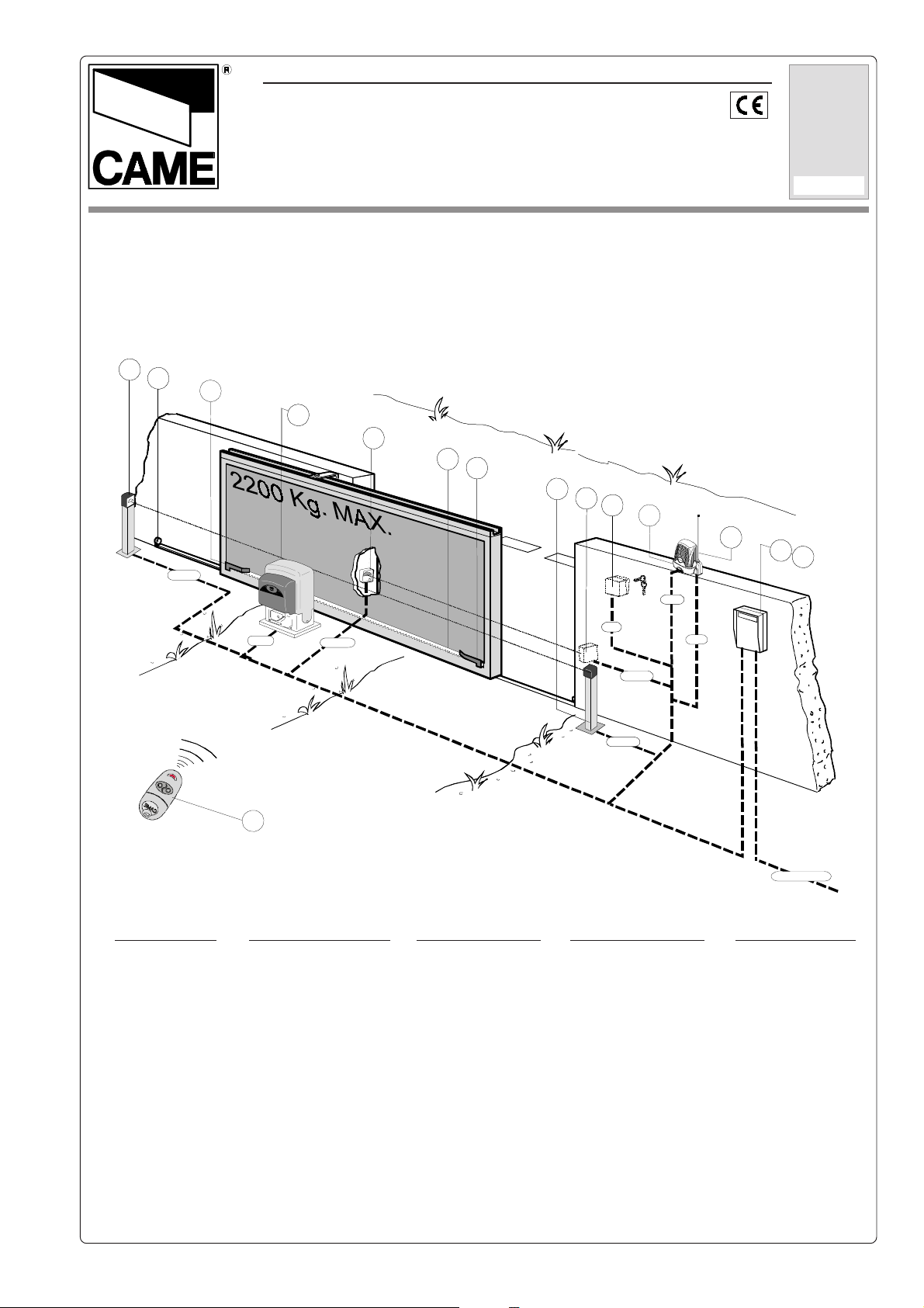
Impianto tipo Installation type
1 - Gruppo BK
2 - Quadro comando
ZT4
3 - Ricevitore radio
4 - Alette finecorsa
5 - Cremagliera
6 - Selettore a chiave
7 - Lampeggiatore di
movimento
8 - Antenna di ricezione
9 - Fotocellule di
sicurezza
10 - Colonnina per
fotocellula
11 - Fermo anta
12 - Trasmettitore
Standard installation
1 - BK unit
2 - ZT4 control panel
3 - Radio receiver
4 - Limit-switch tabs
5 - Rack
6 - Key-operated selector
switch
7 - Flashing light indica-
ting door movement
8 - Antenna
9 - Safety photocells
10 - Photocell column
11 - Closure stop
12 - Transmitter
1 - Groupe BK
2 - Armoire de comman-
de ZT4
3 - Récepteur radio
4 - Buttées fin de
course
5 - Crémaillère
6 - Sélecteur a clé
7 - Clignotant de
mouvement
8 - Antenne de réception
9 - Photocellules de
sécurité
10 - Colonne pour
photocellule
11 - Butée d'arrêt
12 - Emmetteur
Standard montage
1 - BK Antriebsmotor
2 - Schalttafel ZT4
3 - Funkempfänger
4 - Endschalterwinkel
5 - Zahnstange
6 - Schlüsselschalter
7 - Blinkleuchte “Tor in
Bewegung”
8 - Außenantenne
9 - R Lichtschranke
10 - Lichtschrankeensäule
11 - Toranschlag
12 - Funksender
4 x 2.5 / 230/400V
Instalación tipo
1 - Conjunto BK
2 - Cuadro de mando
ZT4
3 - Radiorreceptor
4 - Aletas de tope
5 - Cremallera
6 - Selector mediante
llave
7 - Lámpara intermiten-
te de movimiento
8 - Antena receptora
9 - Fotocélulas de
seguridad
10 - Columna para
fotocélula
11 - Tope puerta
12 - Transmisor
Page 2
CARATTERISTICHE GENERALI -
GENERAL SPECIFICATIONS
CARACTERÍSTICAS GENERALES
- CARACTÉRISTIQUES GÉNÉRALES -
ALLGEMEINES
DESCRIZIONE
Progettato e costruito
interamente dalla
CAME, BK risponde
alle vigenti norme di
sicurezza, con grado di
protezione IP54.
Garantito 24 mesi salvo manomissioni.
MODELLO
BK 2200 T
Modulo pignone m6
portata max 2200 Kg
ACCESSORI
Quadro elettrico ZT4.
CARATTERISTICHE TECNICHE -
DESCRIPTION
Designed and constructed entirely by
CAME;conforms
to,safety standards with
IP 54 protection rating.
24 mounth guarantee;
guarantee void if unit is
tampered with.
VERSION
BK 2200 T
Pinion module m6
max capacity 2200 Kg
ACCESSORIES
ZT4 control panel.
TECHNICAL CHARACTERISTICS -
TECNISCHE DATEN -
DESCRIPTION
Il a été entièrement
conçu et realisé par les
Ets CAME, conformément aux normes de
sécurité en vigueur
avec degré de protection IP54.
Il est garanti 24 mois
sauf en cas d'endommagement.
VERSION
BK 2200T
Module pignon m6
portée max 2200 Kg
ACCESSOIRES
Armoire de commande
ZT4.
CARACTERISTICAS TECNICAS
BASCHREIBUNG
Vollständig von der
CAME geplant und
hergestellt, entsprechend den geltenden
Sicherheits-bedigungen
mit Schutzgrad IP54.24
Monate Garantie,
Bedienungs - und
DESCRIPCIÓN
Diseñado y construido
totalmente por CAME,
con arreglo a las
vigentes normas de
seguridad con grado
de protección IP54.
Garantia de 24 meses
salvo manipulaciones.
Montage-fehler
ausgeschlossen.
AUSFÜHRUNGEN
BK 2200T
Ritzeleinheit m6
Max Tragfähigkeit 2200 kg
ZÜBEHOR
Schalttafel ZT4.
MODELO
BK 2200T
Módulo piñón m6
capacidad máx 2200 Kg
ACCESORIOS
Cuadro de mando ZT4.
CARACTERISTIQUES TECHNIQUES
EROTTUDIROTOM OSEP ENOIZATNEMILA OTNEMIBROSSA AZNETOP
ROTOMRAEG THGIEW YLPPUSREWOP TNERRUC REWOP ELCICYTUD EUQROTXAM
RUETCUDÉROTOM SDIOP NOITATNEMILA NOITPROSBA ECNASSIUP
ROTOMEBEIRTEG THCIWEG
ROTCUDERROTOM OSEP NOICATNEMILA AICNEBROSBA AICNETOP
T0022KB gK12 .c.aV004-V032 A5,1 W006 %05 mN06* 13/1 N0561 nim/m5,01
* Ottenuta mediante quadro comando CAME /
* Regulierbarer schub erreicht mit Hilfe der CAME Motorsteuerrung /
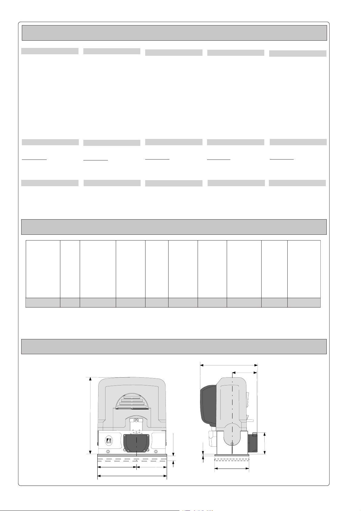
MISURE D'INGOMBRO -
_MORTS
GNUGROSREV
OVERALL DIMENSIONS
360
_FUAMORTS
EMHAN
* Obtained with CAME control panel /
GNUTSIEL
* Empuje regulable obtenido mediante tablero de control CAME
- MESURES D'ENCOMBREMENT -
AZNETTIMRETNI
OROVAL
ECNETTIMRETNI
LIAVARTED
_TLAHCSNIE
REUAD
AICNETIMRETNI
OJABART
AIPPOC
ELPUOC
TNEMOMHERD
AJERAP
)ROTOM(
* Obtenue avec une armoire de commande CAME
255
IDOTROPPAR
ENOIZUDIR
NOITCUDER
OITAR
EDTROPPAR
NOITCUDER
_SGNUZTESRETNU
SINTLÄHREV
EDNOICALER
NOICCUDER
ABMESSUNGEN
106
ATNIPS .XAM'ATICOLEV
HSUP DEEPS.XAM
EÉSSUOP .XAMESSETIV
RERABLEGER
EJUPME .XAMDADICOLEV
- MEDIDAS
.XAM
SGNUGARTREBÜ
325
22 max
142,5182,5
- 2 -
15
170
105
(mm)
Page 3
PRIMA DI INSTALLARE ... -
VOR DEN INSTALLATION ÜBERPRÜFEN
BEFORE INSTALLING ...
- AVANT D'INSTALLER L'AUTOMATISME ...
... - ANTES DE INSTALAR EL AUTOMATISMO ...
- Controllare che l'anta sia
rigida e che le ruote di
scorrimento siano in
buono stato e adeguatamente ingrassate.
- La guida a terra dovrà
essere ben fissata al suolo, completamente in superficie in tutta la sua lunghezza e priva di irregolarità che possano ostacolare il movimento del
cancello.
- I pattini-guida superiori
non devono creare attriti.
- Prevedere una battuta
d'arresto in apertura e
una in chiusura.
- Preparare il percorso dei
cavi elettrici come da impianto tipo.
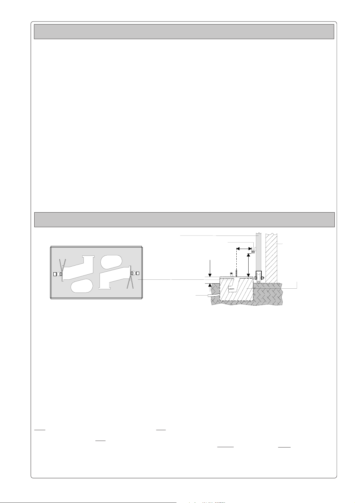
FISSAGGIO BASE MOTORE -
Inserire le viti nella piastra
di ancoraggio bloccandole con un dado, ed estrarre le zanche preformate
verso il basso.
Predisporre, dimensionandola in base alle misure del motoriduttore, una
piazzola in cemento (si
consiglia di farla sporgere
dal terreno di circa 50 mm.)
con annegata la piastra di
ancoraggio e relative
zanche sulla quale sara'
fissato il gruppo.
La base di fissaggio dovra'
risultare perfettamente in
bolla, pulita in tutte le sue
estremita', con il filetto
delle viti completamente
in superfice.
N.B.: Dalla stessa dovranno emergere i tubi flessibili per il passaggio dei
cavi di collegamento elettrico.
- The gate must be sufficiently rigid and solid; the
wheels on which the gate
slide must be in perfect
condition and adequately
lubricated.
- The wheel guide must be
firmly attached to the
ground, completely exposed, and without any irregular sections which
might hinder the movement
of the gate.
- The upper guide must allow for the correct amount
of play in order to guarantee smooth and silent
movement of the gate.
- Aperture and closure stops
must be installed.
- The wiring must be routed
as specified by the control
and safety requirements.
- Le panneau mobile du
portail devra être suffisamment rigide et solide;
les roues de coulissement devront être en très
bon état. En outre, elles
devront être convenablement graissées.
- Le rail de guidage devra
être bien fixée au sol. De
plus, il devra se présenter entièrement en surface sans irrégularités
(qui pourraient empêcher
le mouvement du portail).
- Le guide supérieur devra
avoir un jeu convenable
avec le portail (pour permettre un mouvement
régulier et silencieux).
- Prévoir une butée d’arrêt
à l’ouverture et à la fermeture.
- Prévoir le passage des
câbles électriques selon
les dispositions de commande et de sécurité.
MOTOR TO BASE ANCHORAGE
BEFESTIGUNGS DER MOTORBASIS
Anta cancello
Gate wing
Panneau mobile du portail
Gleitachse
Puerta
Piastra di ancoraggio / Zanche
Fixing plat e / Anchor stays
Plaque de fixation / Agrafes
Gleitachse / Verankerung
Placa de fijación / Barras de fijción
Install the screws in the
anchor plate and fasten them
with a nut, then bend the
pre-formed clamps
downwards. Construct a
cement foundation that is
large enough to accomodate the gear motor (it is a
good idea to protrude 50 mm.
from the ground). When
pouring the foundation,
embed the gear motor
anchor plate and the relative
clamps in the cement. The
anchor bolts should be
embedded in the concrete in
the positions indicated; the
drive unit is then attached to
this bots. The anchor plate
must be perfectly level and
absolutly clean; the bolts
threads must be completly
exposed.
N.B.: The flexible tubes for
the electrical wiring must be
embedded in the base and
protude in the correct
position.
Introduire les vis dans la
plaque d'ancrage en les
bloquant avec un écrou, et
replier les agrafes préformées ver le bas. Préparer
une base en ciment d'une
dimension adéquate aux
mesures du
motoréducteur (il est conseillé de la faire dépasser
du terrain d'environ 50
mm.), et noyer dedans la
plaque d'ancrage et les
agrafes correspondantes
afin de permettre le fixage
du groupe. La base de fixation devrà être parfaitement de niveau et propre
sur toute sa surface et le
filet des vis devra être complètement en surface.
N.B. Les câbles pour le
branchement électrique
devront sortir de cette
base.
- Die Leistungfähigkeit der
feststehenden und beweglichen Teile des Tores
überprüfen; das Tor sollte
ausreichend stabil sein.
Die Gleitrollen sollten in
guten Zustand und angemessen geschmiert sein.
- Die Gleitführung auf dem
Boden sollte sich in optimaler Position befinden:
gut auf dem Boden befestigt, in seiner Gesamtlänge
vollständig über dem Boden, ohne Vertiefungen
und/oder Unebenheiten,
die die Torbewegung behindern können.
- Die oberen Führungsschienen sollten das richtige Spiel zum Tor haben,
um ein präzises und regelmäßiges Gleiten zu garantieren.
- Einen Anschlag für Tor Auf
und Tor Tu sollte vorhanden sein.
- Den Lauf der elektrischen
Kabel nach den Steuerungs- und Sicherheitsbestimmungen vorsehen.
- FIXATION DE LA PLAQUE DU MOTEUR
- FIJACIÓN BASE MOTOR
Cremagliera
Rack-limit
Cremaillére
Zahnstange
Cremallera
50 mm
Cavi
Cable
Câbles
Kabel
Cables
Die Schrauben in die Ankerplatte einfügen und mit einer Schraubenmutter blockieren, die vorgeformten
Fundamentanker nach
unten umbiegen.
Eine den Abmessungen des
Getriebemotors entsprechende Betonfundamentplatte (Es empfiehlt
sich, diese ca. 50 mm. vom
Boden herausragen zu lassen) zum Einbetten der Ankerplatte und der entsprechenden Funda-mentanker,
die zur Befestigung des Antriebsaggregats dienen, vorbereiten.
Die Befestigungsunterlage
muß in seiner gesamten Länge vollkommen eben und
sauber sein. Das Gewinde
der Schrauben müssen
gänzlich. hervorstehen.
Wichtig: die Kabel für den
Elektroanschluß müssen
herausrgen.
84 mm
- La hoja de la puerta debe
estar suficientemiente
rigida y compacta; las
ruedas de deslizamiento
deben estar perfecta y
engrasadas adecuadamente.
- La guia de deslizamiento
debe estar bien fijada en
el suelo, sobresaliendo
a lo largo de su entera
longitud, sin irregularidades (que podrian
obstaculizar el movimiento de la puerta).
- La guia superior debe
tener el justo juego con
la puerta metálica (para
garantizar un movimiento regular y silencioso).
- Disponer un tope para
apertura y el cierre.
- Disponer un conducto
para los cables eléctricos que cumpla con las
disposiciones de mando
y seguridad.
Struttura fissa
Wall
Structrure fixe
Feste Str uktur
Estructura fija
Piazzola in cemento
Concrete base
105 mm
Plate-forme en ciment
Plattenachse
Plataforma de cemento
Introducir los tornillos en
la placa de anclaje, bloqueándolos con una tuerca, y doblar las palancas
preformadas hacia abajo
(bloqueando de esa forma
los tornillos). Preparar,
dándole las dimensiones
adecuadas en función de
las medidas del motorreductor, una plataforma
de cemento (se aconseja
dejarla sobresalir del suelo aprox. 50 mm.) con la
placa de enclaje embedida
y con las correspondientes varillas, que permitrá
la fijación del grupo.
La base de fijación debe
estar perfectamente nivelada, limpia en todos sus
extremos, con la rosca de
los tornillos totalmente in
superficie.
N.B.: De ésta deben
sobresilar los tubos flexibles para el paso de los
cables para las conexiones eléctricas.
- 3 -
Page 4

POSA DEL GRUPPO -
UNIT INSTALLATION -
COLOCACIÓN DEL GRUPO
Accoppiamento pignone-cremagliera
Rack-to-pinion coupling
Assemblage pignon-crémailère
Zwischen Zahnstange und dem Antriebsritzel
Acoplamiento piñon-cremaliera
Regolazione orizzontale e fissaggio
Horizontal adjustment unit and achorage
Réglage horizontal et fixation
Horizontale Einstellung
Regulación horizontal y fijación
Regolazione verticale - messa in bolla
Vertical adjustment and unit leveling
Réglage vertical - mise à niveau
Vertikale Einstellung
Regulación vertical y nivelación
INSTALLATION DU GROUPE -
AUFSTELLUNG DES AGGREGATS
1÷1,5 mm
Nella fase preliminare
di posa, i piedini dovranno sporgere di 510 mm. per permettere
allineamenti, fissaggio
della cremagliera e regolazioni successive.
L'accoppiamento esatto con la linea di scorrimento del cancello è
ottenibile dal sistema di
regolazione integrale
(brevettato) composto
da:
- le asole che permettono la regolazione orizzontale;
- i piedini filettati in acciaio che permettono
la regolazione verticale e la messa in bolla;
- le piastrine e i dadi di
fissaggio che rendono solidale l'aggancio
del gruppo alla base.
Ingresso cavi
Cable entrances
Passage des câbles
Kabeleinführungen
Entrada cables
During the initial phase of
installation, the feet
should protude by 5-10
mm. in order to allow for
alignment, anchorage of
the rack and further adjustments.
Perfect alignment with the
guide rail is made possible by the (patented) builtin regulation system, wich
consists of:
- slots for horizontal adjustment;
- threaded steel feet for
vertical adjustment and
levelling;
- plates and bolts for anchorage to the base.
Procéder maintenant à
la pose du groupe.
Dans la phase de pose
préliminaire, les broches devront dépasser
de 5 à 10 mm afin de
permettre les alignements et les réglages
nécessaires après la
pose.
L’accouplement exact
avec la ligne de coulissement du portail s’effectue par le système
de réglage hauteur (breveté) dont le groupe est
pourvu, et qui comprend plus précisément:
- les trous oblong permettant le réglage horizontal;
- les broches filetees en
acier qui donnent le
réglage vertical et la
mise à niveau;
- les plaques et les
écrous de fixation qui
assemblent solidement le groupe à la
plaque de fixation
scellée.
- 4 -
5÷10 mm.
Während der Vorbereitungsarbeiten der Montage sollten die Füße 510 mm herausragen, um
Ausfluchtungen und Einstellung auch nach der
Fertigstellung zu ermöglich.
Nun die Montage des
Antriebsmotors vornehmen. Die genaue Kopplung mit der Gleitlinie des
Tors wird von dem integrierten Einstellungssystem (patentiert) garantiert, mit dem das Aggregat ausgestattet ist
und zwar:
- die Osen für die horizontale Einstellung,
- die Gewindefüße aus
Stahl für die vertikale
Einstellung und die
Nivellierung,
- die Befestigungsplättchen und -muttern
zur soliden Befestigung
des Aggregats an die
Bodenplatte.
En la fase previa del
emplazamiento, los
pies deben sobresalir
5-10 mm para consentir la alineación, la fijación de la cremallera y
las regulaciones sucesivas.
El acoplamiento exacto con la linea de deslizamiento de la puerta
metálica se obtiene
mediante el sistema de
regulación integral
(patentado) que consta
de:
- los agujeros ovalados
que consienten la regulación horizontal;
- los pies roscados de
acero que permiten la
regulación vertical y
la nivelación;
- las placas y las tuercas
de fijación que hacen
solidario el enganche
del conjunto con la
base.
Page 5

FISSAGGIO CREMAGLIERA -
MONTAGE DE ZAHNSTANGE -
ATTACHING THE RACK/LIMIT
FIJACIÓN DE LA CREMALLERA
Mod. CGZ / CGZS / CGZ6
- FIXATION CREMAILLÉRE
Fissare la cremagliera
sul cancello come segue:
- appoggiare la cremagliera sul pignone del
motoriduttore e far
scorrere manualmente il cancello fissando
la cremagliera in tutta
la sua lunghezza;
- ultimata l'operazione
di fissaggio della cremagliera, regolare i
piedini (servendosi di
un cacciavite) in modo
da ottenere il giusto
giuoco tra pignone e
cremagliera (1-2 mm.).
N.B.: Questo evitera'
che il peso del cancello
vada a gravare sul gruppo.
Se la cremagliera é gia'
fissata, procedere direttamente alla regolazione dell'accoppiamento
pignone/cremagliera.
Eseguite tutte le regolazioni, fissare il gruppo stringendo i dadi di
fissaggio.
Attach the rack to the gate
as described below:
- position the rack on the
pinion of the gearmotor
and slide the gate
manually in order to
attach the rack along its
entire lenght;
- when the rack is
attached to the gate,
adjust the feet using a
screwdriver until the
play between the pinion
and the rack is correct
(1-2 mm.).
N.B. : This play ensures
that the weight of the gate
does not rest on the until.
If the rack is already
attached, proceed
directly to the adjustment
of the rack/pinion
coupling.
When the necessary
adjustment have been
completed, fasten the unit
in position by tightening
the two anchor bolts.
Procéder à la fixation
de la crémaillère sur le
portail de la façon suivante:
- Placer la crémaillère
sur le pignon
motoréducteur et faire
coulisser le portail
manuellement en
fixant la crémaillère
sur toute sa longueur;
- Lorsque la fixation de
la crémaillère est terminée régler les broches (en utilisant un
tournevis) de façon à
obtenir un jeu convenable (1-2 mm) dans
l’accouplement du pignon et de la crémaillère.
N.B. Ceci pour éviter
que le poids du portail
ne repose sur le groupe.
Si la crémaillère est déjà
fixée, utiliser le système
de réglage hauteur pour
accopler de facon
exacte le pignon et la
crémaillère. Exécuter
tous les réglages, fixer
le groupe en serrant les
deux écrous de fixation.
Die Zahnstange auf dem
Getrieberitzel anlehnen
(nachdem dieser in die
Eintriegelungsposition
gebracht wurde), manuell das Tor gleiten lassen
und die Zahnstange in
seiner gesamten Länge
befestigen. Darauf achten, daß bei Metallzahnstangen im Meterraster die einzelnen Stükke nicht auf Stoß montiert werden, sondern auf
Fortlauf der Zahnung
(Zahnstange am Stroß
unten anlegen zur
Überprüfung);
- Die verstellbaren Füße
des Antriebsmotors (mit
einem Schraubenzieher) so einstellen,
daß zwischen Ritzel und
Zahnstange ein Spiel
(1-2 mm) besteht.
Dadurch wird vermieden,
daß das Gewicht des
Tores auf dem Aggregat
lastet.
Nach diesen Einstellungsarbeiten das
Aggregat durch Anziehen
der beiden Muttem befestigen.
Fijar la cremallera en la
puerta metálica como
se indica a continuación:
- Apoyar la cremallera
en el piñón
motorreductor y deslizar manualmente la
puerta metálica fijando la cremallera a lo
largo de su entera longitud;
- Finalizadas las operaciones para la fijacion
de la cremallera, regular los pies (por
medio de un destornillador) de modo que
se obtenga el justo
juego entre el piñón y
la cremallera (1-2 mm).
N.B. Esto hace que el
peso de la puerta metálica no cargue bobre el
conjunto.
Si la cremallera ya ha
sido fijada, hay que regular el acoplamiento
piñón-cremallera.
Una vez realizados los
ajuste, fijar el conjunto
cerrando las dos
tuercas de fijación.
- 5 -
Page 6

FISSAGGIO FINECORSA -
MONTAGE DE ENDSCHALTERBÜGEL -
ATTACHING THE SWITCH TABS
FIJACIÓN DE LA ALETAS DE TOPE
- FIXATION BUTTÉES FINS DE COURSE
- Posizionare sulla cremagliera le alette
finecorsa che determineranno, con la loro
posizione, la misura
della corsa.
Nota: evitare che il cancello vada in battuta
contro il fermo meccanico, sia in apertura che
in chiusura.
SBLOCCO MOTORIDUTTORE -
- Per aprire lo sportellino inserire la chiave
A, spingerla e ruotala
in senso orario.
Sbloccare quindi il
motoriduttore applicando la chiave B al
perno trilobato e
ruotandola nella direzione indicata.
- Per ribloccare il
motoriduttore, avvitare nella direzione indicata la chiave B fino
all'arresto della stes-
senza forzare: il
sa e
perno trilobato rientrerà nella sua sede alla
prima manovra.
- Position the limit-switch
tabs (whose positions
determine the limits of
gate travel) on the rack.
Note: do not allow the
gate to strike the
mechanical stops in the
open or closed positions.
GEAR RELEASE
DESBLOQUEO MOTORREDUCTOR
- To open the access
door, insert the key A,
push down and rotate
clockwise.
Then release the ratio
motor by using key B on
the three-lobed pin and
turning it in the direction
indicated.
- To re-lock the reduction
gear, turn key B in the
direction indicated until
it will move no further,
without forcing it: the
three-sided pin will
settle into place at the
first movement.
- Positionner les ailettes de fin de course sur
la crémaillère.
Leur position déterminera la mesure de la
course.
Remarque: il faut éviter
que le portail se porte
en butée contre l'arrêt
mécanique, aussi bien
en ouverture qu'en fermeture.
- OPÉRATION DE DÉBLOCAGE -
- Pour ouvrir la trappe,
introduire la clé A, la
pousser et la tourner
dans le sens des
aiguilles d'une montre. Débloquer ensuite
le moto-réducteur en
appliquant la clé B sur
le pivot trilobé et en la
tournant dans la direction indiquée.
- Pour bloquer à nouveau le motoréducteur, visser
forcer la clé B dans le
sens indiqué jusqu’à
ce qu’elle s’arrête:
l’axe à trois lobes rentrera dans son logement à la première
manœuvre.
- Die Endschalter-Rippen, die durch ihre Stellung den Torlauf festlegen, auf der Zahnstange
positio-nieren.
Hinweis: das Tor sollte
weder beim Öffnen noch
beim Schließen auf den
mechanischen Endanschlag auftreffen.
- Zum Öffnen der klappe
den Schlüssel A einfügen, hinein-drücken und
im Uhrzeigersinn
drehen.
Lösen Sie dann den
Getriebemotor. Setzen
Sie dazu den
Schlüssel B am
Dreipaßzapfen an und
drehen Sie diesen in die
angegebene Richtung.
- Um den Getriebemotor
sans
wieder zu sperren, den
Schlüssel B bis zum
Anschlag in Pfeilrichtung drehen, ohne dabei starken Druck auszuüben. Jetzt rutscht
der dreilappige Zapfen
beim ersten Tormanöver zurück in seinen Sitz.
- Colocar en la cremallera las aletas de final
de carrera que determinan, con su posición, la
medida de la carrera.
Nota: evitar que la puerta choque contro el tope
mecánico, tanto en la
apertura como en el cierre.
ANTRIEBSENTRIEGELUNG
- Para abrir la portezuela introducir la llave A,
empujarla y girarla en
sentido horario.
Desbloqee el
motorreductor aplicando la llave B al perno trilobado y girándo
la manilla en la dirección indicada.
-
Para bloquear de nuevo el motor-reductor,
enrosque la llave B
hacia la dirección indicada hasta el tope y
sin forzar: el perno
trilobulado entrará de
nuevo en su alojamiento en la primera
maniobra.
ATTENZIONE:
l'apertura dello sportellino di sblocco impedisce il funzionamento
del motore.
ATTENTION:
the opening of the
unblock panel arrests the
motor.
A
B
ATTENTION:
l’ouverture de la porte
de déblocage empêche
le fonctionnement du
moteur.
- 6 -
ACHTUNG:
Wenn das Freigabetürchen geöffnet wird,
funktioniert der Motor
nicht.
Sblocco
Release
Déblocage
Entriegelt
Desbloqueo
Blocco
Engage
Blocage
Blockierend
Bloqueo
ATENCIÓN:
la apertura de la tapa
de desbloqueo, impide
el funcionamiento del
motor.
Page 7

COLLEGAMENTI ELETTRICI -
ELEKRISCHE ANSCHLÜSSE -
ELECTRICAL CONNECTIONS -
CONEXIONES ELÉCTRICAS
BRANCHEMENTS ÉLECTRIQUES
W
2
U
1
U
V
V
2
W
1
Collegamento per alimentazione a 230V
Wiring arrangement for connection to 230V
Branchement pour alimentation 230V
Stromanschluß 230V
Conexión para alimentación de 230V
Collegamento per alimentazione a 400V
2
Wiring arrangement for connection to 400V
Branchement pour alimentation 400V
Stromanschluß 400V
1
UW
V
Conexión para alimentación de 400V
Morsettiera quadro comando ZT4
ZT4 control panel terminal board
Plaque à bornes tableau de commande ZT4
Klemmbrett Steuertafel ZT4
Tablero de bornes del cuadro de mando ZT4
Collegamento gruppo finecorsa
Endstop unit connection
Branchement groupe interrupteur fin de course
Anschluß der Endanschlag-Einheit
Conexión del grupo final de carrera
2
2
W
2
U
V
0FAFC
F
C
1
1
U
1
V
W
Morsettiera quadro comando ZT4
Morsettiera quadro comando ZT4
Morsettiera quadro comando ZT4
Morsettiera quadro comando ZT4
Morsettiera quadro comando ZT4
F
F
A
NC
NC
N.B.: é consigliabile installare il quadro comando CAME "ZT4"
Note: we recommend installation of the CAME ZT4 control panel
N.B.: il est conseillé d'installer l'armoire de commande CAME "ZT4"
N.B.: Die installierung der Steuerung CAME "ZT4" ist empfehlenswert
Nota: es aconsejable instalar el cuadro de mando CAME "ZT4"
- 7 -
Page 8

NOTE /
NOTES
/ NOTE /
HINWEIS
/ NOTA
Tutti i dati sono stati controllati con la
massima cura. Non ci assumiamo comunque alcuna responsabilità per
eventuali errori od omissioni.
ASSISTENZA TECNICA
NUMERO VERDE
800 295830
EB
W
www.came.it
MAIL
E-
CANCELLI AUTOMATICI
info@came.it
CAME CANCELLI AUTOMATICI S.P.A.
DOSSON DI CASIER (TREVISO)
(+39) 0422 4940 (+39) 0422 4941
All data checked with the maximum care.
However, no liability is accepted for any error
or omission.
SISTEMA QUALITÀ
CERTIFICATO
CAME LOMBARDIA S.R.L.______COLOGNO M. (MI)
(+39) 02 26708293 (+39) 02 25490288
CAME SUD S.R.L. ___________________NAPOLI
(+39) 081 7524455 (+39) 081 7529109
CAME (AMERICA) L.L.C.____________MIAMI ( FL)
(+1) 305 5938798 (+1) 305 5939823
CAME AUTOMATISMOS S.A__________MADRID
(+34) 091 5285009 (+34) 091 4685442
CAME BELGIUM__________________LESSINES
(+32) 068 333014 (+32) 068 338019
Toutes les données ont été contrôlées
très soigneusement. Nous n’assumons
de toute façon aucune responsabilité pour
les erreurs ou omissions éventuelles.
Die Daten wurden mit höchster Sorgfalt
geprüft. Für eventuelle Fehler oder
Auslassungen übernehmen wir keine Haftung.
CAME FRANCE S.A.____NANTERRE CEDEX (PARIS)
(+33) 01 46130505 (+33) 01 46130500
CAME GMBH________KORNTAL BEI (STUTTGART)
(+49) 07 11839590 (+49) 07 118395925
CAME GMBH____________SEEFELD BEI (BERLIN)
(+49) 03 33988390 (+49) 03 339885508
CAME PL SP.ZO.O______________WARSZAWA
(+48) 022 8365076 (+48) 022 8369920
CAME UNITED KINGDOM LTD___NOTTINGHAM
(+44) 0115 9210430 (+44) 0115 9210431
Todos los datos se han controlado con
la máxima atención. No obstante no nos
responsabilizamos de los posibles
errores u omisiones.
 Loading...