

Page 1

5502 Timberlea Boulevard, Mississauga, ON L4W2T7
Telephone: 877-226-3369
Fax: (905) 366-3378
www.camdencontrols.com
Section 1__________________
General Description
The CX-22 is a dual function relay. Specifically, it is
a Washroom Door Controller, and a Bi-Directional
Door Sequencer. It is designed to be versatile yet
user friendly with easy to understand terminology and
adjustments.
The inputs to the CX-22 may be either dry or wet, (or both),
meaning that 3-terminal radio receivers may be connected
directly to the CX-22 without fear of malfunction.
The relays have adjustable delay-on-release times of
1 to 30 seconds. The delay between the two relays is
also adjustable from 1 to 30 seconds.
Washroom Door Controller
In this mode, complete control of a single occupant
barrier-free washroom is obtained. It allows the user
to lock and secure the door from the inside by
depressing a Push-to-Lock button. The exterior wall
switch is removed electronically from the circuit.
To exit the washroom, simply exit manually via the
lever-handle set (the Door Contact Switch resets the
relay), or, press the interior wall switch to unlock and
activate the door operator. The door remains
unlocked upon closure.
Another feature is the ability to use the CX-22 on
“Normally Secure” washrooms. In this mode, the
door is usually locked. To gain access, the user must
first swipe a card, or enter a code into the Access
System (ie - Keypad), which then signals the CX-22
to unlock and open the door. Once inside, the
occupant presses the Push-to-Lock button, which
removes the exterior wall switch from the circuit.
Exiting may be accomplished manually via the lever-handle
set (the Door Contact Switch resets the relay), or, by
pressing the interior switch to unlock and activate the
door operator. The door will re-lock upon closure.
NOTE: We highly recommend the use of a
regulated power supply when powering strikes
for barrier-free washroom applications where the
strike power may be maintained from a few
minutes to many hours. We offer a low-cost
board-only regulated power supply - CX-PS13
V2, which can be powered from a small 24VAC
transformer, (or the auxiliary power on the door
control) and will supply clean, filtered &
regulated 24VDC power for the strike.
Bi-Directional Door Sequencer
In this mode, the relay will sequence two Automatic
doors, in both directions.
Upon a switch closure from one side, a signal is sent
to the first door (relay 1), then after an adjustable
delay, the second door (relay 2) receives a signal.
When a switch closure is made from the opposite
side, the sequence is reversed – Relay 2 is activated,
then after the adjustable delay, relay 1 activates.
When used as a door sequencer the user can select
either momentary position for the inputs, or
maintained position. In the momentary position, even
a stuck switch input will allow the door to time out and
close, thereby providing security to the occupants.
The CX-22 will however, still operated normally if one
of the other inputs is activated. Essentially, it ignores
the faulty activation source, as all the inputs are
isolated. In the maintained position, a switch that is
held on will cause its respective relay (operator) to be
held on. So switch #1 would hold in relay #1, and
switch #2 would hold in relay #2.
If an emergency (or anti-entrapment) switch is
desired in the vestibule, then wire that switch directly
to one of the operator inputs. Usually the exterior
door is used in this case.
Filename: CX-22 Instructions.doc - Revision: 8/28/2012 6:05 PM - Part Number: 40-82B097
Page 2

CM-310EE Instructions.doc , Page 2
Section 2__________________
Installation
Mounting
The LED’s are visible through the wrap-around
sleeve, which also has cutouts for adjusting the
potentiometers, and setting the dipswitch. Once the
unit has been adjusted, it may be tucked up into the
operator header or affixed using the supplied Velcro.
Wiring
Wiring of this unit is dependant on the mode desired,
however the following commonalities apply.
Note: Do not wire Safety devices to the CX-22.
If installed, wire your safety device directly to the
operator control box as per usual.
CAUTION: Do not apply power to the unit until all
secondary wiring is complete, and dip-switches have
been set.
The unit will operate on 12 or 24 volts, AC or DC.
Connect to Terminals 1 & 2 (they are non-polarity
sensitive).
APPLICATIONS
& SET-UP INSTRUCTIONS:
Bi-Directional Door Sequencer:
For Momentary output
set dipswitches as shown >
For Maintained output
set dipswitches as shown >
Refer also to Diagram #1.
Connect the Interior wall switch to DRY1 (Terminals
11 & 12). A Wet (powered) output connects to WET 1
(Terminals 9 & 10).
Connect the Exterior wall switch to DRY 2 (Terminals
15 & 16). A Wet (powered) output connects to WET 2
(Terminals 13 & 14).
The Interior operator is connected to Relay 1 output
(Terminals 3 & 4). The Exterior operator is
connected to Relay 2 output (Terminals 6 &7).
The unit will operate on 12 or 24 volts, AC or DC.
Connect to Terminals 1 & 2, (they are non-polarity
sensitive).
Set up
Turn on power and activate the Interior input (switch).
Observe LED1, which should light immediately. The
length of hold time is determined by adjusting the pot
marked DOR/RL1, clockwise for more time,
counterclockwise for less time.
The delay between the two doors is adjusted via the
DOO RL2 potentiometer.
After the above-mentioned delay, LED2 should light.
The length of hold time is adjusted by the pot marked
DOR/RL2.
The ideal time delay between the two doors is best
set by actual walk-testing. It should be set so that a
person can walk in either direction without having to
pause before the second door activates. Test in both
directions.
Finally perform a “Stuck Switch” test. If set up in
momentary mode, then the doors will time out and
close regardless of how long you hold the input. If
set to Maintained Mode, then whichever input is held
the corresponding output will hold on. When the
input (switch is released) then that output will release.
Washroom Door Controller:
For Normally Unlocked Door
set dipswitches as shown >
For Normally Locked Door
set dipswitches as shown >
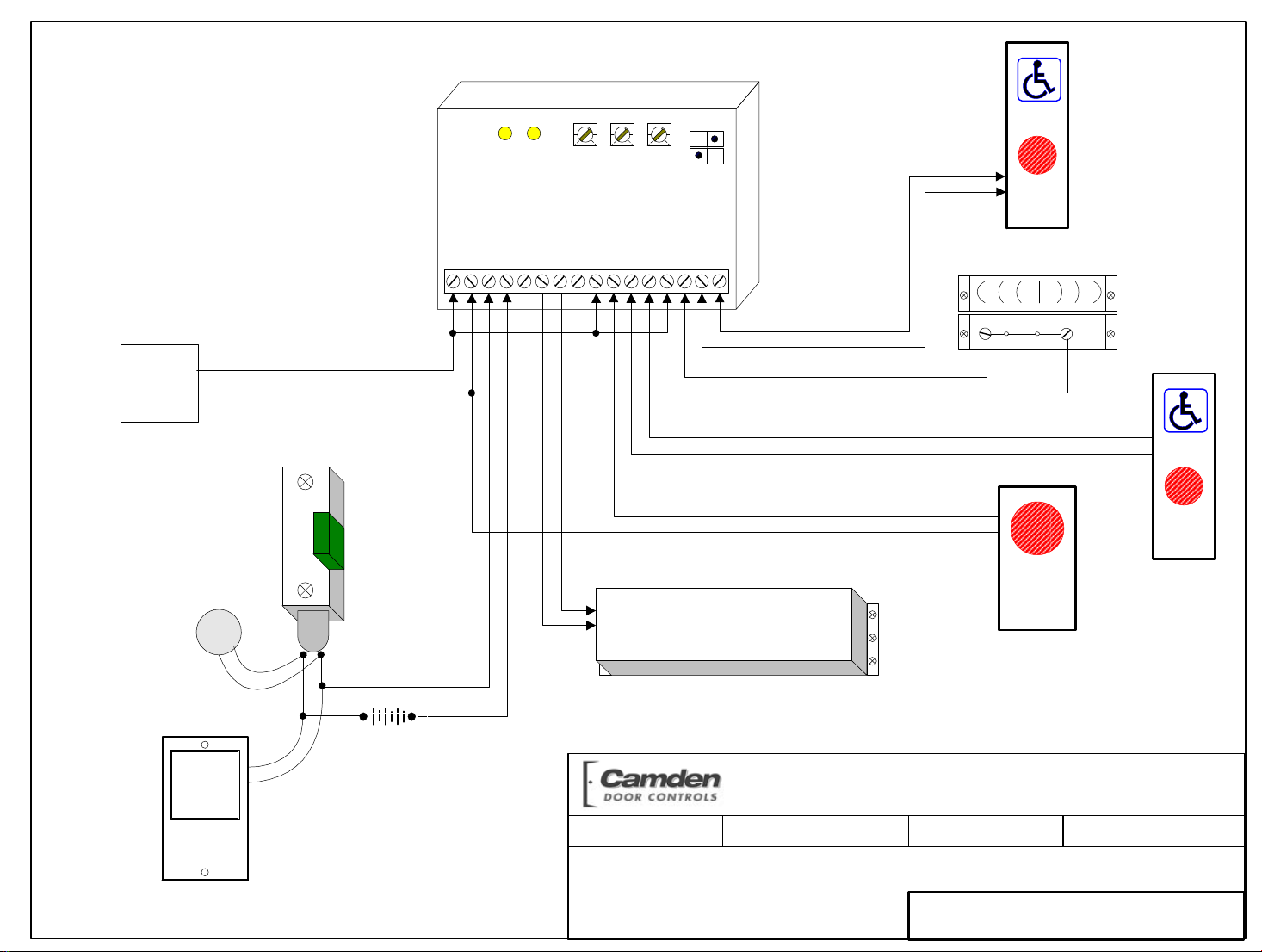
Refer to Diagram #2 for normally unlocked doors, or
Refer to Diagram #3 for normally locked doors.
Connect the inputs from the various switches
according to the appropriate diagram.
Please note that the Magnetic contact switch should
be a Normally Closed switch (contacts closed when
door is closed (at rest), and contacts open when the
door opens).
The “Push to Lock” switch should be a normally-open
momentary switch.
The door lock is connected to Relay 1 (Terminals 3 &
4, or 4 & 5). Both fail safe, and fail secure locks may
be used with the CX-22 controller.
The Automatic Door Operator is typically connected
to Relay 2 (N.O. Terminals 6 & 7).
The unit will operate on 12 or 24 volts, AC or DC.
Connect to Terminals 1 & 2, (they are non-polarity
sensitive).
Page 2 of 8
Off / On
1
2
Off / On
1
2
Off / On
1
2
Off / On
1
2
Page 3

Set up
Apply power to the CX-22 and observe the LED’s.
Pot DOR/RL1 adjusts the Lock release time (up to 30
seconds). The Pot marked DOO/RL2 adjusts the
delay before the Door operator relay fires, and the
Operator hold time is adjusted with Pot DOR/RL2.
Normally Unlocked Mode:
Press the exterior wall switch. If the washroom is
unoccupied the door will open automatically. After
entering the washroom, wait for the door to close,
then push the “Lock” button. The CX-22 will energize
the lock, and remove the outside wall switch from the
circuit.
To exit the washroom, two options are available:
1. To have the door unlock and open
automatically, push the interior wall switch.
This also resets the relay for the next person
to use.
2. Manual use. The door may also be used
manually. To exit the washroom, turn the
lever handle and pull (push) the door open.
The magnet switch resets the relay for the
next person to use.
If a CM-9600 switch is used with this system, you can
connect the LED’s using a CM-9600C harness. Wire
as per Diagram #4.
If using an “OCCUPIED WHEN LIT” sign, such as our
CM-30-OWL, wire as per Diagram #5.
Normally Locked Mode:
In this situation the door is always locked from the
exterior.
Enter code or swipe card. The door unlocks and
after the adjustable delay, opens the door. After
entering the washroom, wait for the door to close,
then push the “Lock” button. You will hear a brief
double click of the strike indicating the door is now
locked, and the outside access control device is
removed from the circuit.
To exit the washroom, two options are available:
3. To have the door unlock and open
automatically, push the interior wall switch.
This also resets the relay for the next person
to use.
4. Manual use. The door may also be used
manually. To exit the washroom, turn the
lever handle and pull (push) the door open.
The magnet switch resets the relay for the
next person to use.
Once the desired operation is achieved, proceed to
Section 4, for System Inspection Instructions.
Section 4 _________________
System Inspection Instructions
After the Installation and operational check of the
system:
1. Place warning label on the door (as per ANSI
A156.10 or A156.19 guidelines). This will
advise the person entering the swing side
zone that the door will move.
2. Instruct the owner on door system operation
and how to test it. This should be checked
on a daily basis.
3. Instruct the owner on what to do if the door or
any of its components become damaged.
4. Strongly recommend to the owner that the
complete entry be inspected twice a year as
part of the service agreement.
Section 5_________________
Technical Data
Model CX-22
Size 3 ¼” x 2 ¼” x ¾”
Mounting Velcro or double-sided tape
Enclosure Protective paper sleeve.
Operating voltage 12 / 24 Volts, AC / DC
Current Draw 18 mA standby,
40 mA max.
Response time 0.3 seconds
Inputs 2 x “dry” contacts,
2 x “wet” contacts:
(3 -30 V AC/DC, Optically
isolated, non-polarity sensitive).
Relay Output 2 x Form C (SPDT)
Relay contact rating 3 amps @ 24 VDC/120 VAC
Time Delays 3 @ 1 to 30 seconds each
Electrical Life 100,000 operations
@ rated capacity
500,000 operations
@ ½ rated capacity
Section 6_________________
Warranty
Camden Door Controls guarantees the CX-22 to be free
from manufacturing defects for 3 years from date of sale.
If during the first 3 years the CX-22 fails to perform
correctly, it may be returned to our factory where it will be
repaired or replaced (at our discretion) without charge.
Except as stated herein, Camden extends no warranties
expressed or implied regarding function, performance or
service.
Questions?
Call us toll-free at 1-877-226-3369
Page 3 of 8
Page 4

12 - 24 V
AC/DC
Power
Off / On
RL1
LED
RL2
LED
DOR
RL1
DOO
RL2
DOR
RL2
1
2
CX-22
1 5234 678910111213141516
Door #2
Push
Switch
Wet
output
ie - RF
receiver
(optional)
Wet
output
ie - RF
receiver
(optional)
Door #1
Operator
Door #1
Push
Switch
SCALE: NONE
DRAWN BY: DGW
CX-22 Bi-Dire ctional Sequen cer Wiring Diagram
DRAWING No: DRG- C X- 2 2- 0 1
Door #2
Operator
Camden Door Controls
DATE: 02/08/09
FILENAME: CX_22 Diagram 1.vsd
5502 Timberlea Blvd
Mississauga, Ontario
L4W 2T7
REVISED:
Page 5

12 - 24 V
AC/DC
Power
Electric Strike
(If Fail-Secure lock
Wire MOV
(supplied)
directly to strike
or magnet
Fail-Safe
Shown
is used, wire to
Terminals 4 & 5)
MOV
Off / On
RL1
LED
RL2
LED
DOR
RL1
DOO
RL2
DOR
RL2
1
2
CX-22
1 5234 678910111213141516
Door #2
Operator
PUSH
TO
LOCK
Inside
Push to Lock
Switch
Outside
Wall Switch
N.C.
Magnetic
Contact
Switch
Inside
Wall Switch
Power
for Strike
SCALE: NONE
DRAWN BY: DGW
CX-22 Normally Un locked Washroom Door Wiring Diagram
DRAWING No: DRG- C X- 2 2- 0 2
Camden Door Controls
DATE: 02/08/09
FILENAME: CX_22 Diagram 2.vsd
5502 Timberlea Blvd
Mississauga, Ontario
L4W 2T7
REVISED: 08/27/12
Page 6

12 - 24 V
AC/DC
Power
Electric Strike
(If Fail-Safe lock is
Wire MOV
(supplied)
directly to strike
or magnet
Fail-Secure
Shown
used, wire to
Terminals 4 & 5)
MOV
Off / On
RL1
LED
RL2
LED
DOR
RL1
DOO
RL2
DOR
RL2
1
2
CX-22
1 5234 678910111213141516
Door #2
Operator
123
456
789
N.C.
PUSH
TO
LOCK
Inside
Push to Lock
Switch
C
Outside
Keypad or
Prox Reader
(Dry Contact)
Magnetic
Contact
Switch
Inside
Wall Switch
Power
for Strike
SCALE: NONE
DRAWN BY: DGW
CX-22 Normally Locked W as hroom Door Wiri ng Diagram
DRAWING No: DRG- C X- 2 2- 0 3
Camden Door Controls
DATE: 02/08/09
FILENAME: CX_22 Diagram 3.vsd
5502 Timberlea Blvd
Mississauga, Ontario
L4W 2T7
REVISED: 08/27/12
Page 7

12 - 24 V
AC/DC
Power
Electric Strike
(If Fail-Secure lock
Terminals 4 & 5)
Wire MOV
(supplied)
directly to strike
or magnet
Fail-Safe
Shown
is used, wire to
MOV
Off / On
RL1
LED
RL2
LED
DOR
RL1
DOO
RL2
DOR
RL2
1
2
CX-22
1 5234 678910111213141516
Door #2
Operator
PUSH
TO
LOCK
CM-9600
Push to Lock
Switch
Outside
Wall Switch
N.C.
Magnetic
Contact
Switch
Inside
Wall Switch
Gray
Red
Gray
Power
for Strike
Harness
plugs
into
CM-9600
circuit
board
SCALE: NONE
DRAWN BY: DGW
CX-22 and Harness for CM -9600 Wiri ng Diag ram
DRAWING No: DRG- C X- 2 2- 0 4
Camden Door Controls
DATE: 08/14/12
FILENAME: CX_22 Diagram 4.vsd
5502 Timberlea Blvd
Mississauga, Ontario
L4W 2T7
REVISED: 08/27/12
Page 8
12 - 24 V
AC/DC
Power
Electric Strike
(If Fail-Secure lock
Terminals 4 & 5)
Wire MOV
(supplied)
directly to strike
or magnet
Fail-Safe
Shown
is used, wire to
MOV
Off / On
RL1
LED
RL2
LED
DOR
RL1
DOO
RL2
DOR
RL2
1
2
CX-22
1 5234 678910111213141516
Door #2
Operator
PUSH
TO
LOCK
Push to Lock
Switch
Outside
Wall Switch
N.C.
Magnetic
Contact
Switch
Inside
Wall Switch
CM-30 OWL
or similar sign
Match voltage
of bulb and
electric strike to
power supply
OCCUPIED
WHEN
LIT
Power
for Strike
SCALE: NONE
DRAWN BY: DGW
CX-22 and CM- 30 OWL “Occupied When Lit” sign
DRAWING No: DRG- C X- 2 2- 0 5
Camden Door Controls
DATE: 08/14/12
FILENAME: CX_22 Diagram 5.vsd
5502 Timberlea Blvd
Mississauga, Ontario
L4W 2T7
REVISED: 08/28/12
 Loading...