

Page 1

LazerpointTM RF TX-9
Transmitter
Installation Instructions
General Description
Camden Lazerpoint™ Radio Controls comprise the following models:
CM-TX-9 Wall switch ready transmitter
CM-RX-91 Basic Receiver
CM-RX-92 Full function (dual relay) Receiver.
TX-9 transmitters utilize readily available AAA batteries, and
special circuitry to assure long life.
A proprietary piezo sounder is used to annunciate low battery,
battery level, and “stuck switch” conditions.
These instructions cover the TX-9 transmitter.
as a small blade screwdriver or similar. Within 10 seconds,
press the switch connected to the TX-9 transmitter. The Green
LED Array will flash once to confirm enrolment. Repeat with
any additional transmitters. Pressing the learned transmitter
again will signal the receiver that you are finished programming
and LED’s 1 & 2 will flash, in an alternating sequence.
Pressing the transmitter a third time will activate the relay and
corresponding LED, and also the device connected to the relay
contacts.
If you wait longer than the 10 second period, the receiver will
time out of Learn Mode and revert back to standby. The LED
will then flash to indicate the number of transmitters learned
into the receiver.
Technical Data
Mounting
Model TX-9 Transmitter
The TX-9 is designed to mount behind a switch in a wall-box, post,
or other suitable enclosure. Double sided tape is used to attach
the circuit board and battery holder securely to the enclosure.
Even though the circuit board is conformal coated, care should
be taken to ensure the transmitter does not get wet.
Frequency: Operates in the 902 – 928 MHz
Codes 1 million (20 bit) codes
Size 2 ¼” L x 5/8” W x 3/8” H
Mounting Double sided foam tape
Switch Connection 2 x 10” leads with ¼” quick
Wiring
Refer to the TX-9 Installation Drawing (see reverse side) for the
following connections:
Connect the transmitter wires to the activating switch (N.O.
momentary dry contacts). Insert 2 fresh AAA alkaline batteries
(provided) into the battery holder (observe proper polarity). Press
the switch and observe the red LED to ensure proper transmission.
Test the transmitter by pressing and holding the switch for 5
seconds. The piezo speaker should sound 5 beeps, meaning the
batteries are at full capacity. This is the Battery Gauge™ feature.
If the piezo beeps only 1 - 3 times, you should change the batteries
for fresh (new) ones.
Now press and hold the switch for 15 seconds. The piezo should
now make a distinctive hi-low sound. This signal will sound for
6 seconds, then turn off for a minute, then sound again.
This is the “stuck switch indicator” feature.
Learning the Transmitter(s) to the Receiver
Built-in Piezo sounder Used for Low Battery status,
Power 2 x AAA alkaline batteries
Battery life Minimum 500,000 operations
Range Over 500 ft (open area)
Temperature rating -40
Warranty
Camden Door Controls guarantees the Lazerpoint™ RF
(TX-9, RX-91,or RX-92 models) to be free from manufacturing
defects for 3 years from date of sale. If during the first 3
years a Lazerpoint RF component fails to perform correctly,
it may be returned to our factory where it will be repaired or
replaced (at our discretion) without charge. Except as stated
herein, Camden extends no warranties expressed or implied
regarding function, performance or service.
ISM Band
disconnect terminations
Battery Gauge™, and Stuck
Switch indicator.
o
to 185o F (-40
o
to +85
o
C)
To learn the transmitter into the receiver, press the PB1
(or PB2) button on the Receiver using a small blunt object such
NOTE: Batteries are exempt from this warranty!
Page 1 of 3
Page 2
FILENAME: TX-9 Installation Drwg.vsd
DRAWING No: TX-9-Installation
TX-9 Typical Installation Examples
SCALE: NONE
DRAWN BY: DGW
REVISED: 16/09/15
DATE: 03/24/10
5502 Timberlea Blvd
Mississauga, Ontario
L4W 2T7
+
-
+
-
+
-
+
-
+
-
+
-
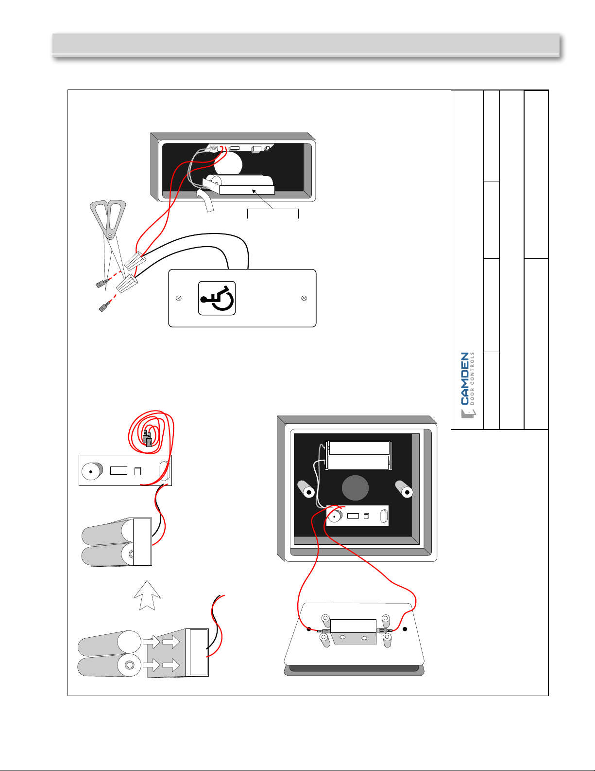
STEP 1
STEP 2a
STEP 2b
OR
Insert two fresh AAA batteries into
battery holder, taking care to match the
positive and negative terminal markings
on case.
USING WITH OUR CM-45 SWITCH & CM-43 BOX
Peel off the release paper on the back of the transmitter
and batter holder.
Position on back of the enclosure ensuring clearance for
the switch (as shown above).
Connect the two red leads to the N.O. and Common
terminals of the switch and mount switch to enclosure
.
Test for proper operation.
USING WITH OUR CM-25 SWITCH & CM-23d BOX
Peel off the release paper on the back of the transmitter and
battery holder.
Position on each side of the enclosure ensuring battery
holder is tight to the bottom of box (as shown above).
Cut off the two ¼" Female connectors, and strip wires.
Connect to the two leads from switch using small twist-on
MARR connectors.
Install switch to box, and test for proper operat
ion.
+
+
AAA
AAA
COM
N.O.
AAA
AAA
PUSH
TO
OPEN
Affix battery
holder to side of
box as close to
bottom as
possible
Camden Door Controls
Lazerpoint™ RF TX-9 Transmitter Installation Instructions
Page 2 of 3
Page 3
Lazerpoint™ RF TX-9 Transmitter Installation Instructions
IC & FCC INFORMATION FOR USERS
IC: 8725A-TX9
This device complies with Industry Canada’s licence-exempt RSSs. Operation is subject to the following two conditions:
(1) This device may not cause interference; and
(2) This device must accept any interference, including interference that may cause undesired operation of the device.
Le présent appareil est conforme aux CNR d’Industrie Canada applicables aux appareils radio exempts de licence. L’exploitation est autorisée aux deux
conditions suivantes :
1) l’appareil ne doit pas produire de brouillage;
2) l’utilisateur de l’appareil doit accepter tout brouillage radioélectrique subi, même si le brouillage est susceptible d’en compromettre le fonctionnement.
FCC ID: 2AHAB-TX9
This device complies with part 15 of the FCC Rules. Operation is subject to the following two conditions: (1) This device may not cause harmful interference,
and (2) this device must accept any interference received, including interference that may cause undesired operation.
This equipment has been tested and found to comply with the limits for a Class B digital device, pursuant to part 15 of the FCC Rules. These limits are
designed to provide reasonable protection against harmful interference in a residential installation. This equipment generates, uses and can radiate radio
frequency energy and, if not installed and used in accordance with the instructions, may cause harmful interference to radio communications. However, there
is no guarantee that interference will not occur in a particular installation. If this equipment does cause harmful interference to radio or television reception,
which can be determined by turning the equipment off and on, the user is encouraged to try to correct the interference by one or more of the following
measures:
—Reorient or relocate the receiving antenna.
—Increase the separation between the equipment and receiver.
—Connect the equipment into an outlet on a circuit different from that to which the receiver is connected.
—Consult the dealer or an experienced radio/TV technician for help.
Changes or modications made to this equipment not expressly approved by Camden Door Control could void the user’s authority to operate the equipment.
OEM Labeling Requirements
WARNING: The Original Equipment Manufacturer (OEM) must ensure that FCC labeling requirements are met. This includes a clearly visible label on the
outside of the nal product enclosure that displays the contents shown in the gure below.
Required FCC Label for OEM products containing the CM-TX-9 Module.
Contains FCC ID: 2AHAB-TX9 & IC: 8725A-TX9
This device complies with Part 15 of the FCC Rules. Operation is subject to the following two conditions: (1) this device may not cause harmful interference
and (2) this device must accept any interference received, including interferences that may cause undesired operation.
IMPORTANT: OEMs must test nal product to comply with unintentional radiators (FCC section 15.107 & 15.109) before declaring compliance of their nal
product to Part 15 of the FCC Rules.
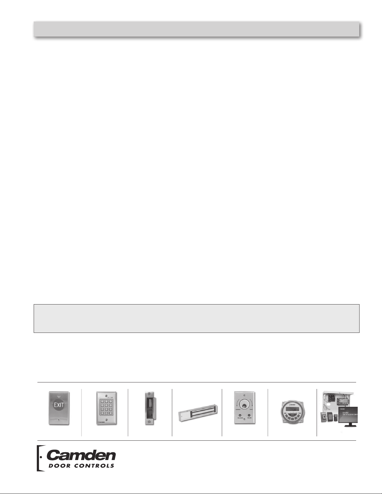
Push Buttons Key Pads Strikes Magnetic Locks Key Switches Relays & Timers Access Control
5502 Timberlea Blvd.,
Mississauga, ON Canada
L4W 2T7
www.camdencontrols.com
Toll Free: 1.877.226.3369
File: Lazerpoint RF TX-9
Manual .indd Rev.6
Revised: 19/05/2016
Part No.: 40-82B120
Page 3 of 3
 Loading...