

Page 1

Newton Series®HD P300HD
High Definition Powered Subwoofer User Manual
Page 2
WARNING
The lightning flash with arrowhead, within an equilateral triangle, is intended to
alert the user to the presence of uninsulated “danger
product’s enclosure that may be of sufficient magnitude to constitute risk of
electric shock to persons.
ous voltage” within the
WARNING
DO NOT OPEN
TO PREVENT THE RISK OF ELECTRIC
SHOCK, DO NOT REMOVE
SUBWOOFER’S COVER. NO USER-
SERVICEABLE PARTS INSIDE.
REFER SERVICING TO QUALIFIED
SERVICE PERSONNEL.
The exclamation point within an equilateral triangle is intended to aler
to the presence of important operating
and maintenance (servicing) instructions
in the literature accompanying this
product
AVISIQUE
POUR EVITER TOUT RISQUE DE
CHOC ELECTRIQUE, NE PAS
DEMONTER LE COUVERCLE DU
HAUT PARLEUR. AUCUN ENTRETIEN DES PIECES INTERIEURES
N’EST REQUIS.TOUT SERVICE
D’ENTRETIEN NE DOIT ETRE
EFFECTUE QUE PAR DU PERSON-
NEL D’ENTRETIEN QUALIFIE.
t the user
READ AND HEED IMPORTANT SAFETY WARNING
ON BACK OF SUBWOOFER ENCLOSURE
CAUTION:
TO PREVENT ELECTRIC SHOCK, MATCH WIDE
BLADE OF PLUG TO WIDE SLOT, INSERT FULLY.
ATTENTION:
POUR EVITER LES CHOCS ELECTRIQUES, INTRO
DUIRE LA LAME LA PLUS LARGE DE LA FICHE
DANS LA BORNE CORRESPONDANTE DE LA PRISE
ET POUSSER JUSQU’AU FOND.
-
IMPORTANT NOTICE:
THE SERIAL NUMBER FOR THE SUBWOOFER IS
LOCATED ON THE SUBWOOFER’S CONTROL PANEL.
PLEASE WRITE THIS NUMBER DOWN AND KEEP IT
IN A SECURE AREA. THIS IS FOR YOUR SECURITY
2
.
Page 3

IMPORTANT SAFETY INSTRUCTIONS
READ INSTRUCTIONS – All safety and operating instruc-
tions should be read before the subwoofer is operated.
RETAIN INSTRUCTIONS – The safety and operating
instructions should be retained for future reference.
HEED WARNINGS – All warnings on the subwoofer and in
the operating instructions should be adhered to.
FOLLOW INSTRUCTIONS – All operating and use instructions should be followed.
CLEANING – Unplug the subwoofer or control module from
the wall outlet or other power source before cleaning. Use
a damp cloth for cleaning.
ATTACHMENTS – Do not use any adapters or attachments
not recommended by Cambridge SoundWorks as they may
cause hazards.
ATER AND MOISTURE
W
control module near water-for example, near a bath tub,
wash bowl, kitchen sink, or laundry tub; in a wet basement;
or near a swimming pool or other similar areas.
ACCESSORIES – Do not place the subwoofer on an unstable cart, stand, tripod, bracket, or table. The subwoofer
may fall, causing serious injury to a child or adult and serious damage to the product.
VENTILATION – Slots, openings and metal fins in the cabinet are provided for ventilation, to ensure reliable operation
of the subwoofer and to prevent it from overheating. These
areas must not be blocked or covered such as by placing
the product on a bed, sofa, very deep pile rug, or other
similar surface. The subwoofer should not be placed in a
built-in installation such as a bookcase or rack.
HEAT – The subwoofer should be situated away from heat
sources such as radiators, heat registers, stoves, and other
products (including amplifiers) that produce heat.
POWER SOURCES – The subwoofer or contr
should be operated only from the type of power source
indicated on the label. If you ar
power supply to your home, consult your dealer or local
power company.
POLARIZATION – The subwoofer is equipped with a polarized alter
wider than the other). This plug will fit into the power outlet
only one way. This is a safety feature. If you are unable to
insert the plug fully into the outlet, try reversing the plug. If
the plug should still fail to fit, contact your electrician to
eplace your obsolete outlet. Do not defeat the safety pur-
r
pose of the polarized plug.
POWER-CORD PROTECTION – The AC power cords
should be routed so that they are not likely to be walked
on. No object should bring weight to bear on to the AC
power cords.
nating-curr
– Do not use the subwoofer or
ol module
e not sur
ent line plug (a plug having one blade
e of the type of
LIGHTNING – For added protection for the subwoofer or
control module during a lightning storm, or when it is left
unattended and unused for long periods of time, unplug
om the wall outlet. This will prevent damage to the
them fr
subwoofer or control module due to lightning and powerline surges.
OVERLOADING – Do not overload wall outlets, extension
cords, or integral convenience receptacles as this can
esult in a risk of fire or electric shock.
r
OBJECT AND LIQUID ENTRY – Never use probes of any
kind to reach into the subwoofer or control module as they
may touch dangerous voltage points or short parts that
could result in a fire or electric shock. Never spill liquid of
any kind on the subwoofer, control module or control module power supply.
SERVICING – Do not attempt to service the subwoofer or
control module yourself as opening or removing covers
may expose you to dangerous voltage or other hazards.
Refer all servicing to qualified service personnel.
DAMAGE REQUIRING SERVICE – Unplug the subwoofer
or control module from the wall outlet or other power
source and refer servicing to qualified service personnel
under the following conditions:
a) When the power-cord or plug is damaged.
b) If liquid has been spilled, or objects have fallen into the
subwoofer or control module.
c) If the subwoofer or control module has been exposed to
rain or water.
d) If the subwoofer or control module does not operate
normally by following the operating instructions; or
exhibits a distinct change in performance.
e) If the subwoofer or contr
damaged in any way.
REPLACEMENT PARTS – When replacement parts are
required, be sure the service technician uses replacement
ts specified by Cambridge SoundW
par
same characteristics as the original part. Substandard
substitutions may result in fire, electric shock, or other hazards.
SAFETY
repairs to the subwoofer or control module, ask the service
technician to perform safety checks to determine that the
subwoofer or contr
tion.
CHECK
- Upon completion of any service or
ol module is in proper operating condi-
ol module has been dr
orks or have the
opped or
3
Page 4
INTRODUCTION
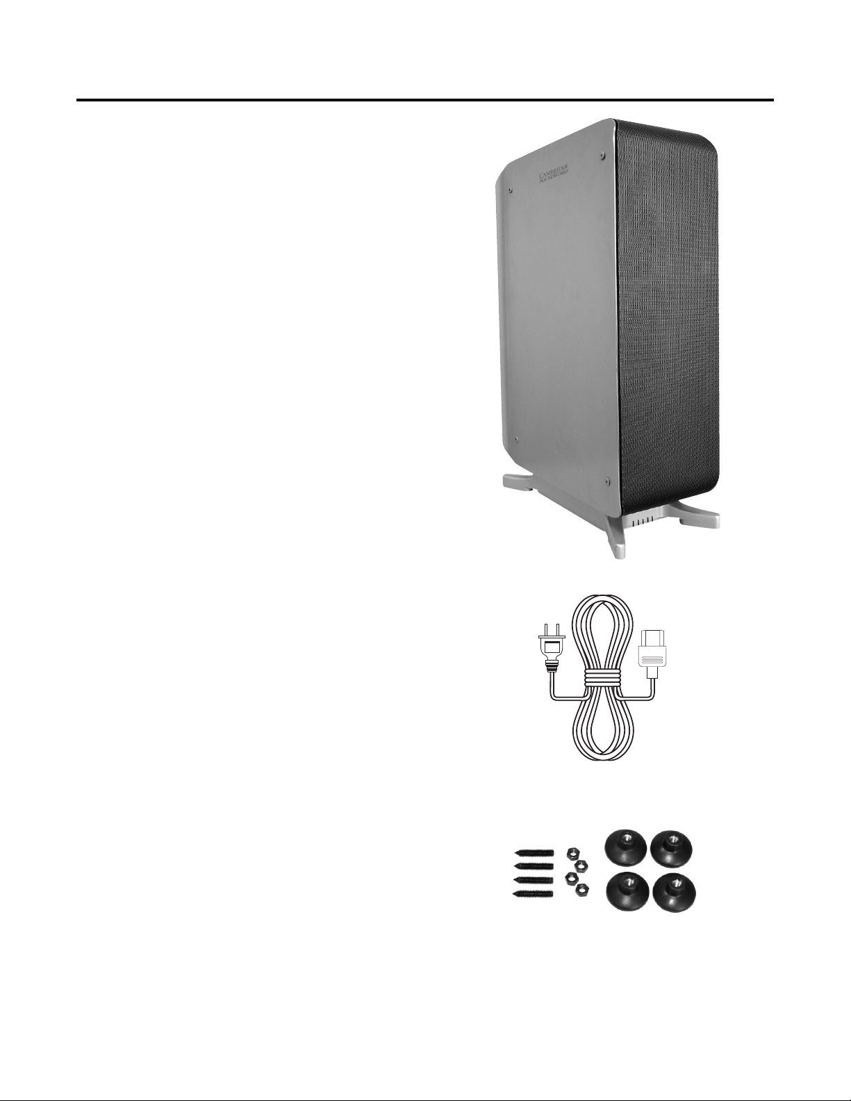
Thanks for choosing a Newton HD Series speaker. The
P300 HD features the finest drivers, precision internal
crossover circuitry, and an elegant enclosure design.
The design team at Cambridge SoundW
is no better combination of audiophile-level attention to
detail and reasonable cost.
AFTER UNPACKING
Save the shipping carton and packing material for future use
and transport.
CONTENTS
1. One Subwoofer
2. One power cord
3. Four screw-on feet with nuts and threaded studs
4. Owner’s manual
INSPECTING FOR DAMAGE
Examine each part carefully for shipping damage. If there is
any, do not install or use the speaker. Return the speaker to
the merchant where you made the purchase or call
Cambridge SoundWorks at 1-800 FOR-HIFI (1-800-367-
4434) for assistance.
orks believes there
1.
2.
3.
4
Page 5

SYSTEM CONFIGURATION
The P300 HD may be used with virtually any system.
Typically, you will use the SUBWOOFER or LFE output from
your receiver or processor to supply signal to the P300. You
may also use the speaker outputs from a receiver or amplifier that does not have a separate SUBWOOFER output.
One P300 is sufficient for most rooms. For higher output or
very large rooms, a second P300 may be used.
ATTACH THE FEET
The P300 HD is supplied with screw-on feet to assure a stable, level mounting. Locate the four threaded spikes, four
locknuts, and four round feet. First, screw the four spikes
fully into the threaded holes in the legs of the amplifier housing. Orient the spikes so that the pointed end points into the
threaded hole. Next, screw a locknut onto each spike until it
just contacts the bottom of the amplifier housing. Do not
tighten it. Then, screw a foot onto each of the spikes. Once
the subwoofer is in its final position, adjust each foot so that
the unit is level and stable. Tighten each locknut against the
top of its corresponding foot to hold everything in place.
On some thickly carpeted floors, the compliance of the carpet padding may make the subwoofer unstable when using
the feet. If this happens, remove the feet and invert the
pointed end of the spikes so that they point downwards,
through the carpet. The tips of the spikes should pierce the
carpet and support the subwoofer firmly on the floor below.
Adjust each spike to level the subwoofer and tighten each
locknut against the bottom of the aluminum amplifier housing. Be extremely careful handling or moving the speaker
with the spikes exposed. Be advised that if you choose this
method the spikes will damage the finish of the sub-floor.
5
Page 6

PLACEMENT
The output of the subwoofer is strongly affected by room
boundaries such as the floor and walls. The evenness of the
response throughout the room is also affected by the placement. Because each room has its own unique acoustic
character, experimentation with placement is essential to get
the best overall performance.
Each floor or wall boundary will increase the output in the
listening area. Placing the subwoofer close to the corner of
the room will result in the strongest output, and works best
in most rooms. Placing it against the wall, away from the
corner will produce slightly less output. Placing it away from
all boundaries will produce the least.
Reflections from the various surfaces that form the room
can also result in some areas of strong bass, and others
with very weak bass due to the way the reflections interact
with the primary output. Try placing the subwoofer in a variety of locations while listening from multiple seating positions. Leave the subwoofer where the response is strong
and even from all seating positions.
Maxium Bass Output
Moderate Bass Output
Least Bass Output
6
Page 7

WIRING
COAX
DIGITAL INPUTS
OPTICAL
MAIN RIGHT
TO FRONT LEFT &
RIGHT SPEAKERS
TO SUB'S
SPEAKER LEVEL
INPUTS
MAIN LEFT
CENTER
REAR RIGHT
REAR RIGHT
SPEAKER OUTPUTS
Red Band
White Band
COAX
SUB OUT
DIGITAL
INPUTS
MAIN RIGHT
MAIN LEFT
CENTER
REAR RIGHT
REAR RIGHT
SPEAKER OUTPUTS
SIGNAL CABL
E
WITH RCA PLUGS
RECEIVER
OPTICAL
The wiring you need depends on the signal source you are
using. The most common source is a surround processor
with a dedicated SUBWOOFER or LFE output. Use a highquality shielded cable with a Phono plug on each end from
the surround processor’s output to either the L or R input
jack of the P300 HD.
It is also possible to connect the P300 HD to a stereo
receiver or preamplifier with Left and Right full range outputs. Connect a pair of shielded cables equipped with
Phono plugs on each end to the L & R preamplifier outputs
of your source unit to the L & R input jacks of the P300 HD.
Finally, you may use a stereo receiver or amplifier equipped
with only speaker outputs. Connect conventional
18 speaker wire to the small speaker plug supplied with the
P300 HD. Connect the other end of these wires to the same
set of speaker terminals used for your main left and right
speakers.
Connect the power cord (supplied) to the AC power input on
the rear of the subwoofer. Connect the other end to a
110–120V, 50-60Hz AC outlet. After all connections are
made, turn on the main AC power switch. For normal use,
this power switch may remain on. An automatic circuit will
turn the subwoofer ON automatically in the presence of a
signal, and STANDBY approximately 20 minutes after the
signal has stopped.
AWG#14 –
This jack is usually labeled "SUB OUT," but it may
say "SUBWOOFER" or "LFE OUTPUT". Check
the receiver owner's manual to identify it.
Dolby Digital and Dolby Surround receiver
Line level connector
ALTERNATE CONNECTION
The RJ1
Cambridge SoundW
control consoles.
1 input jack provides compatibility with the
orks Newton Series P500 and P1000
ou may connect a P300 HD to a system
Y
containing the control console either as a replacement for,
or in addition to the original P500 or P1000 subwoofer
enclosure. Set the P300 HD crossover and volume controls
fully counterclockwise and the phase switch to the 0-degree
position. Use the adjustments on the control console as you
would with the original P500 or P1000 to set-up your system.
Connect plug to speaker output
7
Page 8

ADJUSTMENTS
ith a surround processor:
W
When using the subwoofer output of a surround processor,
set the P300 HD’s frequency control fully clockwise. Try the
Phase switch in both positions and leave it in the position
that yields the most bass. If there is no audible dif
between the two positions in your room, leave the switch in
the 0-degree (out) position.
our surround processor has a variety of adjustments to
Y
optimize the sound based on the speakers’ capabilities and
placement. These adjustments vary by processor, so refer to
your processor’s manual for instructions specific to your
equipment. Set your main, center, and surround settings to
“SMALL”, with subwoofer “ON”. Set the volume control on
top of the P300 HD to its centered position and use the
processor’s level adjustments to balance the system. You
may then use the control on the P300 HD to quickly finetune the subwoofer level for different program material.
ference
With no surround processor:
When using a source component that does not have a dedicated subwoofer output you must use the crossover frequency adjustment of the P300 HD to match the low frequency capability of your main speakers. Determine the final
settings by ear. Refer to the specifications of your main
speakers to determine the best setting to use as a starting
point for this control. You should start from the low frequency limit of your main speakers. For most small satellite
speakers typical of home theater systems, this will be
between 65 – 100Hz. If you are using the MC600 HD as
your main speakers, set the crossover to 80Hz. Room characteristics are very strong in this frequency range, so don’t
be surprised if the final settings you like are far from the
starting point.
leave it in the position that yields the most bass. If there is
no audible dif
room, leave the switch in the 0-degree (out) position. Use
the volume control on top of the P300HD balance the sys
tem. Listen to a variety of program material with good bass
to fine-tune the various settings. In a properly set up system
the bass should be smooth and clear, but from the listening
position it should sound as if it is coming from the main
speakers, not from a separate subwoofer. If is is not the
case, your subwoofer may be too loud, or the crossover frequency may be set too high.
Try the Phase switch in both positions and
ference between the two positions in your
-
8
Page 9

SPECIFICATIONS
Enclosure Cleaning
The speaker enclosures can be cleaned with a soft cloth.
Brush or vacuum the grille panels with a soft brush attachment to your vacuum cleaner.
Specifications
Dimensions: 27” H x 17-1/2" W x 8-1/8" D
Weight: 70 pounds
Amplifier power: 300W RMS Class-D with high efficiency
switch-mode power supply.
Frequency Range: 25 – 200Hz. depending on crossover
setting.
oofer Type: 6 x 5-1/4” with bi-laminate composite cones
W
and butyl-rubber surrounds.
Passive Radiator: 6 x 6.5” inverted dome
Crossover: 4th order Linkwitz-Riley adjustable-frequency
low-pass.
Enclosure: MDF with powder-coated steel side panels.
9
Page 10

WARRANTY
10
Page 11

11
Page 12

P81-2310
 Loading...